Embed Size (px)
Citation preview

Printed Circuit Board
49
Contents
Printed Circuit BoardOverview
50
PCB Connector Options 50
DRC Series 51-52
DT Family 53-55
HD10 Series 55
STRIKE Series 55
PCB Enclosures and Headers 56-57
Electronic Module DesignRecommendations
58-59
A STEP AHEAD
50
Printed Circuit Board Connectors
Printed Circuit Board Overview
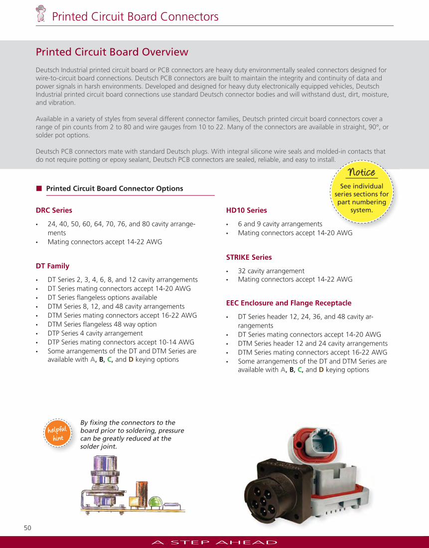
Deutsch Industrial printed circuit board or PCB connectors are heavy duty environmentally sealed connectors designed for wire-to-circuit board connections. Deutsch PCB connectors are built to maintain the integrity and continuity of data and power signals in harsh environments. Developed and designed for heavy duty electronically equipped vehicles, Deutsch Industrial printed circuit board connections use standard Deutsch connector bodies and will withstand dust, dirt, moisture, and vibration.
Available in a variety of styles from several different connector families, Deutsch printed circuit board connectors cover a range of pin counts from 2 to 80 and wire gauges from 10 to 22. Many of the connectors are available in straight, 90°, or solder pot options.
Deutsch PCB connectors mate with standard Deutsch plugs. With integral silicone wire seals and molded-in contacts that do not require potting or epoxy sealant, Deutsch PCB connectors are sealed, reliable, and easy to install.
DRC Series
• 24, 40, 50, 60, 64, 70, 76, and 80 cavity arrange-ments
• Mating connectors accept 14-22 AWG
DT Family
• DT Series 2, 3, 4, 6, 8, and 12 cavity arrangements• DT Series mating connectors accept 14-20 AWG • DT Series fl angeless options available• DTM Series 8, 12, and 48 cavity arrangements• DTM Series mating connectors accept 16-22 AWG• DTM Series fl angeless 48 way option• DTP Series 4 cavity arrangement• DTP Series mating connectors accept 10-14 AWG• Some arrangements of the DT and DTM Series are
available with A, B, C, and D keying options
HD10 Series
• 6 and 9 cavity arrangements• Mating connectors accept 14-20 AWG
STRIKE Series
• 32 cavity arrangement• Mating connectors accept 14-22 AWG
EEC Enclosure and Flange Receptacle
• DT Series header 12, 24, 36, and 48 cavity ar-rangements
• DT Series mating connectors accept 14-20 AWG• DTM Series header 12 and 24 cavity arrangements• DTM Series mating connectors accept 16-22 AWG• Some arrangements of the DT and DTM Series are
available with A, B, C, and D keying options
Printed Circuit Board Connector Options
By fi xing the connectors to the board prior to soldering, pressure can be greatly reduced at the solder joint.
helpfulhelpfulhinthint
Jiffy Splicesaccept one pin and one
socket.
Noteall.
Jiffy Splicesaccept onepin and one
socket.
NoteN tNote
See individualseries sections for part numbering
system.
NoticeNotice
A STEP AHEAD
51
Printed Circuit Board Connectors
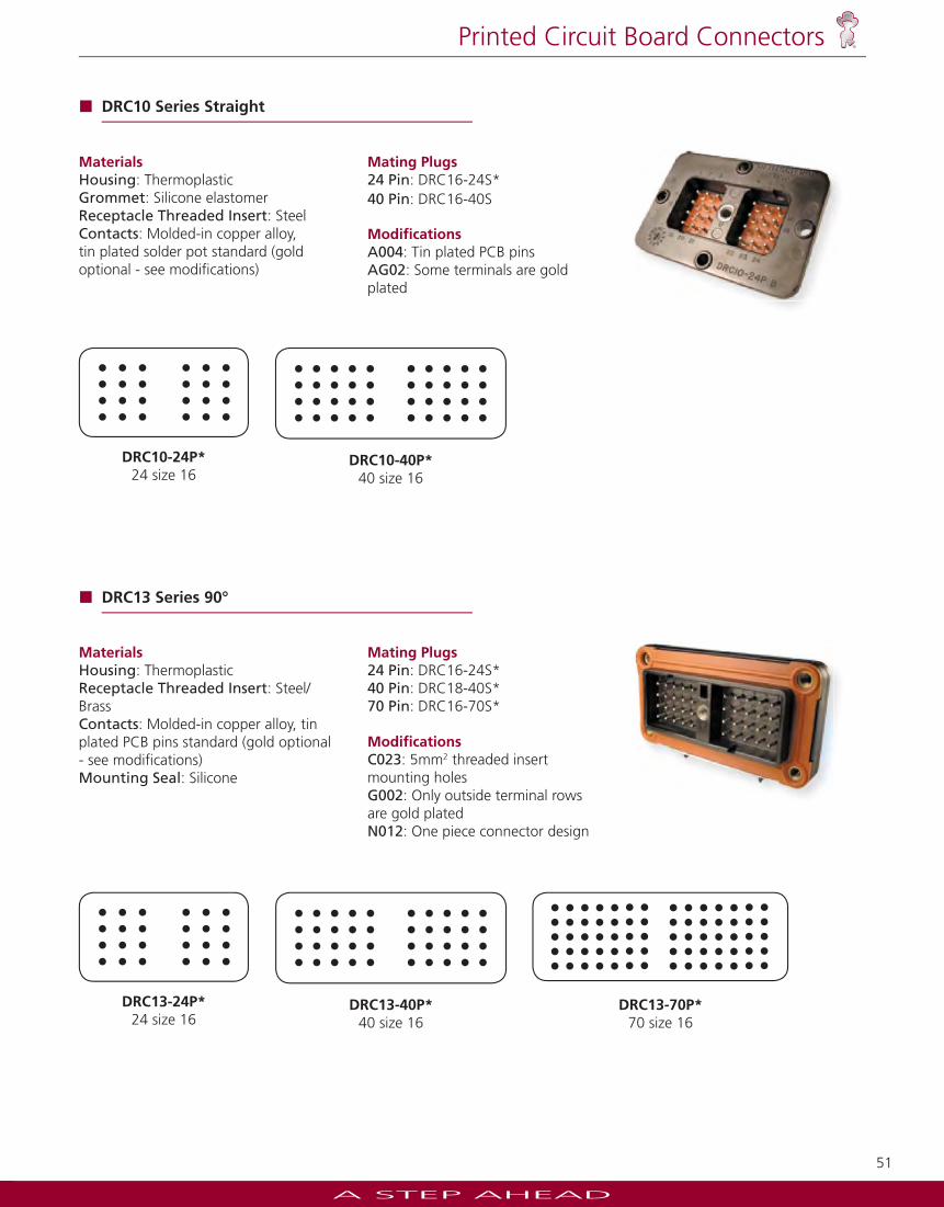
MaterialsHousing: ThermoplasticGrommet: Silicone elastomerReceptacle Threaded Insert: SteelContacts: Molded-in copper alloy, tin plated solder pot standard (gold optional - see modifi cations)
Mating Plugs24 Pin: DRC16-24S*40 Pin: DRC16-40S
Modifi cations A004: Tin plated PCB pins AG02: Some terminals are gold plated
MaterialsHousing: ThermoplasticReceptacle Threaded Insert: Steel/BrassContacts: Molded-in copper alloy, tin plated PCB pins standard (gold optional - see modifi cations)Mounting Seal: Silicone
Mating Plugs24 Pin: DRC16-24S*40 Pin: DRC18-40S*70 Pin: DRC16-70S*
Modifi cations C023: 5mm2 threaded insert mounting holesG002: Only outside terminal rows are gold plated N012: One piece connector design
DRC10 Series Straight
DRC10-40P*40 size 16
DRC10-24P*24 size 16
DRC13 Series 90°
DRC13-40P*40 size 16
DRC13-24P*24 size 16
DRC13-70P*70 size 16
A STEP AHEAD
52
Printed Circuit Board Connectors
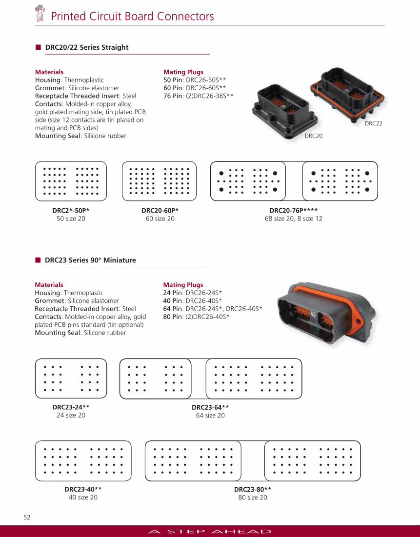
DRC23 Series 90° Miniature
DRC23-40**40 size 20
DRC23-24**24 size 20
DRC23-64**64 size 20
DRC23-80**80 size 20
MaterialsHousing: ThermoplasticGrommet: Silicone elastomerReceptacle Threaded Insert: SteelContacts: Molded-in copper alloy, gold plated PCB pins standard (tin optional) Mounting Seal: Silicone rubber
Mating Plugs24 Pin: DRC26-24S*40 Pin: DRC26-40S*64 Pin: DRC26-24S*, DRC26-40S*80 Pin: (2)DRC26-40S*
MaterialsHousing: ThermoplasticGrommet: Silicone elastomerReceptacle Threaded Insert: SteelContacts: Molded-in copper alloy, gold plated mating side, tin plated PCB side (size 12 contacts are tin plated on mating and PCB sides)Mounting Seal: Silicone rubber
Mating Plugs50 Pin: DRC26-50S**60 Pin: DRC26-60S**76 Pin: (2)DRC26-38S**
DRC20/22 Series Straight
DRC20-76P****68 size 20, 8 size 12
DRC20-60P*60 size 20
DRC2*-50P*50 size 20
DRC20
DRC22

A STEP AHEAD
53
Printed Circuit Board Connectors
DT13/15 Series 90° or Straight
DT1*-6P6 size 16
DT1*-2P2 size 16
DT1*-4P4 size 16
DT1*-08P*8 size 16A, B, C, D
DT1*-12P*12 size 16A, B, C, D
DTM13/15 Series 90° or Straight
DTM1*-12P*12 size 20A, B, C, D
DTP10 Series Straight
DTP10-4P4 size 12
MaterialsHousing: ThermoplasticContacts: Molded-in copper alloy, tin plated (gold optional - consult factory)Mounting Seal: Silicone rubber
Mating Plugs2 Pin: DT06-2S4 Pin: DT06-4S6 Pin: DT06-6S8 Pin: DT06-8S*12 Pin: DT06-12S*
Modifi cations B016: Extended shell and additional keys G003: Gold plated pins
MaterialsHousing: ThermoplasticContacts: Molded-in copper alloy, tin plated (gold optional - consult factory)Mounting Seal: Silicone rubber
Mating Plugs12 Pin: DTM06-12S*
MaterialsHousing: ThermoplasticContacts: Molded-in copper alloy, tin platedMounting Seal: Silicone rubber
Mating Plugs4 Pin: DTP06-4S
DT13
DTM13
DTM15
DT15
Jiffy Splicesaccept one pin and one
socket.
NoteJiffy Splicesaccept one pin and one
socket.
NoteNote
Camcar thread forming screws
are recommended. See drawing.
NoticeNotice
A STEP AHEAD
54
Printed Circuit Board Connectors
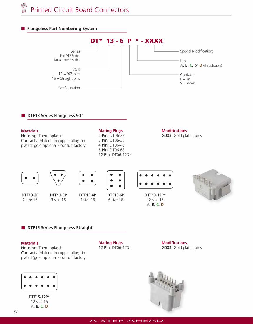
DT* 13 - 6 P * - XXXX
SeriesF = DTF Series
MF = DTMF Series
Style 13 = 90° pins
15 = Straight pins
Confi guration
Special Modifi cations
KeyA, B, C, or D (if applicable)
ContactsP = Pin S = Socket
Flangeless Part Numbering System
DTF13 Series Flangeless 90°
DTF13-12P* 12 size 16A, B, C, D
DTF13-6P6 size 16
DTF13-2P 2 size 16
DTF13-3P 3 size 16
DTF13-4P 4 size 16
MaterialsHousing: ThermoplasticContacts: Molded-in copper alloy, tin plated (gold optional - consult factory)
Mating Plugs2 Pin: DT06-2S3 Pin: DT06-3S 4 Pin: DT06-4S6 Pin: DT06-6S12 Pin: DT06-12S*
Modifi cationsG003: Gold plated pins
DTF15 Series Flangeless Straight
DTF15-12P* 12 size 16A, B, C, D
MaterialsHousing: ThermoplasticContacts: Molded-in copper alloy, tin plated (gold optional - consult factory)
Mating Plugs12 Pin: DT06-12S*
Modifi cations G003: Gold plated pins

A STEP AHEAD
55
Printed Circuit Board Connectors
HD10 Series Straight
FB
AC E
D
HD10-6-96P-N0056 size 16
A
DE
B
JH G
CF
HD10-9-96P-N0059 size 16
MaterialsHousing: ThermoplasticContacts: Molded-in copper alloy, nickel plated Mounting Seal: Standard O-rings may be used
Mating Plugs6 Pin: HD16-6-96S9 Pin: HD16-9-96S
Modifi cations N005: Straight reduced diameter pins supplied as standard
DTMF15 Series Miniature Straight
DTMF15-48P(4)12 size 20
MaterialsHousing: ThermoplasticContacts: Molded-in copper alloy, tin plated (gold optional - consult factory)
Mating Plugs12 Pin: (4) DTM06-12S*
Modifi cations B026: Alternate keying position
MaterialsHousing: ThermoplasticContacts: Molded-in copper alloy, tin plated (gold optional - consult factory)Mounting Seal: Silicone rubber
Mating Plugs32 Pin: SRK06-MD*-32A-***
SRK1*-MD*-32A-001-****4 - Size 16
28 - Size 20
STRIKE13/15 Series 90° or Straight
A STEP AHEAD
56
Printed Circuit Board Connectors
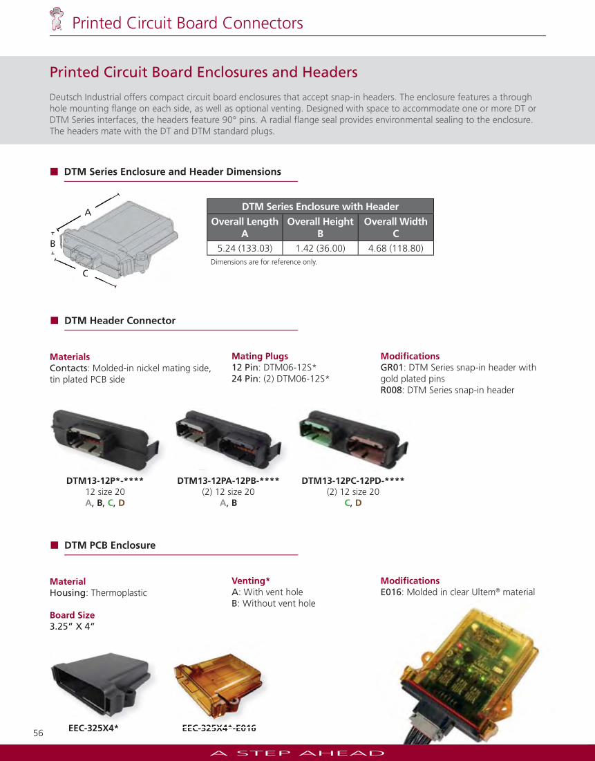
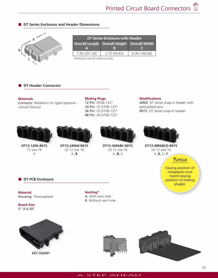
Printed Circuit Board Enclosures and Headers
Deutsch Industrial offers compact circuit board enclosures that accept snap-in headers. The enclosure features a through hole mounting fl ange on each side, as well as optional venting. Designed with space to accommodate one or more DT or DTM Series interfaces, the headers feature 90° pins. A radial fl ange seal provides environmental sealing to the enclosure. The headers mate with the DT and DTM standard plugs.
DTM Series Enclosure with HeaderOverall Length
AOverall Height
BOverall Width
C5.24 (133.03) 1.42 (36.00) 4.68 (118.80)
Dimensions are for reference only.
DTM Series Enclosure and Header Dimensions
A
B
C
A
C
DTM PCB Enclosure
MaterialHousing: Thermoplastic
Board Size3.25” X 4”
Venting*A: With vent holeB: Without vent hole
Modifi cations E016: Molded in clear Ultem® material
EEC-325X4* EEC-325X4*-E016EEC 325X4* E016EEC 325X4*
DTM Header Connector
MaterialsContacts: Molded-in nickel mating side, tin plated PCB side
Mating Plugs12 Pin: DTM06-12S*24 Pin: (2) DTM06-12S*
Modifi cations GR01: DTM Series snap-in header with gold plated pins R008: DTM Series snap-in header
DTM13-12P*-****12 size 20A, B, C, D
DTM13-12PA-12PB-****(2) 12 size 20
A, B
DTM13-12PC-12PD-****(2) 12 size 20
C, D
A STEP AHEAD
57
Printed Circuit Board Connectors
DT PCB Enclosure
MaterialHousing: Thermoplastic
Board Size5” X 6.50”
Venting*A: With vent holeB: Without vent hole
EEC-5X650*EEC 5X650*
DT Header Connector
MaterialsContacts: Molded-in tin (gold optional - consult factory)
Mating Plugs12 Pin: DT06-12S*24 Pin: (2) DT06-12S*36 Pin: (3) DT06-12S*48 Pin: (4) DT06-12S*
Modifi cations GR02: DT Series snap-in header with gold plated pinsR015: DT Series snap-in header
DT13-12PA-R01512 size 16
A
DT13-24PAB-R015(2) 12 size 16
A, B
DT13-36PABC-R015(3) 12 size 16
A, B, C
DT13-48PABCD-R015(4) 12 size 16
A, B, C, D
DT13-48PABCD-R015DT13 12PA R015 DT13-24PAB-R015 DT13-36PABC-R015
DT Series Enclosure with HeaderOverall Length
AOverall Height
BOverall Width
C7.93 (201.30) 2.15 (54.63) 6.30 (160.00)
Dimensions are for reference only.
DT Series Enclosure and Header Dimensions
B
A
C
A
C
Jiffy Splicesaccept one pin and one
socket.
NoteB, C, D
Jiffy Splicesaccept one pin and one
socket.
NoteNote
Keying position of receptacle must match keying
position of mating plug(s).
NoticeNotice
A STEP AHEAD
58
Printed Circuit Board Connectors
Electronic Module Design Recommendations
Deutsch connectors are designed to handle all environmental conditions typically seen on heavy duty equipment. Design considerations have been given for temperature, vibration, and high current levels to exist simultaneously in a connector with no performance degradation.
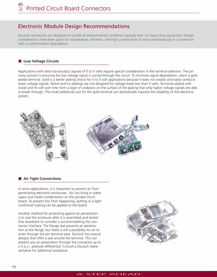
Applications with data input/output signals of 0 to 5 volts require special consideration in the terminal selection. The pri-mary concern is ensuring the low voltage signal is carried through the circuit. To minimize signal degradation, select a gold plated terminal. Gold is a better plating choice for 0 to 5 volt applications because it does not oxidize and easily conducts lower voltage signals. Nickel and tin platings are not designed for voltage levels less than 5 volts. Terminals plated with nickel and tin will over time form a layer of oxidation on the surface of the plating that only higher voltage signals are able to break through. The small additional cost for the gold terminal can dramatically improve the reliability of the electronic system.
Low Voltage Circuits
Air Tight Connections
In some applications, it is important to prevent air from penetrating electronic enclosures. Air can bring in water vapor and create condensation on the printed circuit board. To prevent this from happening, potting or a light conformal coating can be applied to the board.
Another method for protecting against air penetration is to seal the enclosure after it is assembled and tested. One drawback to consider is accommodating the con-nector interface. The fl ange seal prevents air penetra-tion at the fl ange, but there is still a possibility for air to enter through the pin terminal area. Deutsch has several designs that offer a seal around the terminal. This can prevent any air penetration through the connector up to a 5 p.s.i. pressure differential. Consult a Deutsch repre-sentative for additional assistance.
A STEP AHEAD
59
Printed Circuit Board Connectors
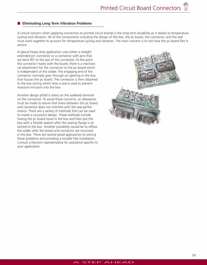
Eliminating Long Term Vibration Problems
A typical heavy duty application uses either a straight extended pin connector or a connector with pins that are bent 90° to the axis of the connector. At the point the connector mates with the board, there is a mechani-cal attachment for the connector to the pc board which is independent of the solder. The engaging end of the connector normally goes through an opening in the box that houses the pc board. The connector is then attached to the box during which time a seal is used to prevent moisture intrusion into the box.
Another design pitfall is stress on the soldered terminal on the connector. To avoid these concerns, an allowance must be made to assure that stress between the pc board and connector does not interfere with the seal perfor-mance. There are a variety of methods that can be used to create a successful design. These methods include having the pc board loose in the box and then pot the box with a fl exible sealant after the sealing fl ange is at-tached to the box. Another possibility would be to refl ow the solder after the board and connector are mounted in the box. There are several good approaches to solving these problems and providing a trouble free installation. Consult a Deutsch representative for assistance specifi c to your application.
A critical concern when applying connectors to printed circuit boards is the long term durability as it relates to temperature cycling and vibration. All of the components including the design of the box, the pc board, the connector, and the seal must work together to account for temperature cycling and vibration. The main concern is to not have the pc board fl ex in service.