Embed Size (px)
Citation preview

Princess Noura University Department of Computer Science
IS321
Chapter 7PartA
Analyzing System Process Requirements

Learning Objectives
Understand logical process modeling via data flow diagrams (DFDs).
Draw DFDs of well structured process models.
Decompose DFDs into lower-level diagrams.
Balance high-level and low-level DFDs.
Use DFDs for analyzing information systems.
2

3

Process Modeling
Graphically represent the processes that
capture, manipulate, store, and distribute
data between a system and its environment
and among system components
Use information gathered during
requirements determination
Processes and data structures are modeled
4

Process Modeling (cont.)
Deliverables and Outcomes
Context data flow diagram (DFD) Scope of system
Indicating which elements are inside and which elements are outside the system.
DFDs of the system Specify which process move and transform data,
accepting inputs and producing outputs.
Detailed description of each DFD component Project dictionary.
5

DFD Symbols
6

DFD Symbols (cont.)
Data Flow
Depicts data that are in motion and moving
as a unit from one place to another in the
system.
Drawn as an arrow
Select a meaningful name to represent the
data
7

DFD Symbols (cont.)
Data Store
Depicts data at rest
May represent data in
File folder
Computer-based file
Notebook
The name of the store as well as the
number are recorded in between lines
8

DFD Symbols (cont.)
Process
Depicts work or action performed on data
so that they are transformed, stored or
distributed
Number of process as well as name are
recorded
9

DFD Symbols (cont.)
Source/Sink
Depicts the origin and/or destination of the
data
Sometimes referred to as an external entity
Drawn as a rectangle symbol
Because they are external, many
characteristics are not of interest to us
10

DFD Diagramming Rules
Process
No process can have
only outputs or only
inputs…processes
must have both
outputs and inputs.
Process labels should be verb phrases.
Process labels are the same as verbs used in programming
(ex. Merge, Sort, Read..). 11

DFD Diagramming Rules
Data Store
Data store labels should be noun phrases.
All flows to or from a data store must
move through a process.
12

DFD Diagramming Rules
Source/Sink
Source and sink labels should be noun phrases.
No data moves directly between external entities
without going through a process.
Interactions between external entities without
intervening processes are outside the system and
therefore not represented in the DFD.
13

DFD Diagramming Rules
Data Flow
Bidirectional flow
between process
and data store is
represented by two
separate arrows.
Forked data flow
must refer to exact
same data item (not
different data items)
from a common
location to multiple
destinations.
14

DFD Diagramming Rules
Data Flow (cont.)
Joined data flow
must refer to exact
same data item (not
different data items)
from multiple
sources to a
common location.
Data flow cannot
go directly from a
process to itself,
must go through
intervening
processes.
15
DFD Diagramming Rules
Data Flow (cont.)
Data flow from a process to a data store means
update (insert, delete or change).
Data flow from a data store to a process means
retrieve or use.
Data flow labels should be noun phrases.
The inputs to a process are different from the
outputs.
Objects on DFD have unique names.
You may repeat data stores and sources/sinks.
16

An Example
Students send in an application form containing
their personal details, and their desired
course. The university checks that the course
is available and that the student has
necessary academic qualifications.
If the course is available the student is enrolled
in the course, and the university confirms the
enrolment by sending a confirmation letter to
the student.
If the course is unavailable the student is sent a
rejection letter.
17

18
. 1. Read the problem description carefully
looking for:
people/organisations/things that supply
information to or use information from the
system => external entities (EE)
actions/doing words/verbs => Processes (P)
movement/exchange of information/data
between external entities to processes, and
processes to processes => data flows (DF)
store/record information/data => data
stores(DS)
19
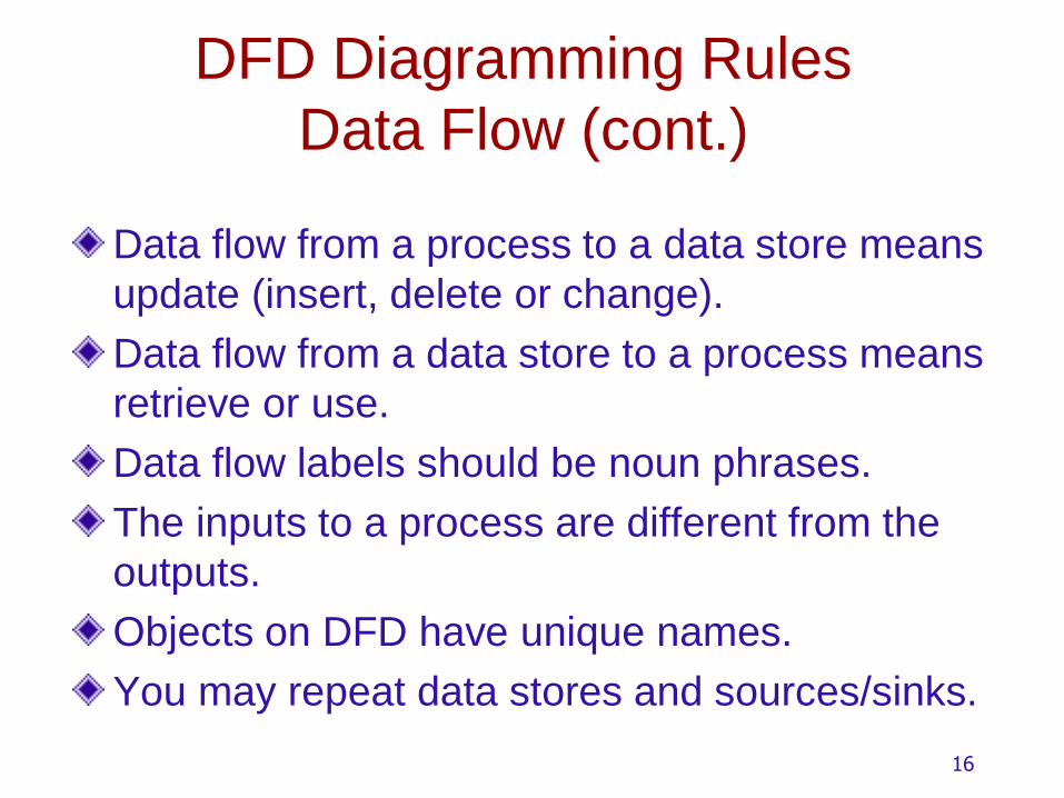
2. Walk through the system in its logical sequence.
A student (EE) sends in an application form (DF)
containing their personal details, and their desired
course
The university checks (P) that the course is
available.
If the course is available the student is enrolled (P)
in the course, and the university confirms (P) the
enrolment by sending a confirmation letter (DF) that
they are registered for the course to the student.
Or if the course is unavailable the student is sent a
rejection letter (DF).

20
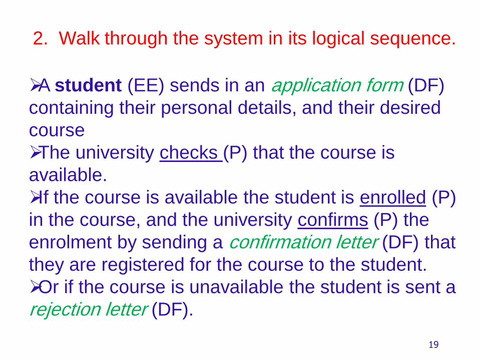
Context diagram
Highest level DFD.
Has data flows, external entities, one process
(system in focus) and no data stores.
Shows the system boundary and interactions with
external entities.
In this case:
External entity - Student
Process - Student Administration
process application
Data Flows - Application Form,
- Confirmation/Rejection Letter
21
StudentAdministration
System
Student
Confirmation/Rejection Details
Application Details
Context diagram
0

22
System/Level 0 DFD
External entity - Student
Processes - Check available
- Enrol student
- Confirm Registration
Data Flows - Application Form
- Course Details
- Course Enrolment Details
- Student Details
- Confirmation/Rejection Letter
Data Stores - Courses
- Students

23
EnrolStudent
CheckCourse
Available
ConfirmRegistered
StudentApplication
Details
Courses
Students
Course Details
Course Details
Course Enrolment Details
Student Details
Co
nfirm
atio
n/R
eje
ctio
n D
eta
ils
RegistrationDetails
Accepted/RejectedSelections
1.0
2.0
3.0
System/Level 0 DFD

24
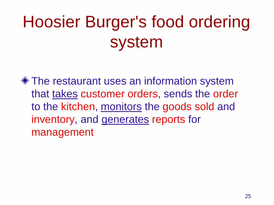
Hoosier Burger's food ordering
system
The restaurant uses an information system
that takes customer orders, sends the order
to the kitchen, monitors the goods sold and
inventory, and generates reports for
management
25
Hoosier Burger's food ordering
system
The restaurant uses an information system
that takes customer orders, sends the order
to the kitchen, monitors the goods sold and
inventory, and generates reports for
management

Context Diagram
Context diagram
shows the
system
boundaries,
external entities
that interact with
the system, and
major
information flows
between entities
and the system.
NOTE: only one process symbol, and no
data stores shown.
26

Level-0 DFD
Level-0 DFD
shows the
system’s major
processes, data
flows, and data
stores at a high
level of
abstraction.
Processes are labeled 1.0, 2.0, etc. These will be decomposed into
more primitive (lower-level) DFDs.
27
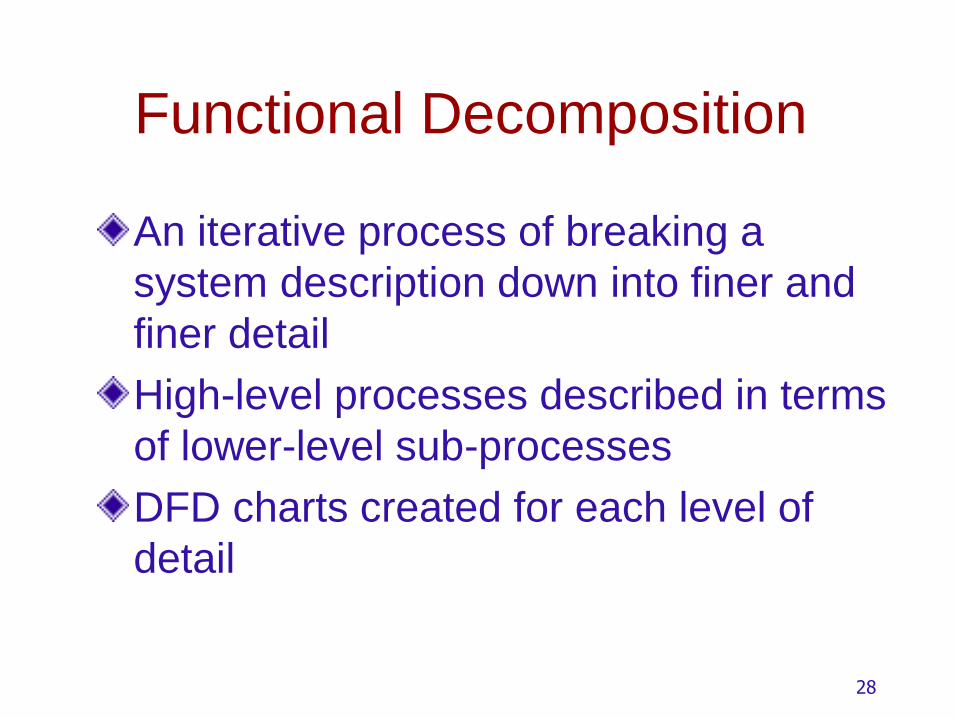
Functional Decomposition
An iterative process of breaking a
system description down into finer and
finer detail
High-level processes described in terms
of lower-level sub-processes
DFD charts created for each level of
detail
28

Level-1 DFD of Receive & Transform Customer
Food Order
Level-1 DFD shows
the sub-processes
of one of the
processes in the
Level-0 DFD.
This is a Level-1
DFD for Process
1.0.
No sources or sinks
Are represented.
Processes are labeled 1.1, 1.2, etc. These can be further
decomposed in more primitive (lower-level) DFDs if necessary.

Decomposition of DFD Level-1 DFD
Level-1 DFD shows
the sub-processes
of one of the
processes in the
Level-0 DFD.
This is a Level-1
DFD for Process
4.0.
No sources or sinks
Are represented.
Processes are labeled 4.1, 4.2, etc. These can be further
decomposed in more primitive (lower-level) DFDs if necessary.
30

Level-n DFD
Level-n DFD shows
the sub-processes
of one of the
processes in the
Level n-1 DFD.
This is a Level-2
DFD for Process
4.3.
Processes are labeled 4.3.1, 4.3.2, etc. If this is the
lowest level of the hierarchy, it is called a primitive DFD.
31

DFD Balancing
The conservation of inputs and outputs to a data flow process when that process is decomposed to a lower level
Balanced means: Number of inputs to lower level DFD equals
number of inputs to associated process of higher-level DFD
Number of outputs to lower level DFD equals number of outputs to associated process of higher-level DFD
32

Unbalanced DFD
This is
unbalanced
because the
process of the
context diagram
has only one
input but the
Level-0 diagram
has two inputs.
1 input
1 output
2 inputs
1 output
33

Balanced DFD
These are balanced because the
numbers of inputs and outputs of
context diagram process equal the
number of inputs and outputs of
Level-0 diagram.
1 input
2 outputs
34
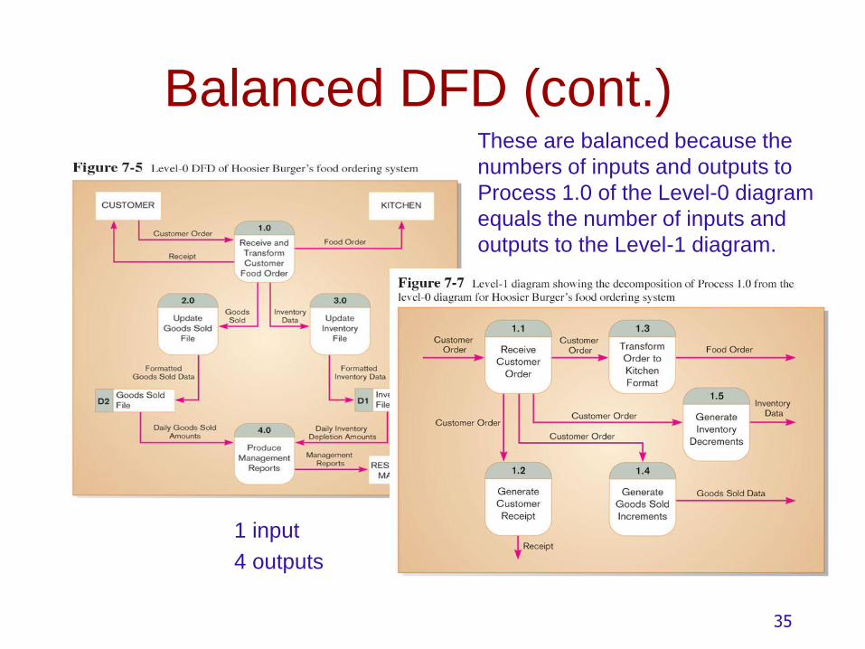
Balanced DFD (cont.) These are balanced because the
numbers of inputs and outputs to
Process 1.0 of the Level-0 diagram
equals the number of inputs and
outputs to the Level-1 diagram.
1 input
4 outputs
35

Data Flow Splitting
A composite data flow at
a higher level may be
split if different parts go
to different processes in
the lower level DFD.
This remains balanced because the same data is involved, but
split into two parts.
36

More DFD Rules
37

38
Four Different Types of DFDs
Current Physical Process labels identify technology (people or
systems) used to process the data.
Data flows and data stores identify actual name of the physical media.
Current Logical Physical aspects of system are removed as much as
possible.
Current system is reduced to data and processes that transform them.

39
Four Different Types of DFDs
(Cont.)
New Logical
Includes additional functions.
Obsolete functions are removed.
Inefficient data flows are reorganized.
New Physical
Represents the physical implementation of
the new system.

Guidelines for Drawing DFDs
Completeness
DFD must include all components necessary for system.
Each component must be fully described in the project dictionary or CASE repository.
Consistency
The extent to which information contained on one level of a set of nested DFDs is also included on other levels.
40
Guidelines for Drawing DFDs
(cont.)
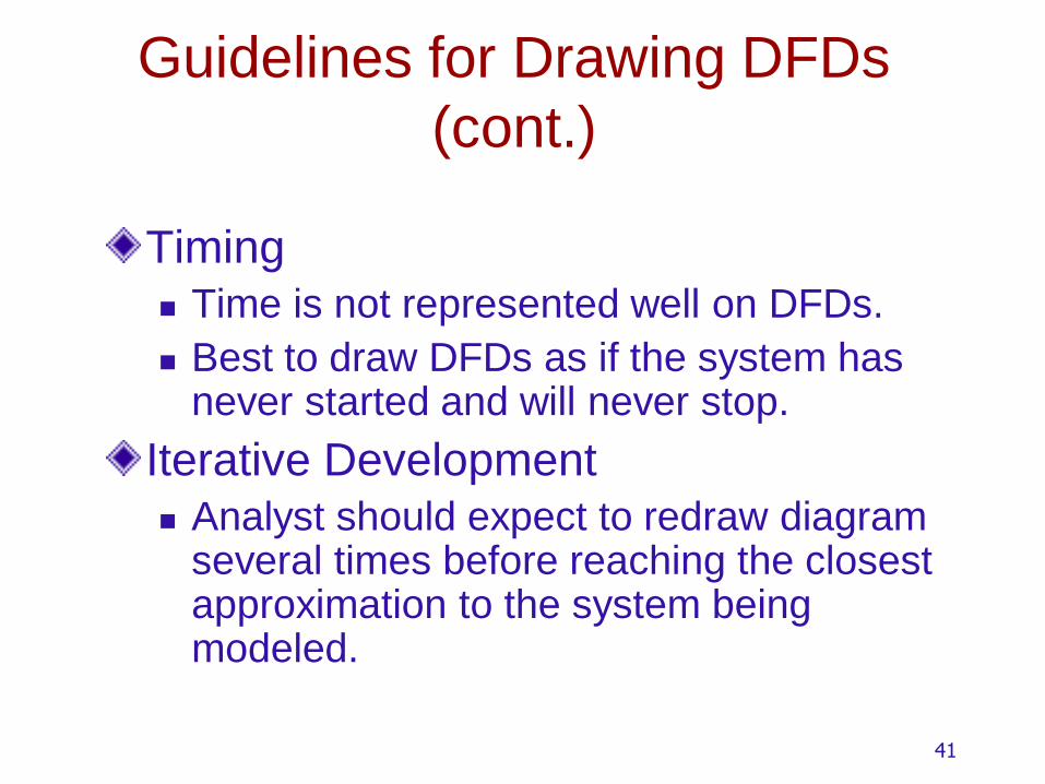
Timing
Time is not represented well on DFDs.
Best to draw DFDs as if the system has never started and will never stop.
Iterative Development
Analyst should expect to redraw diagram several times before reaching the closest approximation to the system being modeled.
41

Guidelines for Drawing DFDs
(cont.)
Primitive DFDs
Lowest logical level of decomposition
Decision has to be made when to stop
decomposition
42

Guidelines for Drawing DFDs
(cont.)
Rules for stopping decomposition
When each process has been reduced to a
single decision, calculation or database
operation (ex. Retrieve, create, delete…).
When each data store represents data
about a single entity (ex. Customer,
employee, order…).
When the system user does not care to
see any more detail or when the analyst
documented sufficient detail.
43

Guidelines for Drawing DFDs
(cont.)
Rules for stopping decomposition (continued)
When every data flow does not need to be split
further to show that data are handled in various
ways
When you believe that you have shown each
business form or transaction, online display and
report as a single data flow
When you believe that there is a separate process
for each choice on all lowest-level menu options
44

Example:Grading System
Al Burns is the professor for the class. He gives the student information to Ms. Grader to create a file of them. He also gives a list of assignments, a description for each assignment, and a grading key for each one to Ms. Grader to create a file of them.
Students complete the assignments and give them to Ms. Grader for grading. Ms. Grader grades the assignments based on a key provided by Al Burns, and assigns a score (grade) from 0 to 5. She then records the scores for the students on the grades file and gives each student his\her grade.
Finally, Ms. Grader prints a report for Al Burns contains students with their grades.
Draw a context diagram and level 0 diagram for the Grading System.

Context diagram
0
GradingSystem
ProfessorStudent
assignment info
student info
grade report
grade info
completed assignment

Level 0
GradesD1
Maintainstudents
student info
Maintainassignments
7
Producegrade report
grade info
Professor
5
Gradeassignment
D2
Assignments
D3
Students
assignment info
Student
1
grade info
student info
assignment info
grade report
3
student
infocompleted
assignment
grade info
assignment
info
1.0
2.0
3.0
4.0

Example: FOX company
FOX company is a mail order company that distributes CDs and tapes at discount prices to members.
When a customer place an order form, the clerk verifies that the sender is a member by checking the MEMBER FILE. If the sender is not a member, the clerk returns the order along with a membership application form. If the customer is a member, the clerk verifies the order item data by checking the ITEM FILE. Then the clerk enters the order data and saves it to the DAIILY ORDERS FILE. At the same time the clerk also prints an invoice and shipping list for each order, which are forwarded to the order processing department for processing there.

Context Diagram
0
Order
System
Customer
Order Processing
department
Order Form
Application Form
Invoice & shipping list

Level-0 DFD
D1
D2
D3