Embed Size (px)
Citation preview
Prevention of Information Mis-translation by aMalicious Gateway in Connected Vehicles
Kyusuk Han and Kang G. Shin
Real-Time Computing LaboratoryEECS/CSE, The University of Michigan
Ann Arbor, MI 48109-2121, U.S.A.{kyusuk,kgshin}@umich.edu
Abstract—As connectivity is becoming a norm for modern ve-hicles, data exchange between in-vehicle components and externalentities is becoming common. However, car makers is concernedabout a third-party’s extraction of their proprietary vehicle data.To address this concern, an intermediate ECU (or a gateway) isintroduced in between internal and external networks to translateproprietary in-vehicle data to rich type data, thus preventing theexposure of raw in-vehicle data. However, the translation reliessolely on the gateway which can be a direct target of cyberattacks, making it difficult to trust the data passed through thegateway. This, in turn, requires authentication of the translateddata. We present a new, effective protocol that provides securecommunications between the vehicle’s internal components andexternal entities against a compromised gateway.
I. INTRODUCTION
Recent advances of in-vehicle technology have paved theway to connect vehicles to the external world. Car makersare adding various connectivity and telematics solutions forpassenger and fleet vehicles. They have also introduced in-tegrated solutions that either use an embedded modem orconnect to the Internet via the driver/passenger’s cellphone(e.g., GM OnStar, Ford Sync). Besides, fleet-solution providersoffer solutions attachable to the vehicle’s on-board diagnostics(OBD2) port (e.g., Delphi Connect and Zubie). As a result,in-vehicle components/subsystems are being connected to anexternal communication channel for remote diagnostics andtriggering on-board functions from a remote site.
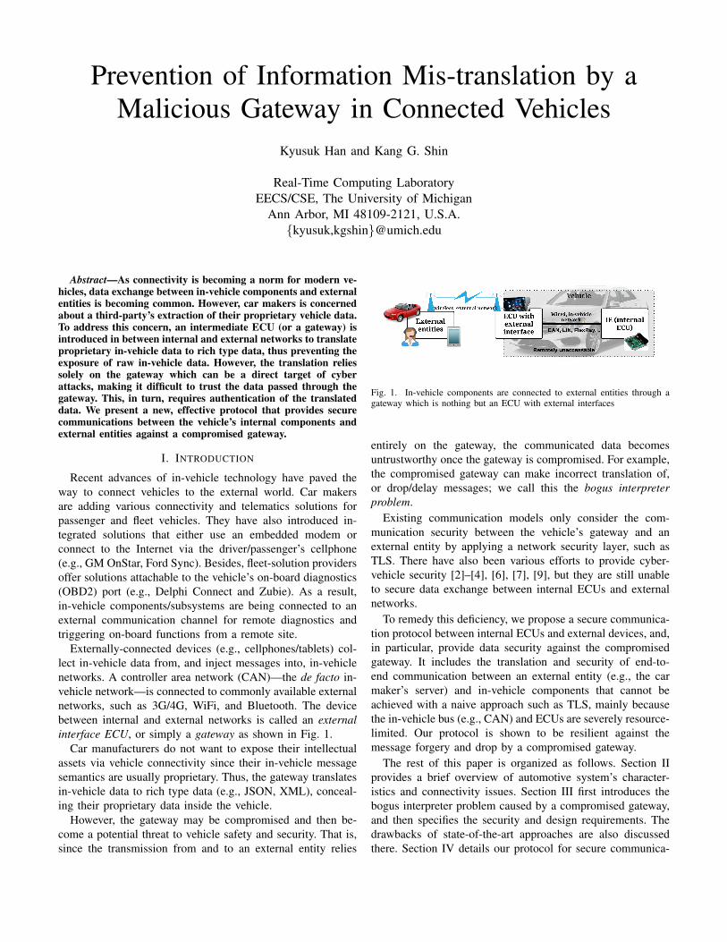
Externally-connected devices (e.g., cellphones/tablets) col-lect in-vehicle data from, and inject messages into, in-vehiclenetworks. A controller area network (CAN)—the de facto in-vehicle network—is connected to commonly available externalnetworks, such as 3G/4G, WiFi, and Bluetooth. The devicebetween internal and external networks is called an externalinterface ECU, or simply a gateway as shown in Fig. 1.
Car manufacturers do not want to expose their intellectualassets via vehicle connectivity since their in-vehicle messagesemantics are usually proprietary. Thus, the gateway translatesin-vehicle data to rich type data (e.g., JSON, XML), conceal-ing their proprietary data inside the vehicle.
However, the gateway may be compromised and then be-come a potential threat to vehicle safety and security. That is,since the transmission from and to an external entity relies
Fig. 1. In-vehicle components are connected to external entities through agateway which is nothing but an ECU with external interfaces
entirely on the gateway, the communicated data becomesuntrustworthy once the gateway is compromised. For example,the compromised gateway can make incorrect translation of,or drop/delay messages; we call this the bogus interpreterproblem.
Existing communication models only consider the com-munication security between the vehicle’s gateway and anexternal entity by applying a network security layer, such asTLS. There have also been various efforts to provide cyber-vehicle security [2]–[4], [6], [7], [9], but they are still unableto secure data exchange between internal ECUs and externalnetworks.
To remedy this deficiency, we propose a secure communica-tion protocol between internal ECUs and external devices, and,in particular, provide data security against the compromisedgateway. It includes the translation and security of end-to-end communication between an external entity (e.g., the carmaker’s server) and in-vehicle components that cannot beachieved with a naive approach such as TLS, mainly becausethe in-vehicle bus (e.g., CAN) and ECUs are severely resource-limited. Our protocol is shown to be resilient against themessage forgery and drop by a compromised gateway.
The rest of this paper is organized as follows. Section IIprovides a brief overview of automotive system’s character-istics and connectivity issues. Section III first introduces thebogus interpreter problem caused by a compromised gateway,and then specifies the security and design requirements. Thedrawbacks of state-of-the-art approaches are also discussedthere. Section IV details our protocol for secure communica-
tion between internal ECUs and external devices. The securityand performance of the proposed protocol are evaluated inSections V and VI, respectively. Finally, the paper concludeswith Section VII.
II. DATA EXCHANGE BETWEEN INTERNAL ANDEXTERNAL ENTITIES
We first briefly describe the characteristics of in-vehiclesystems, and then discuss in-vehicle data exchange modelsand issues.
A. Characteristics of In-vehicle systems
Automotive systems are hard real-time systems, equippedwith various electronic control units (ECUs) which are in-terconnected via wireline networks, such as Controller AreaNetworks (CAN), Local interconnect network (LIN), andFlexray. CAN has become the de facto standard for in-vehicle communications due to its low cost and widespreaddeployment.
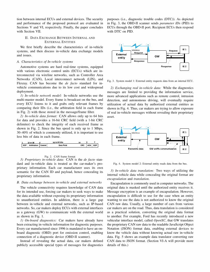
1) In-vehicle network model: In-vehicle networks use themulti-master model. Every frame is broadcast on the bus, andevery ECU listens to it and grabs only relevant frames bycomparing their IDs (i.e., the arbitration field in each framein Fig. 2) with those stored in the message/frame filter.
2) In-vehicle data format: CAN allows only up to 64 bitsfor data and provides a 16-bit CRC field (with a 1-bit CRCdelimiter) to check the integrity of each received frame asshown in Fig. 2. Since the bus speed is only up to 1 Mbps,30–40% of which is commonly utilized, it is important to useless bits of data in each frame.
Fig. 2. CAN frame format3) Proprietary in-vehicle data: CAN is the de facto stan-
dard and in-vehicle data is treated as the car-maker’s pro-prietary information. Each car manufacturer uses its ownsemantic for the CAN ID and payload, hence concealing itsproprietary information.
B. Data exchange between in-vehicle and external networks
The vehicle connectivity requires knowledge of CAN datafor its intended use, forcing car makers to seek ways to makethe data available without exposing its proprietary informationto unauthorized entities. In addition, there is a large gapbetween in-vehicle and external networks, such as IP-basednetworks. So, car makers deploy ECUs with external interfacesas a gateway (GW) to communicate with the external worldas shown in Fig. 1.
1) On-board diagnostics: Car makers have already havebeen extracting in-vehicle information for diagnostic purposes.Every car manufactured since 1996 is mandated to have an on-board diagnostic (OBD) port for emission control, enablingconnection of a diagnostic device (OBD-II scanner).
Instead of revealing the actual data, car makers definedpublicly accessible special types of messages for diagnostics
purposes (i.e., diagnostic trouble codes (DTC)). As depictedin Fig. 3, the OBD-II scanner sends parameter IDs (PID) toECUs through the OBD-II port. Recipient ECUs then respondwith DTC on PID.
Fig. 3. System model 1: External entity requests data from an internal ECU.
2) Exchanging real in-vehicle data: While the diagnosticsmessages are limited to providing the information service,more advanced applications such as remote control, intrusiondetection, and autonomous driving, will eventually requireutilization of actual data by authorized external entities asshown in Fig. 4. Thus, car makers are trying to allow exposureof real in-vehicle messages without revealing their proprietaryasset.
Fig. 4. System model 2: External entity reads data from the bus.
3) In-vehicle data translation: Two ways of utilizing theinternal vehicle data while concealing the original format areencapsulation and translation.
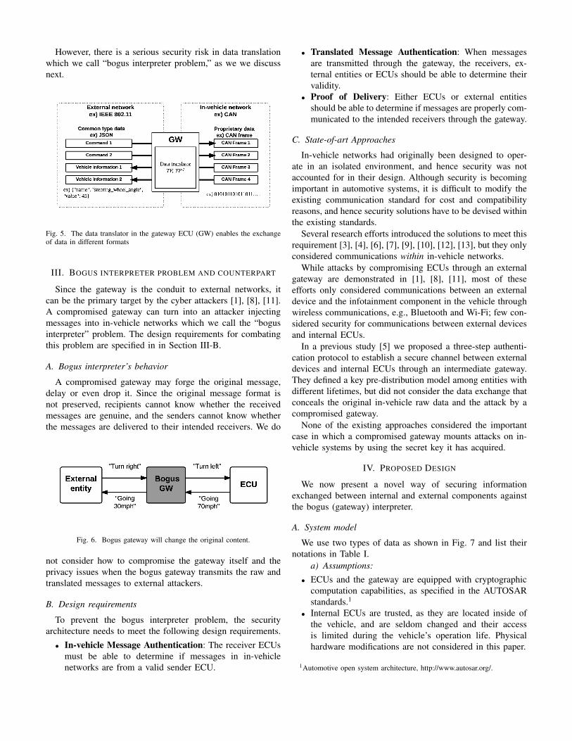
Encapsulation is commonly used in computer networks. Theoriginal data is masked until the authorized entity receives it.Message encryption is an example of encapsulation. However,encapsulation is difficult to use for the case when an entitywanting to use the data is not authorized to know the originalCAN raw data. Usually, a large number of cars from variouscar makers are on the road. Thus, data translation is consideredas a practical solution, converting the original data formatto another. For example, Ford has recently introduced a newvehicular interface model, called OpenXC, that GW translatesthe proprietary CAN raw data to the readable JavaScript ObjectNotation (JSON) format data, enabling external devices toknow the vehicle data without knowing actual raw in-vehicledata. Fig. 5 shows an example data translator converting rawCAN data to JSON format. (Section VI-A will provide moredetails of this.)
However, there is a serious security risk in data translationwhich we call “bogus interpreter problem,” as we we discussnext.
Fig. 5. The data translator in the gateway ECU (GW) enables the exchangeof data in different formats
III. BOGUS INTERPRETER PROBLEM AND COUNTERPART
Since the gateway is the conduit to external networks, itcan be the primary target by the cyber attackers [1], [8], [11].A compromised gateway can turn into an attacker injectingmessages into in-vehicle networks which we call the “bogusinterpreter” problem. The design requirements for combatingthis problem are specified in in Section III-B.
A. Bogus interpreter’s behavior
A compromised gateway may forge the original message,delay or even drop it. Since the original message format isnot preserved, recipients cannot know whether the receivedmessages are genuine, and the senders cannot know whetherthe messages are delivered to their intended receivers. We do
Fig. 6. Bogus gateway will change the original content.
not consider how to compromise the gateway itself and theprivacy issues when the bogus gateway transmits the raw andtranslated messages to external attackers.
B. Design requirements
To prevent the bogus interpreter problem, the securityarchitecture needs to meet the following design requirements.
• In-vehicle Message Authentication: The receiver ECUsmust be able to determine if messages in in-vehiclenetworks are from a valid sender ECU.
• Translated Message Authentication: When messagesare transmitted through the gateway, the receivers, ex-ternal entities or ECUs should be able to determine theirvalidity.
• Proof of Delivery: Either ECUs or external entitiesshould be able to determine if messages are properly com-municated to the intended receivers through the gateway.
C. State-of-art Approaches
In-vehicle networks had originally been designed to oper-ate in an isolated environment, and hence security was notaccounted for in their design. Although security is becomingimportant in automotive systems, it is difficult to modify theexisting communication standard for cost and compatibilityreasons, and hence security solutions have to be devised withinthe existing standards.
Several research efforts introduced the solutions to meet thisrequirement [3], [4], [6], [7], [9], [10], [12], [13], but they onlyconsidered communications within in-vehicle networks.
While attacks by compromising ECUs through an externalgateway are demonstrated in [1], [8], [11], most of theseefforts only considered communications between an externaldevice and the infotainment component in the vehicle throughwireless communications, e.g., Bluetooth and Wi-Fi; few con-sidered security for communications between external devicesand internal ECUs.
In a previous study [5] we proposed a three-step authenti-cation protocol to establish a secure channel between externaldevices and internal ECUs through an intermediate gateway.They defined a key pre-distribution model among entities withdifferent lifetimes, but did not consider the data exchange thatconceals the original in-vehicle raw data and the attack by acompromised gateway.
None of the existing approaches considered the importantcase in which a compromised gateway mounts attacks on in-vehicle systems by using the secret key it has acquired.
IV. PROPOSED DESIGN
We now present a novel way of securing informationexchanged between internal and external components againstthe bogus (gateway) interpreter.
A. System model
We use two types of data as shown in Fig. 7 and list theirnotations in Table I.
a) Assumptions:• ECUs and the gateway are equipped with cryptographic
computation capabilities, as specified in the AUTOSARstandards.1
• Internal ECUs are trusted, as they are located inside ofthe vehicle, and are seldom changed and their accessis limited during the vehicle’s operation life. Physicalhardware modifications are not considered in this paper.
1Automotive open system architecture, http://www.autosar.org/.
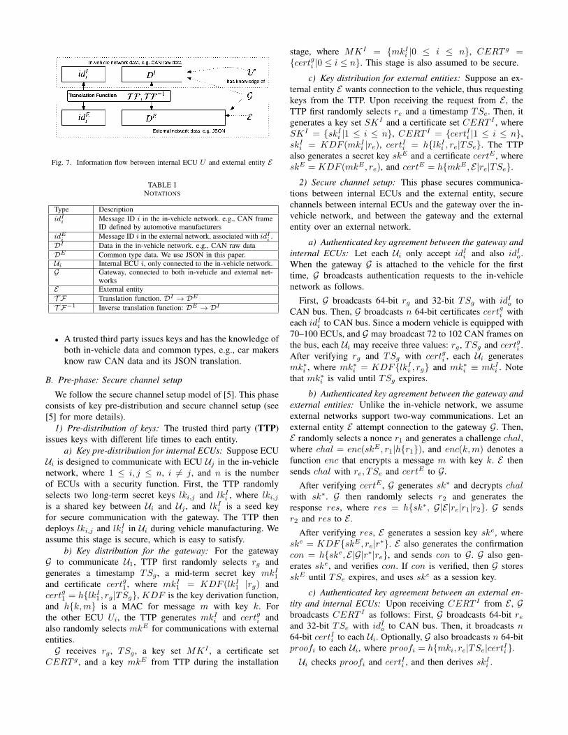
Fig. 7. Information flow between internal ECU U and external entity E
TABLE INOTATIONS
Type DescriptionidIi Message ID i in the in-vehicle network. e.g., CAN frame
ID defined by automotive manufacturersidEi Message ID i in the external network, associated with idIi .DI Data in the in-vehicle network. e.g., CAN raw dataDE Common type data. We use JSON in this paper.Ui Internal ECU i, only connected to the in-vehicle network.G Gateway, connected to both in-vehicle and external net-
worksE External entityT F Translation function. DI ! DE
T F�1 Inverse translation function: DE ! DI
• A trusted third party issues keys and has the knowledge ofboth in-vehicle data and common types, e.g., car makersknow raw CAN data and its JSON translation.
B. Pre-phase: Secure channel setup
We follow the secure channel setup model of [5]. This phaseconsists of key pre-distribution and secure channel setup (see[5] for more details).
1) Pre-distribution of keys: The trusted third party (TTP)issues keys with different life times to each entity.
a) Key pre-distribution for internal ECUs: Suppose ECUU
i
is designed to communicate with ECU Uj
in the in-vehiclenetwork, where 1 i, j n, i 6= j, and n is the numberof ECUs with a security function. First, the TTP randomlyselects two long-term secret keys lk
i,j
and lk
I
i
, where lk
i,j
is a shared key between Ui
and Uj
, and lk
I
i
is a seed keyfor secure communication with the gateway. The TTP thendeploys lk
i,j
and lk
I
i
in Ui
during vehicle manufacturing. Weassume this stage is secure, which is easy to satisfy.
b) Key distribution for the gateway: For the gatewayG to communicate U1, TTP first randomly selects r
g
andgenerates a timestamp TS
g
, a mid-term secret key mk
I
1
and certificate cert
g
1, where mk
I
1 = KDF (lkI
1 |rg
) andcert
g
1 = h{lkI
1 , rg
|TSg
}, KDF is the key derivation function,and h{k,m} is a MAC for message m with key k. Forthe other ECU U
i
, the TTP generates mk
I
i
and cert
g
i
andalso randomly selects mk
E for communications with externalentities.
G receives r
g
, TS
g
, a key set MK
I , a certificate setCERT
g , and a key mk
E from TTP during the installation
stage, where MK
I = {mk
I
i
|0 i n}, CERT
g ={certg
i
|0 i n}. This stage is also assumed to be secure.
c) Key distribution for external entities: Suppose an ex-ternal entity E wants connection to the vehicle, thus requestingkeys from the TTP. Upon receiving the request from E , theTTP first randomly selects r
e
and a timestamp TS
e
. Then, itgenerates a key set SKI and a certificate set CERT
I , whereSK
I = {skI
i
|1 i n}, CERT
I = {certIi
|1 i n},sk
I
i
= KDF (mk
I
i
|re
), cert
I
i
= h{lkI
i
, r
e
|TSe
}. The TTPalso generates a secret key sk
E and a certificate cert
E , wheresk
E = KDF (mk
E
, r
e
), and cert
E = h{mk
E
, E|re
|TSe
}.
2) Secure channel setup: This phase secures communica-tions between internal ECUs and the external entity, securechannels between internal ECUs and the gateway over the in-vehicle network, and between the gateway and the externalentity over an external network.
a) Authenticated key agreement between the gateway andinternal ECUs: Let each U
i
only accept id
I
i
and also id
I
o
.When the gateway G is attached to the vehicle for the firsttime, G broadcasts authentication requests to the in-vehiclenetwork as follows.
First, G broadcasts 64-bit r
g
and 32-bit TS
g
with id
I
o
toCAN bus. Then, G broadcasts n 64-bit certificates cert
g
i
witheach id
I
i
to CAN bus. Since a modern vehicle is equipped with70–100 ECUs, and G may broadcast 72 to 102 CAN frames onthe bus, each U
i
may receive three values: rg
, TSg
and cert
g
i
.After verifying r
g
and TS
g
with cert
g
i
, each Ui
generatesmk
⇤i
, where mk
⇤i
= KDF{lkI
i
, r
g
} and mk
⇤i
⌘ mk
I
i
. Notethat mk
⇤i
is valid until TSg
expires.
b) Authenticated key agreement between the gateway andexternal entities: Unlike the in-vehicle network, we assumeexternal networks support two-way communications. Let anexternal entity E attempt connection to the gateway G. Then,E randomly selects a nonce r1 and generates a challenge chal,where chal = enc(skE
, r1|h{r1}), and enc(k,m) denotes afunction enc that encrypts a message m with key k. E thensends chal with r
e
, TS
e
and cert
E to G.
After verifying cert
E , G generates sk
⇤ and decrypts chal
with sk
⇤. G then randomly selects r2 and generates theresponse res, where res = h{sk⇤, G|E|r
e
|r1|r2}. G sendsr2 and res to E .
After verifying res, E generates a session key sk
e, wheresk
e = KDF{skE
, r
e
|r⇤}. E also generates the confirmationcon = h{ske
, E|G|r⇤|re
}, and sends con to G. G also gen-erates sk
e, and verifies con. If con is verified, then G storessk
E until TSe
expires, and uses sk
e as a session key.
c) Authenticated key agreement between an external en-tity and internal ECUs: Upon receiving CERT
I from E , Gbroadcasts CERT
I as follows: First, G broadcasts 64-bit re
and 32-bit TSe
with id
I
o
to CAN bus. Then, it broadcasts n
64-bit certIi
to each Ui
. Optionally, G also broadcasts n 64-bitproof
i
to each Ui
, where proof
i
= h{mk
i
, r
e
|TSe
|certIi
}.
Ui
checks proof
i
and cert
I
i
, and then derives sk
I
i
.
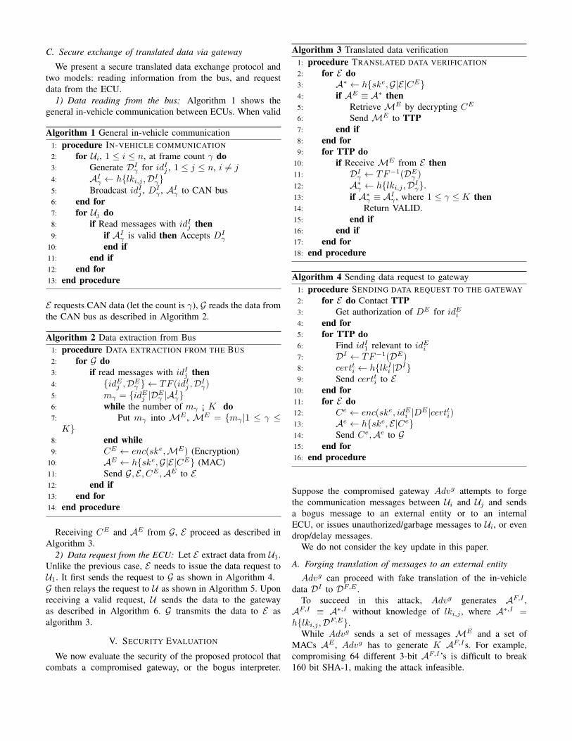
C. Secure exchange of translated data via gateway
We present a secure translated data exchange protocol andtwo models: reading information from the bus, and requestdata from the ECU.
1) Data reading from the bus: Algorithm 1 shows thegeneral in-vehicle communication between ECUs. When valid
Algorithm 1 General in-vehicle communication1: procedure IN-VEHICLE COMMUNICATION2: for U
i
, 1 i n, at frame count � do3: Generate DI
�
for idI
j
, 1 j n, i 6= j
4: AI
�
h{lki,j
,DI
�
}5: Broadcast idI
j
, DI
�
, AI
�
to CAN bus6: end for7: for U
j
do8: if Read messages with id
I
j
then9: if AI
�
is valid then Accepts D
I
�
10: end if11: end if12: end for13: end procedure
E requests CAN data (let the count is �), G reads the data fromthe CAN bus as described in Algorithm 2.
Algorithm 2 Data extraction from Bus1: procedure DATA EXTRACTION FROM THE BUS2: for G do3: if read messages with id
I
j
then4: {idE
j
,DE
�
} TF (idI
j
,DI
�
)5: m
�
= {idE
j
|DE
�
|AI
�
}6: while the number of m
�
¡ K do7: Put m
�
into ME , ME = {m�
|1 � K}
8: end while9: C
E enc(ske
,ME) (Encryption)10: AE h{ske
,G|E|CE} (MAC)11: Send G, E , CE
,AE to E12: end if13: end for14: end procedure
Receiving C
E and AE from G, E proceed as described inAlgorithm 3.
2) Data request from the ECU: Let E extract data from U1.Unlike the previous case, E needs to issue the data request toU1. It first sends the request to G as shown in Algorithm 4.G then relays the request to U as shown in Algorithm 5. Uponreceiving a valid request, U sends the data to the gatewayas described in Algorithm 6. G transmits the data to E asalgorithm 3.
V. SECURITY EVALUATION
We now evaluate the security of the proposed protocol thatcombats a compromised gateway, or the bogus interpreter.
Algorithm 3 Translated data verification1: procedure TRANSLATED DATA VERIFICATION2: for E do3: A⇤ h{ske
,G|E|CE}4: if AE ⌘ A⇤ then5: Retrieve ME by decrypting C
E
6: Send ME to TTP7: end if8: end for9: for TTP do
10: if Receive ME from E then11: DI
�
TF
�1(DE
�
)12: A⇤
�
h{lki,j
,DI
�
}.13: if A⇤
�
⌘ AI
�
, where 1 � K then14: Return VALID.15: end if16: end if17: end for18: end procedure
Algorithm 4 Sending data request to gateway1: procedure SENDING DATA REQUEST TO THE GATEWAY2: for E do Contact TTP3: Get authorization of DE for idE
i
4: end for5: for TTP do6: Find id
I
1 relevant to id
E
i
7: DI TF
�1(DE)8: cert
t
i
h{lkI
i
|DI}9: Send cert
t
i
to E10: end for11: for E do12: C
e enc(ske
, id
E
i
|DE |certti
)13: Ae h{ske
, E|Ce}14: Send C
e
,Ae to G15: end for16: end procedure
Suppose the compromised gateway Adv
g attempts to forgethe communication messages between U
i
and Uj
and sendsa bogus message to an external entity or to an internalECU, or issues unauthorized/garbage messages to U
i
, or evendrop/delay messages.
We do not consider the key update in this paper.
A. Forging translation of messages to an external entity
Adv
g can proceed with fake translation of the in-vehicledata DI to DF,E .
To succeed in this attack, Adv
g generates AF,I ,AF,I ⌘ A⇤,I without knowledge of lk
i,j
, where A⇤,I =h{lk
i,j
,DF,E}.While Adv
g sends a set of messages ME and a set ofMACs AE , Adv
g has to generate K AF,Is. For example,compromising 64 different 3-bit AF,I ’s is difficult to break160 bit SHA-1, making the attack infeasible.

Algorithm 5 Inject data request to ECU1: procedure INJECT REQUEST TO ECU2: for G do3: if Receive C
e
,Ae then4: A⇤ h{ske
, E|Ce}5: if Ae ⌘ A⇤ then6: {idE
i
, D
E
, cert
t
i
} dec{ske
, C
e}7: {idI
i
,DI} TF
�1(idE
i
,DE)8: Ag
i
h{mk
I
i
, id
I
i
|certti
|DI}9: Broadcast idI
i
,DI
, cert
t
i
,Ag
i
10: end if11: end if12: end for13: for U1 do14: if Receive messages with id
I
1 then15: Verify Ag
1 and cert
t
1
16: if Ag
1 and cert
t
1 are valid then17: Accept DI .18: end if19: end if20: end for21: end procedure
Algorithm 6 Data Extraction from ECU1: procedure DATA EXTRACTION FROM ECU2: for U1 do3: if Receive authorized request from E then4: Generate DI
5: Ae h{lkI |DI}6: Ag h{mk
I |DI |Ae}7: Broadcast idI
g
|DI
,Ae
,Ag to CAN bus8: end if9: end for
10: for G do11: if Ag is valid then12: DE TF (DI)13: CE enc(ske
, id
E
1 |DE |Ae)14: AE h{ske
, CE}15: Send CE
,AE to E16: end if17: end for18: end procedure
B. Forging translation of messages to an internal ECU
Adv
g may forge the information from E and send the faketranslation DF,I to U
i
. To mount this attack, Adv
g has togenerate a 16 or 32-bit cert
F without knowing lk
I
i
, wherecert
F ⌘ cert
t
i
and cert
t
i
= h{lkI
i
|DF,I}. Thus, this attack ispractically infeasible.
C. Inject bogus messages in the in-vehicle network
Adv
g may attempt to generate and send fake information toU
i
. In this attack, Advg can generate the fake message DF,I
and cert
F . However, as in the previous case, Adv
g also has
to generate cert
F without knowing lk
i,j
, making the attackpractically infeasible.
D. Dropping messages
Adv
g may attempt to drop messages between E and Ui
.Internal ECUs cannot notice if Adv
g dropped messages, butE can notice if the attack is mounted. For example, E has arule that it receives messages from G periodically, or receivesresponse upon request within a certain time.
VI. PERFORMANCE EVALUATION
We now evaluate the performance of the proposed protocol.
A. Evaluation setup
Since CAN data are proprietary for car manufacturersand hence unavailable, we designed our own CAN frameformat, called RTCL-CAN, based on the public informationmade available by Ford Motor Company.2 Table II lists theCAN frame definitions of RTCL-CAN. RTCL-CAN defines19 types of information including steering wheel angle, torqueat transmission, engine speed, and so on.
Each data in RTCL-CAN can be translated to/from JSONby the gateway G and TTP using TF and TF
�1. Next, wepresent an illustrative example of translation.
1) A CAN translation example: As shown in Table II, aframe for controlling the transmission gear position has CANID 0x06 and 4-bit data. It has 8 different states as shownin Table III. Note the translation rule in this table is onlyfor illustration, and the actual rules are proprietary to vehiclemanufacturers and hence unavailable.
Fig. 8 shows how CAN raw data of the transmission gearposition is set to ‘sixth.’ In the raw CAN data Di, SOFand EOF fields are fixed, and RTR is also set to ‘0’ for adata frame. ID ‘00000000110’ indicates that the frame is forthe transmission gear position. Data field contains ‘0110’ andMAC.
0 00000000110 0 000011 0110 1001011000100110 1101111100000110 00 1111111CAN raw data
Identifier Data A_{GW} CRCSOF RTR CTL ACK EOF
{{transmission_gear_position}, {sixth}, {#9626}}Translated
data(JSON)
Di
Do
Fig. 8. Example CAN translation: transmission gear position at ‘sixth’
G converts DI to the translated format DE . G translates thedata with ‘transmission gear position’, ‘sixth’ using TableIII and AI .
When E sends a command {{transmission gear
position}, {neutral}} to G, G translates it to ‘0x006’ and‘0000’.
2http://www.openxcplatform.com
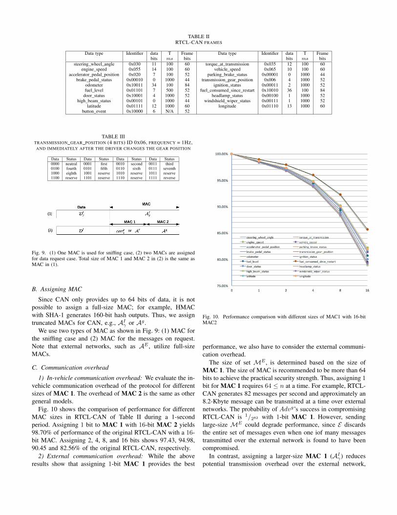
TABLE IIRTCL-CAN FRAMES
Data type Identifier data T Frame Data type Identifier data T Framebits ms bits bits ms bits
steering wheel angle 0x030 11 100 60 torque at transmission 0x035 12 100 60engine speed 0x055 14 100 60 vehicle speed 0x065 10 100 60
accelerator pedal position 0x020 7 100 52 parking brake status 0x00001 0 1000 44brake pedal status 0x00010 0 1000 44 transmission gear position 0x006 4 1000 52
odometer 0x10011 34 100 84 ignition status 0x00011 2 1000 52fuel level 0x01101 7 500 52 fuel consumed since restart 0x10010 36 100 84
door status 0x10001 4 1000 52 headlamp status 0x00100 1 1000 52high beam status 0x00101 0 1000 44 windshield wiper status 0x00111 1 1000 52
latitude 0x01111 12 1000 60 longitude 0x01110 13 1000 60button event 0x10000 6 N/A 52
TABLE IIITRANSMISSION GEAR POSITION (4 BITS) ID 0X06, FREQUENCY = 1HZ,AND IMMEDIATELY AFTER THE DRIVER CHANGES THE GEAR POSITION
Data Status Data Status Data Status Data Status0000 neutral 0001 first 0010 second 0011 third0100 fourth 0101 fifth 0110 sixth 0111 seventh1000 eighth 1001 reserve 1010 reserve 1011 reserve1100 reserve 1101 reserve 1110 reserve 1111 reverse
Fig. 9. (1) One MAC is used for sniffing case, (2) two MACs are assignedfor data request case. Total size of MAC 1 and MAC 2 in (2) is the same asMAC in (1).
B. Assigning MAC
Since CAN only provides up to 64 bits of data, it is notpossible to assign a full-size MAC; for example, HMACwith SHA-1 generates 160-bit hash outputs. Thus, we assigntruncated MACs for CAN, e.g., AI
�
or Ag .We use two types of MAC as shown in Fig. 9: (1) MAC for
the sniffing case and (2) MAC for the messages on request.Note that external networks, such as AE , utilize full-sizeMACs.
C. Communication overhead
1) In-vehicle communication overhead: We evaluate the in-vehicle communication overhead of the protocol for differentsizes of MAC 1. The overhead of MAC 2 is the same as othergeneral models.
Fig. 10 shows the comparison of performance for differentMAC sizes in RTCL-CAN of Table II during a 1-secondperiod. Assigning 1 bit to MAC 1 with 16-bit MAC 2 yields98.70% of performance of the original RTCL-CAN with a 16-bit MAC. Assigning 2, 4, 8, and 16 bits shows 97.43, 94.98,90.45 and 82.56% of the original RTCL-CAN, respectively.
2) External communication overhead: While the aboveresults show that assigning 1-bit MAC 1 provides the best
Fig. 10. Performance comparison with different sizes of MAC1 with 16-bitMAC2
performance, we also have to consider the external communi-cation overhead.
The size of set ME , is determined based on the size ofMAC 1. The size of MAC is recommended to be more than 64bits to achieve the practical security strength. Thus, assigning 1bit for MAC 1 requires 64 n at a time. For example, RTCL-CAN generates 82 messages per second and approximately an8.2-Kbyte message can be transmitted at a time over externalnetworks. The probability of Adv
g’s success in compromisingRTCL-CAN is 1
/282 with 1-bit MAC 1. However, sendinglarge-size ME could degrade performance, since E discardsthe entire set of messages even when one iof many messagestransmitted over the external network is found to have beencompromised.
In contrast, assigning a larger-size MAC 1 (AI
�
) reducespotential transmission overhead over the external network,
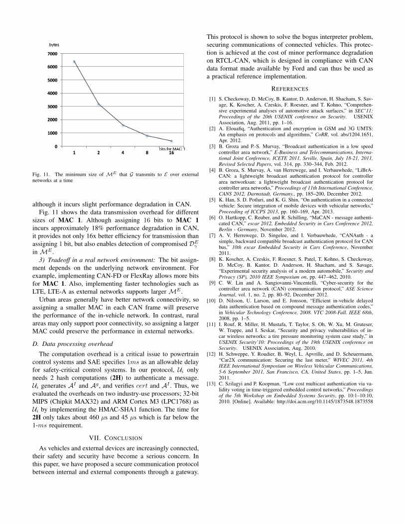
Fig. 11. The minimum size of ME that G transmits to E over externalnetworks at a time
although it incurs slight performance degradation in CAN.Fig. 11 shows the data transmission overhead for different
sizes of MAC 1. Although assigning 16 bits to MAC 1incurs approximately 18% performance degradation in CAN,it provides not only 16x better efficiency for transmission thanassigning 1 bit, but also enables detection of compromised DE
�
in ME .3) Tradeoff in a real network environment: The bit assign-
ment depends on the underlying network environment. Forexample, implementing CAN-FD or FlexRay allows more bitsfor MAC 1. Also, implementing faster technologies such asLTE, LTE-A as external networks supports larger ME .
Urban areas generally have better network connectivity, soassigning a smaller MAC in each CAN frame will preservethe performance of the in-vehicle network. In contrast, ruralareas may only support poor connectivity, so assigning a largerMAC could preserve the performance in external networks.
D. Data processing overhead
The computation overhead is a critical issue to powertraincontrol systems and SAE specifies 1ms as an allowable delayfor safety-critical control systems. In our protocol, U
i
onlyneeds 2 hash computations (2H) to authenticate a message.U
i
generates AI and Ag , and verifies cert and AI . Thus, weevaluated the overheads on two industry-use processors; 32-bitMIPS (Chipkit MAX32) and ARM Cortex M3 (LPC1768) asU
i
by implementing the HMAC-SHA1 function. The time for2H only takes about 460 µs and 45 µs which is far below the1-ms requirement.
VII. CONCLUSION
As vehicles and external devices are increasingly connected,their safety and security have become a serious concern. Inthis paper, we have proposed a secure communication protocolbetween internal and external components through a gateway.
This protocol is shown to solve the bogus interpreter problem,securing communications of connected vehicles. This protec-tion is achieved at the cost of minor performance degradationon RTCL-CAN, which is designed in compliance with CANdata format made available by Ford and can thus be used asa practical reference implementation.
REFERENCES
[1] S. Checkoway, D. McCoy, B. Kantor, D. Anderson, H. Shacham, S. Sav-age, K. Koscher, A. Czeskis, F. Roesner, and T. Kohno, “Comprehen-sive experimental analyses of automotive attack surfaces,” in SEC’11:Proceedings of the 20th USENIX conference on Security. USENIXAssociation, Aug. 2011, pp. 1–16.
[2] A. Elouafiq, “Authentication and encryption in GSM and 3G UMTS:An emphasis on protocols and algorithms,” CoRR, vol. abs/1204.1651,Apr. 2012.
[3] B. Groza and P.-S. Murvay, “Broadcast authentication in a low speedcontroller area network,” E-Business and Telecommunications, Interna-tional Joint Conference, ICETE 2011, Seville, Spain, July 18-21, 2011,Revised Selected Papers, vol. 314, pp. 330–344, Feb. 2012.
[4] B. Groza, S. Murvay, A. van Herrewege, and I. Verbauwhede, “LiBrA-CAN: a lightweight broadcast authentication protocol for controllerarea networksan: a lightweight broadcast authentication protocol forcontroller area networks,” Proceedings of 11th International Conference,CANS 2012, Darmstadt, Germany., pp. 185–200, December 2012.
[5] K. Han, S. D. Potluri, and K. G. Shin, “On authentication in a connectedvehicle: Secure integration of mobile devices with vehicular networks,”Proceeding of ICCPS 2013, pp. 160–169, Apr. 2013.
[6] O. Hartkopp, C. Reuber, and R. Schilling, “MaCAN - message authenti-cated CAN,” escar 2012, Embedded Security in Cars Conference 2012,Berlin - Germany, November 2012.
[7] A. V. Herrewege, D. Singelee, and I. Verbauwhede, “CANAuth - asimple, backward compatible broadcast authentication protocol for CANbus,” 10th escar Embedded Security in Cars Conference, November2011.
[8] K. Koscher, A. Czeskis, F. Roesner, S. Patel, T. Kohno, S. Checkoway,D. McCoy, B. Kantor, D. Anderson, H. Shacham, and S. Savage,“Experimental security analysis of a modern automobile,” Security andPrivacy (SP), 2010 IEEE Symposium on, pp. 447–462, 2010.
[9] C. W. Lin and A. Sangiovanni-Vincentelli, “Cyber-security for thecontroller area network (CAN) communication protocol,” ASE ScienceJournal, vol. 1, no. 2, pp. 80–92, December 2012.
[10] D. Nilsson, U. Larson, and E. Jonsson, “Efficient in-vehicle delayeddata authentication based on compound message authentication codes,”in Vehicular Technology Conference, 2008. VTC 2008-Fall. IEEE 68th,2008, pp. 1–5.
[11] I. Rouf, R. Miller, H. Mustafa, T. Taylor, S. Oh, W. Xu, M. Gruteser,W. Trappe, and I. Seskar, “Security and privacy vulnerabilities of in-car wireless networks: a tire pressure monitoring system case study,” inUSENIX Security’10: Proceedings of the 19th USENIX conference onSecurity. USENIX Association, Aug. 2010.
[12] H. Schweppe, Y. Roudier, B. Weyl, L. Apvrille, and D. Scheuermann,“Car2X communication: Securing the last meter,” WIVEC 2011, 4thIEEE International Symposium on Wireless Vehicular Communications,5-6 September 2011, San Francisco, CA, United States, pp. 1–5, Jun.2011.
[13] C. Szilagyi and P. Koopman, “Low cost multicast authentication via va-lidity voting in time-triggered embedded control networks,” Proceedingsof the 5th Workshop on Embedded Systems Security, pp. 10:1–10:10,2010. [Online]. Available: http://doi.acm.org/10.1145/1873548.1873558