Embed Size (px)
Citation preview
Pressure Vessel Newsletter January 2014 ♦ 1
Pressure Vessel NewsletterPressure Vessel NewsletterPressure Vessel NewsletterPressure Vessel Newsletter Volume 2014, January Issue
Serving the Pressure Vessel Community Since 2007Serving the Pressure Vessel Community Since 2007Serving the Pressure Vessel Community Since 2007Serving the Pressure Vessel Community Since 2007

Pressure Vessel Newsletter January 2014 ♦ 3
From The Editor’s Desk:
Welcome to the New Year. We are glad to launch the first
newsletter for 2014 in a new format. Our mission has always
been to contribute to the continuing education by providing
interesting articles on subjects related to pressure vessels. While
we will continue to serve that mission, we also plan to
supplement the articles with the industry news and with
information related to upcoming conferences and exhibitions.
We also plan to undertake several initiatives that will prove useful
to our readers and their respective organizations.
One such initiative will be tailored for Micro, Small and Medium
Enterprises (MSME) who would like to showcase themselves to
our readers via the newsletter. Our definition of MSME is those
companies that are engaged in pressure vessel related activities
and have employee strength of 50 or less. If your organization
qualifies, then you may send a small write up (no pictures please)
of no more than half a page. For every issue of the newsletter, we
will randomly select one submission and display the write up in
the newsletter.
Another initiative we are planning on is to create a directory of
companies and individual consultants that are engaged in
pressure vessel related activities. Such directories are not so
easily available in all parts of the world. Elsewhere in this issue,
we have listed the information to be provided for inclusion in the
pressure vessel directory. If you would like your company or
yourself to be listed in the directory, please supply the requested
information. The first directory will be made available to the
readers in the first newsletter of 2015.
We would also like to request the readers to supply images to be
displayed on the cover page of the newsletter. If your images are
displayed, it will be accompanied by a proper credit on the inside
pages.
With these announcements, we once again welcome you to the
New Year. Hope you enjoy this issue, and we eagerly look
forward to your feedbacks on this and previous newsletters.
In this issue… Stresses in Pressure Vessels Page 5 Acoustic Emission Examination of Metal Pressure Vessels Page 12 For any queries regarding the newsletter, please write to [email protected] or call at +91 98109 33550 Photograph on the cover is courtesy of freedigitalphoto.net
Pressure Vessel Newsletter January 2014 ♦ 4
Rajiv Mukherjee
Heat Transfer Consultant
New Delhi, India
Based upon my experience of over 42 years in the thermal design of air-cooled and shell-and-tube heat
exchangers (32 years with Engineers India and over 10 years as an independent consultant) and my license to
use HTRI software, I offer the following services at a very competitive cost:
1. Perform/review heat exchanger thermal design at the proposal stage to help you cut your bid costs.
2. Perform/review heat exchanger thermal design during the Detailed Engineering stage. Even though the
responsibility of thermal design can be passed on to a Heat Exchanger supplier, you may find it convenient to
have a 'Reference Design' to help you compare bids from vendors. Alternatively, you may like to have
the vendor's final thermal designs corroborated by me.
3. Troubleshooting heat exchangers and heat exchanger networks. I have carried out several such studies for
many clients during the last several years.
4. Conduct an in-house training program in heat exchanger thermal design and troubleshooting that can be
customized to suit your requirements. I have conducted such a 3-day program over 90 times in the last 10
years.
If your company does not have a strong core competency in heat exchanger thermal design, my services may
significantly enhance your capabilities at a cost significantly lower than what it will cost you otherwise.
Some of the major clients I have worked for are McDermott Houston and Singapore, Alberta Exchanger
Edmonton, HEI Indonesia, DUSUP Dubai, Tebodin Muscat, Worley Parsons Muscat, Petrofac Sharjah and Abu
Dhabi, CBI Lummus, Petronas Malaysia, Petrochina Jakarta, Tripatra Engineering Jakarta, Mott McDonald Abu
Dhabi, KOC Kuwait, Essar Oil, Indian Oil, Hindustan Petroleum, Technip and Aker Solutions.
I have written many papers in Chemical Engineering Progress and Hydrocarbon Processing and the following two
books authored by me were published by Begell House in Connecticut, USA:
• Practical Thermal Design of Shell-and-Tube Heat Exchangers, 2004 and
• Practical Thermal Design of Air-Cooled Heat Exchangers, 2007.
Please e-mail me at [email protected] or call me at +91-11-2551 8281 (work/home) or +91-98711
20126 (cellphone) to discuss how I can serve your company.
Pressure Vessel Newsletter January 2014 ♦ 5
STRESSES IN PRESSURE VESSELS
Introduction
The main purpose of pressure vessels is to contain fluid under pressure and temperature; however, in doing
so they are also subjected to the action of steady and dynamic support loadings, piping reactions, and
thermal shocks which require an overall knowledge of the stresses imposed by these conditions of the
pressure vessel, and appropriate design means to ensure safe and long life.
When shells are formed from plate in which the thickness is small in comparison with other dimensions, and
as such offer little resistance to bending perpendicular to their surface, they are called “membranes”, and the
stresses calculated by neglecting bending are called “membrane stresses”. In one sense, this is a desirable
condition for it permits the vessel to deform readily without incurring large bending stresses at points of
discontinuity. Membrane stresses are average tension or compression stresses over the thickness of vessel
wall and are considered to act tangent to its surface.
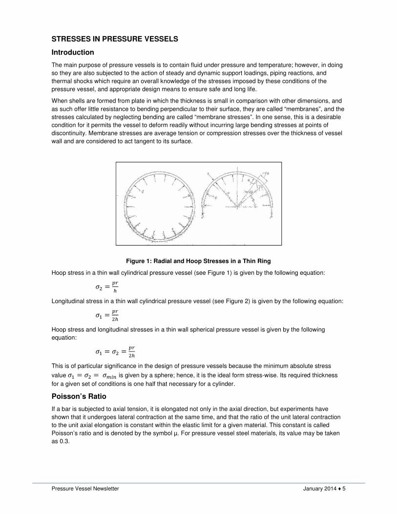
Figure 1: Radial and Hoop Stresses in a Thin Ring
Hoop stress in a thin wall cylindrical pressure vessel (see Figure 1) is given by the following equation:
�� � ���
Longitudinal stress in a thin wall cylindrical pressure vessel (see Figure 2) is given by the following equation:
�� � ����
Hoop stress and longitudinal stresses in a thin wall spherical pressure vessel is given by the following
equation:
�� � �� � ����
This is of particular significance in the design of pressure vessels because the minimum absolute stress
value �� � �� ��� is given by a sphere; hence, it is the ideal form stress-wise. Its required thickness
for a given set of conditions is one half that necessary for a cylinder.
Poisson’s Ratio
If a bar is subjected to axial tension, it is elongated not only in the axial direction, but experiments have
shown that it undergoes lateral contraction at the same time, and that the ratio of the unit lateral contraction
to the unit axial elongation is constant within the elastic limit for a given material. This constant is called
Poisson’s ratio and is denoted by the symbol µ. For pressure vessel steel materials, its value may be taken
as 0.3.
Pressure Vessel Newsletter January 2014 ♦ 6
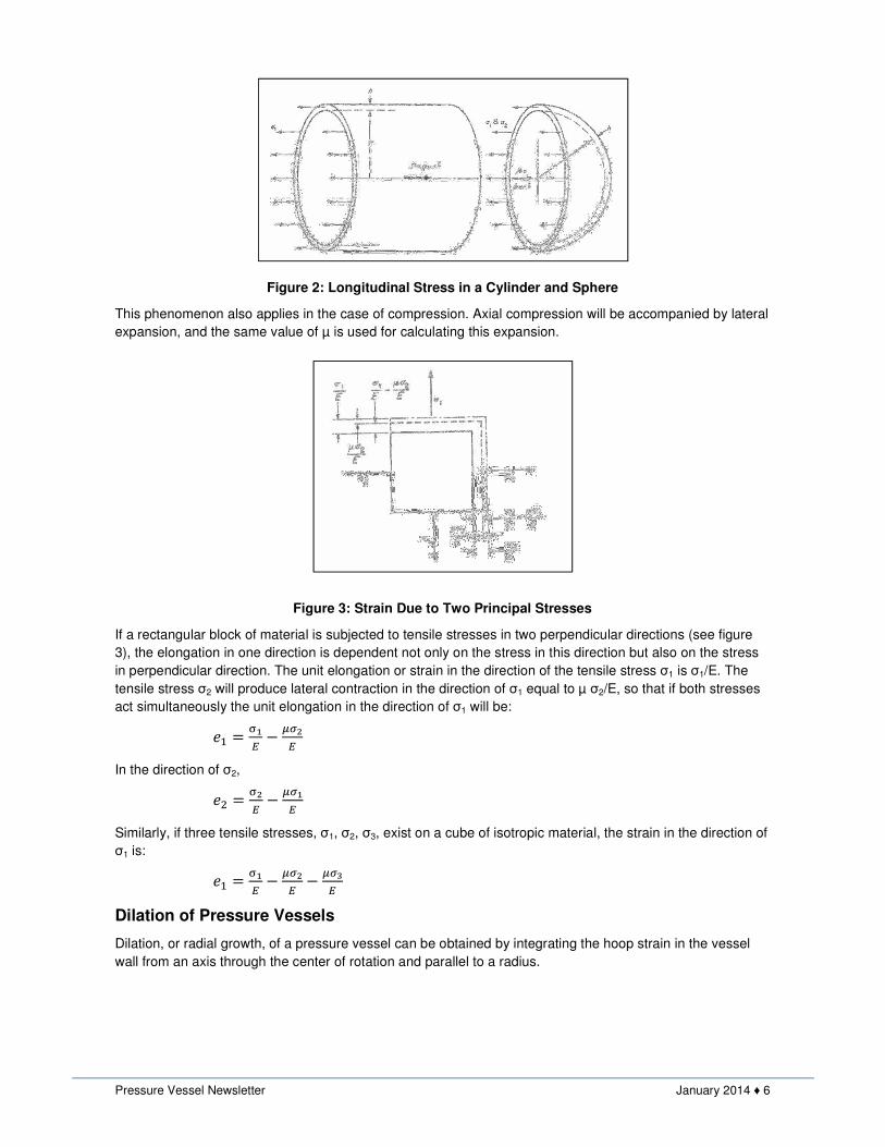
Figure 2: Longitudinal Stress in a Cylinder and Sphere
This phenomenon also applies in the case of compression. Axial compression will be accompanied by lateral
expansion, and the same value of µ is used for calculating this expansion.
Figure 3: Strain Due to Two Principal Stresses
If a rectangular block of material is subjected to tensile stresses in two perpendicular directions (see figure
3), the elongation in one direction is dependent not only on the stress in this direction but also on the stress
in perpendicular direction. The unit elongation or strain in the direction of the tensile stress σ1 is σ1/E. The
tensile stress σ2 will produce lateral contraction in the direction of σ1 equal to µ σ2/E, so that if both stresses
act simultaneously the unit elongation in the direction of σ1 will be:
�� � �� � ���
�
In the direction of σ2,
�� � �� � ���
�
Similarly, if three tensile stresses, σ1, σ2, σ3, exist on a cube of isotropic material, the strain in the direction of
σ1 is:
�� � �� � ���
� � ����
Dilation of Pressure Vessels
Dilation, or radial growth, of a pressure vessel can be obtained by integrating the hoop strain in the vessel
wall from an axis through the center of rotation and parallel to a radius.

Pressure Vessel Newsletter January 2014 ♦ 7
Figure 4: Dilation of Vessel Due to Internal Pressure
The dilation of a cylindrical vessel is given as:
� � ������ �2 � ��
And the dilation of a spherical vessel is given as:
� � ������ �1 � ��
Likewise, the growth of a conical vessel can be found to be:
� � ���������� �2 � ��
The equatorial dilation of an ellipsoidal vessel is,
� � ����� �1 �
��� � �
���
The equatorial dilation is not always positive or outward from the center, as with cylinder or a sphere, but
may be inward depending on a/b ratio. For instance, if the vessel material is steel which has Poisson’s Ratio
µ = 0.3, the equatorial dilation will be negative, or inward for a/b > 1.3. It is this behavior that causes an
increase in the discontinuity stresses when ellipsoidal heads are used instead of hemispherical ones for end
closures on cylindrical shells of equal thickness.
General Theory of Membrane Stresses in Vessels under Internal Pressure
The membrane stresses in vessels of revolution, including those of complicated geometry, can be evaluated
from the equations of statics provided they are loaded in a rotationally symmetrical manner – the pressure
loading need not be same everywhere in the vessel but only on any plane perpendicular to the axis of
rotation 0-0, Figure 5.
In the figure if an element abef is cut by two meridional sections, ab and ef, and by two sections ae and bf
normal to these meridians, it is seen that a condition of symmetry exists and only normal stresses act on the
sides of these element. Let:
σ1 = longitudinal or meridional stress (stress in the meridional direction)
σ2 = hoop stress (hoop stress along a parallel circle)
h = thickness of vessel
ds1 = element dimension in the meridional direction (face ab and ef)
ds2 = element dimension in the hoop direction (face ae and bf)
r1 = longitudinal or meridional radius of curvature
r2 = radius of curvature of the element in the hoop direction (perpendicular to the
meridian)
p = pressure
Pressure Vessel Newsletter January 2014 ♦ 8
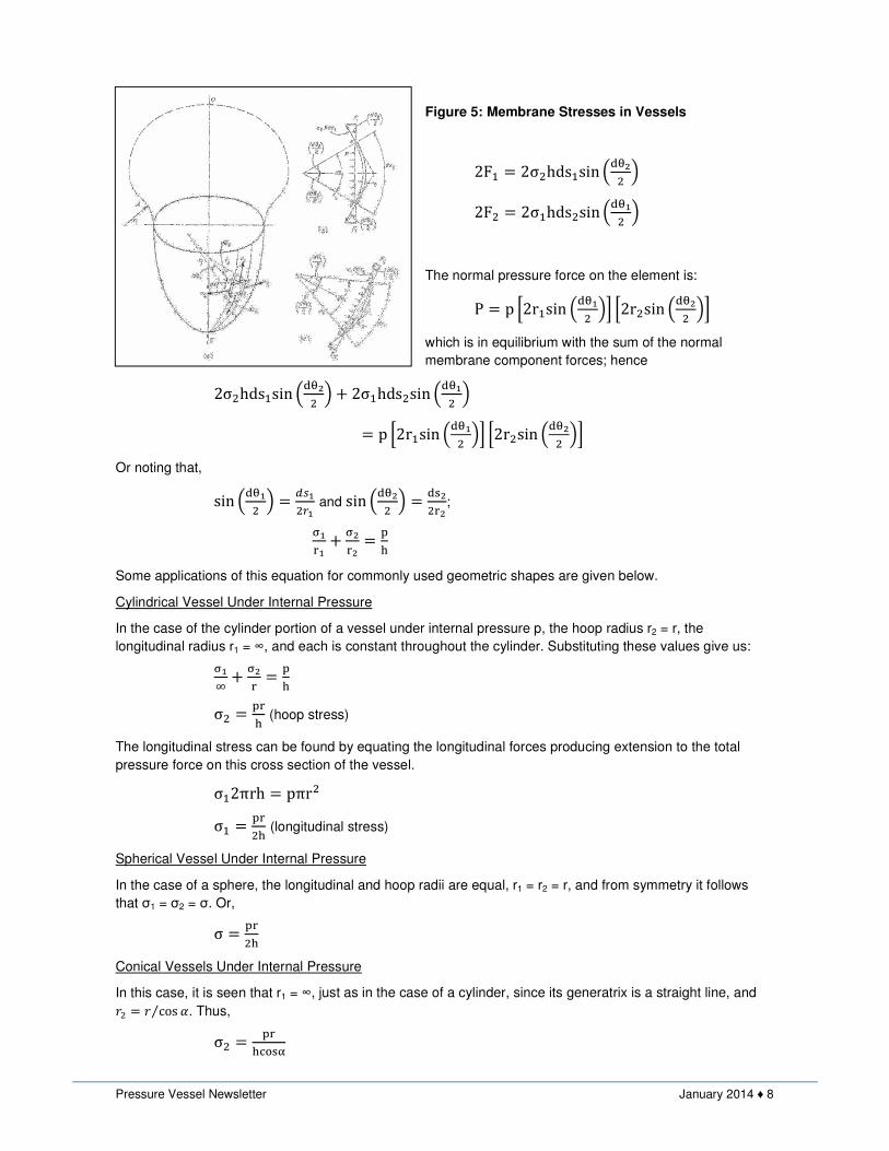
Figure 5: Membrane Stresses in Vessels
2F� � 2σ�hds�sin ()*�� +
2F� � 2σ�hds�sin ()*�� +
The normal pressure force on the element is:
P � p .2r�sin ()*�� +0 .2r�sin ()*�� +0
which is in equilibrium with the sum of the normal
membrane component forces; hence
2σ�hds�sin ()*�� + 1 2σ�hds�sin ()*�� +
� p .2r�sin ()*�� +0 .2r�sin ()*�� +0
Or noting that,
sin ()*�� + �2�����
and sin ()*�� + �)3��4�
;
�4�1 �
4�� 5
6
Some applications of this equation for commonly used geometric shapes are given below.
Cylindrical Vessel Under Internal Pressure
In the case of the cylinder portion of a vessel under internal pressure p, the hoop radius r2 = r, the
longitudinal radius r1 = ∞, and each is constant throughout the cylinder. Substituting these values give us:
�7 1 �
4 � 56
σ� � 546 (hoop stress)
The longitudinal stress can be found by equating the longitudinal forces producing extension to the total
pressure force on this cross section of the vessel.
σ�2πrh � pπr�
σ� � 54�6 (longitudinal stress)
Spherical Vessel Under Internal Pressure
In the case of a sphere, the longitudinal and hoop radii are equal, r1 = r2 = r, and from symmetry it follows
that σ1 = σ2 = σ. Or,
σ � 54�6
Conical Vessels Under Internal Pressure
In this case, it is seen that r1 = ∞, just as in the case of a cylinder, since its generatrix is a straight line, and
9� � 9 cos <⁄ . Thus,
σ� � 546>?3@

Pressure Vessel Newsletter January 2014 ♦ 9
from which it can be seen that 1) the hoop stress approaches that in a cylinder as α approaches zero, and 2)
the stress becomes infinitely large as α approaches 90o and the cone flattens out into a plate. The latter
merely verifies the assumption that a flat membrane cannot take loads perpendicular to its plane.
The longitudinal stress can be found by equating the axial component of this force in the vessel wall to the
total pressure force on a plane perpendicular to the axis of revolution:
σ�h2πrcosα � pπr� σ� � 54
�6>?3@
Ellipsoidal Vessel Under Internal Pressure
Ellipsoidal shaped heads are frequently used for the end closure of cylindrical shells for steam boilers,
reactors and storage vessels in order to accommodate special space or volume requirements. In such
constructions, a half of an ellipsoid is used (see Figure 6). Since the radius of curvature varies from point to
point, the solution becomes somewhat more complicated than for those geometric shapes of constant radii.
Figure 6: Stress in an Ellipsoid
It can be shown that for ellipsoidal heads under internal pressure, the longitudinal stress (σ1) and hoop
stress (σ2) are given by following equations:
σ� � 54��6 , and
σ� � 56 (r� �
4���4�+
At the crown, r1 = r2 = a� b⁄ , and σ� � σ� � 5D��E6
At the equator, r1 = b� a⁄ and r2 = a, and σ� � 5D�6 which is the same as the longitudinal stress in a cylinder,
while σ� � 5D6 (1 �
D��E�+ and it is seen that the hoop stress becomes compressive if a/b > 1.42. As the a/b
ratio increases above 1.42, the location of the maximum shearing stress, to which the failure of ductile
materials subscribe, shifts from the center of the crown where the maximum shearing stress is, noting the
average radial stress σr through the thickness is p/2.
The variation in stress throughout an ellipsoid for increasing a/b ratios is shown in Figure 7. The meridional
stress remains tensile throughout the ellipsoid for all a/b ratios, being a maximum at the crown and
diminishing in value to a minimum at the equator. The hoop stress is also tensile in the crown region but this
decreases as the equator is approached where it becomes compressive for all a/b ratios greater than1.42.
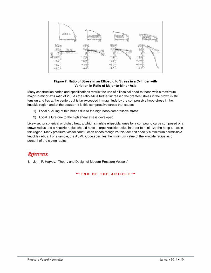
Pressure Vessel Newsletter January 2014 ♦ 10
Figure 7: Ratio of Stress in an Ellipsoid to Stress in a Cylinder with
Variation in Ratio of Major-to-Minor Axis
Many construction codes and specifications restrict the use of ellipsoidal head to those with a maximum
major-to-minor axis ratio of 2.0. As the ratio a/b is further increased the greatest stress in the crown is still
tension and lies at the center, but is far exceeded in magnitude by the compressive hoop stress in the
knuckle region and at the equator. It is this compressive stress that cause:
1) Local buckling of thin heads due to the high hoop compressive stress
2) Local failure due to the high shear stress developed
Likewise, torispherical or dished heads, which simulate ellipsoidal ones by a compound curve composed of a
crown radius and a knuckle radius should have a large knuckle radius in order to minimize the hoop stress in
this region. Many pressure vessel construction codes recognize this fact and specify a minimum permissible
knuckle radius. For example, the ASME Code specifies the minimum value of the knuckle radius as 6
percent of the crown radius.
RRRRefereneferenefereneferences:ces:ces:ces:
1. John F. Harvey, “Theory and Design of Modern Pressure Vessels”
*** E N D O F T H E A R T I C L E ***
Pressure Vessel Newsletter January 2014 ♦ 11
DESIGN & FABRICATION OF PRESSURE VESSELS: ASME SECTION VIII, DIVISION 1
Pressure vessels, along with tanks, are the workhorses for storage and processing applications in the chemical,
petroleum, petrochemical, power, pharmaceutical, food and paper industries. ASME BPV, Section VIII, Div. 1 Code is
used as a standard for the design and fabrication of pressure vessels by most companies across the world.
We would like to announce training course for "Design and Fabrication of Pressure Vessels: ASME Section VIII, Div. 1"
on February 17-19, 2014 at a convenient central location in New Delhi. This course provides the information that will help
you understand the ASME requirements for the design and fabrication of pressure vessels. The course material follows
the contents of 2010 edition of the code, and is replete with worked examples covering important aspects of pressure
vessel construction. This hands-on learning will allow you to master in 3 days what would otherwise take up to a year or
more of on-job training. This unique training course will be given in two parts:
TRAINING ANNOUNCEMENT
Basic Training (Day 1 and 2) consisting of
• Introduction to Boiler and Pressure Vessel Code
• Materials of Construction
• Low Temperature Operation
• Joint Efficiencies
• Design of Components
• Openings and Reinforcements
• Fabrication, Inspection and Tests
• Markings and Reports
Advanced Topics (Day 3) consisting of
• Tall Towers and Pressure Vessel Supports
• Nozzle Loads
• Fatigue Analysis
• Introduction to ASME Section VIII, Division 2
The instructor, Ramesh Tiwari, is internationally recognized specialist in the area of pressure vessels, heat exchangers,
materials, and codes and standards. He holds Bachelor’s and Master’s degrees in mechanical engineering from
universities in India and United States. He is also a registered Professional Engineer in the State of Maryland in the United
States. Mr. Tiwari is a member of ASME Boiler & Pressure Vessel, Section VIII Subgroup on Heat Transfer Equipment,
and a member of ASME International Working Group on B31.1 for Power Piping in India. In this capacity, he has made
invaluable contribution in resolving technical issues in compliance with the ASME codes for Code users. Mr. Tiwari has
over 24 years of design engineering experience on a variety of projects spanning industries such as oil & gas, power,
nuclear, chemical, petrochemical, pharmaceutical, food etc. He has provided engineering advice and code interpretations
to senior management and guidance to several companies he has worked for in the US, India and Germany. He has
initiated and implemented numerous innovative ideas to improve working process and quality, and developed and
conducted training programs for peers as well as clients. Mr. Tiwari is an approved pressure vessel instructor at NTPC, a
premier thermal power generating company in India and at several other companies, both public and private.
Registration fee for the training course is as follows (inclusive of service tax):
• Basic Training (Day 1 and 2) - Rs 15,500 per participant
• Advanced Topics (Day 3) - Rs 10,500 per participant
• Combo Training (Day 1, 2 and 3) - Rs 23,500 per participant
Registration fee includes training, CoDesign handbook on design and fabrication of pressure vessels, pdf copy of the
presentation, certificate from CoDesign Engineering, and beverages and lunch on all days. It excludes travel to and from
New Delhi, accommodation, and meals and beverages other than those provided during the course. We invite you to make
nominations.
In case of any queries, including the registration process, please email at [email protected], or call at +91 98109
33550.
Pressure Vessel Newsletter January 2014 ♦ 12
ACOUSTIC EMISSION EXAMINATION OF METAL PRESSURE VESSELS
Acoustic emission (AE) is a meticulous nondestructive examination (NDE) method that exposes deficient
areas in pressure vessel integrity. It is the only NDE method capable of assessing volumetric integrity during
a vessel pressure test period. When AE is used as a primary examination method during hydrostatic testing,
it supports all other NDE methods.
The guidelines, standards, practices, glossaries, and codes for AE are available from national organizations
such as the American Society for Testing Materials (ASTM), the American Society for Nondestructive
Testing (ASNT), and the American Society of Mechanical Engineers (ASME).
In 1985, a code case was approved by Section VIII to allow the use of acoustic emission in lieu of
radiography on pulsation dampeners. Acoustic emission examinations Article 11 for fiber reinforced plastic
vessels (Section X) was issued in June 1985. In December 1988, there will be the publication of Article 12,
"Acoustic Emission Examination of Metal Pressure Vessels" (Section VIII).
Acoustic emission nondestructive methods are numbered as Examination Articles 11 & 12 in Section V of
the ASME Boiler and Pressure Vessel Code . These articles provide the method for detecting and mapping
deficiencies in vessel integrity during hydrostatic testing.
A Simple Concept
Slamming a door creates an audible burst of sound (an event). The event can be described as the rapid
release of energy from a localized area. The event caused by slamming a door produces a pressure wave
that travels through the air. This pressure wave could hit a wall and bounce around a room as an echo. The
packet will hit the eardrum of a person standing near the door. The strength of the burst of noise hitting the
ears will depend on the proximity of the person near the door. The ears allow detecting of the number of
events (number of times a door slams) and the "strength" of each event. The same event activity occurs in
solid materials, but above the range of human hearing.
Metals deform in localized areas. Examples of small deformation could be a plastic zone, or metal
embrittlement. Large visual examples of deformation can be erosion pitting and cracks. These deformations
may be generated during vessel manufacture or operation. Many "events" can be generated from each area
of metal deformation. Each one of these events creates a stress wave that travels through the metal. If there
is no metal deformation, there will be no event activity. Special sensors are needed to detect acoustic
emission events caused by metal deformation.
Acoustic emission sensors are extremely sensitive to the high frequency burst events that occur as a result
of material deformation. They react much the same way the ears do. AE sensors provide an electrical output
response proportional to the strength of each event they sense. Their output can be seen as an electrical
burst sinusoidal characteristics.
Acoustic emission sensors properly placed at interval, to cover an examination area, would sense the events
from areas deforming as a result of an applied stress (i.e., hydrostatic test). More than one sensor could be
hit by the stress wave from a single event. The order of event detection can be used to locate the area
originating the event activity.
Using the AE event location information as a map, other NDE methods can be used to further examine the
areas of vessel deformation. Acoustic emission supports other NDE methods, making their use more
efficient and cost effective.
Statistical Data
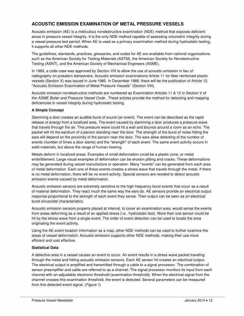
A defective area in a vessel causes an event to occur. An event results in a stress wave packet traveling
through the metal and hitting acoustic emission sensors. Each AE sensor hit creates an electrical output.
The electrical output is amplified and transmitted through a cable to a signal processor. The combination of
sensor preamplifier and cable are referred to as a channel. The signal processor monitors its input from each
channel with an adjustable electronic threshold (examination threshold). When the electrical signal from the
channel crosses this examination threshold, the event is detected. Several parameters can be measured
from this detected event signal. (Figure 1)
Pressure Vessel Newsletter January 2014 ♦ 13
Figure 1
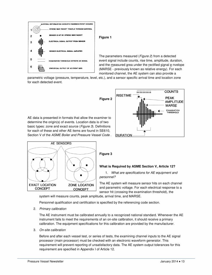
The parameters measured (Figure 2) from a detected
event signal include counts, rise time, amplitude, duration,
and the measured area under the rectified signal e nvelope
(MARSE - previously known as relative energy). For each
monitored channel, the AE system can also provide a
parametric voltage (pressure, temperature, level, etc.), and a sensor specific arrival time and location zone
for each detected event.
Figure 2
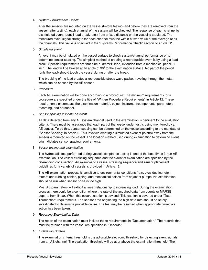
AE data is presented in formats that allow the examiner to
determine the origin(s) of events. Location data is of two
basic types: zone and exact source (Figure 3). Definitions
for each of these and other AE items are found in SE610,
Section V of the ASME Boiler and Pressure Vessel Code .
Figure 3
What is Required by ASME Section V, Article 12?
1. What are specifications for AE equipment and
personnel?
The AE system will measure sensor hits on each channel
and parametric voltage. For each electrical response to a
sensor hit (crossing the examination threshold), the
system will measure counts, peak amplitude, arrival time, and MARSE.
Personnel qualification and certification is specified by the referencing code section.
2. Primary calibration
The AE instrument must be calibrated annually to a recognized national standard. Whenever the AE
instrument fails to meet the requirements of an on-site calibration, it should receive a primary
calibration. The equipment specifications for this calibration are provided by the manufacturer.
3. On-site calibration
Before and after each vessel test, or series of tests, the examining channel inputs to the AE signal
processor (main processor) must be checked with an electronic waveform generator. This
requirement will prevent reporting of unsatisfactory data. The AE system output tolerances for this
requirement are specified in Appendix I of Article 12.
Pressure Vessel Newsletter January 2014 ♦ 14
4. System Performance Check
After the sensors are mounted on the vessel (before testing) and before they are removed from the
vessel (after testing), each channel of the system will be checked. The response of each channel to
a simulated event (pencil lead break, etc.) from a fixed distance on the vessel is tabulated. The
measured event signal strength for each channel must be within a fixed value of the average of all
the channels. This value is specified in the "Systems Performance Check" section of Article 12.
5. Simulated event
An event may be simulated on the vessel surface to check system/channel performance or to
determine sensor spacing. The simplest method of creating a reproducible event is by using a lead
break. Specific requirements are that it be a .3mm2H lead, extended from a mechanical pencil .1
inch. The lead will be broken at an angle of 30o to the examination surface. No part of the pencil
(only the lead) should touch the vessel during or after the break.
The breaking of the lead creates a reproducible stress wave packet traveling through the metal,
which can be sensed by the AE sensor.
6. Procedure
Each AE examination will be done according to a procedure. The minimum requirements for a
procedure are specified under the title of "Written Procedure Requirements" in Article 12. These
requirements encompass the examination material, object, instrument/components, parameters,
recording, and personnel.
7. Sensor spacing to locate an event
All data detected from any AE system channel used in the examination is pertinent to the evaluation
criteria. There must be assurance that each part of the vessel under test is being monitored by an
AE sensor. To do this, sensor spacing can be determined on the vessel according to the mandate of
"Sensor Spacing" in Article 2. This involves creating a simulated event at point(s) away from the
sensor(s) mounted on the vessel. The location method used during examination to determine event
origin dictates sensor spacing requirements.
8. Vessel testing and examination
The hydrostatic test performed during vessel acceptance testing is one of the best times for an AE
examination. The vessel stressing sequence and the extent of examination are specified by the
referencing code section. An example of a vessel stressing sequence and sensor placement
guidelines for a variety of vessels is provided in Article 12.
The AE examination process is sensitive to environmental conditions (rain, blow dusting, etc.),
motors and rubbing cables, piping, and mechanical noises from adjacent pumps. No examination
should be run when sensor noise is too high.
Most AE parameters will exhibit a linear relationship to increasing load. During the examination
process there could be a condition where the rate of the acquired data from counts or MARSE
departs from linear. When this occurs, caution is advised. This caution is covered under "Test
Termination" requirements. The sensor area originating the high data rate should be safely
investigated to determine probable cause. The test may be resumed when appropriate corrective
action has been taken.
9. Reporting Examination Data
The report of the examination must include those requirements in "Documentation." The records that
must be retained with the vessel are specified in "Records."
10. Evaluation Criteria
The examination criteria threshold is the adjustable electronic threshold for detecting event signals
from an AE channel. The evaluation threshold will be at or above the examination threshold. The
Pressure Vessel Newsletter January 2014 ♦ 15
value of the evaluation threshold will be specified by the referencing code section. An example of a
format for evaluation criteria is provided in Article 12.
The evaluation criteria considers two vessel conditions: one condition having seen no pressure, the
other having seen previous pressure. These considerations are important due to the fact that there
will be an absence of detectable events at a fixed examination threshold prior to reaching previously
applied pressures (Kaiser effect). The antithesis (Felicity effect) indicates a deforming area in the
vessel.
Personnel Training
Acoustic emission qualification and certification requirements are found in the 1984 edition of SNT-TC-1A.
Schools and seminars about the uses of AE technology are offered by consultants and manufacturers of AE
equipment.
Two Areas
Almost every pressure vessel can be successfully examined with AE. Evaluation criteria is needed in order
to satisfy code requirements. To begin with, two areas for AE evaluation criteria should be: (1) large vessels
requiring field erection and (2) vessels made of materials subject to weld induced cracking or embrittlement.
Final Thoughts
• Acoustic emission technology is an excellent supporting technology for other nondestructive testing
methods.
• AE is regularly used for vessel inspection by companies in the chemical and petrochemical
industries. These companies have provided the support for both ASME acoustic emission
documents.
• The Department of Transportation has acknowledged preapproved inservice examination using AE
to be superior to previously used methods of hydrostatic testing.
• The application of the technology to pressure vessels has been standardized for over 10 years by
ASTM.
• Acoustic emission applications range from continuous in-service monitoring of processes to new
product examinations lasting one second.
Author:Author:Author:Author:
Dennis A. White, President of Measurement Services International, Inc.
The above article is a part of National Board Classic Series and it was published in the National Board
BULLETIN.
*** E N D O F T H E A R T I C L E ***

Pressure Vessel Newsletter January 2014 ♦ 16
Investing In Our Common Future
CoDesign
Engineering
Training & Development
Consulting Services
It is becoming less practical for many
companies to maintain in-house
engineering staff. That is where we
come in – whenever you need us,
either for one-time projects, or for
recurring engineering services. We
understand the codes and standards
for pressure vessels, and can offer a
range of services related to them.
Pressure Vessels ● Heat Exchangers ● Piping Systems ● Welding
Oil & Gas ● Power ● Chemical ● Petrochemical ● Fertilizer ●Solar ● Biogas