Embed Size (px)
Citation preview

Pressure Gain, Stability, and Operability of Methane/Syngas Based RDEs Under Steady and
Transient ConditionsPI: Mirko Gamba
Co-I: Venkat Raman
Alex Feleo, Joshua ShepardSupraj Prakash, Caleb Van Beck
Department of Aerospace Engineering
University of Michigan
2019 UTSR Workshop, November 5 – November 7, 2019Orlando, FL
DOEDE-FE0031773 with Dr. Mark Freeman as Program Monitor

Outline
• Programmatic overview and introduction to the problem
• Experimental activities
• Computational activities
2

Outline
• Programmatic overview and introduction to the problem
• Experimental activities
• Computational activities
3

Overarching objectives
• Objective 1:Develop and demonstrate a low-loss fully axial injection concept, taking advantage of stratification effects to alter the detonation structure and position the wave favorably within the combustor
• Objective 2:Obtain stability and operability characteristics of an RDE at fixed and transient operating conditions, and determine performance rules for full-scale operations
• Objective 3:Develop quantitative metrics for performance gain, as well as quantitative description of the loss mechanisms through a combination of diagnostics development, reduced-order modeling, and detailed simulations
4

Expected outcomes: RDE physics advancements
• Outcome 1:A comprehensive study of the stability and operability of high AAR designs under engine-relevant conditions:– Air inlet design is critical to limit losses and manage secondary effects;
– Generally limits operability of devices.
• Outcome 2:A low-loss inlet design with optimal placement of detonation wave to promote efficiency gain:– Needs to be coupled to optimal design of
• Fuel/air stratification
• Detonation channel shape
• Exit nozzle shape
5

Expected outcomes: RDE methods advancements
• Outcome 3:Methods for estimating effective pressure gain realized– Basis is measurements, reduced-fidelity models, and laser diagnostics.
– A Bayesian optimization framework to combine experimental data, simulations and reduced-fidelity models to design practical RDEs
• Outcome 4:A suite of computational tools for modeling full-scale RDEs, including an AI-based acceleration for long duration simulations– Based on classification-learning approach, with automatic model reduction from
high fidelity simulation
– Implementation into U-M solvers
– Transfer of detonation computational models to industry
6
Expected outcomes: RDE technology advancement
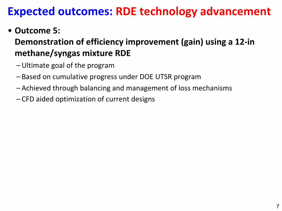
• Outcome 5:Demonstration of efficiency improvement (gain) using a 12-in methane/syngas mixture RDE– Ultimate goal of the program
– Based on cumulative progress under DOE UTSR program
– Achieved through balancing and management of loss mechanisms
– CFD aided optimization of current designs
7

ADVANCING PHYSICAL UNDERSTANDING SOURCES OF GAIN AND LOSS&
INVESTIGATING REALIAZABLE GAIN IN FIXED AND TRANSIENT CONDITIONS
Objectives and tasks
8
AIR INLET / FUEL INJECTOR DESIGN
FIXED AND TRANSIENT OPERATION & PERFORMANCE
METHODS DEVELOPMENT
B. Project organization and structure
Organizational chart
An organizational chart of the project is shown in Fig. 1. The project is organized in 4 Tasks, eachwith several subtasks, which are described in the Statement of Project Objectives (SOPO). Task1 objective is the project management and planning, while Tasks 2 through 4 are technical tasks.The work is organized following the technical tasks presented in the SOPO to readily monitortechnical progress and to ensure to successfully meeting the technical objectives.
Pressure Gain, Stability, and Operability of Methane/Syngas Based RDEs Under Steady and Transient Conditions
Objective 1Low-loss injector based RDEs for
methane/syngas operation at elevated pressure/temperature
Task 2.2Injector design for minimizing
parasitic/commensal combustion
Task 2.1Effect of stratification/fuel composition
on detonation structure
Objective 2Stability and operability characteristics
of RDEs at fixed and transient conditions
Task 3.2Stability of system to perturbations in boundary and/or operating conditions
Task 3.1Operating map of RDEs and transition between different operating conditions
Objective 3Develop tools for quantitative
diagnostics, estimation of performance, and design optimization
Task 4.2Imaging-based quantification of RDE
losses
Task 4.1Development of validated quantitative
tools for estimating pressure gain based on measurements
Task 3.3Develop design rules for operability and stability for integrated systems
Task 4.3Development of AI-based accelerated
models for long term computations
Task 2.3Develop design rules for performance
and scalability
Task 4.4Development of CFD-based design
tool using Bayesian optimization
Figure 1: Work structure for the project.
Roles and responsibilities of participants
Prof. Mirko Gamba (UM) will be the sole PI of the project. He will be responsible for the overalldirection and performance of this project. He will maintain communication with the members ofthe research team and the technical and administrative point of contact of the agency. He will beresponsible for preparing the reports, disseminating the results of the research, and maintaininginteractions with industrial and lab personnel. He will also supervise the activities to ensure thatall technical, schedule and budget objective and requirements are met. From a scientific stand-point, he will be responsible for the development and execution of the experimental activities.Gamba and his team will operate the various main experimental configurations (round and race-track RDEs), develop and apply the various diagnostics proposed in this study for the study ofgain and losses, the dynamics under fixed or transient operation, and for the design of the lowloss air inlet to be developed as part of this study. Gamba will direct graduate students who willcarry out the laboratory work. Gamba and his experimental team will contribute to tasks 2, 3 andwill develop subtasks 4.1 and 4.2.
Prof. Venkat Raman (UM) will be responsible for the computational activities. He will direct
4

Physics of RDEs and current challenges• Prior work has identified non-ideal
behaviors that alter the operation of RDEs– Secondary combustion is a dominant
phenomena, controlling the structure,dynamics and properties of the detonation;• Need and can be managed.
– Secondary waves exist, and can affect thepropagation of the primary detonation wave• Non-linear coupling with deflagration and detonation
• Need and can be managed
– Non-uniform mixing may not be a limiting factor• On the contrary, stratification can serve to stabilize wave
– Response of air inlet / fuel injector is key, but canbe managed by tuning relative responses
• Based on what learnt so far:– Develop new inlet / injector configurations that
provide strong detonation, minimizes deflagrationand secondary waves;• End goal: raise the understanding of the device and TRL
– Focus is on understanding the impact of losses on achieving gain 9
0.4
0
x/H
q/2p0 0.2
Detonation wave
Secondary waves
Secondary combustion
Injector dynamics

Outline
• Programmatic overview and introduction to the problem
• Experimental activities
• Computational activities
10

12
o Gain, where art thou?

Phenomenological model to guide design selection
16
Application of model to understanding impact of various losses and design conditions
Geometry 1 Operating condition AAssumes parameter set B
Geometry 2 Operating condition AAssumes parameter set B

Such a model can allow us to evaluate designs
17
Geometry 1
Geometry 3
Fixed operating condition
Slower wave
Faster wave
Better performance?
Worse performance?
Geometry 2

Outline
• Programmatic overview
• Experimental activities
• Computational activities
26

University of Michigan, Ann ArborDepartment of Aerospace Engineering
Venkat Raman
Future of Modeling for Gas Turbines

Progress in Modeling
2
Figure 6.16: Supersonic wrinkled flame structure.
Figure 6.17: (Left) Time-averaged isocontours of Y (OH) = 0.01 (red) and Y (H2) = 0.1(blue). (Middle) Isocontour of U = 0 (green) added. (Right) Isocontour of arbitrary pressuregradient (yellow) highlighting expansion wave front.
The e↵ect of the horseshoe on radical H spatial distribution is an important di↵erence
with the simpler ramjet-like configuration presented in Sec. 6.2. Indeed, H is created as
the cold H2 emanating from the jet recirculates upstream. Inside this pocket, H2 can partly
relax and dissociate. This permits to seed the shear layer with radical H and start up the
first chain-branching reaction earlier than in ramjet mode. A marginal concentration of H
from dissociation is enough to initiate the chain-reactions F1 and F2, which will then form
all the radicals H, O and OH needed.
6.3.2.2 Flame wrinkling and burning pockets
In Fig. 6.1, large-scale eddies form in the shear layer. Their size depends on the jet
Strouhal number [4], hence on its characteristic frequency. These eddies form flame “wrin-
226
NETL-funded Research

Is This All There is To Modeling?
• Modeling has focused on ever-increasing complexity to improve accuracy
➡ Faster computers mean more complicated models
➡ Does not necessarily decrease total compute cost
➡ May not be all that accurate either!
• Can we re-imagine modeling?
➡ What is the purpose of computational models?
➡ Do we need models only for design?
• How can models overcome time-to-solution limitation?
3

Purpose of Models
• Acceleration of modeling for gas turbine applications
• Models for real-time prediction
• Models for augmenting experiments
4

Pre-exascale Machine - SUMMIT
5
200 Pflops
GPU-Centric Design
90% of compute power on GPUs

What can SUMMIT do?
6
4000 Cores on NASA 200 GPUs on Summit 50 GPUs on SummitGPU Conversion Code Optimization
SUMMIT has 27,000 GPUS!

Distribution Statement A: Approved for Public Release; Distribution is Unlimited.
AI-based Acceleration
• Use machine learning to minimize cost of chemistry computations
7
100-1000X Speedup

AI For Improving Detonation-Driven Gas Turbine Technology
DOE Summit — 200 PetaFLOP Machine UTSR Funded Detonation Engine
• First Full Scale Simulation of RDEs with Axial Injection •Capable of simulating 100-1000 cycles in 1 day
Machine Learning Applied to Combustion Modeling (1000X Speed up Potential)
UM-GE-NETL Collaboration

Digital Twins
• Virtual machine
➡ Consists of layers of descriptors
- Descriptor enables particular input-output relation
9
PhysicalGasTurbine
ANN
ROM
SensorContent
VirtualGasTurbine
SensorData
Output
Forecast
Input

Application: Flame Transition
• Swirl-stabilized premixed combustor
• Experimental dataset:
➡ Fuel: 60% CH4 and 40% CO2.
➡ Equivalence ratio: 0.60
➡ Preheat temperature: 400 K.
➡ Air flow rate: 400 SLPM.
• Time-resolved 2D measurements
➡ OH-PLIF, PIV
➡ Total time: 1.5 sec at 10 kHz
• Objective: Predict flame transition using data
10Dataset courtesy of Q. An (U. Toronto), A. Steinberg (Ga. Tech.)
Detached Attached

Application: Flame Transition
11Dataset courtesy of Q. An (U. Toronto), A. Steinberg (Ga. Tech.)
DETAC
HED
ATTACH
ED

Probabilistic Forecasting
• Probabilistic forecasting
• Approximate transport of probability density function (PDF) of the observables
➡ Keep the forecasting affordable for real-time applications
12
t = T t = T + n
90%
10%

Clustered Reduced Order Model
13
Snapshots
Centroids
12
34
5
6
Imag
e ID
(Clu
ster
)
Time [s]Transition
Classification Time Series
Transition Matrix A
In first cluster: r0 =
100000
⎡
⎣
⎢⎢⎢⎢⎢⎢⎢
⎤
⎦
⎥⎥⎥⎥⎥⎥⎥
Transition matrix r f =
0.20.10.10.40.10.1
⎡
⎣
⎢⎢⎢⎢⎢⎢⎢
⎤
⎦
⎥⎥⎥⎥⎥⎥⎥
Snapshot at t = 0
Assign to cluster Future PDF
Prediction Step

Generating Data
• Can data be constructed by training?
14
Easy to Measure
Difficult to Measure
Only videos possible

Network architecture
15
Fully convolutional network
Downsampling phase Upsampling phaseReduces dimensionality
of PLIF imageDecodes reduced PLIF image
into PIV image
Input is PLIF field in one box
Output is PIV field in same box
Recall encoding problem:

Velocity field in time
16
PIV-x PIV-y PIV-z
Truth
Global CNN
Local CNN
m/s
m/s
m/s
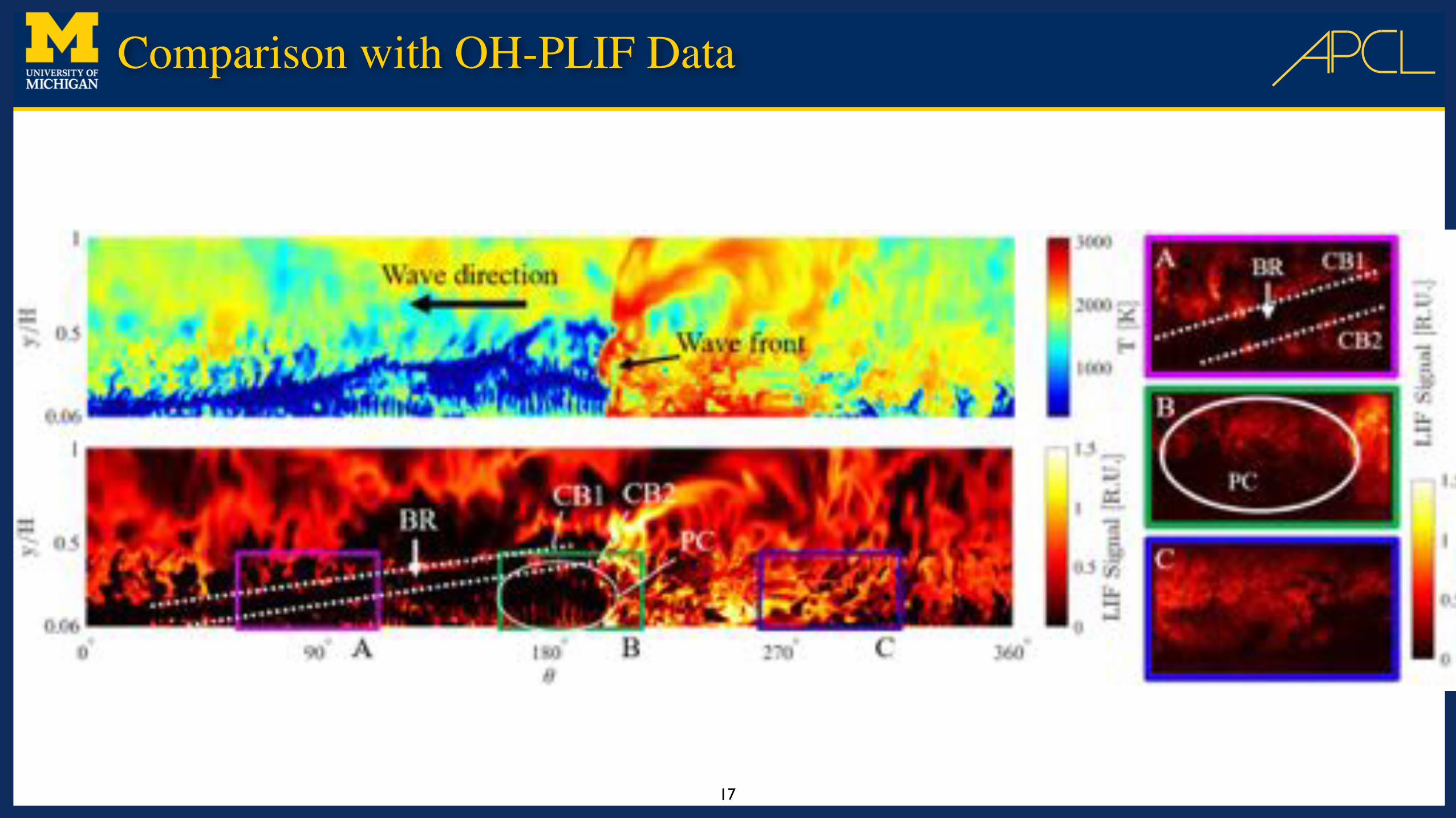
Comparison with OH-PLIF Data
17

End Goal
• We want to build J.A.R.V.I.S
18

Planned Activities
19
• AI-based simulation of RDEs
➡ 6 hour turnaround time for 100 cycles
➡ Ability to execute on in-house clusters
• Design using multi-fidelity tools
➡ Reduced-order models using high-fidelity simulations
➡ Design cycle tools for optimization
• Data assimilation from experiments
➡ Can we use canonical experiments to generate full scale experimental data?
➡ Where does this transferability come from/break?

27
Questions?


![Towards Systematic Privacy and Operability (PRIOP) Studies · Hazard and Operability Studies The international standard IEC 61882 [2] de nes what a Hazard and Operability (HAZOP)](https://img.dokumen.tips/doc/110x75/5e9fb7d8f9d766473e1e43a5/towards-systematic-privacy-and-operability-priop-studies-hazard-and-operability.jpg)