Embed Size (px)
Citation preview
Presented at 6th Pipeline Technology Conference 2011
Hannover, GermanyApril 4-5, 2011
IntroductionRecent Pipeline Leak Detection History in the US
Inspection Finding and Enforcement ActionsOverview of US Regulations & StandardsCurrent Pipeline Leak Detection Technologies
Visual Inspection/ObservationInstrumented Monitoring of Internal Pipeline System ConditionsExternal Instrumentation for Detecting Spilled Hydrocarbons
Key Considerations for Evaluating Adequacy of Pipeline Leak detection SystemsCurrent Pipeline Leak Detection Capabilities
Capabilities of Visual Leak DetectionCapabilities of Internally Instrumented Leak Monitoring SystemsCapabilities of Current External Leak Detection Technologies
Integrity Management ProgramPHMSA & Industry Research & DevelopmentIndustry ConfusionFuture & Conclusions Recommendations
Qualifications of Technical Toolboxes & strategic partner the Pipeline Research Council International (PRCI)
Presentation based on US DOT PHMSA Pipeline Leak Detection Technology Study Report to Congress as required by Section 21 of the Pipeline Inspection, Protection, Enforcement, and Safety (PIPES) Act of 2006, Public Law 109-468
Supplemented by the PRCI current 2011 pending research report & US DOT PHMSA “Advance Notice of Proposed Rulemaking (ANPRM) closed in February 2011 and formal comments/recommendations to the ANPRM by American Petroleum Institute (API) and Association of Oil Pipelines (AOPL)
The energy transportation pipeline network of the United States consists of over two million miles of pipelines.

A dependable leak detection system is important to promptly identify when a leak is occurring in order to shut down the line, isolate the leak, initiate response actions, reduce the volume of the spill, and mitigate safety, environmental, and economic consequences of the release.
This presentation describes the capabilities and limitations of leak detection systems used by operatorsof hazardous liquid pipelines as required by Section 21 of PIPES. Topics discussed include:
• The capabilities and limitations of current leak detection systems;• The results of the IM program as it relates to pipeline leak detection systems;• Inspection findings and enforcement actions;• Regulatory requirements for pipeline leak detection; and,• Advancements in leak detection technology.

Pipelines are historically a very safe means of transporting large quantities of oil, natural gas, fuels, and other hazardous materials. However, since 2002, there has been an average of two serious pipeline incidents per year and 123 significant pipeline incidents per year.
Several high-profile ruptures and explosions:Olympic, Alyeska, Colonial, El Paso, PG&E San Bruno...
By 2008 PHMSA completed inspections on all of the hazardous liquid pipeline operator's integrity programs.
In response to the leak detection issues, PHMSA has initiated enforcement actions, or formally documented its concerns, for approximately 40 percent of hazardous liquid pipeline operators to date. Slow leaks of petroleum products from aging infrastructure have also forced stricter regulations.
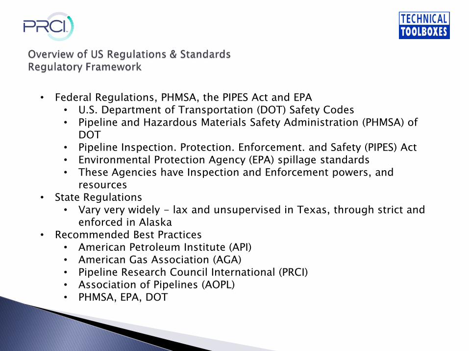
• Federal Regulations, PHMSA, the PIPES Act and EPA• U.S. Department of Transportation (DOT) Safety Codes• Pipeline and Hazardous Materials Safety Administration (PHMSA) of
DOT• Pipeline Inspection. Protection. Enforcement. and Safety (PIPES) Act• Environmental Protection Agency (EPA) spillage standards• These Agencies have Inspection and Enforcement powers, and
resources• State Regulations
• Vary very widely - lax and unsupervised in Texas, through strict and enforced in Alaska
• Recommended Best Practices• American Petroleum Institute (API) • American Gas Association (AGA)• Pipeline Research Council International (PRCI)• Association of Pipelines (AOPL)• PHMSA, EPA, DOT
Leak Detection Standards - When a CPM system is used, PHMSA requires that it conform to the requirements of the national consensus standard published by the API 1130. For Leak Detection System “Audits” API 1149 “Pipeline Variable Uncertainties and Their Effect on Leak Detection” must be followed.
Pipeline ROW Inspections - Pipeline safety regulations (CFR 192/195) require hazardous liquid pipeline operators in the United States to perform periodic visual inspections of their pipeline ROW at least 26 times per calendar year.
Corrosion Control - Regular monitoring. testing, and inspection of pipeline corrosion is required under pipeline safety regulations.
Public Awareness - Federal pipeline regulations require that pipeline operators develop and implement a public education program in accordance with API Recommended Practice 1162, which is uniqueto the characteristics and attributes of each operator's pipeline system.
Damage Prevention Program - Pipeline operators are required to have a damage prevention program to prevent pipeline damage caused by excavation activities.
Procedures/or Investigating Abnormal Operating Conditions - Federal pipeline regulations require that operators have procedures to investigate abnormal conditions.
Most hazardous liquid operators have some form of instrumented leak detection capability in place. However, PHMSA inspections identified a number of issues related to the operator's evaluation of its leak detection capabilities. Most issues fall into one of the following two categories:
• The operator's IM procedures did not adequately require or specify that a leak detection evaluation be conducted.• The operator's IM procedures required that a leak detection evaluation be conducted, but the procedure or process by which the evaluation would be conducted was inadequate in some respect.
In response to the enforcement actions, operators are required to submit revised procedures to correct inadequacies related to leak detection evaluations. Operators must then evaluate (or reevaluate) their leak detection capabilities in accordance with these corrected procedures. Before a case is closed, PHMSA reviews the revised procedures, and determines that the revisions satisfactorily address identified issues.
The methods used for leak detection cover a wide spectrum of technologies and are based on a number of different detection principles. They vary from intermittent aerial inspections to hydrocarbon sensors to Supervisory Control and Data Acquisition (SCADA) based, real-time monitoring. Each approach has its strengths and weaknesses. The operational principle, data and equipment requirements, strengths, weaknesses, and the realistic performance limits (size, response time, location, false alarm, etc.) for the leak detection methods listed above are addressed in this presentation.
Leak detection systems are varied and uniquely designed for each pipeline application. However, for discussion purposes, leak detection technologies can be classified according to the physical principles involved in the leak detection. Using this type of classification, general categories of leak detection technologies can be divided into the following three groups: visual inspection/observation, instrumented monitoring of internal pipeline system conditions, and external instrumentation for detecting spilled hydrocarbons.
Simple visual observation is reliable and is part of every pipeline ROW patrolling and monitoring program, as mandated by Federal regulations. However, it cannot assure timely detection of leaks.
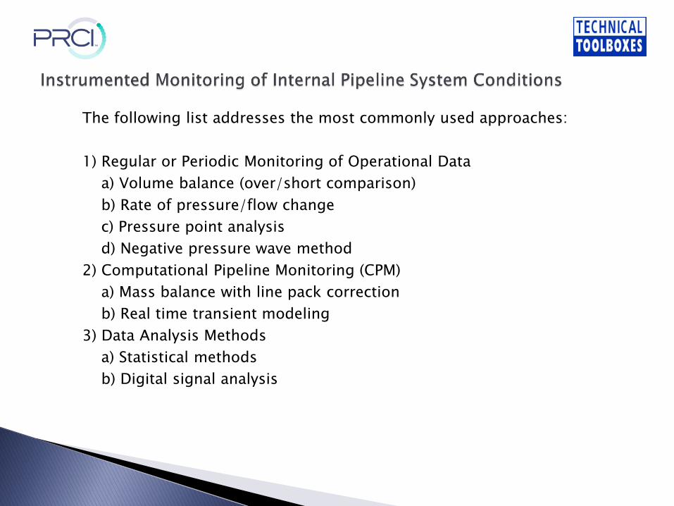
The following list addresses the most commonly used approaches:
1) Regular or Periodic Monitoring of Operational Dataa) Volume balance (over/short comparison)b) Rate of pressure/flow changec) Pressure point analysisd) Negative pressure wave method
2) Computational Pipeline Monitoring (CPM)a) Mass balance with line pack correctionb) Real time transient modeling
3) Data Analysis Methodsa) Statistical methodsb) Digital signal analysis
The following list addresses the most commonly used approaches:
1) Regular or Periodic Monitoring of Operational Data
a) Volume balance (over/short comparison)
b) Rate of pressure/flow change
c) Pressure point analysis
d) Negative pressure wave method
2) Computational Pipeline Monitoring (CPM)
a) Mass balance with line pack correction
b) Real time transient modeling
3) Data Analysis Methods
a) Statistical methods
b) Digital signal analysis
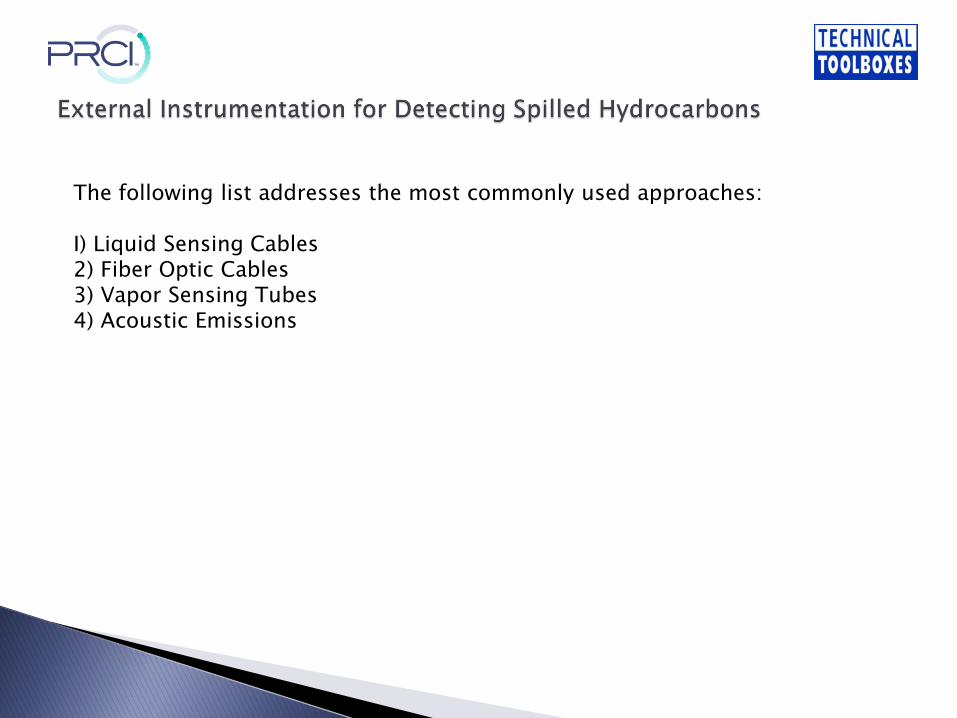
The following list addresses the most commonly used approaches:
I) Liquid Sensing Cables2) Fiber Optic Cables3) Vapor Sensing Tubes4) Acoustic Emissions
Each leak detection system is unique based on the pipeline on which it is used. As such, the capabilities of the system and the degree to which it mitigates risk must be evaluated for each pipeline system. Pipeline size, length, operating parameters and instrumentation design will affect the detection time. Key considerations that should be taken into account include, but are not limited to, the following: (Note that much of the following discussion includes comments on the internal instrumented leak detection method, since it is by far the most widely usedtechnology in the pipeline industry.)
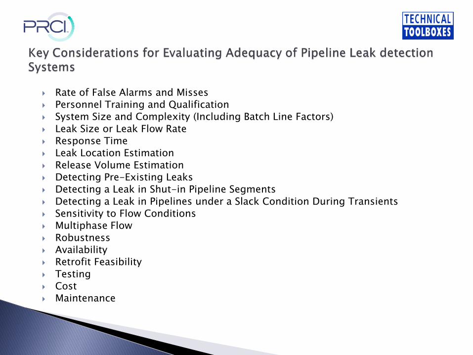
Rate of False Alarms and Misses Personnel Training and Qualification System Size and Complexity (Including Batch Line Factors) Leak Size or Leak Flow Rate Response Time Leak Location Estimation Release Volume Estimation Detecting Pre-Existing Leaks Detecting a Leak in Shut-in Pipeline Segments Detecting a Leak in Pipelines under a Slack Condition During Transients Sensitivity to Flow Conditions Multiphase Flow Robustness Availability Retrofit Feasibility Testing Cost Maintenance
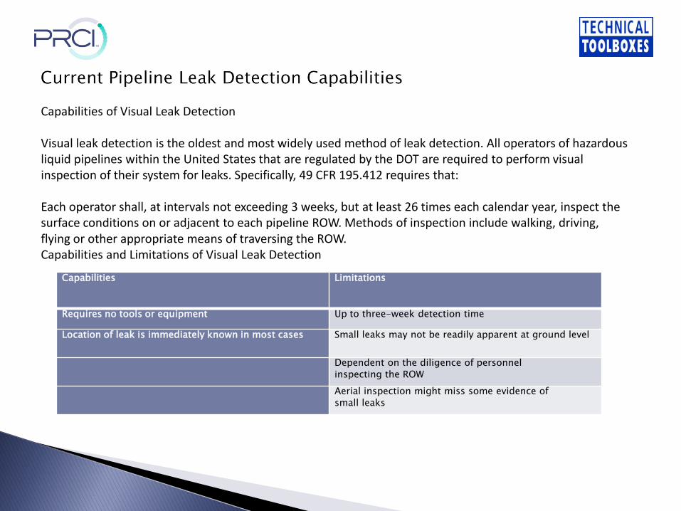
Capabilities Limitations
Requires no tools or equipment Up to three-week detection time
Location of leak is immediately known in most cases Small leaks may not be readily apparent at ground level
Dependent on the diligence of personnel
inspecting the ROW
Aerial inspection might miss some evidence of
small leaks
Capabilities of Visual Leak Detection
Visual leak detection is the oldest and most widely used method of leak detection. All operators of hazardous liquid pipelines within the United States that are regulated by the DOT are required to perform visual inspection of their system for leaks. Specifically, 49 CFR 195.412 requires that:
Each operator shall, at intervals not exceeding 3 weeks, but at least 26 times each calendar year, inspect the surface conditions on or adjacent to each pipeline ROW. Methods of inspection include walking, driving, flying or other appropriate means of traversing the ROW.Capabilities and Limitations of Visual Leak Detection

Internally based leak monitoring systems use pipeline operational data to calculate predicted operational parameters under normal conditions. The predictions are compared to measured parameters to identify differences that could indicate a leak. Geographically-distant field sensors on the pipeline are constantly polled and data is transmitted to a control center through a SCADA system. In the control center, the SCADA system then provides the needed data to a monitoring computer running the leak detection algorithm. (In some simple applications of volume balance method, the controller manually reads the instruments and performs the calculations, sometimes locally.) The quality of the data affects the system's ability to detect a leak and the pipeline size, length and operating parameters affect leak detection time.
The design, implementation, testing, and operation of these systems are addressed by API 1130.
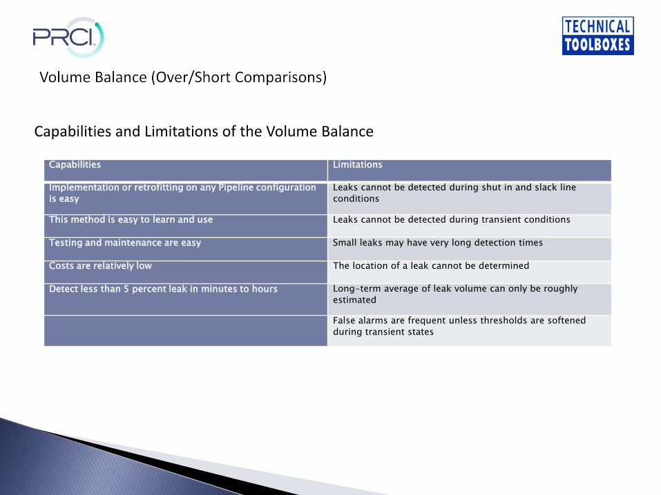
Capabilities Limitations
Implementation or retrofitting on any Pipeline configuration
is easy
Leaks cannot be detected during shut in and slack line
conditions
This method is easy to learn and use Leaks cannot be detected during transient conditions
Testing and maintenance are easy Small leaks may have very long detection times
Costs are relatively low The location of a leak cannot be determined
Detect less than 5 percent leak in minutes to hours Long-term average of leak volume can only be roughly
estimated
False alarms are frequent unless thresholds are softened
during transient states
Capabilities and Limitations of the Volume Balance

Capabilities Limitations
Leaks can be detected in shut in conditions Small leaks, existing leaks, and leaks during slack line
conditions cannot be detected
This method can estimate the volume and location of large leaks Implementation and testing are not easy
Retrofitting and maintenance are easy The method is not easy to learn and use
Able to detect 5 percent leak in minutes False alarms are frequent during transient conditions
The method is less robust
Capabilities and Limitations of the Rate of Pressure/Flow Change
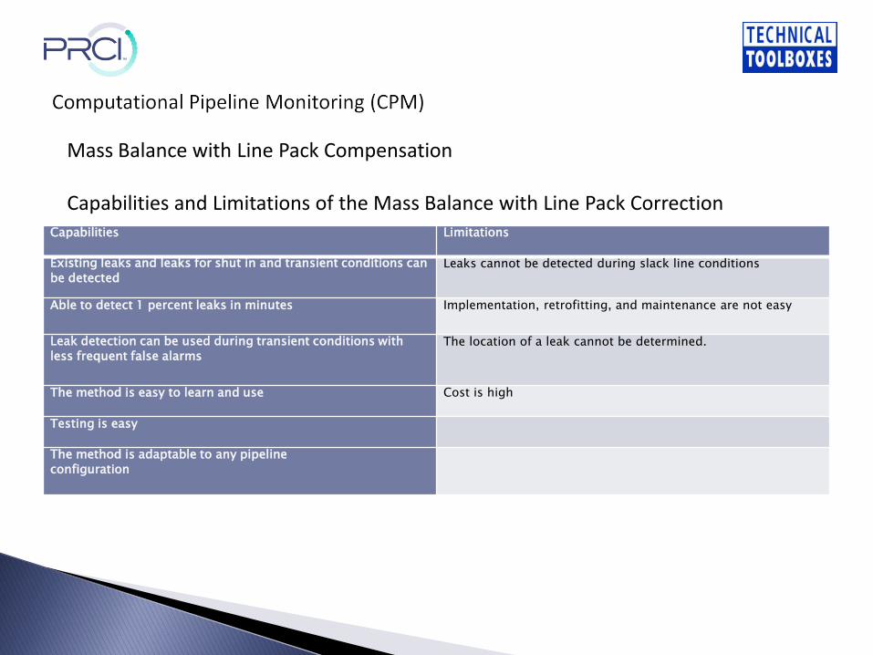
Capabilities Limitations
Existing leaks and leaks for shut in and transient conditions can
be detectedLeaks cannot be detected during slack line conditions
Able to detect 1 percent leaks in minutes Implementation, retrofitting, and maintenance are not easy
Leak detection can be used during transient conditions with
less frequent false alarmsThe location of a leak cannot be determined.
The method is easy to learn and use Cost is high
Testing is easy
The method is adaptable to any pipeline
configuration
Mass Balance with Line Pack Compensation
Capabilities and Limitations of the Mass Balance with Line Pack Correction
Capabilities Limitations
Able to detect 1 percent leaks in seconds Existing leaks cannot be detected
Leak flow rate and leak location can be estimated The method is difficult to learn and use
Leaks can be detected for shut in, slack line and transient
conditions
The model must be customized and tuned to each unique
pipeline configuration
Implementation, testing, and maintenance are difficult
Costs are very high
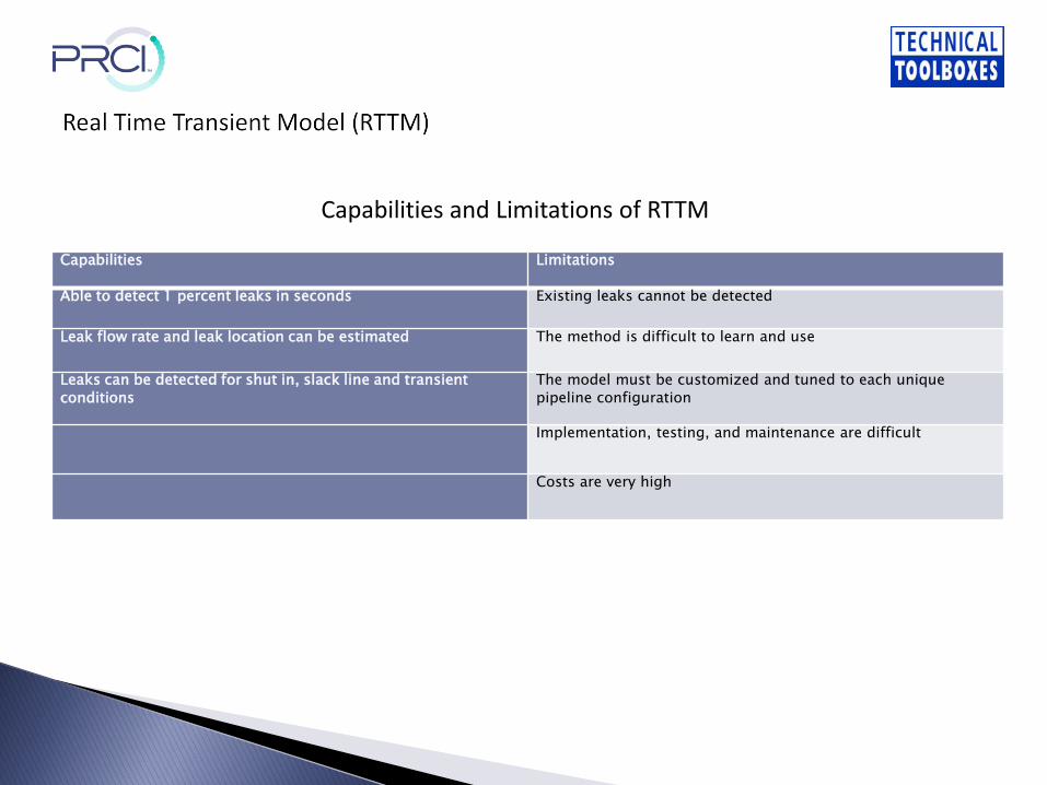
Capabilities and Limitations of RTTM
Capabilities Limitations
Able to detect 1 percent leaks in seconds to minutes Existing leaks and leaks in slack line conditions cannot be
detected
Leaks can be detected for shut in and transient conditions Leak volume difficult to estimate
False alarms are less frequent Implementation and testing are difficult
Leak location can be estimated Costs are high
Retrofitting and maintenance are easy
The method is easily adaptable to any pipeline configuration
The method is robust
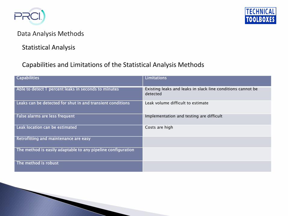
Statistical Analysis
Capabilities and Limitations of the Statistical Analysis Methods
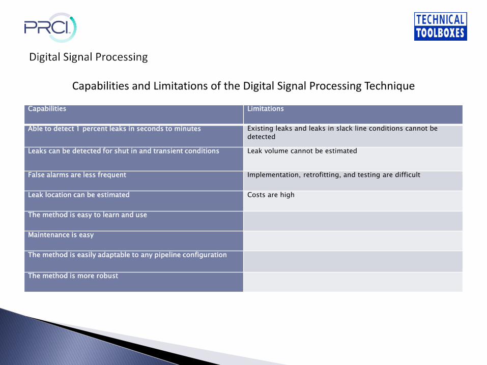
Capabilities Limitations
Able to detect 1 percent leaks in seconds to minutes Existing leaks and leaks in slack line conditions cannot be
detected
Leaks can be detected for shut in and transient conditions Leak volume cannot be estimated
False alarms are less frequent Implementation, retrofitting, and testing are difficult
Leak location can be estimated Costs are high
The method is easy to learn and use
Maintenance is easy
The method is easily adaptable to any pipeline configuration
The method is more robust
Capabilities and Limitations of the Digital Signal Processing Technique
Uniqueness of Internally Instrumented Detection MethodsThe single most important aspect of internally instrumented leak detection is each system is unique to the pipeline on which it is installed. The same system installed on two different pipelines will not have the same performance. The performance of the system is highly dependent on the pipeline on which it is installed. When evaluating the capability of a leak detection system one must consider the pipeline design and operation. Validation of leakdetection systems is best accomplished by testing the installed system. This testing should follow the requirements of API 1130.
Comparison of Internally Instrumented Leak Detection MethodsThe implementation of the various algorithms within this category varies considerably. As a result, the performance of a particular method may be significantly different from a similar system deployed on a different pipeline. Further compromising the boundary between categories are the many hybrid approaches that have been developed. For example, statistical analysis can be applied to volume balance, with pressure sensor-based line pack correction.
External leak detection methods are better suited for shorter pipeline segments due to the installation costs associated with installing either cables or vapor sensing tubes adjacent to the pipeline for the length of the pipeline to be instrumented. These types of sensors have proven results for underground storage tank applications. There are several factors that affect the performance of external leak detection systems (other than visual inspection) and should be considered as part of the selection process. A user guide developed by the Naval Facilities Engineering Service Center (UG-2028-ENV) describes selection criteria for the different methods, summarized as follows:
Soil ConditionsWater TableContinuous MonitoringSpacing of SensorsLeak Rate

Capabilities Limitations
Operated in continuous mode and may be automated Cannot estimate the size of the leak
Method can determine leak location Retrofitting to existing pipelines would be very difficult and
costly
A reasonably fast response time Multiphase flow leak may not be detected if only gas escaped
Minimally affected by multi-component flow conditions Costs are extremely high
More sensitive than computational methods and responds in
seconds to minutes
Capabilities and Limitations of Liquid Sensing Cables
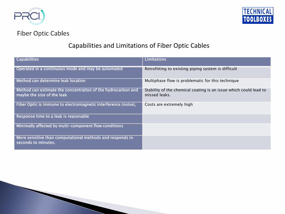
Capabilities Limitations
Operated in a continuous mode and may be automated Retrofitting to existing piping system is difficult
Method can determine leak location Multiphase flow is problematic for this technique
Method can estimate the concentration of the hydrocarbon and
maybe the size of the leak
Stability of the chemical coating is an issue which could lead to
missed leaks.
Fiber Optic is immune to electromagnetic interference (noise), Costs are extremely high
Response time to a leak is reasonable
Minimally affected by multi-component flow conditions
More sensitive than computational methods and responds in
seconds to minutes.
Capabilities and Limitations of Fiber Optic Cables

Capabilities Limitations
Operated in a continuous mode and may be automated Response time is slower than most other continuous external
measurement types.
Location of the leak can be estimated Typically used for short piping runs
The size of the leak can be estimated by concentration
measurementsThis method is not effective for above ground pipelines.
Minimally affected by multi-component or multiphase flow
conditions.Costs are extremely high
More sensitive than computational methods and responds in
minutes
Capabilities and Limitations of Vapor Sensing

Capabilities Limitations
Operated in a continuous mode and may be automated High flow noise conditions may mask the leak signal (valve or
pump noise, multiphase flow).
Method can determine the location of the leak Numerous sensors may be needed to monitor long pipelines.
Size of leak can be estimated Costs are extremely high
Minimally affected by multi-component flow
The acoustic emission method can be used on new or
retrofitted to existing pipelines.
More sensitive than computational methods and responds in
essentially real-time.
Capabilities and Limitations of Acoustic Emissions
Operators are required, by the 1M rule, to have a means to detect leaks. Operators must also perform a critical,investigative, risk-based evaluation of their leak detection capabilities. The operator's evaluation of its leak detection capabilities must consider, at a minimum, the following factors:
1. Length and size of the pipeline:2. Type of product carried:3. The pipeline's proximity to the high consequence area:4. The swiftness of leak detection:5. Location of nearest response personnel:6. Leak history; and,7. Risk assessment results.
While the IM rule focuses on additional protections for HCAs, operators also have an obligation to detect and respond to leaks in non-HCAs. Typically, the same leak detection systems and procedures are used to detect leaks on both HCAs and non-HCAs on the same pipeline.

• There are at least 80 External LDS vendors (DTS and Acoustic) in the US• There are at least 18 Computational Pipeline Monitoring (CPM) LDS vendors in
the US• There is a very real, and self-confessed, lack of know-how on LDS at the
pipeline operators• PHMSA: Operators' choices about methods of leak detection will be as varied
as the types of pipeline construction, operation, and the environments in which they operate.
• PHMSA will soon propose additional measures designed to enhance the ability of control rooms and controllers to effectively detect and mitigate the consequences of a leak.
• A key component of the IM rule is continual improvement. Each operator's IM program is expected to mature and improve over time.
• LDS should always be selected to be fit-for-purpose. A major component of its cost is continuing training, maintenance, testing and improvement over time.
• Dual or more backup systems are preferred both for redundancy (no single point of failure) and also to extend the range of effectiveness of the LDS.
• It is better to have two cheaper LDS that work in synergy, than a single expensive, badly maintained LDS
• Detailed engineering design of any LDS is needed to cover:• Suitability, sensitivity and requirements of CPM (API RP 1130 for CPM
for liquids)• Selection of instrumentation LDS (API 1149 for variable uncertainties
and their effects on LDS)• External Leak Detection Technology selection (Naval Facilities
Engineering Service Center, UG-2028-ENV)

Pipeline owner/operators should conduct a comprehensive audit and leak detection system assessment at least once every 2 years
• The audit and system assessment should consider additions and/or modifications to the pipeline network as these changes can severely impact system performance.
• The audit and system assessment should include a review of new technologies that could be used to enhance performance.
• The audit and system assessment should include a comprehensive cost/benefit analysis

For more information contact:
Joseph Summa
President & CEO
Technical Toolboxes, Inc.
(Strategic Partner of the Pipeline Research Council International)
3801 Kirby Drive, Suite 520
Houston, Texas 77098 USA
E-Mail: [email protected]
Cell: 713-828-1318
Office: 713-630-0505 Ext 203
Fax: 713-630-0560