Embed Size (px)
Citation preview

Michelangelo Ed. 02 - 2016
KIASMA® Group
1. Dredging
2. Sinking line ( sea – ports ) for dredging pressure
3. Sewage of the treatment plan (sea)
Dewatering water (shore)
4. Fall pipe for vessels
5. Electric dams
HDPE PIPES
High Pressure – Big Diameters


HDPE PIPE
HIGH PRESSURE
BIG DIAMETERS FOR DREDGING
DREDGING
KIASMA® Group
DREDGING
INTRODUCTION
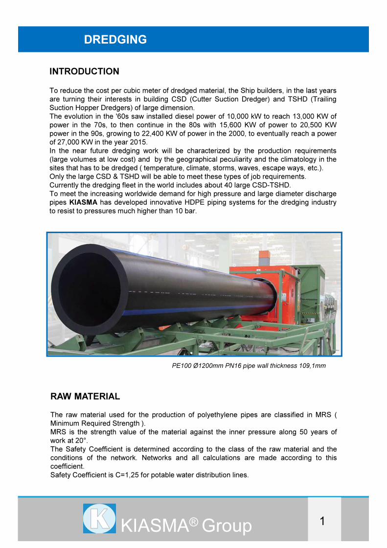
To reduce the cost per cubic meter of dredged material, the Ship builders, in the last years
are turning their interests in building CSD (Cutter Suction Dredger) and TSHD (Trailing
Suction Hopper Dredgers) of large dimension.
The evolution in the '60s saw installed diesel power of 10,000 kW to reach 13,000 KW of
power in the 70s, to then continue in the 80s with 15,600 KW of power to 20,500 KW
power in the 90s, growing to 22,400 KW of power in the 2000, to eventually reach a power
of 27,000 KW in the year 2015.
In the near future dredging work will be characterized by the production requirements
(large volumes at low cost) and by the geographical peculiarity and the climatology in the
sites that has to be dredged ( temperature, climate, storms, waves, escape ways, etc.).
Only the large CSD & TSHD will be able to meet these types of job requirements.
Currently the dredging fleet in the world includes about 40 large CSD-TSHD.
To meet the increasing worldwide demand for high pressure and large diameter discharge
pipes KIASMA has developed innovative HDPE piping systems for the dredging industry
to resist to pressures much higher than 10 bar.
KIASMA® Group 1
RAW MATERIAL
The raw material used for the production of polyethylene pipes are classified in MRS (
Minimum Required Strength ).
MRS is the strength value of the material against the inner pressure along 50 years of
work at 20°.
The Safety Coefficient is determined according to the class of the raw material and the
conditions of the network. Networks and all calculations are made according to this
coefficient.
Safety Coefficient is C=1,25 for potable water distribution lines.
PE100 Ø1200mm PN16 pipe wall thickness 109,1mm
DREDGING
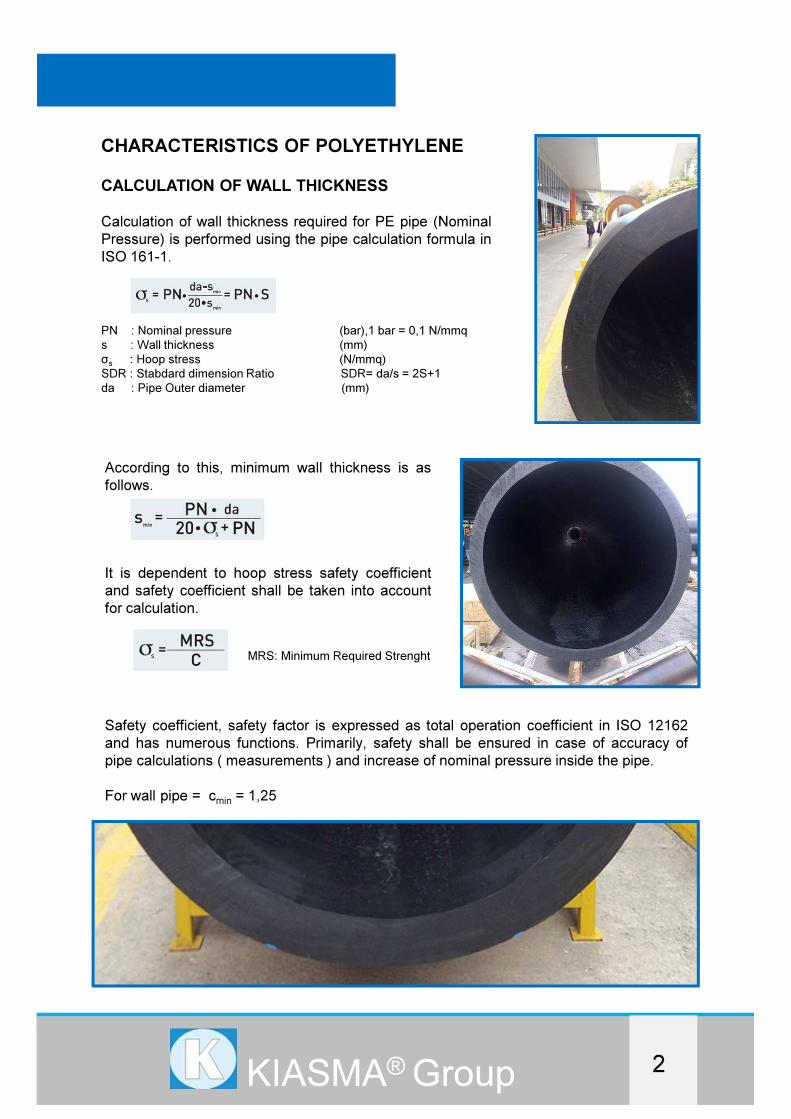
CHARACTERISTICS OF POLYETHYLENE
CALCULATION OF WALL THICKNESS
Calculation of wall thickness required for PE pipe (Nominal
Pressure) is performed using the pipe calculation formula in
ISO 161-1.
PN : Nominal pressure (bar),1 bar = 0,1 N/mmq
s : Wall thickness (mm)
σs
: Hoop stress (N/mmq)
SDR : Stabdard dimension Ratio SDR= da/s = 2S+1
da : Pipe Outer diameter (mm)
According to this, minimum wall thickness is as
follows.
It is dependent to hoop stress safety coefficient
and safety coefficient shall be taken into account
for calculation.
MRS: Minimum Required Strenght
KIASMA® Group 2
Safety coefficient, safety factor is expressed as total operation coefficient in ISO 12162
and has numerous functions. Primarily, safety shall be ensured in case of accuracy of
pipe calculations ( measurements ) and increase of nominal pressure inside the pipe.
For wall pipe = cmin
= 1,25
DREDGING
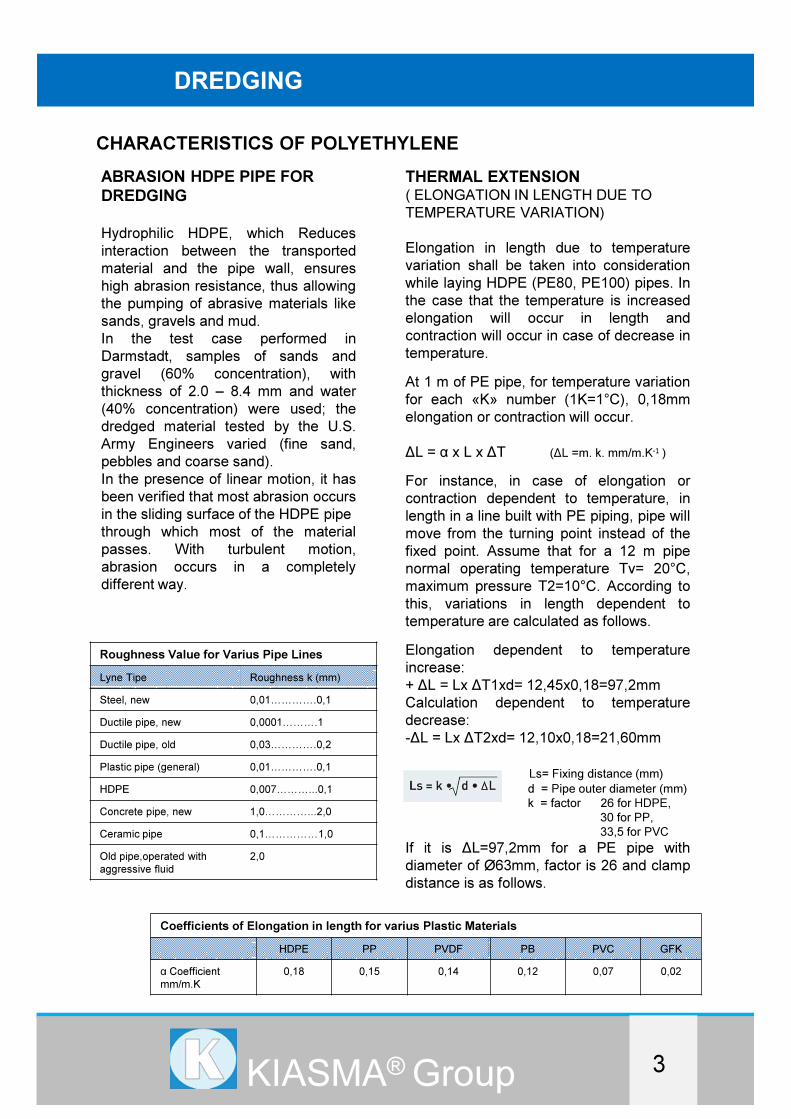
ABRASION HDPE PIPE FOR
DREDGING
Hydrophilic HDPE, which Reduces
interaction between the transported
material and the pipe wall, ensures
high abrasion resistance, thus allowing
the pumping of abrasive materials like
sands, gravels and mud.
In the test case performed in
Darmstadt, samples of sands and
gravel (60% concentration), with
thickness of 2.0 – 8.4 mm and water
(40% concentration) were used; the
dredged material tested by the U.S.
Army Engineers varied (fine sand,
pebbles and coarse sand).
In the presence of linear motion, it has
been verified that most abrasion occurs
in the sliding surface of the HDPE pipe
through which most of the material
passes. With turbulent motion,
abrasion occurs in a completely
different way.
DREDGINGDREDGING
THERMAL EXTENSION( ELONGATION IN LENGTH DUE TO
TEMPERATURE VARIATION)
Elongation in length due to temperature
variation shall be taken into consideration
while laying HDPE (PE80, PE100) pipes. In
the case that the temperature is increased
elongation will occur in length and
contraction will occur in case of decrease in
temperature.
At 1 m of PE pipe, for temperature variation
for each «K» number (1K=1°C), 0,18mm
elongation or contraction will occur.
∆L = α x L x ∆T (∆L =m. k. mm/m.K-1 )
For instance, in case of elongation or
contraction dependent to temperature, in
length in a line built with PE piping, pipe will
move from the turning point instead of the
fixed point. Assume that for a 12 m pipe
normal operating temperature Tv= 20°C,
maximum pressure T2=10°C. According to
this, variations in length dependent to
temperature are calculated as follows.
Elongation dependent to temperature
increase:
+ ∆L = Lx ∆T1xd= 12,45x0,18=97,2mm
Calculation dependent to temperature
decrease:
-∆L = Lx ∆T2xd= 12,10x0,18=21,60mm
Ls= Fixing distance (mm)
d = Pipe outer diameter (mm)
k = factor 26 for HDPE,
30 for PP,
33,5 for PVC
If it is ∆L=97,2mm for a PE pipe with
diameter of Ø63mm, factor is 26 and clamp
distance is as follows.
3KIASMA® Group
Roughness Value for Varius Pipe Lines
Lyne Tipe Roughness k (mm)
Steel, new 0,01����.0,1
Ductile pipe, new 0,0001���.1
Ductile pipe, old 0,03����.0,2
Plastic pipe (general) 0,01����.0,1
HDPE 0,007���...0,1
Concrete pipe, new 1,0����...2,0
Ceramic pipe 0,1�����1,0
Old pipe,operated with
aggressive fluid
2,0
CHARACTERISTICS OF POLYETHYLENE
Coefficients of Elongation in length for varius Plastic Materials
HDPE PP PVDF PB PVC GFK
α Coefficient
mm/m.K
0,18 0,15 0,14 0,12 0,07 0,02
DREDGING
WATER HAMMER
Water hammer occurs when valve or
pump is turned on/off. For this following
formula is used theoretically.
a : propagation speed of pressure ware (m/sec)
V : flow speed of the fluid (m/sec)
ρ : fluid density (Kg/mc)
In practice Ps value can be negative or
positive:
Positive: taps can occur when turning off
the pump or while turning it on;
Negative: when turning off the pump or in
presence of a sudden change of
hydraulic property ( ex. sudden reduction
of flow speed )
Propagation speed of pressure wave is
calculated according to the following
formula:
Short term elasticity module shall be used in this
formula(Er=800_1200N/mm2)
Short term pressure changes and water
hammer effect does not cause damage in
HDPE pipes. Following example table
indicates the rate of increase of new
pressure value which is generated by
short term water hammer under 20°C
temperature for the varius safety factor
according to the nominal pressure.
Pressure increase occurring within
values does not damage the pipe.
DREDGINGDREDGING
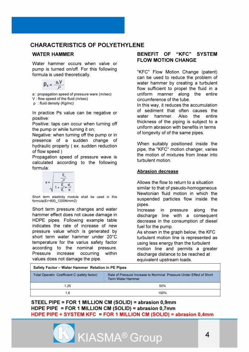
BENEFIT OF “KFC” SYSTEM
FLOW MOTION CHANGE
"KFC" Flow Motion Change (patent)
can be used to reduce the problem of
water hammer by creating a turbulent
flow sufficient to propel the fluid in a
uniform manner along the entire
circumference of the tube.
In this way, it reduces the accumulation
of sediment that often causes the
water hammer. Also the entire
thickness of the piping is subject to a
uniform abrasion with benefits in terms
of longevity of of the same pipes.
When suitably positioned inside the
pipe, the "KFC" motion changer, varies
the motion of mixtures from linear into
turbulent motion.
Abrasion decrease
Allows the flow to return to a situation
similar to that of pseudo-homogeneous
Newtonian fluid motion in which the
suspended particles flow inside the
pipes.
Increase in pressure along the
discharge line with a consequent
decrease in the consumption of diesel
fuel for the pump.
As shown in the graph below, the KFC
turbulent motion line is represented as
using less energy than the turbulent
motion line and permits a greater
discharge distance to be reached at
equivalent upstream loads.
4KIASMA® Group
Safety Factor – Water Hammer Relation in PE Pipes
Total Operatin Coefficient C (safety factor) Rate of Pressure Increase to Norminal Pressure Under Effect of Short
Term Water Hammer
1,25 50%
1,6 100%
STEEL PIPE = FOR 1 MILLION CM (SOLID) = abrasion 0,9mm
HDPE PIPE = FOR 1 MILLION CM (SOLID) = abrasion 0,7mm
HDPE PIPE + SYSTEM KFC = FOR 1 MILLION CM (SOLID) = abrasion 0,4mm
CHARACTERISTICS OF POLYETHYLENE
DREDGINGDREDGINGDREDGING
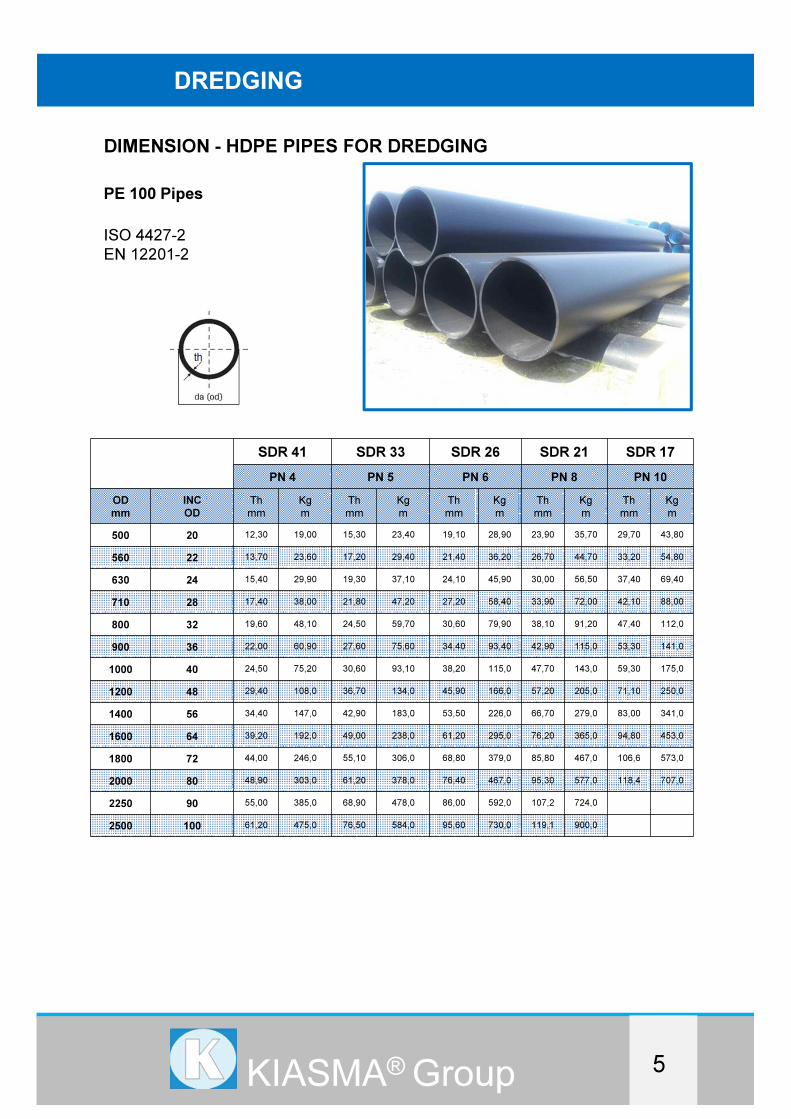
DIMENSION - HDPE PIPES FOR DREDGING
5KIASMA® Group
PE 100 Pipes
ISO 4427-2
EN 12201-2
SDR 41 SDR 33 SDR 26 SDR 21 SDR 17
PN 4 PN 5 PN 6 PN 8 PN 10
OD
mm
INC
OD
Th
mm
Kg
m
Th
mm
Kg
m
Th
mm
Kg
m
Th
mm
Kg
m
Th
mm
Kg
m
500 20 12,30 19,00 15,30 23,40 19,10 28,90 23,90 35,70 29,70 43,80
560 22 13,70 23,60 17,20 29,40 21,40 36,20 26,70 44,70 33,20 54,80
630 24 15,40 29,90 19,30 37,10 24,10 45,90 30,00 56,50 37,40 69,40
710 28 17,40 38,00 21,80 47,20 27,20 58,40 33,90 72,00 42,10 88,00
800 32 19,60 48,10 24,50 59,70 30,60 79,90 38,10 91,20 47,40 112,0
900 36 22,00 60,90 27,60 75,60 34,40 93,40 42,90 115,0 53,30 141,0
1000 40 24,50 75,20 30,60 93,10 38,20 115,0 47,70 143,0 59,30 175,0
1200 48 29,40 108,0 36,70 134,0 45,90 166,0 57,20 205,0 71,10 250,0
1400 56 34,40 147,0 42,90 183,0 53,50 226,0 66,70 279,0 83,00 341,0
1600 64 39,20 192,0 49,00 238,0 61,20 295,0 76,20 365,0 94,80 453,0
1800 72 44,00 246,0 55,10 306,0 68,80 379,0 85,80 467,0 106,6 573,0
2000 80 48,90 303,0 61,20 378,0 76,40 467,0 95,30 577,0 118,4 707,0
2250 90 55,00 385,0 68,90 478,0 86,00 592,0 107,2 724,0
2500 100 61,20 475,0 76,50 584,0 95,60 730,0 119,1 900,0

DREDGINGDREDGINGDREDGING
6KIASMA® Group
DIMENSION - HDPE PIPES FOR DREDGING
PE 100 Pipes
ISO 4427-2
EN 12201-2
SDR 13,6 SDR 11 SDR 9 SDR 7,4
PN 12,5 PN 16 PN 20 PN 25
OD
mm
INC
OD
Th
mm
Kg
m
Th
mm
Kg
m
Th
mm
Kg
m
Th
mm
Kg
m
500 20 36,80 53,30 45,40 64,50 55,80 77,30 68,30 91,80
560 22 41,20 66,90 50,80 80,80 62,50 97,00
630 24 46,30 84,60 57,20 102,0 70,30 125,0
710 28 52,20 107,0 64,50 130,0 79,30 160,0
800 32 58,80 136,0 72,60 166,0 89,30 202,0
900 36 66,10 173,0 81,70 210,0
1000 40 73,50 211,0 90,80 259,0
1200 48 88,20 304,0 109,1 375,0
1400 56 102,8 423,0
1600 64 117,5 552,0
1800 72
2000 80
2250 90
2500 100
DREDGINGDREDGINGDREDGING
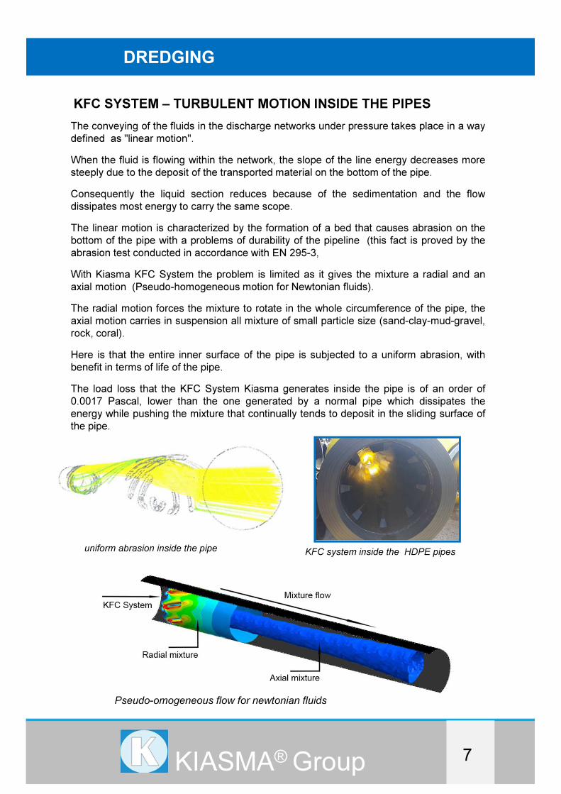
KFC SYSTEM – TURBULENT MOTION INSIDE THE PIPES
7KIASMA® Group
KFC system inside the HDPE pipes
The conveying of the fluids in the discharge networks under pressure takes place in a way
defined as "linear motion".
When the fluid is flowing within the network, the slope of the line energy decreases more
steeply due to the deposit of the transported material on the bottom of the pipe.
Consequently the liquid section reduces because of the sedimentation and the flow
dissipates most energy to carry the same scope.
The linear motion is characterized by the formation of a bed that causes abrasion on the
bottom of the pipe with a problems of durability of the pipeline (this fact is proved by the
abrasion test conducted in accordance with EN 295-3,
With Kiasma KFC System the problem is limited as it gives the mixture a radial and an
axial motion (Pseudo-homogeneous motion for Newtonian fluids).
The radial motion forces the mixture to rotate in the whole circumference of the pipe, the
axial motion carries in suspension all mixture of small particle size (sand-clay-mud-gravel,
rock, coral).
Here is that the entire inner surface of the pipe is subjected to a uniform abrasion, with
benefit in terms of life of the pipe.
The load loss that the KFC System Kiasma generates inside the pipe is of an order of
0.0017 Pascal, lower than the one generated by a normal pipe which dissipates the
energy while pushing the mixture that continually tends to deposit in the sliding surface of
the pipe.
uniform abrasion inside the pipe
Pseudo-omogeneous flow for newtonian fluids

DREDGINGDREDGINGDREDGING
8KIASMA® Group
WELDING HDPE STUB END ON THE HDPE PIPE
Big welding machine T/T for Big diameters HDPE pipes
WELDING HEAD TO HEAD STUB END /PIPE
WELDING COLLAR ELECTROFUSION STUB END /PIPE
SELF - CERTIFICATION
NORM UNI 10520:2009 – Welding Head To Head
The norm is applied for the welding process done by contact, related to thermal elements
for the realization of junctures head-head of pipe and/or polyethylene joints needed for the
transportation under pressure of fuel gas, water and other fluids. The norm also
defines the methods for the welding preparation and execution, the essential
requirements of the equipment in use and also the various inspections that have to be
carried out in order to verify the final quality.
SELF - CERTIFICATION
NORM UNI 9737 – Operator
The welding head to head is executed by an operator in possession of a certificate of
attendance as per Norm UNI 9737
SELF - CERTIFICATION
NORM UNI 10521 –Electrofusion Collar
The norm UNI 10521 is related to the welding of plastics done by electrical fusion of pipes
and joints needed for the transport under pressure of fuel, gas and water.
Control of the weld is reposted in the form.
DREDGINGDREDGINGDREDGING
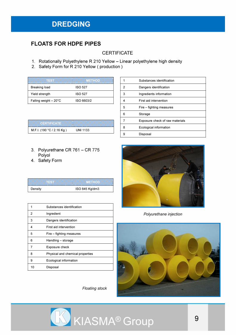
FLOATS FOR HDPE PIPES
9KIASMA® Group
1. Rotationally Polyethylene R 210 Yellow – Linear polyethylene high density
2. Safety Form for R 210 Yellow ( production )
CERTIFICATE
TEST METHOD
Breaking load ISO 527
Yield strength ISO 527
Falling weight – 20°C ISO 6603/2
CERTIFICATE
M.F.I. (190 °C / 2.16 Kg ) UNI 1133
1 Substances identification
2 Dangers identification
3 Ingredients information
4 First aid intervention
5 Fire – fighting measures
6 Storage
7 Exposure check of raw materials
8 Ecological information
9 Disposal
3. Polyurethane CR 761 – CR 775
Polyol
4. Safety Form
TEST METHOD
Density ISO 845 Kg/dm3
1 Substances identification
2 Ingredient
3 Dangers identification
4 First aid intervention
5 Fire – fighting measures
6 Handling – storage
7 Exposure check
8 Physical and chemical properties
9 Ecological information
10 Disposal
Polyurethane injection
Floating stock
DREDGINGDREDGINGDREDGING
10KIASMA® Group
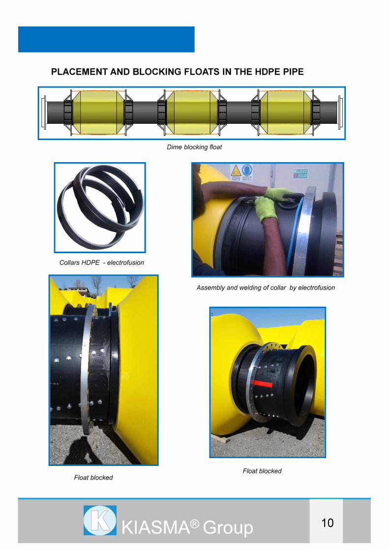
PLACEMENT AND BLOCKING FLOATS IN THE HDPE PIPE
Float blocked
Dime blocking float
Collars HDPE - electrofusion
Assembly and welding of collar by electrofusion
Float blocked

DREDGINGDREDGINGDREDGING
HDPE PIPE FOR HIGH PRESSURES
FOR DREGDING APPLICATION
11KIASMA® Group
KIASMA for the dredging sector, offers a range of discharge pipes in HDPE for pressure
up to 25 Bar ( 360 PSI), with diameters up to OD1200mm (40’’), for floating and shore
lines.
Photo from prodution
Container flat rack

HDPE PIPE HIGH PRESSURE
BIG DIAMETERS FOR DREDGING
SELF SINKING ( SEA – PORT )
KIASMA® Group

DREDGINGDREDGINGSELF SINKING ( SEA – PORT )
INTRODUCTION
12KIASMA® Group
KIASMA SRL is specialized in the marine sector of Dredging as a worldwide leader in
HDPE discharge shore and floating pipeline.
Thanks to a Joint Venture with a worldwide leader in manufacturing of HDPE with a deep
knowledge in the production of underwater pipeline, Kiasma is able to offer suitable
HDPE self sinking pipes even for dredging sector.
Kiasma R & D department knows how to work with the line and project designers.
The R & D laboratory with product tests and experts in subsea pipe laying, coordinate the
production of suitable HDPE pipes up to a diameter of 1200 mm (40 ") and working
pressure up to 25 Bar.
CHARACTERISTICS OF POLYETHYLENE : EN12201 and ISO 4427
Advantages of Polyethylene Piping
* They have high flexibility, accept bending radius down to 20 x OD .
Thus them are reliable during of installation. Elongation at break is minimum 350%.
* They are not affected from underground movements, they do not break.
* They have high resistance and crack propagation resistance.
* Since they have low interior surface roughness, they ensure significant advantages
while selecting diameter during project design.
* They are suitable for installation on sea , they are not affected from sea water and sea
movements.
* Black colored pipes are resistant to UV rays.
* They are not affected from harmful substances which are contained in the structure of
soil that cause abrasive effects. Therefore, cathode protection is not required.
* They are resistant to chemical substances.
* They do not change odor and taste of water, therefore, fit for health.
* It is not possible for plant and tree roots to penetrate inside the pipes.
* Buoyancy in sea water
* Almost unlimited lifetime underwater
* Weldable by butt fusion

DREDGINGDREDGINGDREDGING
13KIASMA® Group
INSTALLATION HDPE PIPES IN LONG LENGHTS
METHODOLOGY
Before sinking there has to be worked out a sinking procedure taking into account all
relevant conditions that can occur during installation.
A submarine pipeline is built by welding individual 11,8 m to 35,4 m lengths of pipe into a
string or "section" or by continuous extension of long lengths at the factory.
A string or section should be as long as possible, but its overall length depends on the
space available at the site. In general, lengths practically possible to handle are 500 m
depending on pipe diameter and the towing conditions (open sea, weather conditions).
The pipes should be weighted with concrete weights. The weights can be attached before
the pipe is launched into the sea, or on a barge if it is delivered in long lengths. Pipes
towed to a job site should be stored in a floating position, at a location protected from wind
and waves, and the sections should be securely anchored.
Pipeline systems are sunk in the direction from shore to the outer end.
Normally the whole pipe is sunk in one operation.
After one section is sunk, its sealed flange end rests on the sea bed. In a period with calm
weather, the pipe is filled with air to lift its end to the surface, and the sinking proceeds, as
soon as the next section in connected to the flange. During connection there must be
applied a pulling force to avoid buckling.
The sinking speed shall be checked and recorded during sinking.
A tug boat or other vessel should be available to supply the necessary pulling force.
DREDGINGDREDGINGSELF SINKING ( SEA – PORT )
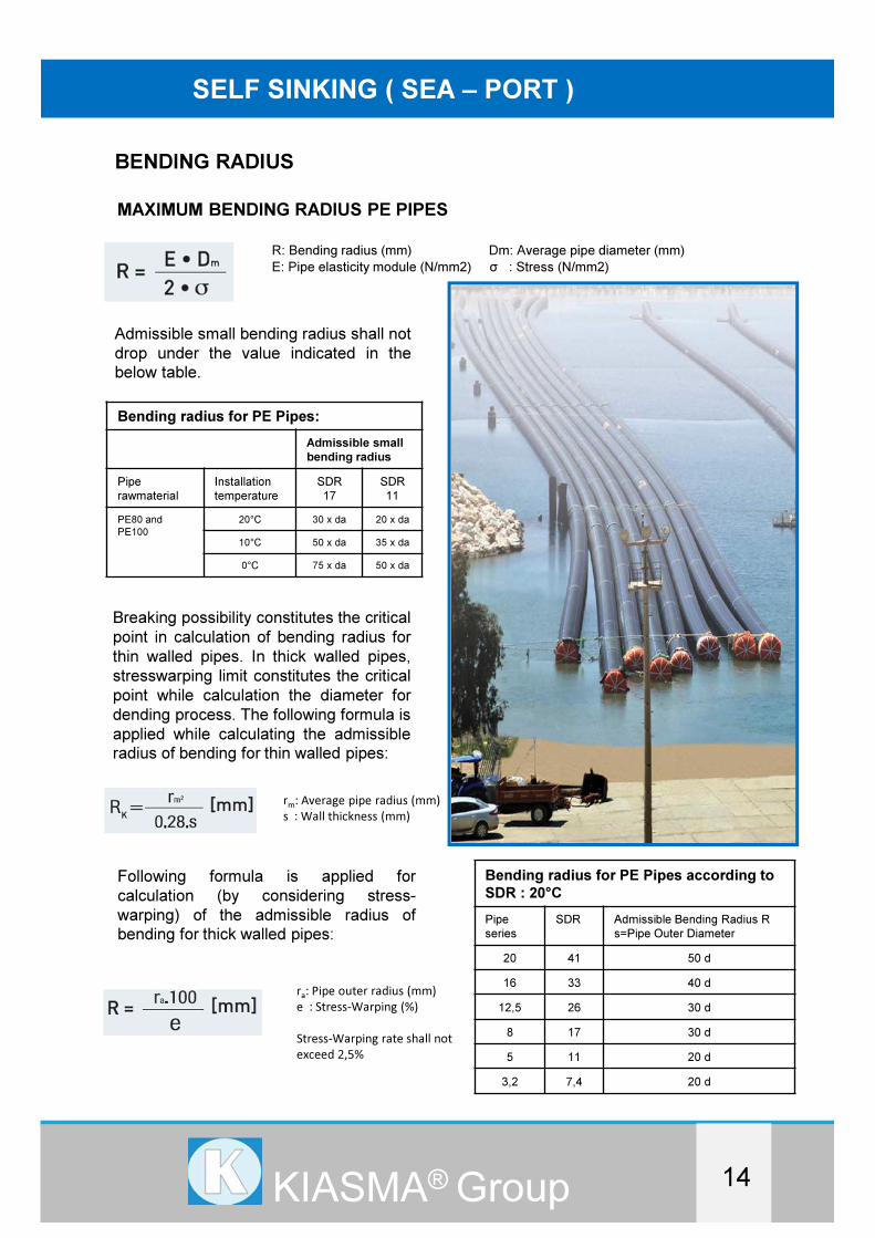
BENDING RADIUS
14KIASMA® Group
MAXIMUM BENDING RADIUS PE PIPES
R: Bending radius (mm) Dm: Average pipe diameter (mm)
E: Pipe elasticity module (N/mm2) σ : Stress (N/mm2)
Admissible small bending radius shall not
drop under the value indicated in the
below table.
Bending radius for PE Pipes:
Admissible small
bending radius
Pipe
rawmaterial
Installation
temperature
SDR
17
SDR
11
PE80 and
PE100
20°C 30 x da 20 x da
10°C 50 x da 35 x da
0°C 75 x da 50 x da
Breaking possibility constitutes the critical
point in calculation of bending radius for
thin walled pipes. In thick walled pipes,
stresswarping limit constitutes the critical
point while calculation the diameter for
dending process. The following formula is
applied while calculating the admissible
radius of bending for thin walled pipes:
rm
: Average pipe radius (mm)
s : Wall thickness (mm)
Following formula is applied for
calculation (by considering stress-
warping) of the admissible radius of
bending for thick walled pipes:
ra: Pipe outer radius (mm)
e : Stress-Warping (%)
Stress-Warping rate shall not
exceed 2,5%
Bending radius for PE Pipes according to
SDR : 20°C
Pipe
series
SDR Admissible Bending Radius R
s=Pipe Outer Diameter
20 41 50 d
16 33 40 d
12,5 26 30 d
8 17 30 d
5 11 20 d
3,2 7,4 20 d
DREDGINGDREDGINGDREDGING
15KIASMA® Group
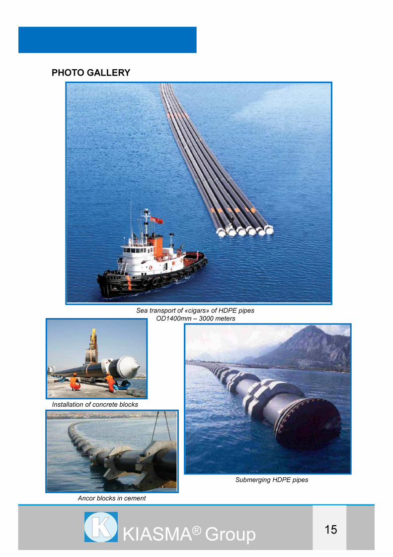
PHOTO GALLERY
Sea transport of «cigars» of HDPE pipesOD1400mm – 3000 meters
Installation of concrete blocks
Ancor blocks in cement
Submerging HDPE pipes
HDPE PIPE BIG DIAMETERS
FOR
- SELF SINKING SEWAGE OF TREATMENT PLANT (SEA)
- DEWATERING WATER (SHORE)
SEWAGE OF THE TREATMENT PLANTS
KIASMA® Group
DREDGINGDREDGINGDREDGING
16KIASMA® Group
INTRODUCTION
SEWAGE OF THE TREATMENT PLANTS
KIASMA SRL is specialized in the marine sector of Dredging as a worldwide leader in
HDPE discharge shore and floating pipeline.
Thanks to a Joint Venture with a worldwide leader in manufacturing of HDPE with a deep
knowledge in the production of underwater pipeline, Kiasma is able to offer suitable HDPE
self sinking pipes even for sewage of treatment plant (sea) and dewatering water ( shore ).
Kiasma R & D department knows how to work with the line and project designers.
The R & D laboratory with product tests and experts in subsea pipe laying and experts in
laying excavation in trenches, coordinate the production of suitable HDPE pipes up to a
diameter of ID 2500 - 2700 - 3600 mm (144 ").
HDPE PIPES APPLICATION SELF-SINKING - SEWAGE
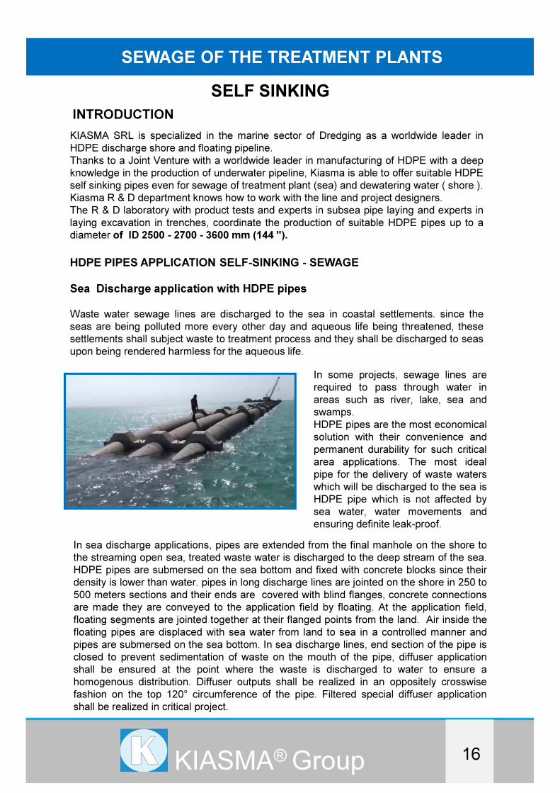
Sea Discharge application with HDPE pipes
Waste water sewage lines are discharged to the sea in coastal settlements. since the
seas are being polluted more every other day and aqueous life being threatened, these
settlements shall subject waste to treatment process and they shall be discharged to seas
upon being rendered harmless for the aqueous life.
In some projects, sewage lines are
required to pass through water in
areas such as river, lake, sea and
swamps.
HDPE pipes are the most economical
solution with their convenience and
permanent durability for such critical
area applications. The most ideal
pipe for the delivery of waste waters
which will be discharged to the sea is
HDPE pipe which is not affected by
sea water, water movements and
ensuring definite leak-proof.
In sea discharge applications, pipes are extended from the final manhole on the shore to
the streaming open sea, treated waste water is discharged to the deep stream of the sea.
HDPE pipes are submersed on the sea bottom and fixed with concrete blocks since their
density is lower than water. pipes in long discharge lines are jointed on the shore in 250 to
500 meters sections and their ends are covered with blind flanges, concrete connections
are made they are conveyed to the application field by floating. At the application field,
floating segments are jointed together at their flanged points from the land. Air inside the
floating pipes are displaced with sea water from land to sea in a controlled manner and
pipes are submersed on the sea bottom. In sea discharge lines, end section of the pipe is
closed to prevent sedimentation of waste on the mouth of the pipe, diffuser application
shall be ensured at the point where the waste is discharged to water to ensure a
homogenous distribution. Diffuser outputs shall be realized in an oppositely crosswise
fashion on the top 120° circumference of the pipe. Filtered special diffuser application
shall be realized in critical project.
SELF SINKING
DREDGINGDREDGINGDREDGING
17KIASMA® Group
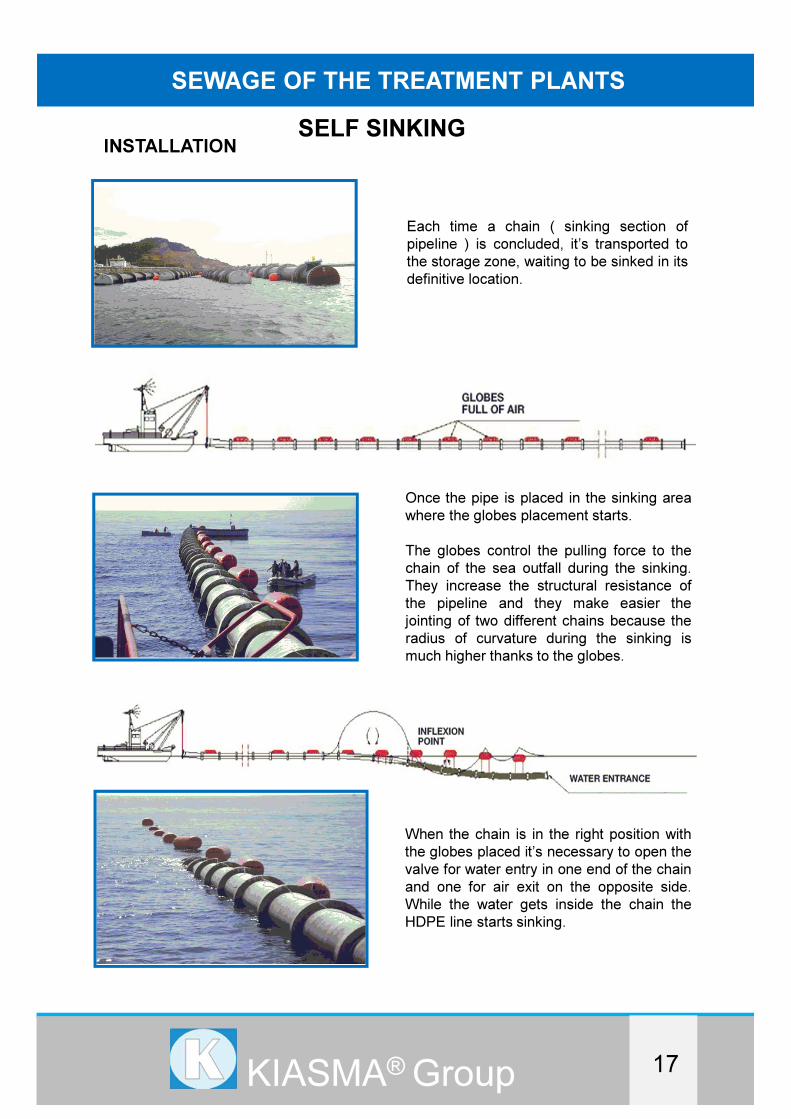
INSTALLATION
SEWAGE OF THE TREATMENT PLANTS
Each time a chain ( sinking section of
pipeline ) is concluded, it’s transported to
the storage zone, waiting to be sinked in its
definitive location.
Once the pipe is placed in the sinking area
where the globes placement starts.
The globes control the pulling force to the
chain of the sea outfall during the sinking.
They increase the structural resistance of
the pipeline and they make easier the
jointing of two different chains because the
radius of curvature during the sinking is
much higher thanks to the globes.
When the chain is in the right position with
the globes placed it’s necessary to open the
valve for water entry in one end of the chain
and one for air exit on the opposite side.
While the water gets inside the chain the
HDPE line starts sinking.
SELF SINKING

DREDGINGDREDGINGDREDGING
18KIASMA® Group
The pipeline section is sunk up to an
approximate level of – 4 meters depth and
remains in balance in that depth, full of
water and supported by the sinking globes.
In this position the provisional blind
flanges can be recovered.
Finally the air of the globes it’s taken off
following a well calculated sequence which
allow the pipeline to successfully sink up
to its definitive depth
The two pipelines come close also thanks
to the globes and the connection of two
chains starts by using pneumatic tools.
SELF SINKING

DREDGINGDREDGINGDREDGING
19KIASMA® Group
SEWAGE OF THE TREATMENT PLANTS
After the connection of two chains the
emptying of the rest of the globes starts in a
controlled way
ACCESSORIES
Concrete ballast calculated and designed in
one piece to proceed to its placement and
fixation to the pipeline
Valves of water
entry and air exit
SELF SINKING

DREDGINGDREDGINGDREDGING
20KIASMA® Group
INSTALLATION SUBMARINE TRENCHA submarine pipeline will normally be installed as a combination of trench installation and
directly laying on the seabed installation.
Whenever the water tables is higher than the center of a PE pipe, the pipe may be
subjected to buoyancy forces when it is partly filled with water.
The buoyancy forces must be overcame by the backfilling and the concrete weights.
The backfill materials on top of pipe combined with
the concrete weights provide the weight that
counterbalances the uplift due to buoyancy,
preferable with a safety factor not less than 2,0.
Note that the specific gravity of soil is diminished
when it is submerged in water.
Compaction under water is not possible.
Is required using gravel of compaction.
When in position, the pipe is filled with water and
will sink to bottom of trench. The backfilling can now
start.
If the water is deep and the trench can not be seen
from surface position, the route has to be marked
with buoys.
Trenching in soft soil under water may be done
using air or water jets to remove material, which is
then sucked up while the trench is flushed.
The trench depth depends on pipe diameter.
Sea bed material (deposits) or gravel should be
used for backfilling. After the pipe is laid, bed above
it should be restored to its original condition.
Otherwise, waves and ocean currents will erode the
changed profile. In areas where the seabed is
exposed to erosion, gabions filled with gravel should
be used for protection.
To protect the pipe, it is recommended that the top of a trench shall be covered with a
layer of concrete cast under water. The layer of concrete should be reinforced and
anchored. Otherwise the lifting forces generated by wave action might remove the
concrete.
SELF SINKING

DREDGINGDREDGINGDREDGING
21KIASMA® Group
SEWAGE OF THE TREATMENT PLANTS
WALL STRUCTURE AND EXTERIOR PROFILE TYPES HDPE PIPES
HDPE pipe ID2700mm
Wall section and technical
structure corrugate
Wall section and technical
structure single
Layer profile supported
Wall section and technical
structure double
Layer profile support
Wall section and technical
structure single
Compact layer profile
supported
Wall section and technical
structure triple
Layer profile supported
SELF SINKING

DREDGINGDREDGINGDREDGING
22KIASMA® Group
SYSTEM OF CONNECTION BETWEEN PIPES HDPE
System welding electrofusion System welding T/T fusion
System Flanged
BUOYANCY AND CONCRETE SUPPORT CALCULATION
Pipes must be anchored with concrete clamps for underwater application such as sea
discharge or extremely high groundwater for underground application in order to project
pipes from buoyancy of water.
In calculation of the assembly intervals of said concrete clamps, is should be ensured that
pipes will not be bent due to buoyancy of water.
Stability calculation for pipes:
Filled pipe calculation formula
Empty pipe calculation formula
Maximum support (concrete clamp) distance:
Fv: Lifting force (N)
da: pipe external diameter (mm)
DN: pipe internal diameter (mm)
yd: Specific density of lining (Kg/dm3)
LR: support interval (m)
LA: maximum support dis. (mm)
fLA: bending factor (0,80) (-)
Ec: Elasticity modulus (N/mm2)
JR: moment of inertia of the pipe (mm4)q: Lifting load (N/mm)
SELF SINKING
DREDGINGDREDGINGDREDGING
23KIASMA® Group
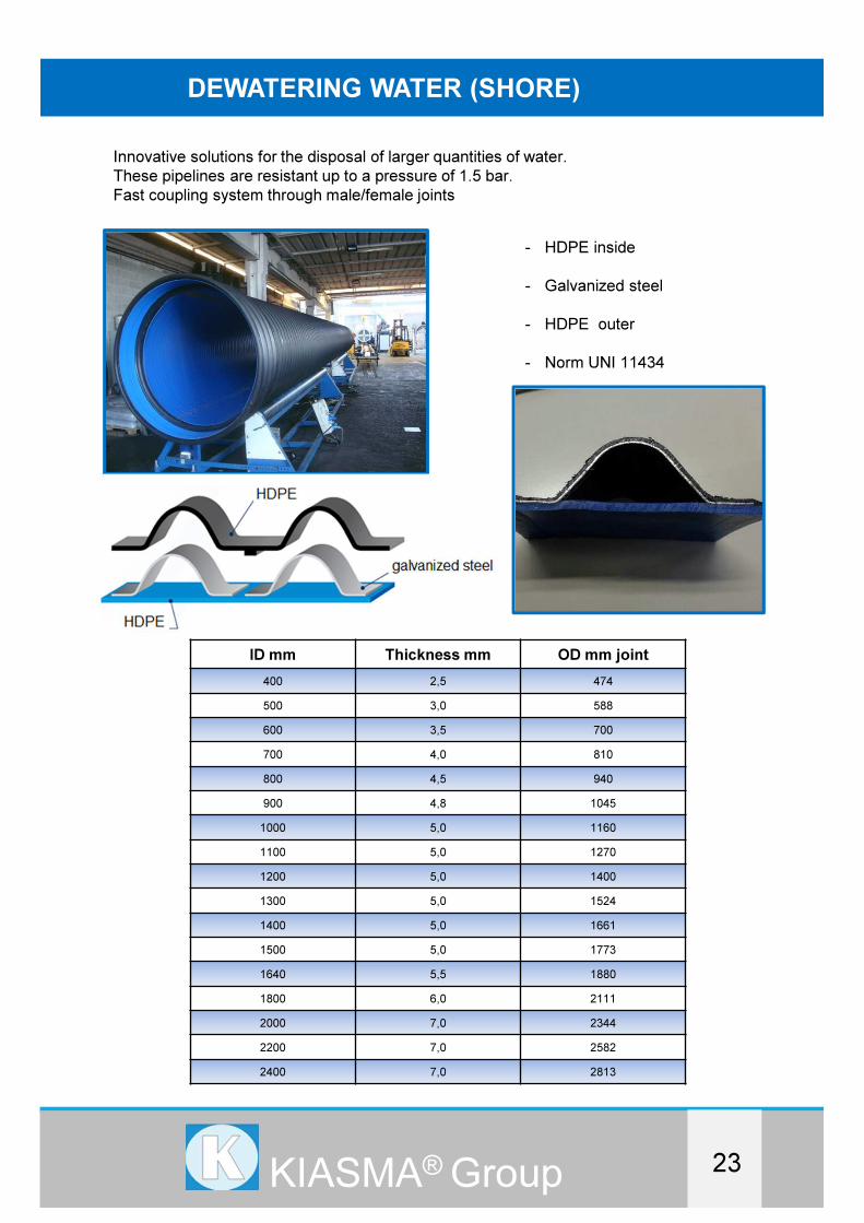
DEWATERING WATER (SHORE)
Innovative solutions for the disposal of larger quantities of water.
These pipelines are resistant up to a pressure of 1.5 bar.
Fast coupling system through male/female joints
- HDPE inside
- Galvanized steel
- HDPE outer
- Norm UNI 11434
ID mm Thickness mm OD mm joint
400 2,5 474
500 3,0 588
600 3,5 700
700 4,0 810
800 4,5 940
900 4,8 1045
1000 5,0 1160
1100 5,0 1270
1200 5,0 1400
1300 5,0 1524
1400 5,0 1661
1500 5,0 1773
1640 5,5 1880
1800 6,0 2111
2000 7,0 2344
2200 7,0 2582
2400 7,0 2813

DREDGINGDREDGINGDREDGING
24KIASMA® Group
Different types of fittings available:
For large quantities, the pipeline can be produced directly on site

DREDGINGDREDGINGDREDGING
25KIASMA® Group
The pipes are obtained thanks to a process of spiral winding of polyethylene and an omega
– shaped steel profile. Therefore, pipes consist of an inner layer in polyethylene, an outer
structured wall in polyethylene and a core of galvanized steel completely covered by a
polyethylene-based primer, which ensures a perfect blending with the two walls.
The combination of the two materials, along with the use of an omega-shaped profile,
ensures a performance that is by far better than other structured pipes in fiber glass,
concrete, cast iron or clay available on the market.
The presence of the steel has several advantages:
- higher resistance to pressure (up to 20 kN/m2), unequalled by other pipes in
thermoplastic material
- a better long-term performance, with particular reference to deformation under
constant load and a creep ratio lower than other pipes made exclusively in
polyethylene
Ring stiffness classes according to EN ISO 9969:2008:
Class A (= 8 kN/m2) corresponding to SN 8
Class B (= 12 kN/m2) corresponding to SN12
Class C (= 16 kN/m2) corresponding to SN16
DEWATERING WATER (SHORE)

DREDGINGDREDGINGDREDGING
26KIASMA® Group
CREEP test
The blend of different types of material - HDPE and steel - determines a reinforcing effect
of polymeric materials and alters the mechanical characteristics and working conditions.
Steel, in particular, reduces the CREEP effect
The pipe, therefore, in spite of its deformable structure, which means less rigid than the
surrounding soil, is extremely more resistant to ovalisation in comparison with an ordinary
structured thermoplastic pipe.
JUNCTION SYSTEM
Junction is made thanks to a male-female connection consisting of a female weld socket
and a male component equipped with an EPDM seal (complying with UNI EN 681
standard), housed in a preset slot, assuring the water-tightness of the junction system
(up to 1,2 bar pressure/0.3 bar in vacuum) according to UNI EN 1277 standard.
“Male” and “female” components feature a structured spiral wall profile, smooth inside and
corrugated outside, reinforced with an omega-like profile in galvanized steel (DX51D +
ZF/Z class) complying with UNI EN 10346 requirements and entirely embedded into the
pipe wall.
These manufacturing properties ensure a higher ring stiffness and increase product
resistance in the most critical sections of the pipeline - connections - thus reducing the
deformation of the inside diameter as much as possible.

DREDGINGDREDGINGDREDGING
27KIASMA® Group
PHYSICAL/MECHANICAL CHARACTERISTIC OF MATERIALS
The pipes combine the typical properties of polyethylene - resistance to abrasion, light
weight, minimum frictional resistance, resistance to chemical agents, versatility and ease of
installation – with the properties of steel, featuring an elastic modulus 200 times higher
than the polyethylene
ABRASION
The pipe inner surface is made of polyethylene and this ensures a high resistance to
abrasion.
As a result, pipelines may be also used for high flow speed and slope (max speed up to
10 m/s) without producing relevant abrasion effects on the inner surface.
The diagram shows how polyethylene pipes are more resistant to abrasion than other
pipes manufactured with other materials (concrete, coated concrete, fiber glass, clay, PVC
etc.)
DEWATERING WATER (SHORE)
DREDGINGDREDGINGDREDGING
28KIASMA® Group
DREDGINGDREDGINGDREDGING
29KIASMA® Group
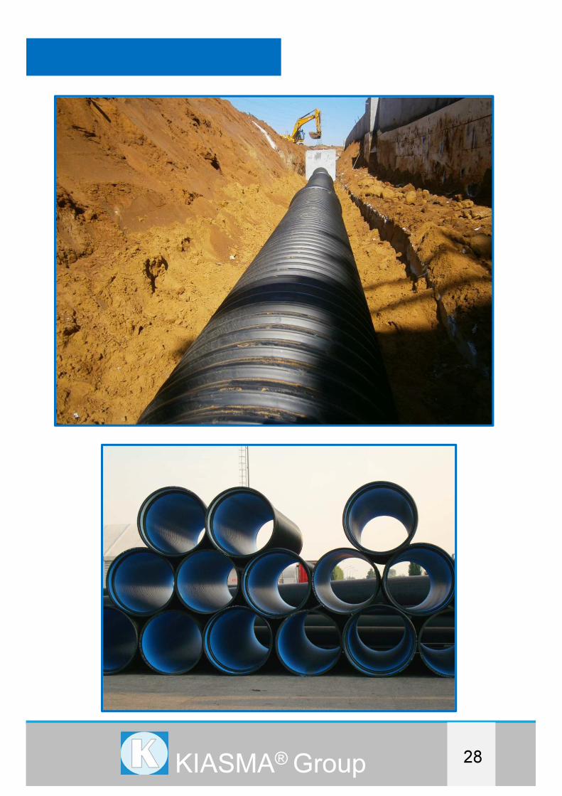
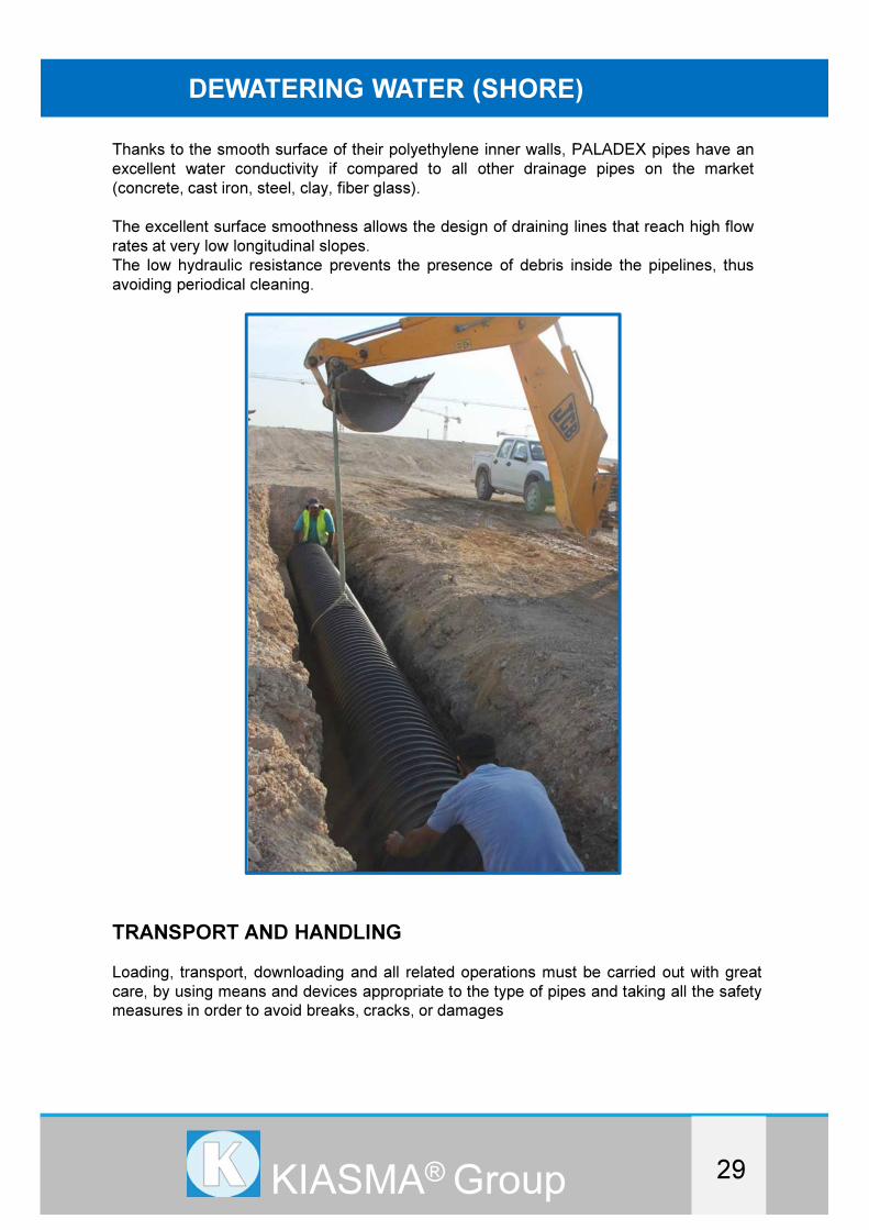
DEWATERING WATER (SHORE)
Thanks to the smooth surface of their polyethylene inner walls, PALADEX pipes have an
excellent water conductivity if compared to all other drainage pipes on the market
(concrete, cast iron, steel, clay, fiber glass).
The excellent surface smoothness allows the design of draining lines that reach high flow
rates at very low longitudinal slopes.
The low hydraulic resistance prevents the presence of debris inside the pipelines, thus
avoiding periodical cleaning.
TRANSPORT AND HANDLING
Loading, transport, downloading and all related operations must be carried out with great
care, by using means and devices appropriate to the type of pipes and taking all the safety
measures in order to avoid breaks, cracks, or damages
DREDGINGDREDGINGDREDGING
30KIASMA® Group
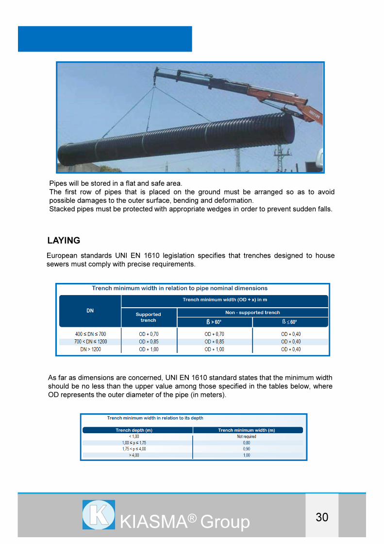
Pipes will be stored in a flat and safe area.
The first row of pipes that is placed on the ground must be arranged so as to avoid
possible damages to the outer surface, bending and deformation.
Stacked pipes must be protected with appropriate wedges in order to prevent sudden falls.
LAYING
European standards UNI EN 1610 legislation specifies that trenches designed to house
sewers must comply with precise requirements.
As far as dimensions are concerned, UNI EN 1610 standard states that the minimum width
should be no less than the upper value among those specified in the tables below, where
OD represents the outer diameter of the pipe (in meters).
DREDGINGDREDGINGDREDGING
31KIASMA® Group
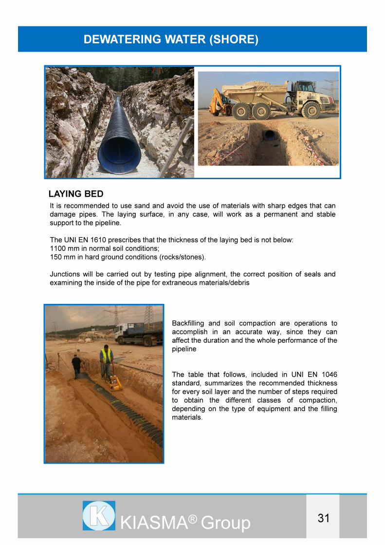
DEWATERING WATER (SHORE)
LAYING BED
It is recommended to use sand and avoid the use of materials with sharp edges that can
damage pipes. The laying surface, in any case, will work as a permanent and stable
support to the pipeline.
The UNI EN 1610 prescribes that the thickness of the laying bed is not below:
1100 mm in normal soil conditions;
150 mm in hard ground conditions (rocks/stones).
Junctions will be carried out by testing pipe alignment, the correct position of seals and
examining the inside of the pipe for extraneous materials/debris
Backfilling and soil compaction are operations to
accomplish in an accurate way, since they can
affect the duration and the whole performance of the
pipeline
The table that follows, included in UNI EN 1046
standard, summarizes the recommended thickness
for every soil layer and the number of steps required
to obtain the different classes of compaction,
depending on the type of equipment and the filling
materials.

DREDGINGDREDGINGDREDGING
32KIASMA® Group

SOLUTION A : HDPE PIPES BIG DIAMETERS
SOLUTION B : HDPE PIPES BIG DIAMETERS WITH GRP
outer layer
FALL PIPE FOR VESSELS
KIASMA® Group

DREDGINGDREDGINGDREDGING
KIASMA® Group
FALL PIPE FOR VESSELS
33

DREDGINGDREDGINGDREDGING
KIASMA® Group
DIMENSION OF HDPE PIPES
PE 100 Pipes
ISO 4427-2
EN 12201-2
SDR 41 SDR 33 SDR 26 SDR 21 SDR 17
PN 4 PN 5 PN 6 PN 8 PN 10
OD
mm
INC
OD
Th
mm
Kg
m
Th
mm
Kg
m
Th
mm
Kg
m
Th
mm
Kg
m
Th
mm
Kg
m
500 20 12,30 19,00 15,30 23,40 19,10 28,90 23,90 35,70 29,70 43,80
560 22 13,70 23,60 17,20 29,40 21,40 36,20 26,70 44,70 33,20 54,80
630 24 15,40 29,90 19,30 37,10 24,10 45,90 30,00 56,50 37,40 69,40
710 28 17,40 38,00 21,80 47,20 27,20 58,40 33,90 72,00 42,10 88,00
800 32 19,60 48,10 24,50 59,70 30,60 79,90 38,10 91,20 47,40 112,0
900 36 22,00 60,90 27,60 75,60 34,40 93,40 42,90 115,0 53,30 141,0
1000 40 24,50 75,20 30,60 93,10 38,20 115,0 47,70 143,0 59,30 175,0
1200 48 29,40 108,0 36,70 134,0 45,90 166,0 57,20 205,0 71,10 250,0
1400 56 34,40 147,0 42,90 183,0 53,50 226,0 66,70 279,0 83,00 341,0
1600 64 39,20 192,0 49,00 238,0 61,20 295,0 76,20 365,0 94,80 453,0
1800 72 44,00 246,0 55,10 306,0 68,80 379,0 85,80 467,0 106,6 573,0
2000 80 48,90 303,0 61,20 378,0 76,40 467,0 95,30 577,0 118,4 707,0
2250 90 55,00 385,0 68,90 478,0 86,00 592,0 107,2 724,0
2500 100 61,20 475,0 76,50 584,0 95,60 730,0 119,1 900,0
FALL PIPE FOR VESSELS
34

DREDGINGDREDGINGDREDGING
KIASMA® Group
DIMENSION OF HDPE PIPES
PE 100 Pipes
ISO 4427-2
EN 12201-2
SDR 13,6 SDR 11 SDR 9 SDR 7,4
PN 12,5 PN 16 PN 20 PN 25
OD
mm
INC
OD
Th
mm
Kg
m
Th
mm
Kg
m
Th
mm
Kg
m
Th
mm
Kg
m
500 20 36,80 53,30 45,40 64,50 55,80 77,30 68,30 91,80
560 22 41,20 66,90 50,80 80,80 62,50 97,00
630 24 46,30 84,60 57,20 102,0 70,30 125,0
710 28 52,20 107,0 64,50 130,0 79,30 160,0
800 32 58,80 136,0 72,60 166,0 89,30 202,0
900 36 66,10 173,0 81,70 210,0
1000 40 73,50 211,0 90,80 259,0
1200 48 88,20 304,0 109,1 375,0
1400 56 102,8 423,0
1600 64 117,5 552,0
1800 72
2000 80
2250 90
2500 100
35

DREDGINGDREDGINGDREDGING
KIASMA® Group
Solution A : HDPE pipe with steel cone
The particular nature of the material that will be discharged inside the pipes ( rock
dumping, ex rock Eclogite ) forced us to be very uncompromising with the type of polymer
that we would have to use for the production of these pipes.
Our offer proposes pipe made of virgin HDPE PE 100, EN12201 – ASTM4710 PLUS
ISO4427-2 –Type BL, very resistant to crack test which also prevents the propagation of
the fractures.
description Quantity
No.
Price EXW
euro
Amount
EXW Euro
ex:
HDPE PE100 Type BL according to EN12201
international standard
OD1200mm thickness 43,4 mm ID 1113,20
mm working pressure 6 Bar SDR26
flanged on only one side with galvanized steel
flange DN1200 PN10 UNI 1092
including:
1. Gasket
No E
PipesEuro/pipe
E..
Euro
�..
FALL PIPE FOR VESSELS
36
DREDGINGDREDGINGDREDGING
KIASMA® Group
description Quantity
No.
Price
EXW
euro
Amount
EXW Euro
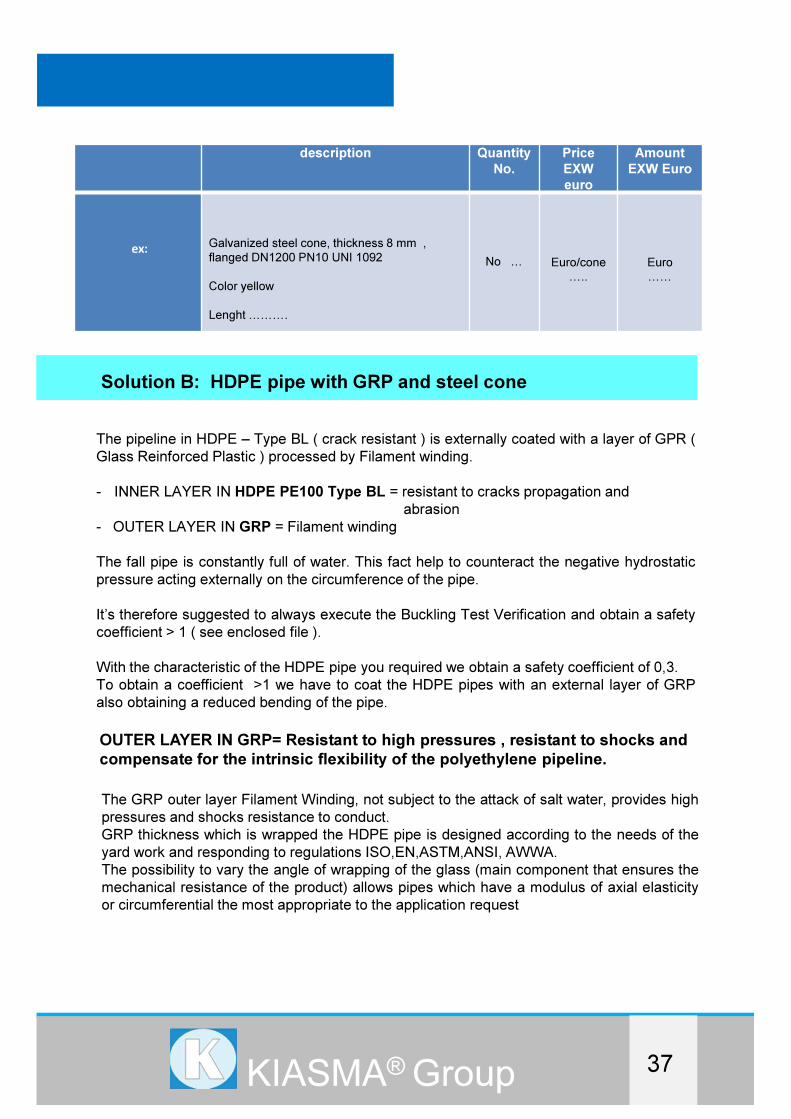
ex:Galvanized steel cone, thickness 8 mm ,
flanged DN1200 PN10 UNI 1092
Color yellow
Lenght EEE.
No E Euro/cone
E..
Euro
EE
Solution B: HDPE pipe with GRP and steel cone
The pipeline in HDPE – Type BL ( crack resistant ) is externally coated with a layer of GPR (
Glass Reinforced Plastic ) processed by Filament winding.
- INNER LAYER IN HDPE PE100 Type BL = resistant to cracks propagation and
abrasion
- OUTER LAYER IN GRP = Filament winding
The fall pipe is constantly full of water. This fact help to counteract the negative hydrostatic
pressure acting externally on the circumference of the pipe.
It’s therefore suggested to always execute the Buckling Test Verification and obtain a safety
coefficient > 1 ( see enclosed file ).
With the characteristic of the HDPE pipe you required we obtain a safety coefficient of 0,3.
To obtain a coefficient >1 we have to coat the HDPE pipes with an external layer of GRP
also obtaining a reduced bending of the pipe.
OUTER LAYER IN GRP= Resistant to high pressures , resistant to shocks and
compensate for the intrinsic flexibility of the polyethylene pipeline.
The GRP outer layer Filament Winding, not subject to the attack of salt water, provides high
pressures and shocks resistance to conduct.
GRP thickness which is wrapped the HDPE pipe is designed according to the needs of the
yard work and responding to regulations ISO,EN,ASTM,ANSI, AWWA.
The possibility to vary the angle of wrapping of the glass (main component that ensures the
mechanical resistance of the product) allows pipes which have a modulus of axial elasticity
or circumferential the most appropriate to the application request
37

DREDGINGDREDGINGDREDGING
KIASMA® Group
Average values for the principal physical-mechanical properties of laminated in Filament
Winding:
breaking load traction circumferential : 2000 ÷ 4000 Kg/cm2
breaking load axial tensile : 400 ÷ 1200 Kg/cm2
elastic modulus traction circumferential : 100000 ÷ 300000 Kg/cm2
elastic modulus axial tensile: 50000 ÷ 125000 Kg/cm2
breaking load cut : 600 Kg/cm2
breaking load of compression : 2200 Kg/cm2
specific weight: 1,9
coefficient of linear expansion: 20,10 m/m °C
resilience : 220 Kg/ cm/cm2
electrical resistivity: 10 ohm cm
thermal conductivity: 0,2 Kca l/ (m2 h °C)
Pipeline “HDPE +GRP SYSTEM”
FALL PIPE FOR VESSELS
38
DREDGINGDREDGINGDREDGING
KIASMA® Group
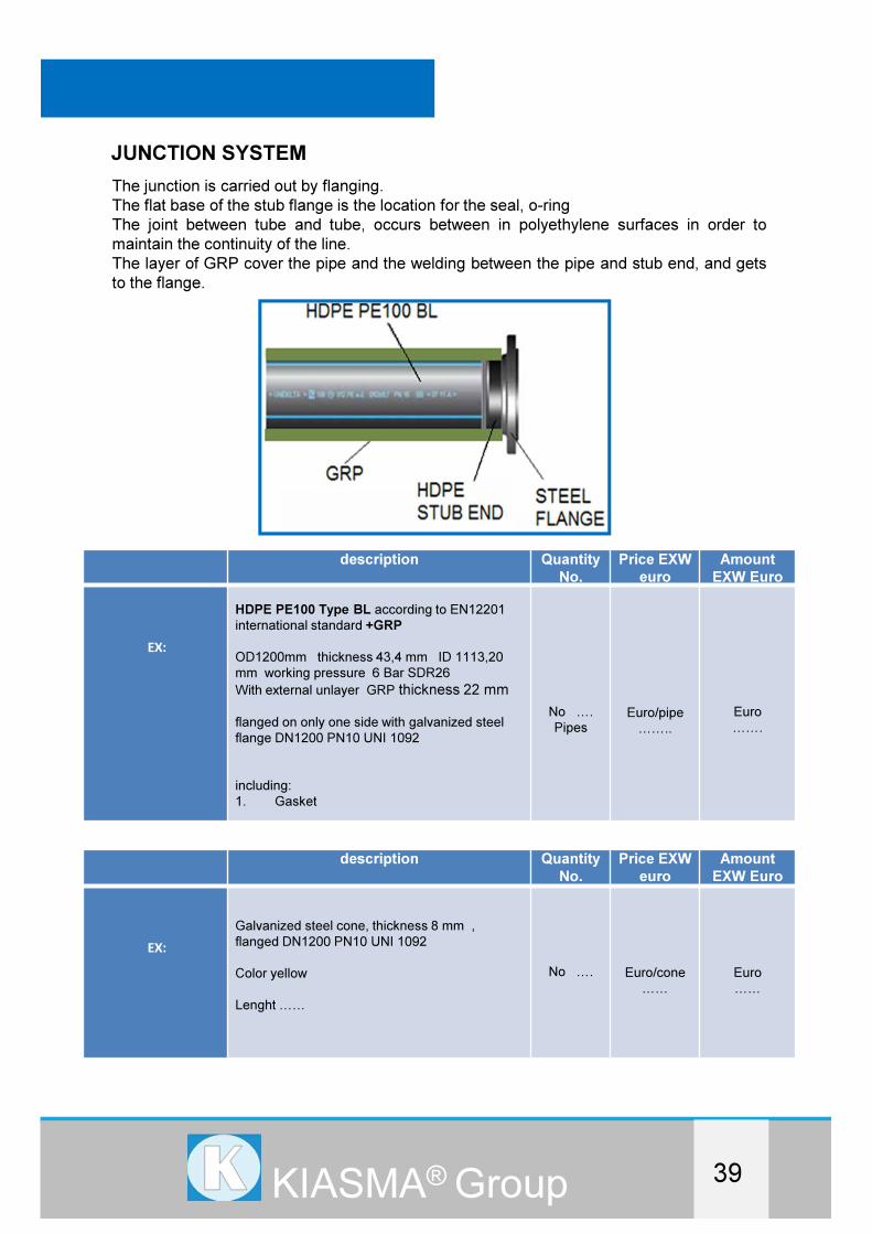
JUNCTION SYSTEM
The junction is carried out by flanging.
The flat base of the stub flange is the location for the seal, o-ring
The joint between tube and tube, occurs between in polyethylene surfaces in order to
maintain the continuity of the line.
The layer of GRP cover the pipe and the welding between the pipe and stub end, and gets
to the flange.
description Quantity
No.
Price EXW
euro
Amount
EXW Euro
EX:
HDPE PE100 Type BL according to EN12201
international standard +GRP
OD1200mm thickness 43,4 mm ID 1113,20
mm working pressure 6 Bar SDR26
With external unlayer GRP thickness 22 mm
flanged on only one side with galvanized steel
flange DN1200 PN10 UNI 1092
including:
1. Gasket
No E.
PipesEuro/pipe
EE..
Euro
EE.
description Quantity
No.
Price EXW
euro
Amount
EXW Euro
EX:
Galvanized steel cone, thickness 8 mm ,
flanged DN1200 PN10 UNI 1092
Color yellow
Lenght EE
No E. Euro/cone
EE
Euro
EE
39

DREDGINGDREDGINGDREDGING
KIASMA® Group
JOINT SYSTEM BETWEEN THE PIPES
To help the joint of the pipes they have a cone on top of them
For the joint of the pipes in HDPE + GRP system the joint is the same.
A flanged cone from one side joins the flange of the pipe and the other side is conical with an
angle dimension able to fit the upper pipe and allow the inclination of it of 15 – 20° avoiding
the upper pipe to get out of its position.
FALL PIPE FOR VESSELS
40

DREDGINGDREDGINGDREDGING
KIASMA® Group
BUCKLING TEST
41

HDPE PRESSURE PIPES
LARGE DIAMETER FOR ELECTRICAL DAMS
ELECTRIC DAMS
KIASMA® Group

DREDGINGDREDGINGDREDGING
KIASMA® Group
ELECTRIC DAMS
INTRODUCTION
KIASMA SRL is specialized in the marine sector of Dredging as a worldwide leader in
HDPE discharge shore and floating pipeline.
Thanks to a Joint Venture with a worldwide leader in manufacturing of HDPE with a deep
knowledge in the production of underwater pipeline, Kiasma is able to offer suitable HDPE
pipe for transmission lines which portable water. KIASMA R & D department knows how
to work with the line and project designers.
The R & D laboratory with product tests and experts in subsea pipe laying, coordinates the
production of suitable HDPE pipes up to a diameter of 4000 mm (160 ") and working
pressure up to 25 Bar.
The response to the growing demand of high pressure pipes for big diameters was the
development of an innovative pipe system able to resist to a working pressure up to 25
Bar with a diameters range from 800 mm to 4000 mm.
These pipes are mostly characterized by their low weight, a quick and easy installation,
besides their unique joining system, the electro fused socket.
Moreover the system provides a high resistance to chemical agents, UV, rays, rodents,
micro organisms and termites and also features good hydraulic properties.
42

DREDGINGDREDGINGDREDGING
KIASMA® Group
ELECTRIC DAMS
PIPE DIMENSION NORMS ISO/CD 29561-2 ASTM F2720
Large diameter pipe behind the dam wall
43
PN6 bar SIDR47
SN 2.0 kN/m2
PN8 bar SIDR35
SN 4.5 kN/m2
PN10 bar SDR27
SN 10 kN/m2
PN12.5 bar SDR21
SN 18 kN/m2
Nominal
inside Dia
ID(mm)
Wall thick
s(mm)
Weight
(kg/m)
Wall thick
s(mm)
Weight
(kg/m)
Wall thick
s(mm)
Weight
(kg/m)
Wall thick
s(mm)
Weight
(kg/m)
800 17,3 52,5 23,1 68,3 29,4 85,8 37,3 112,0
1000 21,7 78,8 28,9 105,0 36,7 133,0 46,6 173,3
1200 26,0 112,0 34,7 150,5 44,0 194,3 56,0 250,3
1400 30,3 150,5 40,5 206,5 51,4 264,3 65,3 341,3
1600 34,7 201,3 46,3 269,5 58,7 344,8 74,6 446,3
1800 39,0 253,8 52,1 341,3 66,1 441,0 84,0 565,3
2000 43,3 311,7 57,9 421,8 73,4 542,5 93,3 703,3
2200 47,7 375,0 63,6 514,5 80,7 656,3 102,6 850,5
2400 52,0 451,7 69,4 612,5 88,1 778,8 111,9 1012
2600 56,3 526,7 75,2 717,5 95,4 911,8 121,3 1197
2800 60,7 607,5 81,0 833,0 102,7 1055 130,6 1390
3000 65,0 700,0 86,8 955,5 110,1 1208 139,9 1607
3200 69,3 805,0 92,6 1096 117,4 1397 149,3 1829
3400 73,7 903,3 98,4 1237 124,8 1573 158,6 2065
3600 78,0 1010 104,1 1386 132,1 1759 167,9 2319
3800 82,3 1120 109,9 1545 139,4 1974 177,2 2602
4000 86,7 1253 115,7 1726 146,8 2184 186,6 2884

DREDGINGDREDGINGDREDGING
KIASMA® Group
PIPE DIMENSION NORMS ISO/CD 29561-2 ASTM F2720
Large diameter pipe that bringsWater to the turbines
44
PN16 bar SIDR17
SN 36 kN/m2
PN20 bar SIDR13
SN 73 kN/m2
PN25 bar SDR10,5
SN 137 kN/m2
Nominal
inside Dia
ID(mm)
Wall thick
s(mm)
Weight
(kg/m)
Wall thick
s(mm)
Weight
(kg/m)
Wall thick
s(mm)
Weight
(kg/m)
800 47,5 143,5 60,8 187,3 77,0 243,0
1000 59,4 224,0 76,0 294,0 96,0 382,0
1200 71,3 323,8 91,2 425,3 115,0 553,0
1400 83,2 441,0 106,4 579,3 134,0 758,0
1600 95,1 581,0 121,6 763,0 153,0 969,0
1800 107,0 736,8 136,8 974,8 172,0 1264,0
2000 118,9 917,0 152,0 1202 191,0 1566,0
2200 130,8 1110 167,2 1468
2400 142,6 1330 197,6 1899
2600 154,5 1561
2800 166,4 1829
3000 178,3 2098
3200 190,2 2394
3400
3600
3800
4000

DREDGINGDREDGINGDREDGING
KIASMA® Group
ELECTRIC DAMS
RAW MATERIAL
The Pipe is made up from of HDPE; Glass Fibre and compound materials.
The pipes inner and outer surface is made up from HDPE, while the middle layer is made
up from a composite structure.
Production of pipes
Joining with electrofusion system
Installation
Besides joining by the electrofusion
method, this pipe system can also be
joined by using normal flange connections.
This time saving joining method makes it
possible to connect several pipes
simultaneously and to install the pipes in
very narrow tranches in very short time.
This pipes don't break or crak, even under
30% deformation.
This means that, even if the pipes deform
up to 30%, the there will be no decrease in
the performance the system
45
Type A : Bayonet connection
Type B : Female ring connection
Type C : Release system to the discharge pipeline
QUICK COUPLING
KIASMA® Group

DREDGINGDREDGINGDREDGING
KIASMA® Group 46
QUICK COUPLING
Type A : Bayonet connection
Bayonet connection (6 claws)
The female part with claws will be a cast part with a 10 mm thickness
The male part is provided with a bayonet ring, which can be rotated separately.
The seal is provided by a sturdy lip seal, similar to what is used in the bayonet ball joints.
This seal has been used for over 60 years in the dredging industry and provides optimal
sealing, even in wearing and corrosive circumstances.

DREDGINGDREDGINGDREDGING
KIASMA® Group 47
Type B : Female ring connection
Two shares male flanged
A female ring connecting the two male parts
The seal is provided by a sturdy lip seal. This seal provides optimal sealing, even in
wearing and corrosive circumstances
DREDGINGDREDGINGDREDGING
KIASMA® Group 48
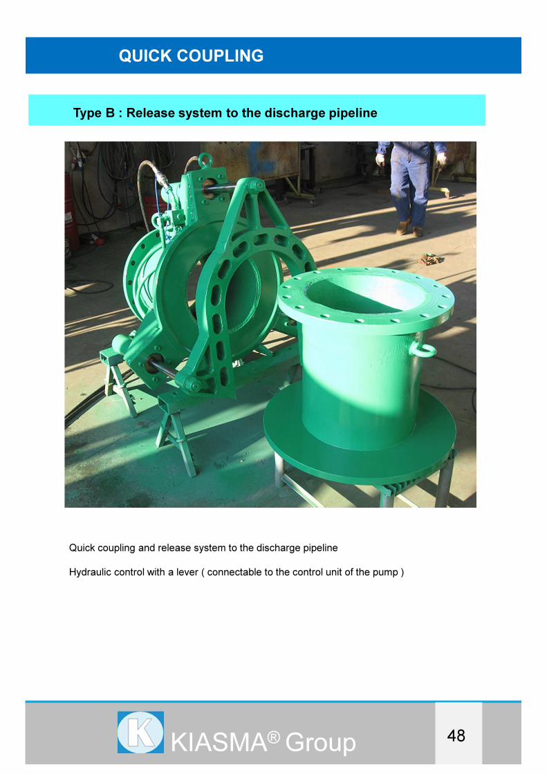
QUICK COUPLING
Type B : Release system to the discharge pipeline
Quick coupling and release system to the discharge pipeline
Hydraulic control with a lever ( connectable to the control unit of the pump )


KIASMA SRL Via Monte Adamello,31/H 31059 Zero Branco (TV) ITALY
Tel. 0039 0422 97620 Fax 0039 0422 487447
www.kiasmasrl.it [email protected]
KIASMA® Group