Embed Size (px)
Citation preview

Digital modulationDigital modulationand and
Forward error Forward error correctioncorrection

22
ModulationModulation
Modulation is the process by which some Modulation is the process by which some characteristics of a carrier signal is changed characteristics of a carrier signal is changed according to instantaneous value of another according to instantaneous value of another signal known as modulating signal.signal known as modulating signal.
Carrier signal frequency is greater than the Carrier signal frequency is greater than the modulating frequency.modulating frequency.
Typically a high frequency sinusoidal waveform Typically a high frequency sinusoidal waveform is used as carrier signal, but a square wave pulse is used as carrier signal, but a square wave pulse train may also be used.train may also be used.
33
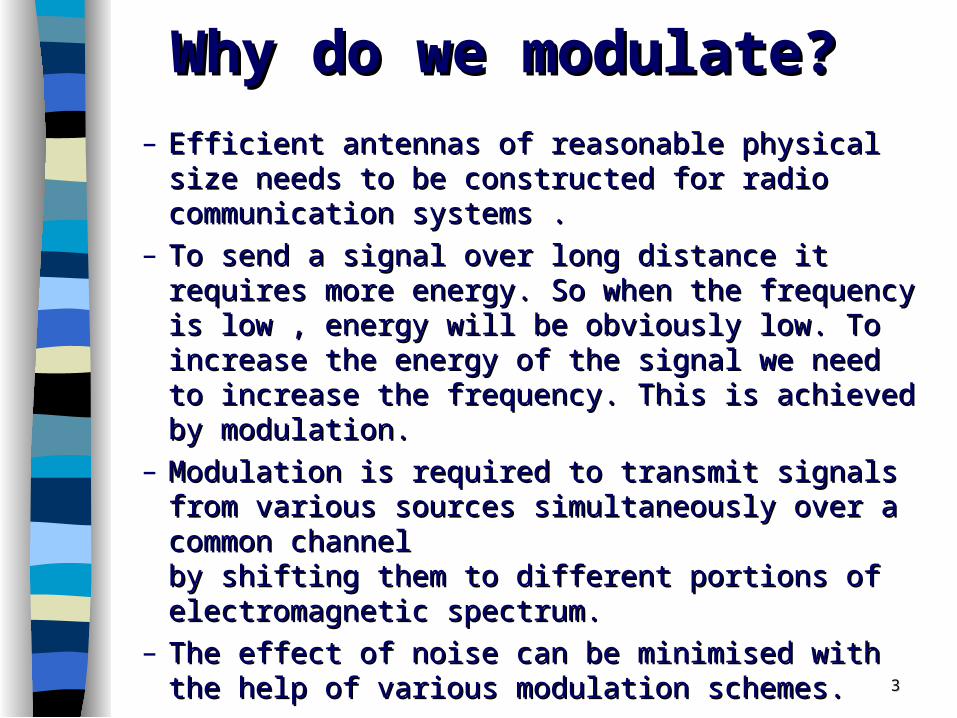
Why do we modulate?Why do we modulate?
– Efficient antennas of reasonable physical size needs Efficient antennas of reasonable physical size needs to be constructed for radio communication systems .to be constructed for radio communication systems .
– To send a signal over long distance it requires more To send a signal over long distance it requires more energy. So when the frequency is low , energy will be energy. So when the frequency is low , energy will be obviously low. To increase the energy of the signal obviously low. To increase the energy of the signal we need to increase the frequency. This is achieved we need to increase the frequency. This is achieved by modulation. by modulation.
– Modulation is required to transmit signals from Modulation is required to transmit signals from various sources simultaneously over a common various sources simultaneously over a common channelchannelby shifting them to different portions of by shifting them to different portions of electromagnetic spectrum.electromagnetic spectrum.
– The effect of noise can be minimised with the help of The effect of noise can be minimised with the help of various modulation schemes.various modulation schemes.

44
Types of modulationTypes of modulation
A n a lo gu e M od u la tion D ig ita l M o du la tion
M o d u la tion
Modulation Modulation techniques for techniques for
analogue signalsanalogue signals
Modulation Modulation techniques for techniques for digital signalsdigital signals

Analog ModulationAnalog Modulation
•When an analog modulating signalWhen an analog modulating signal is used to change the is used to change the characteristics of a carrier signal,itcharacteristics of a carrier signal,it is known as Analog Modulation.is known as Analog Modulation.
• Two types:Two types:1.1. Continuous wave modulationContinuous wave modulation e.g.AM,FM,PMe.g.AM,FM,PM2. Pulse modulation 2. Pulse modulation e.g.PAM,PWM,PPMe.g.PAM,PWM,PPM

66
Digital ModulationDigital Modulation Digital modulation is the process by which Digital modulation is the process by which
digital symbols are transformed into digital symbols are transformed into waveforms that are compatible with the waveforms that are compatible with the characteristics of the channel.characteristics of the channel.
To carry out digital modulation, we need:To carry out digital modulation, we need:– A digital A digital messagemessage or or informationinformation or or
modulatingmodulating signal and signal and– A sinusoid A sinusoid carrier wavecarrier wave or simply a or simply a carriercarrier

1)Digital modulation can easily detect and 1)Digital modulation can easily detect and correct the noise. correct the noise. 2)Digital transmission gives complete 2)Digital transmission gives complete freedom to multiplex digital data, voice freedom to multiplex digital data, voice and video giving the digital system more and video giving the digital system more flexibility than the analog system.flexibility than the analog system. 3)Digital modulated signal can traverse 3)Digital modulated signal can traverse long distance compared to analog long distance compared to analog modulation.modulation.4)Security is more in digital modulation.4)Security is more in digital modulation.5)Better quality communication.5)Better quality communication.
Advantages of digital Advantages of digital modulationmodulation

8
Basic digital Basic digital communications communications systemsystem
EM waves (modulated signal)
Modulator
Demodulator
Transmission Channel
Input transducer
Transmitter
Receiver
Output transducer
Carrier
EM waves (modulated signal)
Analog signal
analog signal
A/D
co
nver
ter
Digital signal
Err
or
corr
ect i
on
codi
ng
Err
or
dete
ctio
n/
corr
ect i
on
D/A
co
nver
ter
digital signal

99
Digital Modulation - Digital Modulation - CarrierCarrier
General form of the carrier wave isGeneral form of the carrier wave is
wherewhere
AAcc = amplitude in volts (V) = amplitude in volts (V)
cc = angular or radian frequency in rads = angular or radian frequency in rads-1-1
cc = phase in radian (rad) = phase in radian (rad)
Alternatively, since Alternatively, since
where where ffcc = frequency in hertz (Hz) = frequency in hertz (Hz)
)cos()( ccc tAtc
)2cos()( ccc tfAtc
f 2

1010
Digital modulation Digital modulation techniquestechniques
Am plitudeShift Keying
ASK
FrequencyShift Keying
FSK
PhaseShift Keying
PSK
Q uadra tureAm plitude
M odu la tion (Q AM )
D ig ital M odu la tion
Changing Changing amplitude amplitude
(A(Acc) of ) of carrier carrier
according to according to modulating modulating
signalsignal
Changing Changing phase (phase (cc) ) of carrier of carrier according according
to to modulating modulating
signalsignal
Changing Changing frequency frequency
(f(fcc) of carrier ) of carrier according to according to modulating modulating
signalsignal
Combination Combination of ASK and of ASK and
PSKPSK

1111
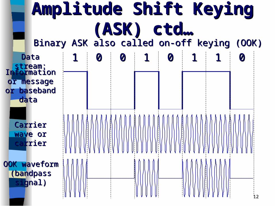
Amplitude Shift Keying Amplitude Shift Keying (ASK)(ASK)
m(t): modulating signal (baseband signal)m(t): modulating signal (baseband signal)
c(t): carrier wave (high frequency cosine)c(t): carrier wave (high frequency cosine)
m(t)m(t) y(t)y(t)
c(t)c(t)
)()()( tctmty
ASK modulator can be ASK modulator can be represented by the represented by the schematic diagram on schematic diagram on the rightthe right
ASK ASK amplitude of carrier is changed amplitude of carrier is changed according to the modulating signalaccording to the modulating signal
1212
Amplitude Shift Keying Amplitude Shift Keying (ASK) ctd…(ASK) ctd…
Binary ASK also called on-off keying (OOK)Binary ASK also called on-off keying (OOK)11 00 00 11 00 11 11 00
Information Information or message or message or baseband or baseband
data data
Carrier wave Carrier wave or carrieror carrier
Data stream:Data stream:
OOK waveform OOK waveform (bandpass (bandpass
signal)signal)

1313
Frequency Shift Keying Frequency Shift Keying (FSK)(FSK)
FSK FSK frequency of carrier is changed frequency of carrier is changed according to modulating signalaccording to modulating signal
Binary FSK (BFSK) represents ones and Binary FSK (BFSK) represents ones and zeros by carrier pulses of two distinct zeros by carrier pulses of two distinct frequencies, ffrequencies, f11 and f and f22
Binary zero Binary zero frequency f frequency f11
Binary one Binary one frequency f frequency f22

1414
Frequency Shift Keying (FSK) ctd…Frequency Shift Keying (FSK) ctd…
11 00 00 11 00 11 11 00Information Information or message or message or baseband or baseband
data data
Carrier wave Carrier wave or carrieror carrier
Data stream:Data stream:
BFSK waveform BFSK waveform (bandpass (bandpass
signal)signal)

1515
Frequency Shift Keying (FSK)Frequency Shift Keying (FSK)BFSK signal can be BFSK signal can be considered as the considered as the combination of two OOK combination of two OOK signals:signals:
1)1) One representing the One representing the baseband data stream baseband data stream {m(t)}modulated onto a {m(t)}modulated onto a carrier with frequency fcarrier with frequency f11, , andand
2)2) One representing the One representing the inverse data stream inverse data stream {m’(t)} modulated onto a {m’(t)} modulated onto a carrier with frequency fcarrier with frequency f22
cc11(t)=A cos(2(t)=A cos(2ff11t)t)
cc22(t)=A cos(2(t)=A cos(2ff22t)t)
BFSK BFSK signalsignal
m(t)m(t)
m’(t)m’(t)
Schematic of BFSK Schematic of BFSK modulator: as the modulator: as the combination of two OOK combination of two OOK signalssignals
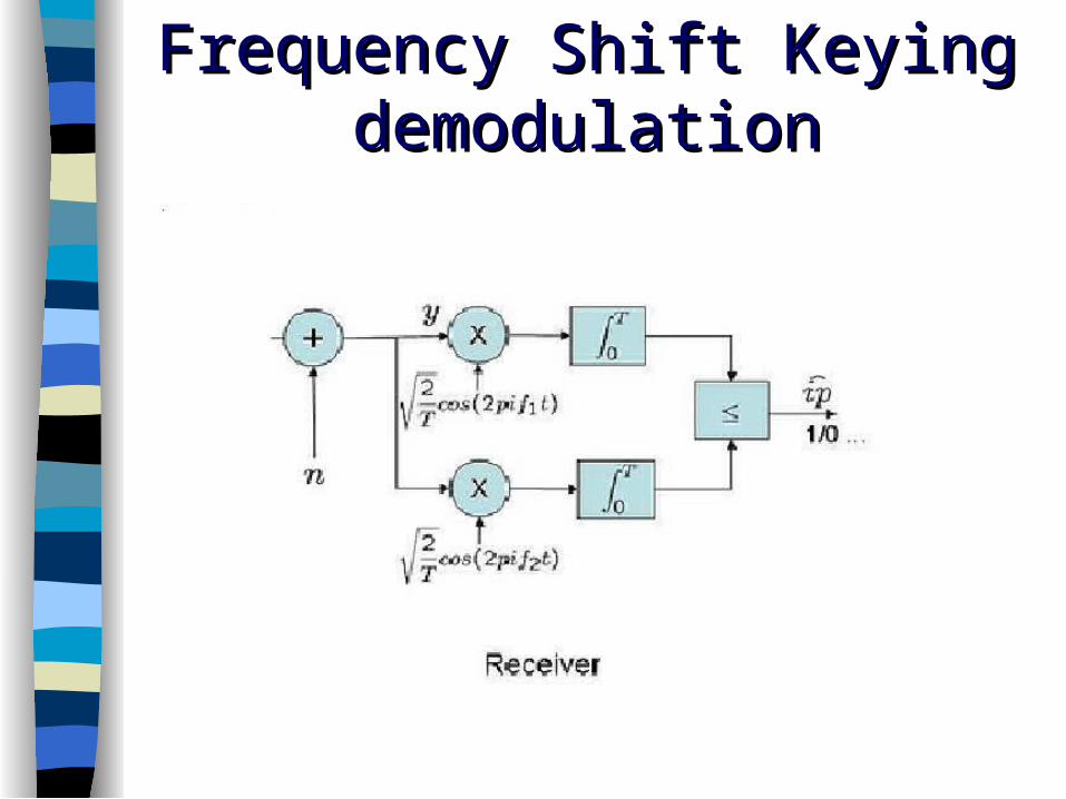
Frequency Shift Keying Frequency Shift Keying demodulationdemodulation

1717
Phase Shift Keying (PSK)Phase Shift Keying (PSK)
)2cos()( ccc tfAtc
Binary PSK (BPSK) represents ones Binary PSK (BPSK) represents ones and zeros by shifting the phase by and zeros by shifting the phase by 11 and and 22
Binary zero Binary zero phase phase 1 1 (0 rad or 0(0 rad or 0))
Binary one Binary one phase phase 2 2 (( rad or 180 rad or 180))
PSK PSK phase of carrier is changed phase of carrier is changed according to modulating signalaccording to modulating signal

1818
Phase Shift Keying (PSK) ctd…Phase Shift Keying (PSK) ctd…c= 0 rad (=0)
c= rad (=180)
t
t
c(t)
c(t+ )
t
t
c= 3/2 rad (=270)
c= /2 rad (=90)
c(t+ 3/2)
c(t+ /2)
1919
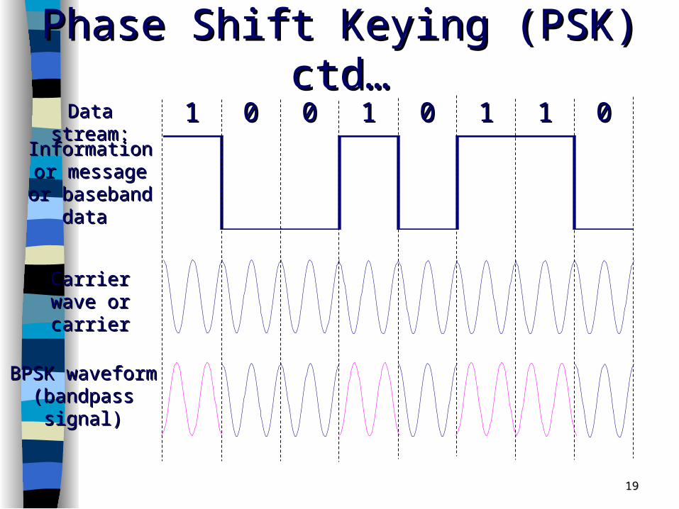
Phase Shift Keying (PSK) ctd…Phase Shift Keying (PSK) ctd…
11 00 00 11 00 11 11 00Information Information or message or message or baseband or baseband
data data
Carrier wave Carrier wave or carrieror carrier
Data stream:Data stream:
BPSK waveform BPSK waveform (bandpass (bandpass
signal)signal)

2020
BPSK: Phasor or vector diagram BPSK: Phasor or vector diagram (constellation diagram)(constellation diagram)
=0
=/2
=
=3/2
m1m2
Binary: two possible states mBinary: two possible states m11 and m and m22
Decision region 1Decision region 1Decision region 2Decision region 2
Decision boundaryDecision boundary
Euclidean Euclidean distance: distance distance: distance between two between two message pointsmessage points

2121
Quadrature Phase Shift Keying (QPSK) Quadrature Phase Shift Keying (QPSK) - Phasor or vector diagram- Phasor or vector diagram
=0
=/2
=
=3/2
m1
m2
Quadrature: four possible states mQuadrature: four possible states m11, m, m22,m,m33 and m and m44
m4
m3
Decision region 1Decision region 1
Decision region 2Decision region 2
Decision region 3Decision region 3
Decision region 4Decision region 4
Decision boundaryDecision boundary
Decision boundaryDecision boundary

2222
M-ary Phase Shift Keying (MPSK) - M-ary Phase Shift Keying (MPSK) - Phasor or vector diagramPhasor or vector diagram
=0
=/2
=
=3/2
m1
m3
M-ary: M possible states mM-ary: M possible states m11, m, m22, m, m33, … m, … mMM
m7
m5
m8m6
m4 m2
Region 1Region 1
Region 8Region 8
Region 4Region 4Region 2Region 2
Region 7Region 7
Region 3Region 3
Region 5Region 5
Region 6Region 6
Signal Signal constellation constellation
for 8-PSKfor 8-PSK
2323
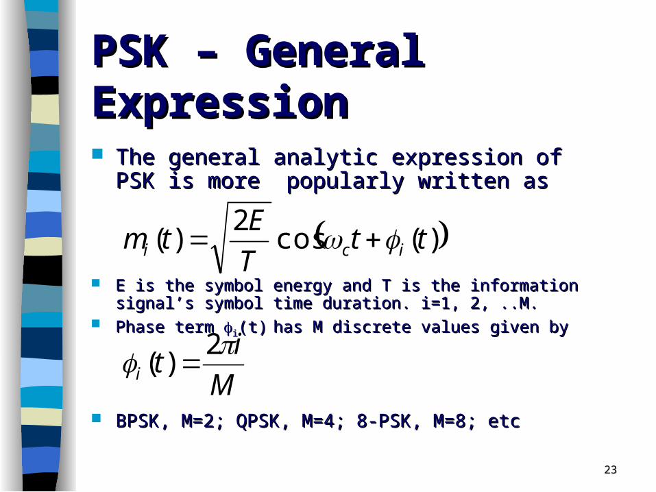
PSK – General ExpressionPSK – General Expression
The general analytic expression of PSK is more The general analytic expression of PSK is more popularly written as popularly written as
E is the symbol energy and T is the information signal’s symbol time E is the symbol energy and T is the information signal’s symbol time duration. i=1, 2, ..M. duration. i=1, 2, ..M.
Phase term Phase term ii(t)(t) has M discrete values given byhas M discrete values given by
BPSK, M=2; QPSK, M=4; 8-PSK, M=8; etc BPSK, M=2; QPSK, M=4; 8-PSK, M=8; etc
M
it
ttT
Etm
i
ici
2)(
)(cos2
)(

2424
PSK – CodingPSK – Coding
BPSK: each state (m1, m2) is represented by BPSK: each state (m1, m2) is represented by one digit (0, 1)one digit (0, 1)
QPSK: each state (m1, m2, m3, m4) is QPSK: each state (m1, m2, m3, m4) is represented by two digits (00, 01, 10, 11)represented by two digits (00, 01, 10, 11)
8PSK: each state is presented by three digits 8PSK: each state is presented by three digits (000, 001, 010, 011, 100, 101, 110, 111) (000, 001, 010, 011, 100, 101, 110, 111)
Etc… Etc…

2525
QPSK – Implementation QPSK – Implementation
By expanding the general expression, QPSK can be By expanding the general expression, QPSK can be implemented in the following way. implemented in the following way.
In QPSK the information bit stream is divided to form two In QPSK the information bit stream is divided to form two streams, in-phase (I) and in quadrature (Q), comprising of streams, in-phase (I) and in quadrature (Q), comprising of the even and odd bits of the original information signal the even and odd bits of the original information signal respectivelyrespectively
Since each transmitted symbol is represented by two Since each transmitted symbol is represented by two successive binary pulses, the symbol rate of the I and Q successive binary pulses, the symbol rate of the I and Q waveforms is half the bit rate of the information signal waveforms is half the bit rate of the information signal ((Rs=RbRs=Rb/log/log22M).M).
Subsequently the bipolar I and Q streams are used to Subsequently the bipolar I and Q streams are used to modulate the components of a carrier frequency in modulate the components of a carrier frequency in quadraturequadrature

2626
QPSK ModulatorQPSK Modulator Two carriers are in phase quadrature. Two carriers are in phase quadrature. In the case of the in phase data stream, the phase of the cosine In the case of the in phase data stream, the phase of the cosine
carrier is shifted, at symbol transitions, between 0carrier is shifted, at symbol transitions, between 0oo and 180 and 180oo
Equivalently the quadrature data stream shifts the phase of the Equivalently the quadrature data stream shifts the phase of the sine function between 90sine function between 90oo and 270 and 270oo
The modulated signals are combined linearly to produce the The modulated signals are combined linearly to produce the QPSK waveform QPSK waveform θθ(t)=(t)=00oo, 90, 90oo, 180, 180oo and 270 and 270oo

QPSK WaveformQPSK Waveform

QPSKQPSK DemodulatorDemodulator

2929
Quadrature Amplitude Modulation Quadrature Amplitude Modulation (QAM)(QAM)
Combination of ASK and PSKCombination of ASK and PSK What this actually means is that the amplitude What this actually means is that the amplitude
and the phase of the carrier wave are and the phase of the carrier wave are simultaneously changed according to the simultaneously changed according to the information you want to transmit.information you want to transmit.

3030
QAM is the encoding of information QAM is the encoding of information into a carrier wave by variation of the into a carrier wave by variation of the amplitude of both the carrier wave and amplitude of both the carrier wave and a 'quadrature' carrier that is 90° out of a 'quadrature' carrier that is 90° out of phase with the main carrier in phase with the main carrier in accordance with two input signaccordance with two input sign
Quadrature Amplitude Quadrature Amplitude Modulation (QAM)Modulation (QAM)

QAM ModulatorQAM Modulator
3131

Error Error Detection Detection and and CorrectionCorrection

Error Detection and CorrectionError Detection and Correction
Types of ErrorsTypes of Errors
DetectionDetection
Error CorrectionError Correction
Error Detection and CorrectionError Detection and Correction
Data can be corrupted during Data can be corrupted during transmission. For reliable transmission. For reliable communication, error must be detected communication, error must be detected and correctedand corrected
are implemented either at the data link are implemented either at the data link layer or the transport layer of the OSI layer or the transport layer of the OSI modelmodel

35
Error correction
Error detection
Datalink layer
PHY Layer
MAC Layer
Logic link control
Network Layer
Application Interface
Application
Transport layer

Type of ErrorsType of Errors

Type of Errors(cont’d)Type of Errors(cont’d)
Single-Bit Error is when only one bit in the Single-Bit Error is when only one bit in the data unit has changed.data unit has changed.
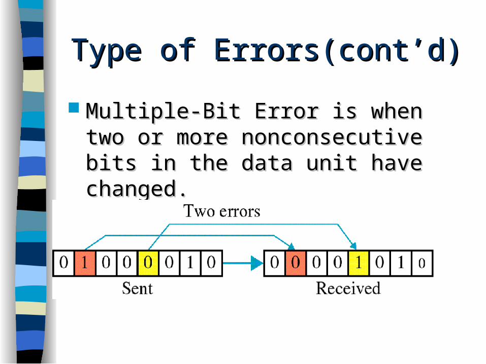
Type of Errors(cont’d)Type of Errors(cont’d)
Multiple-Bit Error is when two or more Multiple-Bit Error is when two or more nonconsecutive bits in the data unit nonconsecutive bits in the data unit have changed.have changed.

Type of Errors(cont’d)Type of Errors(cont’d) Burst Error means that two or more Burst Error means that two or more
consecutive bits in the data unit have consecutive bits in the data unit have changedchanged

DetectionDetection
Error detection uses the concept of Error detection uses the concept of redundancy, which means adding extra redundancy, which means adding extra bits for detecting errors at the bits for detecting errors at the destinationdestination

Detection(cont’d)Detection(cont’d) RedundancyRedundancy

Detection(cont’d)Detection(cont’d)
Detection methodsDetection methods– VRC(Vertical Redundancy Check)VRC(Vertical Redundancy Check)– LRC(Longitudinal Redundancy)LRC(Longitudinal Redundancy)– CRC(Cyclical redundancy Check)CRC(Cyclical redundancy Check)– ChecksumChecksum

Detection(cont’d)Detection(cont’d)
VRC(Vertical Redundancy Check)VRC(Vertical Redundancy Check)– A parity bit is added to every data unit so A parity bit is added to every data unit so
that the total number of 1s(including the that the total number of 1s(including the parity bit) becomes even for even-parity parity bit) becomes even for even-parity check or odd for odd-parity check check or odd for odd-parity check
– VRC can detect all single-bit errors. It can VRC can detect all single-bit errors. It can detect multiple-bit or burst errors only the detect multiple-bit or burst errors only the total number of errors is odd.total number of errors is odd.

Detection(cont’d)Detection(cont’d) Even parity VRC conceptEven parity VRC concept

Detection(cont’d)Detection(cont’d) LRC(Longitudinal Redundancy Check)LRC(Longitudinal Redundancy Check)
– Parity bits of all the positions are assembled Parity bits of all the positions are assembled into a new data unit, which is added to the into a new data unit, which is added to the end of the data blockend of the data block

Detection(cont’d)Detection(cont’d) CRC(Cyclic Redundancy Check)CRC(Cyclic Redundancy Check)
~ ~ is based on binary division.is based on binary division.
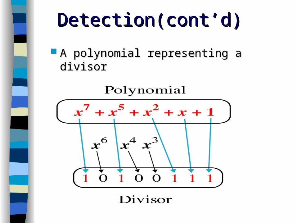
Detection(cont’d)Detection(cont’d)
A polynomial representing a divisorA polynomial representing a divisor

Detection(cont’d)Detection(cont’d) CRC generator CRC generator uses modular-2 division.uses modular-2 division.
Binary DivisionBinary Divisionin ain aCRC GeneratorCRC Generator

Detection(cont’d)Detection(cont’d)Binary DivisionBinary Divisionin ain aCRC CheckerCRC Checker

Detection(cont’d)Detection(cont’d)
ChecksumChecksum used by the higher layer protocolsused by the higher layer protocols is based on the concept of is based on the concept of
redundancy(VRC, LRC, CRC ….)redundancy(VRC, LRC, CRC ….)

Detection(cont’d)Detection(cont’d) Checksum GeneratorChecksum Generator
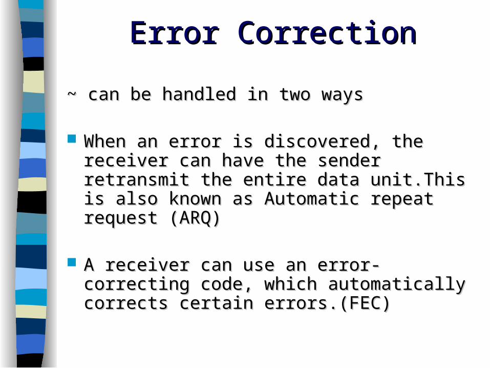
Error CorrectionError Correction
~ can be handled in two ways~ can be handled in two ways
When an error is discovered, the receiver can When an error is discovered, the receiver can have the sender retransmit the entire data have the sender retransmit the entire data unit.This is also known as Automatic repeat unit.This is also known as Automatic repeat request (ARQ)request (ARQ)
A receiver can use an error-correcting code, A receiver can use an error-correcting code, which automatically corrects certain errors.which automatically corrects certain errors.(FEC)(FEC)

Error Correction methodsError Correction methods
1.1. Hamming codesHamming codes2.2. Convolutional codesConvolutional codes3.3. Reed Solomon codesReed Solomon codes
Error Correction(cont’d)Error Correction(cont’d)

Error Correction(cont’d)Error Correction(cont’d) Hamming Code(n,k)Hamming Code(n,k) Developed by R.W.HammingDeveloped by R.W.Hamming Linear block codesLinear block codes Criteria:2Criteria:2r r >> m+r+1 m+r+1 m no. of message bitsm no. of message bits r no. of parity bitsr no. of parity bits Hamming codes can detect up to two simultaneous bit errors, Hamming codes can detect up to two simultaneous bit errors,
and correct single-bit errors.and correct single-bit errors. Positions of redundancy bits in Hamming code-:Positions of redundancy bits in Hamming code-:
Error Correction(cont’d)Error Correction(cont’d)
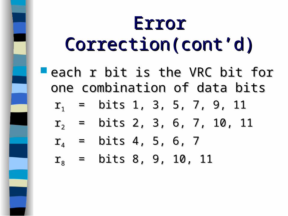
each r bit is the VRC bit for one each r bit is the VRC bit for one combination of data bitscombination of data bitsrr11 = bits 1, 3, 5, 7, 9, 11 = bits 1, 3, 5, 7, 9, 11
rr22 = bits 2, 3, 6, 7, 10, 11 = bits 2, 3, 6, 7, 10, 11
rr44 = bits 4, 5, 6, 7 = bits 4, 5, 6, 7
rr88 = bits 8, 9, 10, 11 = bits 8, 9, 10, 11

Error Correction(cont’d)Error Correction(cont’d)
Redundancy bits calculation(cont’d)Redundancy bits calculation(cont’d)
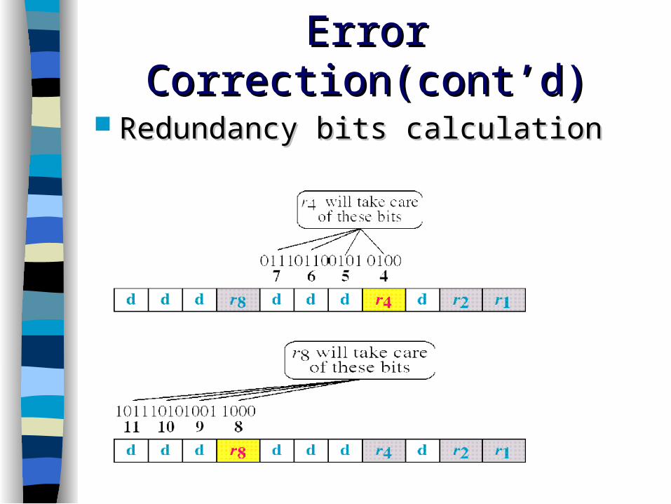
Error Correction(cont’d)Error Correction(cont’d)
Redundancy bits calculationRedundancy bits calculation

Error Correction(cont’d)Error Correction(cont’d) Calculating the r valuesCalculating the r values

Error Correction(cont’d)Error Correction(cont’d)
Error Detection and CorrectionError Detection and Correction

Error Correction(cont’d)Error Correction(cont’d) Error detection using Hamming CodeError detection using Hamming Code

Convolutional CodesConvolutional Codes Convolutional codes work on bit or symbol streams of Convolutional codes work on bit or symbol streams of
arbitrary length.arbitrary length. Error checking and correcting carried out Error checking and correcting carried out
continuouslycontinuously– ((nn, , kk, , KK) code) code
• Input processes Input processes kk bits at a time bits at a time • Output produces Output produces nn bits for every bits for every kk input bits input bits• KK = constraint factor = constraint factor• kk and and nn generally very small generally very small
– nn-bit output of (-bit output of (nn, , kk, , KK) code depends on:) code depends on:• Current block of Current block of kk input bits input bits• Previous Previous KK-1 blocks of -1 blocks of kk input bits input bits

Convolutional EncoderConvolutional Encoder

Trellis and state diagramTrellis and state diagram
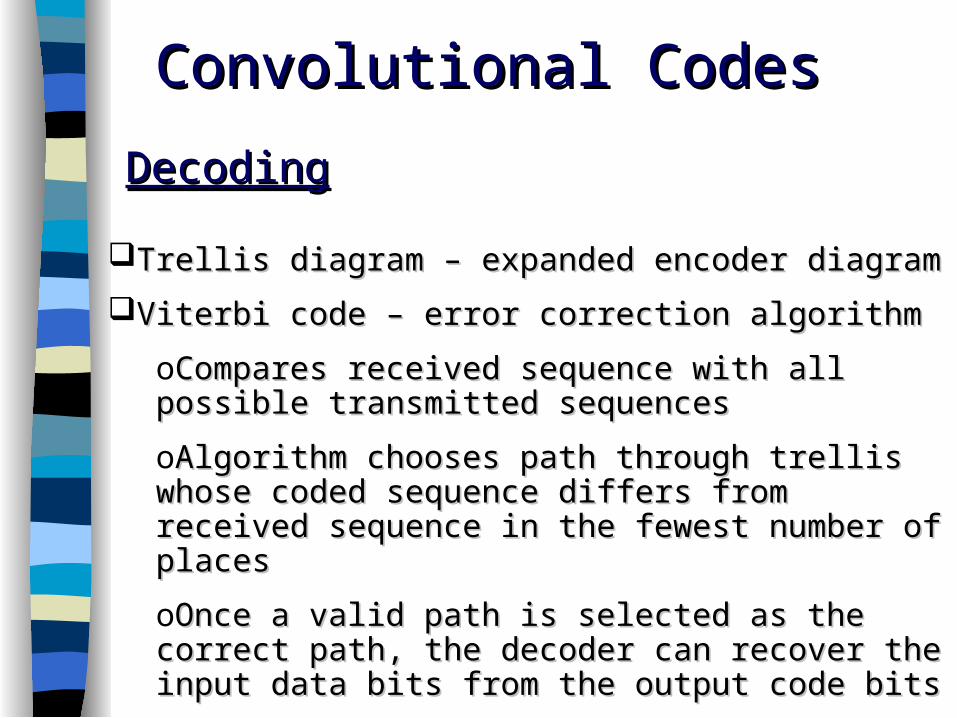
Trellis diagram – expanded encoder diagramTrellis diagram – expanded encoder diagram
Viterbi code – error correction algorithmViterbi code – error correction algorithm
oCompares received sequence with all possible Compares received sequence with all possible transmitted sequencestransmitted sequences
oAlgorithm chooses path through trellis whose coded Algorithm chooses path through trellis whose coded sequence differs from received sequence in the fewest sequence differs from received sequence in the fewest number of placesnumber of places
oOnce a valid path is selected as the correct path, the Once a valid path is selected as the correct path, the decoder can recover the input data bits from the output decoder can recover the input data bits from the output code bitscode bits
Convolutional CodesConvolutional Codes
DecodingDecoding

Convolutional codes are used extensively in numerous Convolutional codes are used extensively in numerous applications in order to achieve reliable data transfer, applications in order to achieve reliable data transfer, including including digital videodigital video, , radioradio,mobile communication, ,mobile communication, and satellite communication. These codes are often and satellite communication. These codes are often implemented in concatenation with a hard-decision code, implemented in concatenation with a hard-decision code, particularly Reed Solomon codes.particularly Reed Solomon codes.
Convolutional CodesConvolutional Codes

Reed Solomon codes are linear block codes. Reed Solomon codes are linear block codes.
Specified as RS(Specified as RS(n,kn,k).).
RS will correct code as long as 2s + r < t.RS will correct code as long as 2s + r < t.
Correct up to Correct up to t/2 t/2 errors or up toerrors or up to t t erasureserasures..
tt – –number of redundancy symbolsnumber of redundancy symbols
ss – – errors in blockerrors in block
rr – erasures in block – erasures in block
(occur when the position of an error is known.)(occur when the position of an error is known.)
Reed Solomon codes

1.1. The decoder will The decoder will detectdetect but but cannot recovercannot recover the original code word. Or:the original code word. Or:
2.2. The decoder will The decoder will mis-decodemis-decode and recover an and recover an incorrect code word without any indication.incorrect code word without any indication.
The probability of each of those cases The probability of each of those cases
depends on the specific RS code.depends on the specific RS code.
Reed Solomon codes (Cont.)
Otherwise (if Otherwise (if 2s + r < t2s + r < t is not upheld),either is not upheld),either:

Reed-Solomon codes are used to correct errors in many Reed-Solomon codes are used to correct errors in many systems including:systems including:
Storage devices (including tape, Compact Disk,Storage devices (including tape, Compact Disk,
DVD, barcodes, etc)DVD, barcodes, etc)
Wireless or mobile communications (includingWireless or mobile communications (including
cellular telephones, microwave links, etc)cellular telephones, microwave links, etc)
Satellite communicationsSatellite communications
Digital television / DVBDigital television / DVB
High-speed modems such as ADSL, xDSL, etcHigh-speed modems such as ADSL, xDSL, etc
Reed Solomon codes (Cont.)
6969
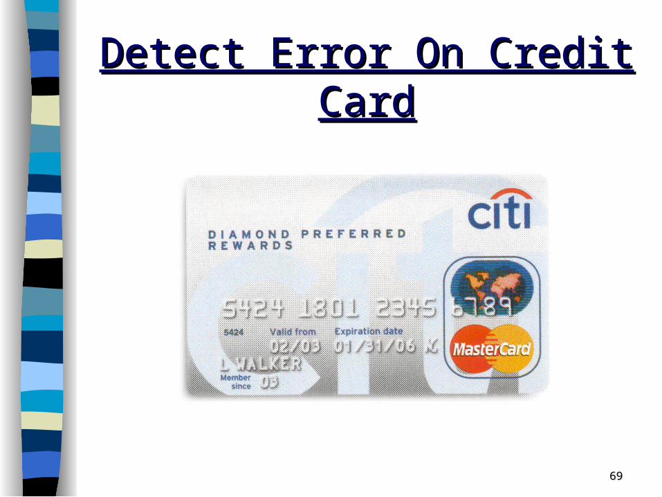
Detect Error On Credit CardDetect Error On Credit Card

7070
Detect Error On Credit CardDetect Error On Credit Card
The test performed on the credit card number is called a parity check equation. The last digit is a function of the other digits in the credit card and is called check digitcheck digit.This is how credit card numbers are generated by Visa and MasterCard. They start with an account number that is 15 digits long and use the parity check equation to find the value of the 16th digit.

•Counting from the check digit, which is the Counting from the check digit, which is the rightmost, and moving left, double the value of rightmost, and moving left, double the value of every second digit.every second digit.
•Sum the digits of the products (e.g., 10 = 1 + 0 = 1, 14 = 1 + 4 = 5) together with the undoubled digits from the original number.
•If the total modulo 10 is equal to 0 (if the total ends in zero) then the number is valid according to the Luhn formula; else it is not valid.
Formula for detecting errorFormula for detecting error
Luhn formulaLuhn formula

7272
Detect Error On Credit CardDetect Error On Credit Card
Check digit
Double and add the digits of the productDouble and add the digits of the product

7373
Now the testNow the test(8*2 + 6*2 + 4*2 + 3*2 + 0*2 + 1*2 +2*2 + 5*2) = (1+6)+(1+2)+8+6+0+2+4+(1+0)=31
(9 + 7 + 5 + 3 + 1 + 8 + 4 + 4) = 41
31 + 41 = 72 mod (10) = 2
2

THANK THANK
YOUYOU