Embed Size (px)
Citation preview
vi
* * * U R G E N T * * *INDIANA TRAINING UPDATE December 2009
PREVENTING EXCESS HYDRAULIC LOADING
Abstract: The performance and longevity of any onsite wastewater treatment system can beadversely affected by regular, sustained hydraulic loading in excess of daily design flow.Discussed below are certain design and installation techniques which can prevent onsite systemsfrom being flooded by surface and/or ground water flows. Saturated conditions are detrimental tothe function of the Enviro-Septic® System, which relies on aerobic conditions to performoptimally.
Background: During recent inspections of Enviro-Septic® Systems in Indiana, a pattern ofcommon installation errors became apparent. While these errors would be detrimental to anyonsite system’s function, this Technical Bulletin will focus on how these factors impact Enviro-Septic® Systems and how such problems can be corrected and/or avoided in future installations.Onsite systems are sized based on the expected amount of effluent they will treat on a dailybasis, which is referred to as “daily design flow.” It is important to ensure that each system isadequately sized, taking into consideration the actual number of occupants (if this increases flowsbeyond the daily design flow) and whether the system will be subjected to additional loading fromjetted tubs, water softeners, water purifiers, etc. The volumes of water utilized by such fixturesand appliances should be included in design daily flow calculations in order to size a systemproperly. Onsite systems are not designed to handle additional water from roof drains, foundationdrains, sump pumps, irrigations systems, gutter systems, etc. Since the water from such systemsdoes not require treatment, it can be safely dispersed in a location where it will not impact theonsite system.
Common Causes of Excessive Hydraulic Loading: While an onsite system can easily handleisolated, occasional surges in volume either of effluent or storm water runoff, prolonged dosing inexcess of what the system was designed to handle can be problematic. Some of the morecommon sources of excess hydraulic loading discovered were the result of drain or guttersystems discharging into or near the treatment field, inadequate perimeter drains, ineffectivesurface diversion/swale installations, and leaking septic tank connections. Recent inspections ofEnviro-Septic® systems in Daviess County by the Daviess County Health Department, ISDH,Presby Environmental and Environmental Septic Solutions revealed that these were the mostcommon installation errors contributing to hydraulic overloading of onsite systems.
Also, leaks in the plumbing system can also result in overloading the onsite system and should berepaired immediately. Care should also be taken to ensure that the septic tank and all of itsconnections, access ports, risers, etc. are properly sealed and watertight to prevent ground waterfrom infiltrating and overburdening the system.
Lowering Ground Water with Perimeter Drains: For Indiana sites where the seasonal highwater table (“SHWT”) is too close to the surface, a perimeter drain can be used to lower theSHWT. NOTE: It is preferable in such situations to design an elevated system rather thanattempt to lower the SHWT with a drain. However, there are times when even an elevatedsystem may require a perimeter drain to lower the SHWT. In all cases where a perimeter drain isrequired, it is crucial that the drain be located and constructed properly. Please see attachedPerimeter Drain Notes. A properly constructed perimeter drain surrounds the system on all four
800-473-5298 www.presbyenvironmental.comPRESBY ENVIRONMENTAL, INC.
TECHNICAL BULLETIN
vii
sides and is a minimum of 10 ft. away from the outer edges of the System Sand bed. Ongoingmaintenance by the owner to ensure that the outlet remains unobstructed is essential to properfunctioning; animal guards are required on the drain outlet to prevent animal activity that couldresult in obstruction. No other drainage systems (such as foundation drains, sump pumps, etc.)should be incorporated into the perimeter drain design or discharge in the area of the onsitesystem.
Redirecting Surface Water Flows with Diversions and Proper Grading: In selecting thelocation of the onsite system, it is important to consider the surrounding topography and select asite where surface and subsurface waters do not naturally converge. Adequate soil covermaterial (loam/topsoil, minimum of 6 in. deep) must be installed above the System Sand; thiscover material should be “crowned” to direct surface waters away from the system. Crowning is avery simple procedure: simply make the center of the system area the “high” point and grade thecover material so it gently slopes away from the center; keep in mind there will be some naturalsettling of cover material. We have found that poor final grading, or using less than the requiredamount of soil cover above a system, results in “pockets” which hold surface water, allowing it toinfiltrate the system and possibly cause saturation. After final grading, the site must be seededand mulched or sodded immediately to prevent erosion; only shallow-rooted vegetation such asgrass or wildflowers should be planted above an onsite system. There should be no trees orgardens planted within ten (10) feet of the system; the State of Indiana does not permit“hardscape” (paving, patios, driveways, parking lots, etc.) to be installed above the system.
Swales are another means of directing surface water away from the system. Swales are installedin undisturbed soil in order to intercept and divert surface water flows away from the system.They should be located a minimum of 10 ft. from the outer edge of the System Sand bed (if aperimeter drain is used, the swale is located above or immediately upslope from the perimeterdrain area). Swales must have a positive grade of at least 0.2 feet per 100 feet to preventstanding water. Swales should be sufficiently deep to redirect surface water away from thetreatment field effectively. (Please see attached Perimeter Drain Notes.) It is also important toexplain the purpose of swales to the system owner so they will not alter them or backfill them.The Monroe County Indiana Health Department recently issued a directive making swalesmandatory if a perimeter drain is used. They also stressed the importance of explaining thepurpose of swales to the system owner, since in many cases properly installed swales are filled inby homeowners or landscapers who do not understand how critical these surface diversions areto the onsite system’s function.
Conclusion: Proper site selection, accurate sizing, adequate perimeter drains, and well-constructed surface diversions (grading and swales) are effective in preventing excess hydraulicloading to onsite systems. Prolonged saturated conditions compromise the function of all onsitesystems and measures should be taken to redirect ground and surface water away from thetreatment field. Homeowners should be made aware of the importance of dispersing water otherthan wastewater away from the onsite system. If you have any questions about the information inthis Training Update, please contact Presby Environmental or Environmental Septic Solutions fortechnical assistance and further guidance.
Prepared by,Presby Environmental, Inc.143 Airport RoadWhitefield, NH 03598(800) 473-5298email: [email protected] Septic Solutions, Inc.16 West Jennings StreetNewburgh, IN 47630(812) 457-3144 (cell – Michael P. Market)email: [email protected]
viii
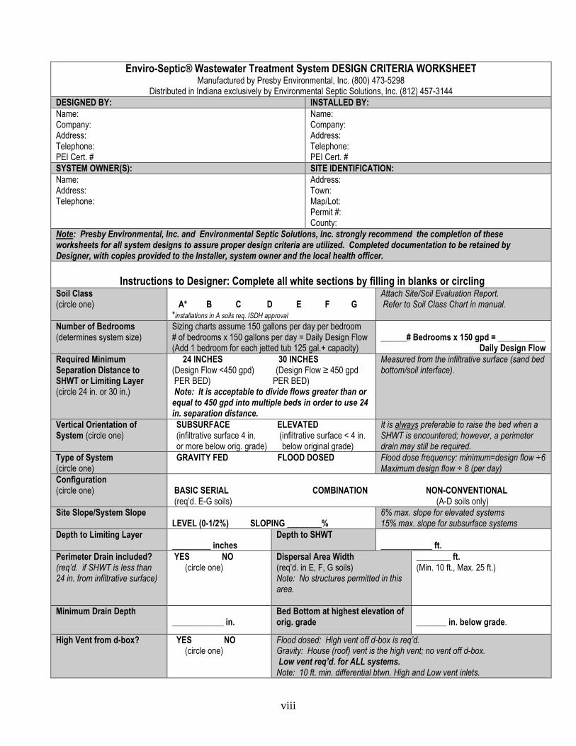
Enviro-Septic® Wastewater Treatment System DESIGN CRITERIA WORKSHEETManufactured by Presby Environmental, Inc. (800) 473-5298
Distributed in Indiana exclusively by Environmental Septic Solutions, Inc. (812) 457-3144DESIGNED BY: INSTALLED BY:Name:Company:Address:Telephone:PEI Cert. #
Name:Company:Address:Telephone:PEI Cert. #
SYSTEM OWNER(S): SITE IDENTIFICATION:Name:Address:Telephone:
Address:Town:Map/Lot:Permit #:County:
Note: Presby Environmental, Inc. and Environmental Septic Solutions, Inc. strongly recommend the completion of theseworksheets for all system designs to assure proper design criteria are utilized. Completed documentation to be retained byDesigner, with copies provided to the Installer, system owner and the local health officer.
Instructions to Designer: Complete all white sections by filling in blanks or circlingSoil Class(circle one) A* B C D E F G
*installations in A soils req. ISDH approval
Attach Site/Soil Evaluation Report.Refer to Soil Class Chart in manual.
Number of Bedrooms(determines system size)
Sizing charts assume 150 gallons per day per bedroom# of bedrooms x 150 gallons per day = Daily Design Flow(Add 1 bedroom for each jetted tub 125 gal.+ capacity)
______# Bedrooms x 150 gpd = ___________Daily Design Flow
Required MinimumSeparation Distance toSHWT or Limiting Layer(circle 24 in. or 30 in.)
24 INCHES 30 INCHES(Design Flow <450 gpd) (Design Flow ≥ 450 gpdPER BED) PER BED)Note: It is acceptable to divide flows greater than or
equal to 450 gpd into multiple beds in order to use 24in. separation distance.
Measured from the infiltrative surface (sand bedbottom/soil interface).
Vertical Orientation ofSystem (circle one)
SUBSURFACE ELEVATED(infiltrative surface 4 in. (infiltrative surface < 4 in.or more below orig. grade) below original grade)
It is always preferable to raise the bed when aSHWT is encountered; however, a perimeterdrain may still be required.
Type of System(circle one)
GRAVITY FED FLOOD DOSED Flood dose frequency: minimum=design flow ÷6Maximum design flow ÷ 8 (per day)
Configuration(circle one) BASIC SERIAL COMBINATION NON-CONVENTIONAL
(req’d. E-G soils) (A-D soils only)Site Slope/System Slope
LEVEL (0-1/2%) SLOPING ________%6% max. slope for elevated systems15% max. slope for subsurface systems
Depth to Limiting Layer_________ inches
Depth to SHWT____________ ft.
Perimeter Drain included?(req’d. if SHWT is less than24 in. from infiltrative surface)
YES NO(circle one)
Dispersal Area Width(req’d. in E, F, G soils)Note: No structures permitted in thisarea.
________ ft.(Min. 10 ft., Max. 25 ft.)
Minimum Drain Depth____________ in.
Bed Bottom at highest elevation oforig. grade _______ in. below grade.
High Vent from d-box? YES NO(circle one)
Flood dosed: High vent off d-box is req’d.Gravity: House (roof) vent is the high vent; no vent off d-box.Low vent req’d. for ALL systems.
Note: 10 ft. min. differential btwn. High and Low vent inlets.
ix
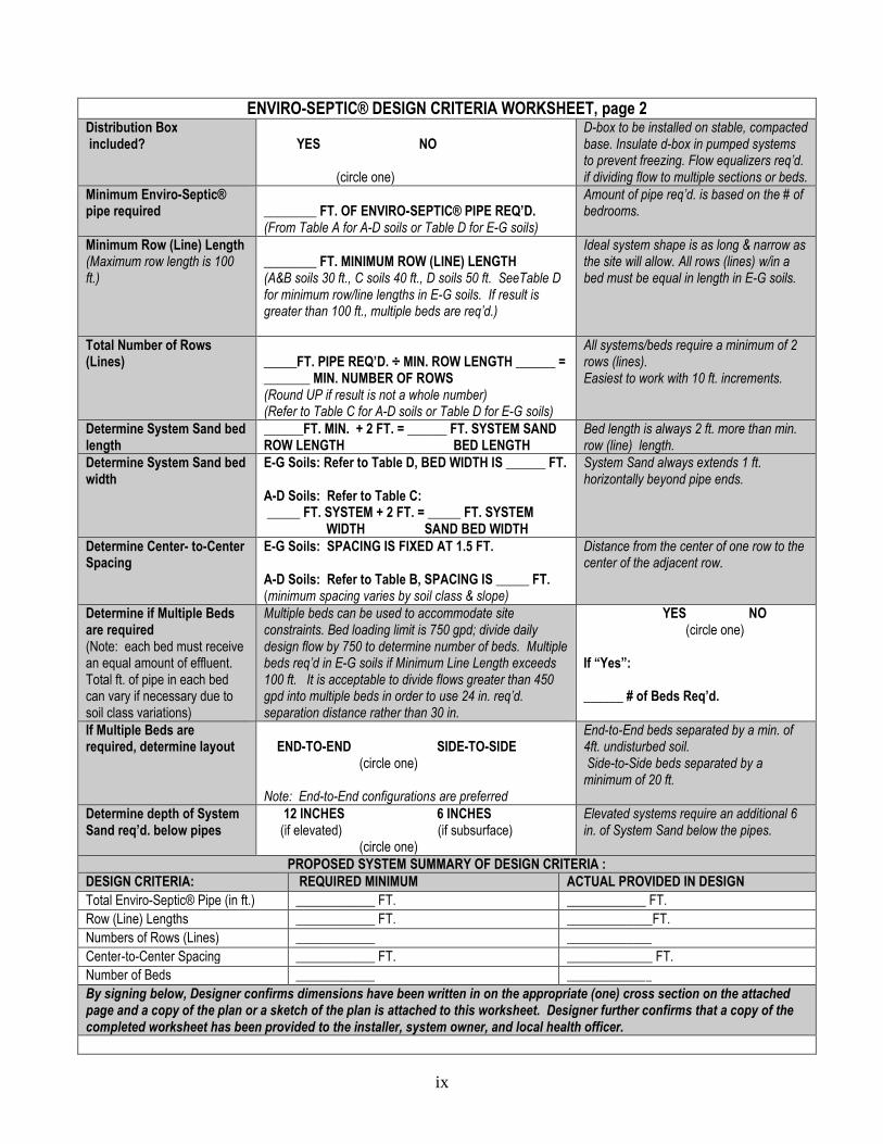
ENVIRO-SEPTIC® DESIGN CRITERIA WORKSHEET, page 2Distribution Boxincluded? YES NO
(circle one)
D-box to be installed on stable, compactedbase. Insulate d-box in pumped systemsto prevent freezing. Flow equalizers req’d.if dividing flow to multiple sections or beds.
Minimum Enviro-Septic®pipe required ________ FT. OF ENVIRO-SEPTIC® PIPE REQ’D.
(From Table A for A-D soils or Table D for E-G soils)
Amount of pipe req’d. is based on the # ofbedrooms.
Minimum Row (Line) Length(Maximum row length is 100ft.)
________ FT. MINIMUM ROW (LINE) LENGTH(A&B soils 30 ft., C soils 40 ft., D soils 50 ft. SeeTable Dfor minimum row/line lengths in E-G soils. If result isgreater than 100 ft., multiple beds are req’d.)
Ideal system shape is as long & narrow asthe site will allow. All rows (lines) w/in abed must be equal in length in E-G soils.
Total Number of Rows(Lines) _____FT. PIPE REQ’D. ÷ MIN. ROW LENGTH ______ =
_______ MIN. NUMBER OF ROWS(Round UP if result is not a whole number)(Refer to Table C for A-D soils or Table D for E-G soils)
All systems/beds require a minimum of 2rows (lines).Easiest to work with 10 ft. increments.
Determine System Sand bedlength
______FT. MIN. + 2 FT. = ______ FT. SYSTEM SANDROW LENGTH BED LENGTH
Bed length is always 2 ft. more than min.row (line) length.
Determine System Sand bedwidth
E-G Soils: Refer to Table D, BED WIDTH IS ______ FT.
A-D Soils: Refer to Table C:_____ FT. SYSTEM + 2 FT. = _____ FT. SYSTEM
WIDTH SAND BED WIDTH
System Sand always extends 1 ft.horizontally beyond pipe ends.
Determine Center- to-CenterSpacing
E-G Soils: SPACING IS FIXED AT 1.5 FT.
A-D Soils: Refer to Table B, SPACING IS _____ FT.(minimum spacing varies by soil class & slope)
Distance from the center of one row to thecenter of the adjacent row.
Determine if Multiple Bedsare required(Note: each bed must receivean equal amount of effluent.Total ft. of pipe in each bedcan vary if necessary due tosoil class variations)
Multiple beds can be used to accommodate siteconstraints. Bed loading limit is 750 gpd; divide dailydesign flow by 750 to determine number of beds. Multiplebeds req’d in E-G soils if Minimum Line Length exceeds100 ft. It is acceptable to divide flows greater than 450gpd into multiple beds in order to use 24 in. req’d.separation distance rather than 30 in.
YES NO(circle one)
If “Yes”:
______ # of Beds Req’d.
If Multiple Beds arerequired, determine layout END-TO-END SIDE-TO-SIDE
(circle one)
Note: End-to-End configurations are preferred
End-to-End beds separated by a min. of4ft. undisturbed soil.Side-to-Side beds separated by a
minimum of 20 ft.
Determine depth of SystemSand req’d. below pipes
12 INCHES 6 INCHES(if elevated) (if subsurface)
(circle one)
Elevated systems require an additional 6in. of System Sand below the pipes.
PROPOSED SYSTEM SUMMARY OF DESIGN CRITERIA :DESIGN CRITERIA: REQUIRED MINIMUM ACTUAL PROVIDED IN DESIGN
Total Enviro-Septic® Pipe (in ft.) ____________ FT. ____________ FT.
Row (Line) Lengths ____________ FT. _____________FT.
Numbers of Rows (Lines) ____________ _____________
Center-to-Center Spacing ____________ FT. _____________ FT.
Number of Beds ____________ _____________
By signing below, Designer confirms dimensions have been written in on the appropriate (one) cross section on the attachedpage and a copy of the plan or a sketch of the plan is attached to this worksheet. Designer further confirms that a copy of thecompleted worksheet has been provided to the installer, system owner, and local health officer.

x
Signed: ________________________________________________ Dated: _________________________(Print Name Here: ) PEI Cert. #: ______________________In the space below, sketch the Enviro-Septic® System design, including references to structures or otherbenchmarks to indicate system location on the site. Indicate “As Built” changes. Retain a copy with systemdocumentation and provide a copy to the System Owner.
Site Address:________________________________ System Owner(s): _______________________Installer’s Name: ____________________________ Date of Installation: _____________________
* NOT TO SCALE UNLESS NOTED*
xi
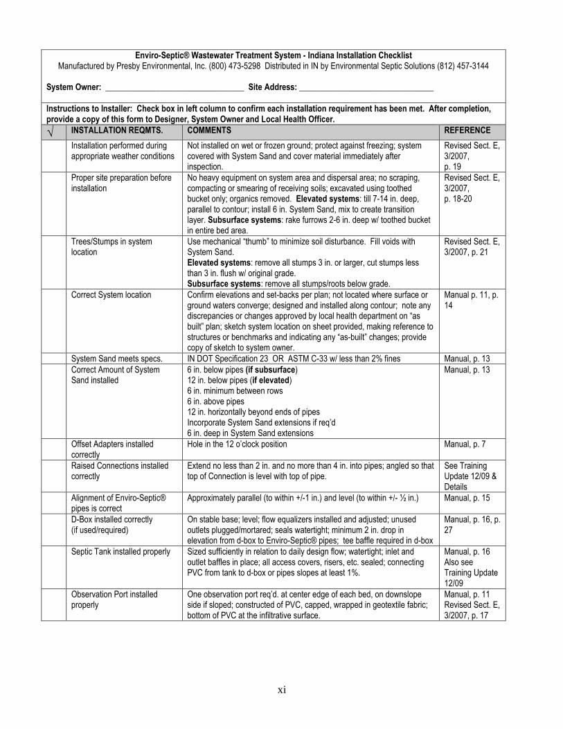
Enviro-Septic® Wastewater Treatment System - Indiana Installation ChecklistManufactured by Presby Environmental, Inc. (800) 473-5298 Distributed in IN by Environmental Septic Solutions (812) 457-3144
System Owner: _________________________________ Site Address: ________________________________
Instructions to Installer: Check box in left column to confirm each installation requirement has been met. After completion,provide a copy of this form to Designer, System Owner and Local Health Officer.
√ INSTALLATION REQMTS. COMMENTS REFERENCE
Installation performed duringappropriate weather conditions
Not installed on wet or frozen ground; protect against freezing; systemcovered with System Sand and cover material immediately afterinspection.
Revised Sect. E,3/2007,p. 19
Proper site preparation beforeinstallation
No heavy equipment on system area and dispersal area; no scraping,compacting or smearing of receiving soils; excavated using toothedbucket only; organics removed. Elevated systems: till 7-14 in. deep,parallel to contour; install 6 in. System Sand, mix to create transitionlayer. Subsurface systems: rake furrows 2-6 in. deep w/ toothed bucketin entire bed area.
Revised Sect. E,3/2007,p. 18-20
Trees/Stumps in systemlocation
Use mechanical “thumb” to minimize soil disturbance. Fill voids withSystem Sand.Elevated systems: remove all stumps 3 in. or larger, cut stumps lessthan 3 in. flush w/ original grade.Subsurface systems: remove all stumps/roots below grade.
Revised Sect. E,3/2007, p. 21
Correct System location Confirm elevations and set-backs per plan; not located where surface orground waters converge; designed and installed along contour; note anydiscrepancies or changes approved by local health department on “asbuilt” plan; sketch system location on sheet provided, making reference tostructures or benchmarks and indicating any “as-built” changes; providecopy of sketch to system owner.
Manual p. 11, p.14
System Sand meets specs. IN DOT Specification 23 OR ASTM C-33 w/ less than 2% fines Manual, p. 13Correct Amount of SystemSand installed
6 in. below pipes (if subsurface)12 in. below pipes (if elevated)6 in. minimum between rows6 in. above pipes12 in. horizontally beyond ends of pipesIncorporate System Sand extensions if req’d6 in. deep in System Sand extensions
Manual, p. 13
Offset Adapters installedcorrectly
Hole in the 12 o’clock position Manual, p. 7
Raised Connections installedcorrectly
Extend no less than 2 in. and no more than 4 in. into pipes; angled so thattop of Connection is level with top of pipe.
See TrainingUpdate 12/09 &Details
Alignment of Enviro-Septic®pipes is correct
Approximately parallel (to within +/-1 in.) and level (to within +/- ½ in.) Manual, p. 15
D-Box installed correctly(if used/required)
On stable base; level; flow equalizers installed and adjusted; unusedoutlets plugged/mortared; seals watertight; minimum 2 in. drop inelevation from d-box to Enviro-Septic® pipes; tee baffle required in d-box
Manual, p. 16, p.27
Septic Tank installed properly Sized sufficiently in relation to daily design flow; watertight; inlet andoutlet baffles in place; all access covers, risers, etc. sealed; connectingPVC from tank to d-box or pipes slopes at least 1%.
Manual, p. 16Also seeTraining Update12/09
Observation Port installedproperly
One observation port req’d. at center edge of each bed, on downslopeside if sloped; constructed of PVC, capped, wrapped in geotextile fabric;bottom of PVC at the infiltrative surface.
Manual, p. 11Revised Sect. E,3/2007, p. 17
xii
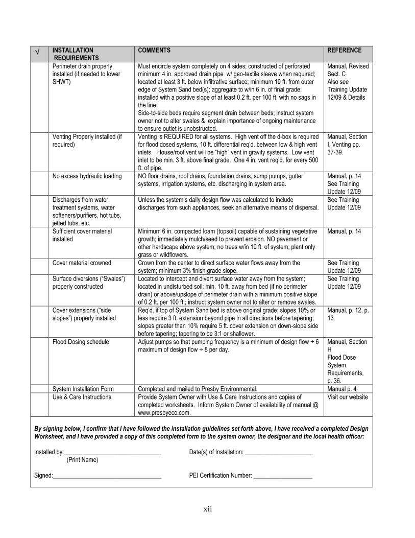
√ INSTALLATIONREQUIREMENTS
COMMENTS REFERENCE
Perimeter drain properlyinstalled (if needed to lowerSHWT)
Must encircle system completely on 4 sides; constructed of perforatedminimum 4 in. approved drain pipe w/ geo-textile sleeve when required;located at least 3 ft. below infiltrative surface; minimum 10 ft. from outeredge of System Sand bed(s); aggregate to w/in 6 in. of final grade;installed with a positive slope of at least 0.2 ft. per 100 ft. with no sags inthe line.Side-to-side beds require segment drain between beds; instruct systemowner not to alter swales & explain importance of ongoing maintenanceto ensure outlet is unobstructed.
Manual, RevisedSect. CAlso seeTraining Update12/09 & Details
Venting Properly installed (ifrequired)
Venting is REQUIRED for all systems. High vent off the d-box is requiredfor flood dosed systems, 10 ft. differential req’d. between low & high ventinlets. House/roof vent will be “high” vent in gravity systems. Low ventinlet to be min. 3 ft. above final grade. One 4 in. vent req’d. for every 500ft. of pipe.
Manual, SectionI, Venting pp.37-39.
No excess hydraulic loading NO floor drains, roof drains, foundation drains, sump pumps, guttersystems, irrigation systems, etc. discharging in system area.
Manual, p. 14See TrainingUpdate 12/09
Discharges from watertreatment systems, watersofteners/purifiers, hot tubs,jetted tubs, etc.
Unless the system’s daily design flow was calculated to includedischarges from such appliances, seek an alternative means of dispersal.
See TrainingUpdate 12/09
Sufficient cover materialinstalled
Minimum 6 in. compacted loam (topsoil) capable of sustaining vegetativegrowth; immediately mulch/seed to prevent erosion. NO pavement orother hardscape above system; no trees w/in 10 ft. of system; plant onlygrass or wildflowers.
Manual, p. 14
Cover material crowned Crown from the center to direct surface water flows away from thesystem; minimum 3% finish grade slope.
See TrainingUpdate 12/09
Surface diversions (“Swales”)properly constructed
Located to intercept and divert surface water away from the system;located in undisturbed soil; min. 10 ft. away from bed (if no perimeterdrain) or above/upslope of perimeter drain with a minimum positive slopeof 0.2 ft. per 100 ft.; instruct system owner not to alter or remove swales.
See TrainingUpdate 12/09
Cover extensions (“sideslopes”) properly installed
Req’d. if top of System Sand bed is above original grade; slopes 10% orless require 3 ft. extension beyond pipe in all directions before tapering;slopes greater than 10% require 5 ft. cover extension on down-slope sidebefore tapering; tapering to be 3:1 or shallower.
Manual, p. 12, p.13
Flood Dosing schedule Adjust pumps so that pumping frequency is a minimum of design flow ÷ 6maximum of design flow ÷ 8 per day.
Manual, SectionHFlood DoseSystemRequirements,p. 36.
System Installation Form Completed and mailed to Presby Environmental. Manual p. 4Use & Care Instructions Provide System Owner with Use & Care Instructions and copies of
completed worksheets. Inform System Owner of availability of manual @www.presbyeco.com.
Visit our website
By signing below, I confirm that I have followed the installation guidelines set forth above, I have received a completed DesignWorksheet, and I have provided a copy of this completed form to the system owner, the designer and the local health officer:
Installed by: _______________________________ Date(s) of Installation: ______________________(Print Name)
Signed:___________________________________ PEI Certification Number: ___________________
xiii
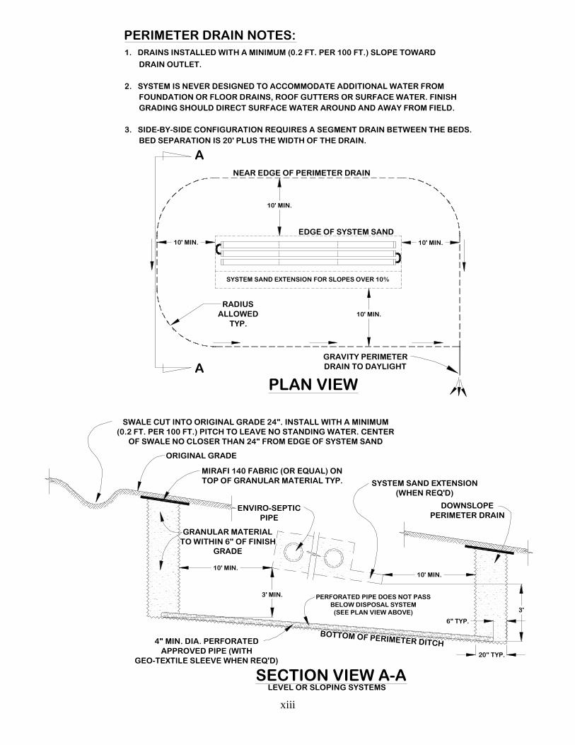
PERIMETER DRAIN NOTES:1. DRAINS INSTALLED WITH A MINIMUM (0.2 FT. PER 100 FT.) SLOPE TOWARD
DRAIN OUTLET.
2. SYSTEM IS NEVER DESIGNED TO ACCOMMODATE ADDITIONAL WATER FROM
FOUNDATION OR FLOOR DRAINS, ROOF GUTTERS OR SURFACE WATER. FINISH
GRADING SHOULD DIRECT SURFACE WATER AROUND AND AWAY FROM FIELD.
3. SIDE-BY-SIDE CONFIGURATION REQUIRES A SEGMENT DRAIN BETWEEN THE BEDS.
BED SEPARATION IS 20' PLUS THE WIDTH OF THE DRAIN.
SYSTEM SAND EXTENSION FOR SLOPES OVER 10%
PLAN VIEW
10' MIN.
10' MIN.
GRAVITY PERIMETERDRAIN TO DAYLIGHT
NEAR EDGE OF PERIMETER DRAIN
RADIUSALLOWED
TYP.
EDGE OF SYSTEM SAND
10' MIN.
3' MIN.
4" MIN. DIA. PERFORATEDAPPROVED PIPE (WITH
GEO-TEXTILE SLEEVE WHEN REQ'D)
GRANULAR MATERIALTO WITHIN 6" OF FINISH
GRADE
MIRAFI 140 FABRIC (OR EQUAL) ONTOP OF GRANULAR MATERIAL TYP.
ORIGINAL GRADE
SWALE CUT INTO ORIGINAL GRADE 24". INSTALL WITH A MINIMUM(0.2 FT. PER 100 FT.) PITCH TO LEAVE NO STANDING WATER. CENTER
OF SWALE NO CLOSER THAN 24" FROM EDGE OF SYSTEM SAND
ENVIRO-SEPTICPIPE
10' MIN.
BOTTOM OF PERIMETER DITCH
3'
SECTION VIEW A-A
20" TYP.
6" TYP.
LEVEL OR SLOPING SYSTEMS
DOWNSLOPEPERIMETER DRAIN
SYSTEM SAND EXTENSION(WHEN REQ'D)
A
A
PERFORATED PIPE DOES NOT PASSBELOW DISPOSAL SYSTEM
(SEE PLAN VIEW ABOVE)
10' MIN. 10' MIN.
xiv
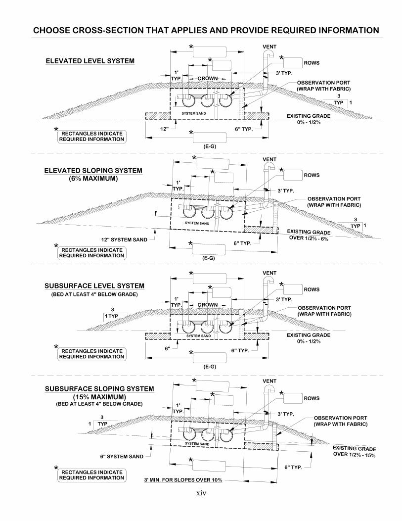
3
1
SYSTEM SAND
TYP
1'TYP.
3' TYP.
12"
ROWS
(E-G)
6" TYP.
1
SYSTEM SAND
1'TYP.
3' TYP.
6"
ROWS
(E-G)
6" TYP.
EXISTING GRADE0% - 1/2%
EXISTING GRADE0% - 1/2%
SUBSURFACE LEVEL SYSTEM
ELEVATED LEVEL SYSTEM
31
SYSTEM SANDTYP
1'TYP. 3' TYP.
12" SYSTEM SAND
ROWS
(E-G)
6" TYP.
EXISTING GRADEOVER 1/2% - 6%
ELEVATED SLOPING SYSTEM(6% MAXIMUM)
SYSTEM SAND
1'TYP.
3' TYP.
6" SYSTEM SAND
ROWS
6" TYP.
EXISTING GRADEOVER 1/2% - 15%
SUBSURFACE SLOPING SYSTEM(15% MAXIMUM)
(BED AT LEAST 4" BELOW GRADE)
(BED AT LEAST 4" BELOW GRADE)
3' MIN. FOR SLOPES OVER 10%
CROWN
CROWN
OBSERVATION PORT(WRAP WITH FABRIC)
OBSERVATION PORT(WRAP WITH FABRIC)
OBSERVATION PORT(WRAP WITH FABRIC)
3
TYP
1
3
TYPOBSERVATION PORT(WRAP WITH FABRIC)
VENT
VENT
VENT
VENT
*
* *
*
*
* *
*
*
* *
*
*
* *
*
REQUIRED INFORMATIONRECTANGLES INDICATE*
CHOOSE CROSS-SECTION THAT APPLIES AND PROVIDE REQUIRED INFORMATION
REQUIRED INFORMATIONRECTANGLES INDICATE*
* RECTANGLES INDICATEREQUIRED INFORMATION
* RECTANGLES INDICATEREQUIRED INFORMATION
xv
TEE BAFFLE DETAIL
TEE BAFFLE
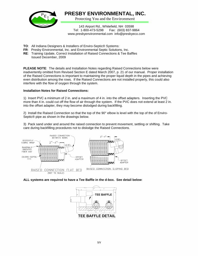
TO: All Indiana Designers & Installers of Enviro-Septic® Systems:FR: Presby Environmental, Inc. and Environmental Septic Solutions, Inc.RE: Training Update, Correct Installation of Raised Connections & Tee Baffles
Issued December, 2009
PLEASE NOTE: The details and Installation Notes regarding Raised Connections below wereinadvertently omitted from Revised Section E dated March 2007, p. 21 of our manual. Proper installationof the Raised Connections is important to maintaining the proper liquid depth in the pipes and achievingeven distribution among the rows. If the Raised Connections are not installed properly, this could alsointerfere with the flow of oxygen through the system.
Installation Notes for Raised Connections:
1) Insert PVC a minimum of 2 in. and a maximum of 4 in. into the offset adapters. Inserting the PVCmore than 4 in. could cut off the flow of air through the system. If the PVC does not extend at least 2 in.into the offset adapter, they may become dislodged during backfilling.
2) Install the Raised Connection so that the top of the 90° elbow is level with the top of the of Enviro-Septic® pipe as shown in the drawings below.
3) Pack sand under and around the raised connection to prevent movement, settling or shifting. Takecare during backfilling procedures not to dislodge the Raised Connections.
ALL systems are required to have a Tee Baffle in the d-box. See detail below:
Protecting You and the EnvironmentPRESBY ENVIRONMENTAL, INC.
143 Airport Rd., Whitefield, NH 03598Tel: 1-800-473-5298 Fax: (603) 837-9864
www.presbyenvironmental.com [email protected]