Embed Size (px)
Citation preview

C H A P T E R
2-1Cisco Nexus 7000 Series Hardware Installation and Reference Guide
OL-23069-07
2Installing a Cisco Nexus 7004 Chassis
This chapter describes how to install a new or relocated Cisco Nexus 7004 chassis in a rack or cabinet. For information about installing other Cisco Nexus 7000 Series chassis or power supplies, see the following chapters:
• Chapter 3, “Installing a Cisco Nexus 7009 Chassis”
• Chapter 4, “Installing a Cisco Nexus 7010 Chassis”
• Chapter 4, “Installing a Cisco Nexus 7010 Chassis”
• Chapter 6, “Installing Power Supplies”
This chapter includes the following sections:
• Preparing to Install the Switch, page 2-1
• Installing the Chassis, page 2-4
• Grounding the Cisco Nexus 7004 Chassis, page 2-9
• Installing the Cable Management Frames, page 2-11
• Installing USB Storage Media in a Supervisor 2 or 2E Module, page 2-12
• Installing the Air Filter, page 2-13
Preparing to Install the SwitchThis section includes the following topics:
• Required Tools, page 2-2
• Installing a Rack or Cabinet, page 2-2
• Unpacking and Inspecting a New Switch, page 2-3
Note You must set up one two- or four-post, 19-inch EIA rack or cabinet before you can install the Cisco Nexus 7004 chassis. Make sure that you order the rack or cabinet and have it delivered before installing the chassis.

2-2Cisco Nexus 7000 Series Hardware Installation and Reference Guide
OL-23069-07
Chapter 2 Installing a Cisco Nexus 7004 ChassisPreparing to Install the Switch
Required Tools
Before you install the Cisco Nexus 7004 chassis into a rack, make sure that you have the Cisco Nexus 7004 Accessory Kit (see the “Cisco Nexus 7004 Switch Accessory Kit” section on page C-1 for the contents list) and the following equipment, which are not provided by Cisco:
• Mechanical lift capable of lifting 150 pounds (68 kg)
Note This lift is required only if moving or lifting a fully loaded chassis that weighs at least 120 pounds (54.4 kg). If you remove the power supplies, the chassis weighs 93 pounds (42.2 kg) or less and you can manually lift it with two persons.
• Number 1 Phillips-head screwdriver with torque capability
• 3/16-inch flat-blade screwdriver
• Crimping tool
• Wire stripping tool
• Tape measure and level
• Grounding wire—Use a wire size that meets local and national installation requirements. Depending on the power supply and system, a 12 AWG to 6 AWG copper conductor is required for U.S. installations. We recommend that you use commercially available 6 AWG wire. The length of the grounding wire depends on the proximity of the switch to proper grounding facilities.
Note For a list of tools required to assemble and secure the two- or four-post rack or cabinet, see the documentation that the manufacturer shipped with the rack or cabinet.
Installing a Rack or Cabinet
Before you install the Cisco Nexus 7004 chassis, you must install a standard two- or four-post, 19-inch EIA data center rack (or a cabinet that contains such a rack) that meets the requirements listed in the Cisco Nexus 7000 Series Site Preparation Guide. To maximize safety, you should do the following for the rack:
• Bolt the rack to the concrete subfloor before moving the Cisco Nexus 7004 chassis onto it.
Warning Stability hazard. The rack stabilizing mechanism must be in place, or the rack must be bolted to the floor before you slide the unit out for servicing. Failure to stabilize the rack can cause the rack to tip over. Statement 1048
• If the rack has bonded construction, connect it to the earth ground to enable you to easily ground the system components that you install and to ground your ESD wrist strap. This step minimizes the chance of electrostatic discharge when you handle ungrounded components while working with them.
Be sure that the rack includes AC power receptacles with the amperage required for the power supplies that you will be installing in the chassis. For 3-kW power supplies, you must have 20-A circuits.

2-3Cisco Nexus 7000 Series Hardware Installation and Reference Guide
OL-23069-07
Chapter 2 Installing a Cisco Nexus 7004 ChassisPreparing to Install the Switch
Warning Take care when connecting units to the supply circuit so that wiring is not overloaded. Statement 1018
For instructions on setting up the rack, see the documentation that the manufacturer shipped with the rack.
Unpacking and Inspecting a New Switch
Caution When you handle the Cisco Nexus 7004 chassis or its components, you must follow ESD protocol at all times to prevent ESD damage. This protocol includes but is not limited to wearing an ESD wrist strap that you connect to the earth ground.
Before you install a new Cisco Nexus 7004 chassis, you need to unpack and inspect it to be sure that you have all the items that you ordered and verify that the switch was not damaged during shipment. If anything is damaged or missing, contact your customer representative immediately.
Tip Do not discard the shipping container when you unpack the Cisco Nexus 7004 system. Flatten the shipping cartons and store them with the pallet used for the system. If you need to move or ship the system in the future, you will need these containers. For repacking instructions, see Appendix E, “Repacking the Cisco Nexus 7004 Switch.”
To inspect the shipment, follow these steps:
Step 1 Compare the shipment to the equipment list that is provided by your customer service representative and verify that you have received all of the ordered items. The shipment should include boxes for the following:
• System chassis, which includes the following installed components:
– 2 supervisor modules
– 1 or 2 I/O modules
– 1 fan tray
– 2 to 4 power supply units
– Blank filler plates for any missing supervisor modules, I/O modules, or power supply modules
• Cisco Nexus 7004 system accessory kit
To see a list of what is in the accessory kit, see the “Cisco Nexus 7004 Switch Accessory Kit” section on page C-1.
• Cable management frames
• Front door (optional)
• Air filter (optional)
Step 2 Check the contents of each box or package for damage.

2-4Cisco Nexus 7000 Series Hardware Installation and Reference Guide
OL-23069-07
Chapter 2 Installing a Cisco Nexus 7004 ChassisInstalling the Chassis
Step 3 If you notice any discrepancies or damage, send the following information to your customer service representative by E-mail:
• Invoice number of the shipper (see the packing slip)
• Model and serial number of the missing or damaged unit
• Description of the problem and how it affects the installation
Installing the ChassisThis section describes how to install the Cisco Nexus 7004 chassis in a rack or cabinet. These installation steps include checking for installation prerequisites, setting up the center-mount brackets if needed, removing the power supplies from the chassis if lifting the chassis manually, and installing the chassis in a rack. When you finish this task, you can connect the chassis to the earth ground, install the cable management frames, install the front door (optional), and reinstall any removed power supplies.
Caution You must use a mechanical lift whenever lifting a device over 120 pounds (54.4 kg). A fully loaded chassis can weigh up to 137 pounds (62 kg). If you prefer to lift the chassis manually, you must remove the power supplies and use at least two persons to lift it.
This section includes the following topics:
• Prerequisites for Installing the Chassis, page 2-4
• Installing the Center-Mount Brackets, page 2-5
• Installing the Chassis in a Rack, page 2-6
Prerequisites for Installing the Chassis
Before you install the chassis, you must make sure that the following items are available for the installation:
• Data center ground is accessible where you are installing the Cisco Nexus 7004 chassis.
• Two- or four-post, 19-inch EIA rack or cabinet that includes such a rack.
For more information on the rack or cabinet, see the “Installing a Rack or Cabinet” section on page 2-2.
Warning Stability hazard. The rack stabilizing mechanism must be in place, or the rack must be bolted to the floor before you slide the unit out for servicing. Failure to stabilize the rack can cause the rack to tip over. Statement 1048

2-5Cisco Nexus 7000 Series Hardware Installation and Reference Guide
OL-23069-07
Chapter 2 Installing a Cisco Nexus 7004 ChassisInstalling the Chassis
• Center-mount brackets (2) and M4 x 6 mm screws (12) if you need to center the chassis on the rack. If you are mounting the front of the chassis on to the rack (typical installation), then you do not need the center-mount brackets.
Installing the Center-Mount Brackets
Before you install a Cisco Nexus 7004 chassis, you need to determine whether you need to mount the front of the chassis or the center of the chassis to the rack. The chassis is already set up for mounting its front to the rack, but you can include center-mount brackets to position the front of the chassis 5.7 inches (14.4 cm) in front of the rack.
Note If you need to install the center-mount brackets, you must separately order the Cisco Nexus 7004 Rack Mount Kit (part number is N7K-C7004-RMK).
To install the center-mount brackets on the chassis, follow these steps:
Step 1 Align one of two center-mount brackets so that its six screw holes align to six screw holes on the side of the chassis as shown in Figure 2-1.
Warning To prevent bodily injury when mounting or servicing this unit in a rack, you must take special precautions to ensure that the system remains stable. The following guidelines are provided to ensure your safety:
• This unit should be mounted at the bottom of the rack if it is the only unit in the rack.
• When mounting this unit in a partially filled rack, load the rack from the bottom to the top with the heaviest component at the bottom of the rack.
• If the rack is provided with stabilizing devices, install the stabilizers before mounting or servicing the unit in the rack. Statement 1006

2-6Cisco Nexus 7000 Series Hardware Installation and Reference Guide
OL-23069-07
Chapter 2 Installing a Cisco Nexus 7004 ChassisInstalling the Chassis
Figure 2-1 Installing Center-Mount Brackets on the Chassis
Step 2 Use a Phillips-head screw driver to secure the bracket to the chassis with the six M4 x 6 mm screws. Tighten each screw to 11.5 to 15 in-lbs (1.3 to 1.7 N·m).
Step 3 Repeat steps 1 and 2 to install the other center-mount bracket on the other side of the chassis.
Installing the Chassis in a Rack
Before you install the chassis in the rack, you must determine how you are going to lift the chassis to its position on the rack. You can either lift the chassis with a mechanical lift and slide it on top of another installed Cisco Nexus 7004 chassis, or you can lighten the chassis and lift it manually into position with a couple of people. To lighten the chassis for lifting, you can remove the power supplies so that the chassis weighs no more than 93 pounds (42 kg) and can be lifted by two people.
After lifting the chassis into position, you fasten it to the rack, and replace any power supplies that you might have removed earlier.
To install a Cisco Nexus 7004 chassis in a two- or four-post rack or cabinet, follow these steps:
Step 1 Prepare the chassis for moving by doing one of the following:
Warning To prevent personal injury or damage to the chassis, never attempt to lift or tilt the chassis using the handles on modules (such as power supplies, fans, or cards); these types of handles are not designed to support the weight of the unit. Statement 1032
334726
2
2
11
1 Center mount bracket (left and right versions) 2 Six M4 x 6 mm screws for each bracket

2-7Cisco Nexus 7000 Series Hardware Installation and Reference Guide
OL-23069-07
Chapter 2 Installing a Cisco Nexus 7004 ChassisInstalling the Chassis
Caution To move the chassis, either use the chassis handles (one found on each side) or push on the sides or edges of the chassis without touching any of the modules or module handles.
• To move the chassis with a mechanical lift, position the lift at the elevation of the chassis on its shipping pallet (or no more than 0.25 inches [0.64 cm] below the level of the pallet) and use two persons to push the chassis fully onto the lift.
• To move the chassis manually, remove the power supplies as explained in one of the following sections and then use two persons to lift the chassis:
– To remove an AC power supply, see the “Removing a 3-kW AC Power Supply Unit During Operations” section on page 10-3.
– To remove a DC power supply, see the “Removing a 3-kW DC Power Supply Unit During Operations” section on page 10-9.
– To remove an HVAC/HVDC power supply, see the “Removing a 3.5-kW HVAC/HVDC Power Supply Unit During Operations” section on page 10-16.
Note We do not recommend that you remove any of the supervisor modules, I/O modules, or the fan tray to make the chassis easier to lift because that removal can put those modules at risk of being damaged. If you do remove any of those modules, be sure to have antistatic pads or antistatic bags to hold these modules until you are ready to reinstall them in the chassis.
Step 2 Lift the chassis to its position on a rack in one of the following ways:
• If you use a mechanical lift, position the chassis next to the front of another Cisco Nexus 7004 chassis already installed in the rack, elevate the new chassis to the level of the installed chassis (or no more than 0.25 inches [0.64 cm] above the installed chassis, use two persons to align the back side of the new chassis to the opening between the two front posts of the rack and push the chassis into the installed chassis until the chassis mounting brackets come in contact with the rack mounting rails.
• If you are lifting the chassis manually, use two or more persons to move the back end of the chassis through the front posts until the chassis mounting brackets come in contact with the mounting rails on the rack, lift the chassis to the lowest possible RU for it on the rack, and align the screw holes in the chassis mounting brackets to the rack mounting rails.
Caution Use two persons to lift the chassis by using the handle on each side of the chassis. Do not use the handles on any of the modules installed on the chassis to lift or move the chassis—these handles are for only removing or installing the modules.
Step 3 Use five M6 x 19 mm screws (or 12-24 x 3/4 inch screws) to fasten each side of the chassis to the rack. Tighten each of the 10 screws to 40 in. lbs (4.5 N.m) (see Figure 2-2).

2-8Cisco Nexus 7000 Series Hardware Installation and Reference Guide
OL-23069-07
Chapter 2 Installing a Cisco Nexus 7004 ChassisInstalling the Chassis
Figure 2-2 Mounting the Cisco Nexus 7004 Chassis on a Rack
Step 4 If you removed any power supplies, replace them as explained in one of the following sections:
• To install an AC power supply unit, see the “Installing a 3-kW AC Power Supply Unit During Operations” section on page 10-3.
• To install a DC power supply unit, see the “Installing a 3-kW DC Power Supply Unit During Operations” section on page 10-10.
• To install a HVAC/HVDC power supply unit, see the “Installing a 3.5-kW HVAC/HVDC Power Supply Unit During Operations” section on page 10-17.
334694
1
1
2
2
1 Handles used to adjust the chassis placement or to lift a chassis that weighs less than 120 pounds (54.4 kg).
2 Five M4 x 6 mm Phillips-head screws used to attach each front-mount or center-mount bracket to a mounting rail (use a total of 12 screws for two brackets).

2-9Cisco Nexus 7000 Series Hardware Installation and Reference Guide
OL-23069-07
Chapter 2 Installing a Cisco Nexus 7004 ChassisGrounding the Cisco Nexus 7004 Chassis
Grounding the Cisco Nexus 7004 ChassisThe Cisco Nexus 7004 switch is fully grounded as soon as you connect the chassis and the power supplies to the earth ground in the following ways:
• You connect the chassis to either a grounded and fully bonded rack or to the data center ground. This ground connection is active even when the power supplies are not installed.
Note The system ground, also referred to as the network equipment building system (NEBS) ground, provides additional grounding for EMI shielding requirements and for the low-voltage supplies (DC-DC converters) on the modules. This grounding system is active even when the AC power cables are not connected to the system.
• You connect the AC power supplies to the earth ground automatically when you connect an AC power supply to an AC power source.
• You connect the DC power supplies to the earth ground before connecting the power supplies to the DC power source (see the “Connecting a DC Power Supply Directly to DC Power Sources” section on page 6-11).
• You automatically ground an HVAC/HVDC power supply when you connect the HVAC/HVDC power supply to a power source.
This section includes the following topics:
• Prerequisites for Grounding the Chassis, page 2-9
• Connecting the System Ground, page 2-9
• Connecting Your ESD Wrist Strap to the Chassis, page 2-11
Prerequisites for Grounding the Chassis
Before you can ground the chassis, you must have a connection to the earth ground for the data center building. If you installed the Cisco Nexus 7004 chassis into a bonded rack (see the rack manufacturer’s instructions for more information) that now has a connection to the data center earth ground, you can ground the chassis by connecting its grounding port to the rack. Otherwise, you must connect the chassis grounding port directly to the data center ground.
Connecting the System Ground
After you have moved the chassis into the rack or cabinet, you are ready to connect the system to the data center earth ground. After you ground the chassis, you can ground your ESD wrist strap by connecting it to the chassis.
To connect the system ground to the data center earth ground, follow these steps:
Step 1 Use a wire-stripping tool to remove approximately 0.75 inch (19 mm) of the covering from the end of the grounding wire.
Step 2 Insert the stripped end of the grounding wire into the open end of the grounding lug as shown in Figure 2-3.

2-10Cisco Nexus 7000 Series Hardware Installation and Reference Guide
OL-23069-07
Chapter 2 Installing a Cisco Nexus 7004 ChassisGrounding the Cisco Nexus 7004 Chassis
Figure 2-3 Inserting the Grounding Wire in the Grounding Lug
Step 3 Use the crimping tool to crimp the lug to the grounding wire. Verify that the ground wire is securely attached to the ground lug by attempting to pull the wire out of the crimped lug.
Step 4 Remove the adhesive label from the system grounding pad on the chassis, secure the grounding wire lug to the grounding pad with two M4 screws, and tighten the screws to 11.5 to 15 in-lb (1.3 to 1.7 N·m). Callout 1 in Figure 2-4 shows the location of the grounding pad on the front side of the chassis.
Note Be sure that the grounding lug and wire do not block the ESD port by positioning the lug and wire connection above the grounding port.
Figure 2-4 Grounding Pad and ESD Port Locations on the Cisco Nexus 7004 Chassis
1858
48
1
2
1 NRTL listed 45-degree grounding lug 2 Grounding cable with 0.75 in. (19 mm) of insulation stripped from the end
1 Grounding pad 2 ESD port
3346
931
2
2-11Cisco Nexus 7000 Series Hardware Installation and Reference Guide
OL-23069-07
Chapter 2 Installing a Cisco Nexus 7004 ChassisInstalling the Cable Management Frames
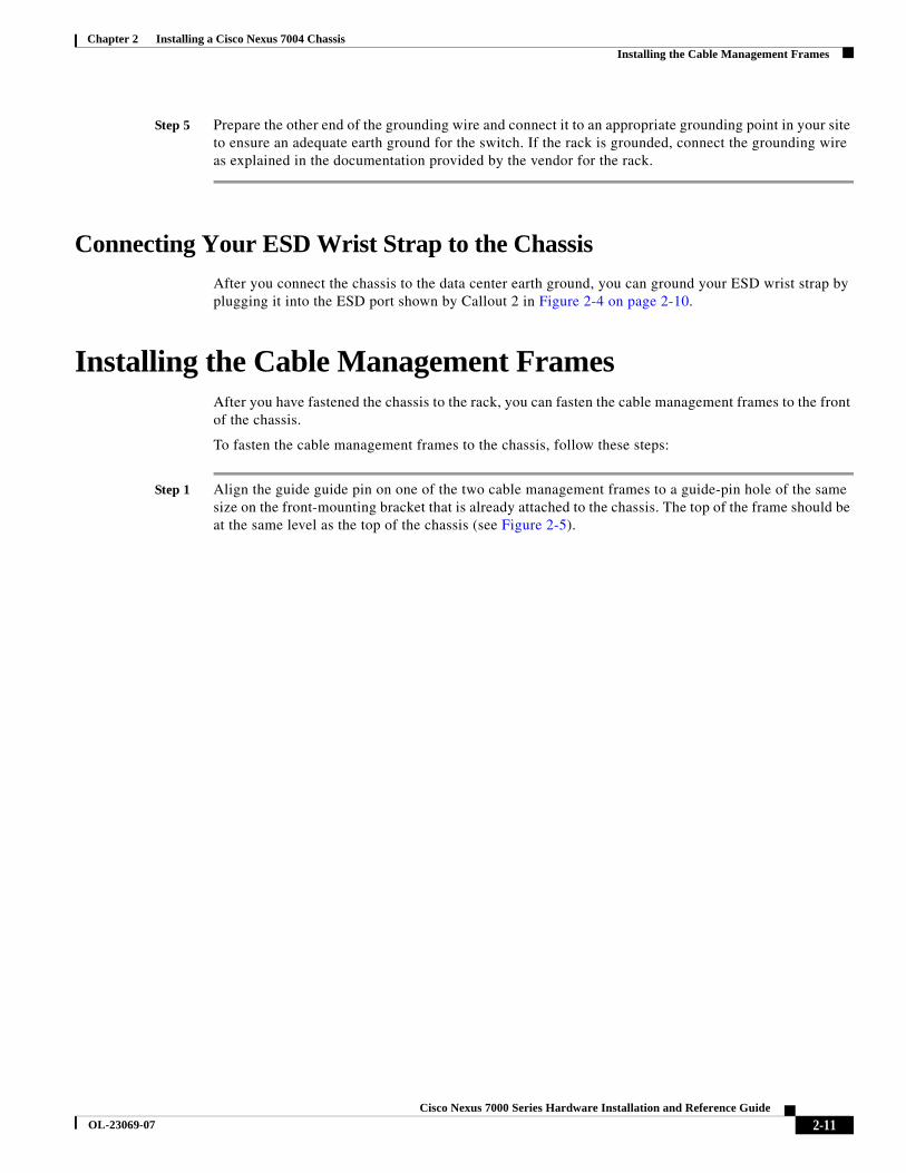
Step 5 Prepare the other end of the grounding wire and connect it to an appropriate grounding point in your site to ensure an adequate earth ground for the switch. If the rack is grounded, connect the grounding wire as explained in the documentation provided by the vendor for the rack.
Connecting Your ESD Wrist Strap to the Chassis
After you connect the chassis to the data center earth ground, you can ground your ESD wrist strap by plugging it into the ESD port shown by Callout 2 in Figure 2-4 on page 2-10.
Installing the Cable Management FramesAfter you have fastened the chassis to the rack, you can fasten the cable management frames to the front of the chassis.
To fasten the cable management frames to the chassis, follow these steps:
Step 1 Align the guide guide pin on one of the two cable management frames to a guide-pin hole of the same size on the front-mounting bracket that is already attached to the chassis. The top of the frame should be at the same level as the top of the chassis (see Figure 2-5).

2-12Cisco Nexus 7000 Series Hardware Installation and Reference Guide
OL-23069-07
Chapter 2 Installing a Cisco Nexus 7004 ChassisInstalling USB Storage Media in a Supervisor 2 or 2E Module
Figure 2-5 Installing the Cable Management Frames on a Cisco Nexus 7004 Chassis
Step 2 Fasten the frame to the chassis with three M3 x 10 mm screws (see Callout 2 in Figure 2-5). Tighten the screws to 5 to 7 in-lb (0.56 to 0.79 N.m).
Step 3 Repeat Steps 1 and 2 to install the other cable management frame to the chassis.
Installing USB Storage Media in a Supervisor 2 or 2E Module
Each Supervisor 2 or 2E module on a Cisco Nexus 7004 switch has a USB drive installed in the LOG FLASH reader. The Slot0 port is left empty, but you can optionally install a USB drive in the that port. To allow this storage media to function with the USB port, you must make sure that it is either already formatted for the port before installing it or format it after installing it.
3347
04
12
12
1 Guide pins on the cable management frame aligned to two holes in the front-mount bracket.
2 Three M3 x 10 mm screws used to fasten the frame to the chassis (total of six screws for two frames).

2-13Cisco Nexus 7000 Series Hardware Installation and Reference Guide
OL-23069-07
Chapter 2 Installing a Cisco Nexus 7004 ChassisInstalling the Air Filter
Note The LOG FLASH and Slot0 USB ports use different formats for their data.
To install storage media in a supervisor module, follow these steps:
Step 1 Insert the USB drive in the LOG FLASH or SLOT0 port.
Step 2 Wait for the reader or port LED to turn green and for a message to appear on the console as follows:
• If you are installing a USB drive into the log flash reader, the message will end with “logflash:online.”
• If you are installing a USB drive into the expansion flash reader, the message will end with “slot0:online.”
• If you see an “offline” message or do not see a message, either the USB drive is not fully inserted or it is improperly formatted.
Make sure that the USB drive is fully inserted inside the reader. If it is fully inserted, either format the card (see the Cisco Nexus 7000 Series NX-OS Fundamentals Configuration Guide) or replace the USB drive with another that is properly formatted for the reader.
Installing the Air FilterThe Cisco Nexus 7004 air filter is an optional feature (part number N7K-C7004-FAN=). To install an air filter, follow these steps:
Step 1 Place the air filter over the air intake area on the right side of the chassis and align the eight screw holes in the filter to screw holes in the chassis.
Step 2 Fasten the air filter to the chassis using eight M3 x 5 mm screws that came with the air filter.. Tighten the screws to 5 to 7 in-lb (0.56 to 0.79 N.m).

2-14Cisco Nexus 7000 Series Hardware Installation and Reference Guide
OL-23069-07
Chapter 2 Installing a Cisco Nexus 7004 ChassisInstalling the Air Filter


![Dnevni avaz [broj 7004, 6.2.2015]](https://img.dokumen.tips/doc/110x75/577cbfdd1a28aba7118e4e83/dnevni-avaz-broj-7004-622015.jpg)
