Embed Size (px)
DESCRIPTION
Presentation is an outline of the process and stages involved in preparing a Detailed Project Report (DPR) for Road and Highway Projects
Citation preview
Preparation of Detailed Project Report (DPR)
Presentation on
Preparation of Detailed Project Report (DPR) for Road Projects
By
Rathnakara Reddy KBManaging Director
Infra Support Engineering Consultants Pvt. Ltd.Bangalore
May 14, 2012, Bangalore
Preparation of Detailed Project Report (DPR)
1.0 Understanding Scope of Work2.0 Traffic Surveys 3.0 Engineering Investigations 4.0 Detailed Designs5.0 Tender and Construction Drawings6.0 Project Costing 7.0 Economic Analysis 8.0 Formulation of Construction Packages 9.0 Compiling Project Report
Preparation of DPR involves following components

Preparation of Detailed Project Report (DPR)
UNDERSTANDING THE TOR• First and foremost thing is to study carefully and understand the Terms of
Reference (ToR) or Scope of Services of the project.• Once the ToR is understood, the conceptualization of the project would be
easy.• Mostly the ToR for a particular type of projects remains same across any
organization.– Duration of the Project, Phases (Feasibility, PPR, DPR) and Reporting requirements– Proposals for improvements, if any, (type of cross section, grade separators, major
Bridges, Bypasses etc.)– Any special types of Surveys and project specific considerations– Requirements for Economic and Financial Analysis,– Issues on Right of Way (RoW) and Land Acquisition– Social and Environmental surveys
Scope of Services
Preparation of Detailed Project Report (DPR)
SURVEYS AND INVESTIGATIONS
1. Reconnaissance Survey2. Traffic Surveys3. Topographic Surveys 4. Engineering Surveys 5. Soil & Material Investigations 6. Social And Environmental Surveys
Preparation of Detailed Project Report (DPR)
Traffic Surveys• The initial task of identifying the homogeneous traffic links shall be undertaken on
the identified road sections• homogeneous traffic links will be established through identification of the major
intersections and urban centres. • The fixation of locations will be made for traffic volume surveys, both at mid
sections and intersections
• Traffic Volume Surveys • O-D And Commodity Surveys • Turning Movement Surveys • Parking Surveys • Speed And Delay Surveys • Cross Pedestrian And Animal Surveys • Axle Load Surveys • Truck Terminal Surveys • Willingness to pay Surveys
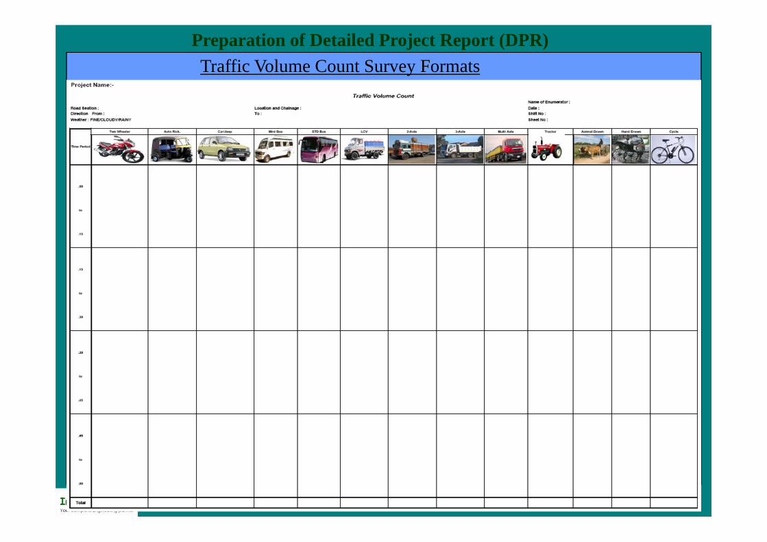
Preparation of Detailed Project Report (DPR)Traffic Volume Count Survey Formats
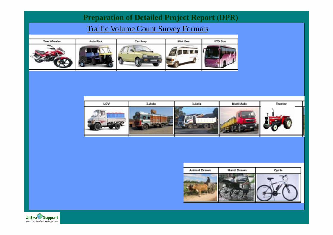
Preparation of Detailed Project Report (DPR)Traffic Volume Count Survey Formats

Preparation of Detailed Project Report (DPR)

Preparation of Detailed Project Report (DPR)

Preparation of Detailed Project Report (DPR)
TRFFIC FORECASTING• Traffic volume count survey gives ADT• ADT is to be converted to AADT based on seasonal variation factors• seasonal variation factors can be obtained by fuel consumption rates or past trafic
data• AADT thus obtained shall be used as base year traffic• Traffic is to be forecasted for at least next 10 years• Traffic Growth rates can be obtained using
– Trend Analysis– Econometric Model
– A more rational method will be to establish a relationship between the socio-economic variables such as Population, Net State Domestic Product (NSDP) and Per-Capita Income (PCI) on the one hand and the past registration data of different categories of vehicles on the other to determine the elasticity of transport demand with respect to different categories of vehicles. According to IRC: 108 - 1996, an econometric model should be derived
Preparation of Detailed Project Report (DPR)
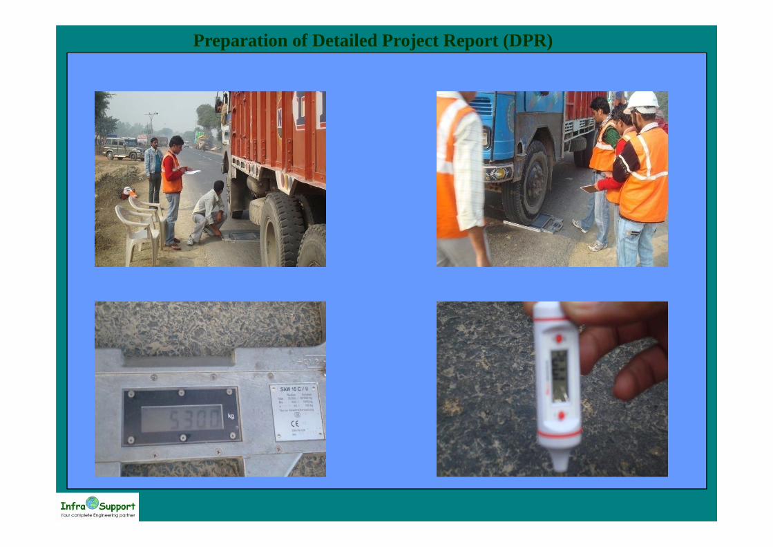
Axle Load Surveys• Traffic loading has a significant impact on pavement performance and design. • damage that vehicles create to a road depends very strongly on the axle loads of the
vehicles. • The exact relationship is influenced by the type of road structure and the way the
road deteriorates but a `fourth power’ damage law gives a good approximation.
– Measurements will be made for two days over a 24-hour period on random sampling basis. – analyse the axle load survey data to bring out the Gross Vehicle Weight (GVW) and Single Axle Load
(SAL) distributions by truck type and axle configuration.
Preparation of Detailed Project Report (DPR)

Preparation of Detailed Project Report (DPR)
AXLE LOAD SURVEY CALCULATIONS
Section : Date & Time31/01/2011
Location : Chainage :
Direction : Type : 2 -Axle
Direction Type*
Wheel Load (Tonnes)ESWL Individual VDF
VDFAxle
1st 2nd 3rd 4th 5th FW RW FW RW
DIR_01 2 1.9 1.75 0 0 0 0.4657 0.4289 0.05 0.03 0.08
DIR_01 2 1.8 4 0 0 0 0.4412 0.9804 0.04 0.92 0.96
DIR_01 2 2.6 6 0 0 0 0.6373 1.4706 0.16 4.68 4.84
DIR_01 2 2.2 1.95 0 0 0 0.5392 0.4779 0.08 0.05 0.14
DIR_01 2 1.8 1.5 0 0 0 0.4412 0.3676 0.04 0.02 0.06
DIR_01 2 1.8 4 0 0 0 0.4412 0.9804 0.04 0.92 0.96
DIR_01 2 1.8 2 0 0 0 0.4412 0.4902 0.04 0.06 0.10

Preparation of Detailed Project Report (DPR)
Direction Type*
Multi Axle VehicleWheel Load (Tonnes)
ESWL Individual VDFVDFAxle
1st 2nd 3rd 4th 5th 6th FW RW1 RW2 RW3 FW RW1 RW2 RW3
DIR_01 4 2.2 1.9 1.45 1.6 0 0 0.539 0.466 0.408 0.000 0.085 0.047 0.028 0.000 0.16
DIR_01 4 2.9 5.7 6.3 4.2 0 0 0.711 1.397 1.403 0.000 0.255 3.809 3.875 0.000 7.94
DIR_01 4 1.7 2.95 4.1 4.9 0 0 0.417 0.723 1.203 0.000 0.030 0.273 2.091 0.000 2.39
DIR_01 4 1.8 4.75 5.1 5.15 0 0 0.441 1.164 1.370 0.000 0.038 1.837 3.519 0.000 5.39
DIR_01 4 2.3 1.8 1.45 1.5 0 0 0.564 0.441 0.394 0.000 0.101 0.038 0.024 0.000 0.16
DIR_01 4 2.15 4.35 1.55 3.65 0 0 0.527 1.066 0.695 0.000 0.077 1.292 0.233 0.000 1.60
DIR_01 4 1.9 4.5 5.6 4.55 0 0 0.466 1.103 1.356 0.000 0.047 1.480 3.383 0.000 4.91
DIR_01 4 3 5.2 5.6 4.5 0 0 0.735 1.275 1.350 0.000 0.292 2.639 3.317 0.000 6.25
DIR_01 4 2.1 6.2 6.45 6.85 0 0 0.515 1.520 1.777 0.000 0.070 5.332 9.974 0.000 15.38
DIR_01 4 2.5 3.2 5.6 5 0 0 0.613 0.784 1.416 0.000 0.141 0.378 4.024 0.000 4.54
DIR_01 4 2.8 5.65 6.2 4.2 0 0 0.686 1.385 1.390 0.000 0.222 3.678 3.729 0.000 7.63
DIR_01 4 2.8 4 5.5 4 0 0 0.686 0.980 1.269 0.000 0.222 0.924 2.596 0.000 3.74
DIR_01 4 2.1 4.5 2.05 3.6 0 0 0.515 1.103 0.755 0.000 0.070 1.480 0.325 0.000 1.87

Preparation of Detailed Project Report (DPR)
Vehicle Type
VDFLHS RHS AVG
LCV 0.08 0.13 0.102 Axle 2.90 1.10 2.003 Axle 4.85 3.24 4.04M A 7.27 9.89 8.58
VDF CALCULATIONS

Preparation of Detailed Project Report (DPR)
Engineering Surveys And Investigation Road Inventory Survey Inventory And Condition Assessment Of Existing Cross Drainage Structures Preparation Of Strip Plan Assess Adequacy Of Drainage Pavement Condition Survey Pavement Roughness Survey Pavement Composition Survey Benkelman Beam Deflection (Bbd) Survey

Preparation of Detailed Project Report (DPR)
Road Inventory Survey• The Road Inventory survey consists of recording the physical features along and
across the project road in a prescribed format. – Average width of pavement, shoulders and formation – Surface type of carriageway and shoulders– Right of Way (ROW)– Average embankment, height, type and condition – Location of major Bridges, RoBs, Flyovers.– Type and location of Side Drains– Road Side Land Use– Utility lines and trees within the boundaries– Location and Condition of Traffic Sign Boards– Location of Bus stops, Parking areas and other amenities– Location of Major industries and business centers – Location and details of cross roads– Sight distance details– Perched water table, HFL, Depth of submergence the road is subject to– Areas subject to chronic flooding and submergence– Recording urban and Rural areas, name of places and settlements

Preparation of Detailed Project Report (DPR)ROAD INVENTORY SURVEY
Name of the road: Date:
Direction:
Chainage(km) Carriageway Shoulder Width(M)
Terrain type
Ht. Of Fill/cut (m)
Land use
Soil type
Geometrics
Major Jn.Enroute villages
Drainage RemarksFrom To
Width(M) Type Left Right Type Left Right
extent of slope
erosion Horizontal Vertical
0 1 3.75 SDBC 1.7P,1.1E 1.1B Plain 2 - No Erosion AgriculturalSilty-Clay LC - SH - OK
1 2 3.75 SDBC 1.0B,1.0E 1.0B,1.0E Plain 1.5 1.5 No Erosion AgriculturalSilty-Clay valley - OK
2 2.5 3.75 SDBC 1.0B,1.0E 1.0B,1.0E Plain 1.5 No Erosion IndustrialSilty-Clay SC - - OK
2.5 3 3.75 SDBC 1.0B,1.0E 1.0B,1.0E Plain 1.3 1.5 No Erosion AgriculturalSilty-Clay - ABC OK
3 3.2 3.75 SDBC 1.0B,1.0E 1.0B,1.0E Plain 1.2 1.3 No Erosion AgriculturalSilty-Clay Poor

Preparation of Detailed Project Report (DPR)
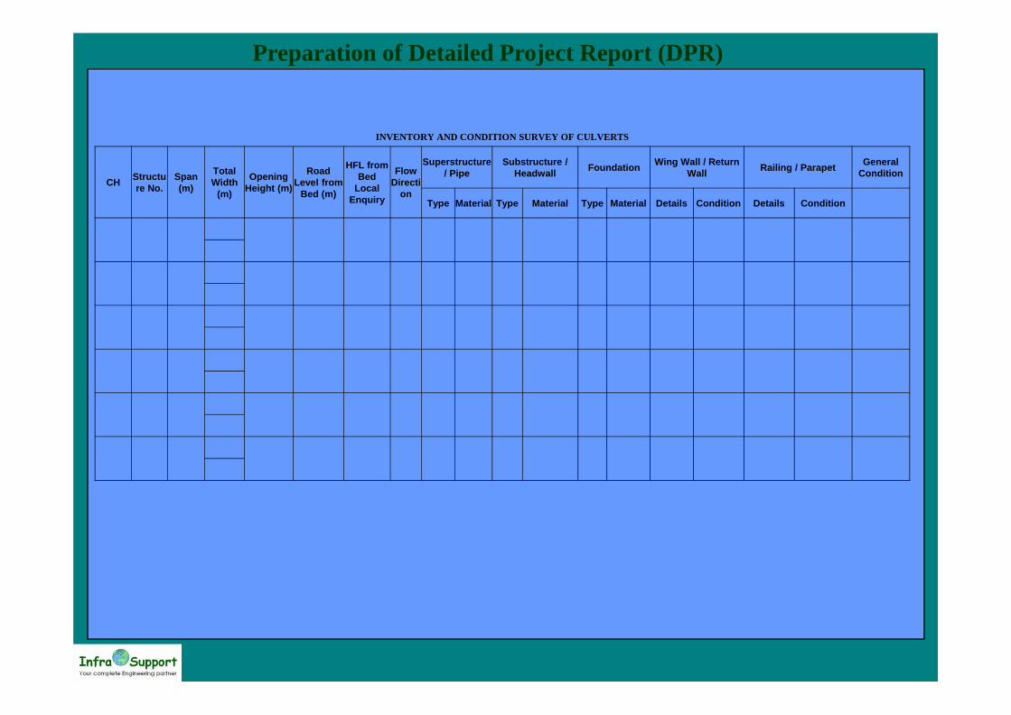
Inventory and Condition Assessment of Existing Cross Drainage Structures• The location of each bridge and culvert shall be recorded, along with its type and
the carriageway width.• A detailed inspection of bridges and culverts shall be carried out to assess their
condition. This would lead to a report preparation on condition of bridges andstructures.
• The structures, which show deficiency in terms of capacity and strength, shall bereviewed in the light of repair/rehabilitation possibilities with suitablerecommendations.
Preparation of Detailed Project Report (DPR)
INVENTORY AND CONDITION SURVEY OF CULVERTS
CH Structure No.
Span (m)
Total Width
(m)
Opening Height (m)
Road Level from
Bed (m)
HFL from Bed
Local Enquiry
Flow Directi
on
Superstructure / Pipe
Substructure / Headwall Foundation Wing Wall / Return
Wall Railing / Parapet General Condition
Type Material Type Material Type Material Details Condition Details Condition
Preparation of Detailed Project Report (DPR)
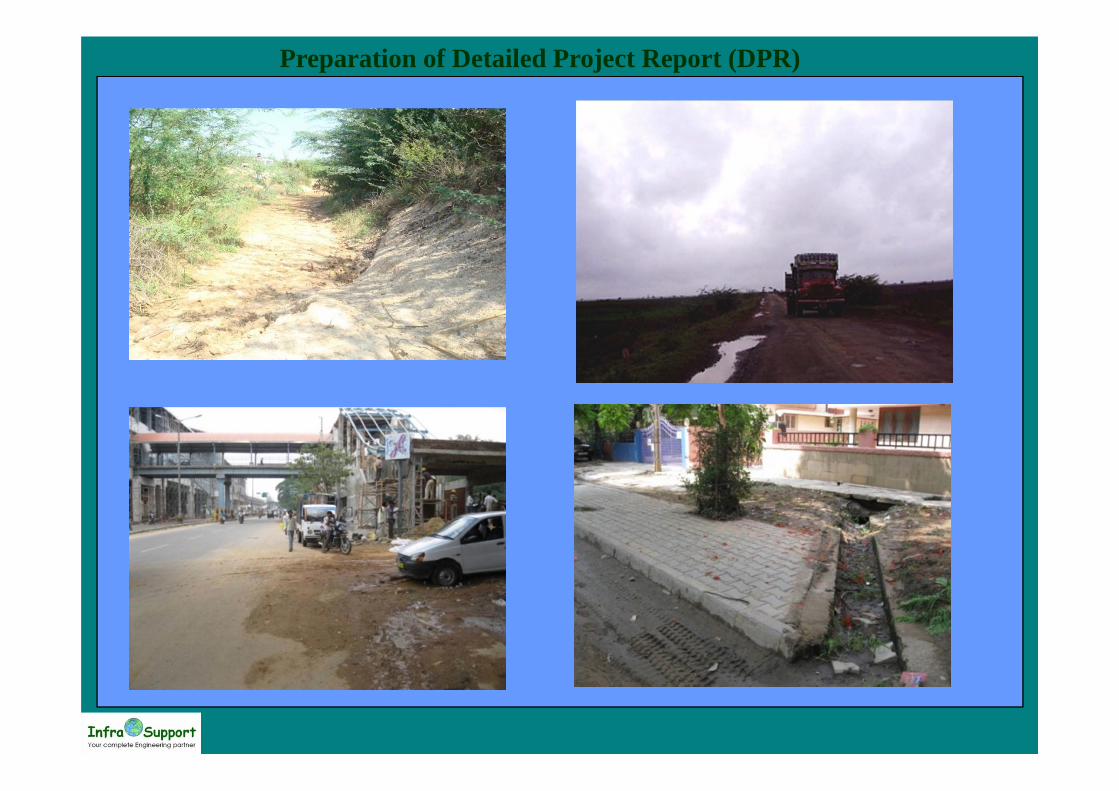
Assess Adequacy of Drainage• Inadequacy of drainage reflects in terms of fast deterioration of the pavement as
well as causes inconvenience to the traffic,– General condition of drainage– Connectivity of drainage turnouts en-route into the network topography– Condition in cut sections– Condition at embankments
Preparation of Detailed Project Report (DPR)
Preparation of Detailed Project Report (DPR)
Pavement Condition Survey• Detailed field studies shall be carried out to assess the adequacy and effectiveness
of the existing pavement. The data Shall generally cover– Pavement condition (surface distress type and extent)– Shoulder condition– Embankment condition– Drainage condition

Preparation of Detailed Project Report (DPR)
PAVEMENT CONDITION SURVEYName of Road: Date:Direction:
Chainage(KM) Cracking % areaPotholes
Area%Patching
Area%Ravelling
Area%
Edge Break
%length
Unpaved Shoulder
RemarksFrom ToNarrow<3mm
Wide>3mm
Dropoff(mm)
Depression(mm)
Material loss(M^3)

Preparation of Detailed Project Report (DPR)

Preparation of Detailed Project Report (DPR)
Pavement Roughness Survey• Roughness is a critical attribute for modeling the economic variables of investment.
The roughness is measured in International Roughness Index (IRI), the unit of IRIis m/km.
• The roughness surveys shall be conducted using a fifth wheel Bump Integrator(preferably vehicle equipped with ROMDAS).
• The test vehicle shall be run on the wheel path on both the directions preferablythree times and the average result is reported as the IRI.
Kilometerwise IRI
0.001.002.003.004.005.006.007.008.00
52 56 60 64 68 72 76 80 84 88 92 96 100 104 108 112 116 120 124 128 132 136 140 144 148
Chainage
IRI

Preparation of Detailed Project Report (DPR)
Percentage distribution of IRI
IRI 2.5-50%
IRI 5-845%
IRI 8-1048%
IRI >=107%
Chainage
Roughness (IRI)
Section Avg.
Roughness (IRI)From To
1 2 4.5
…..2 3 5.14
3 4 4.08
4 5 5.26
Summary
Percentage Distribution of IRI
Preparation of Detailed Project Report (DPR)
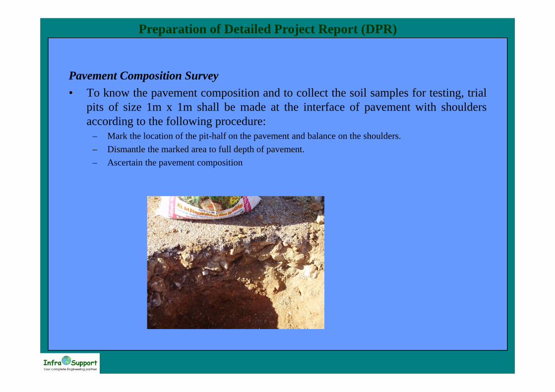
Pavement Composition Survey• To know the pavement composition and to collect the soil samples for testing, trial
pits of size 1m x 1m shall be made at the interface of pavement with shouldersaccording to the following procedure:
– Mark the location of the pit-half on the pavement and balance on the shoulders.– Dismantle the marked area to full depth of pavement.– Ascertain the pavement composition
Preparation of Detailed Project Report (DPR)
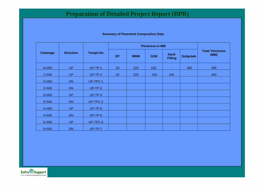
Summary of Pavement Composition Data
Chainage Direction Testpit No
Thickness in MMTotal Thickness
(MM)BT WBM GSB SandFilling Subgrade
0+250 UP UP-TP-1 20 225 150 - 300 395
1+500 UP UP-TP-2 25 225 150 100 - 400
2+000 DN UP-TPC-1
2+500 DN UP-TP-3
3+000 UP UP-TP-4
3+500 DN UP-TPC-2
4+000 UP UP-TP-5
4+500 DN UP-TP-6
5+000 UP UP-TPC-3
5+500 DN UP-TP-7
Preparation of Detailed Project Report (DPR)
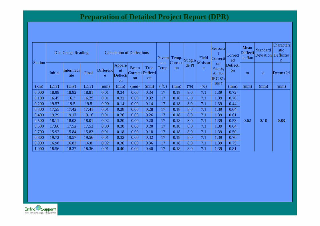
Benkelman Beam Deflection (BBD) Survey• The procedure for carrying out BBD survey shall be in conformity with IRC:81-
1997. Deflections are measured at 50m intervals staggered on both directions oftraffic and then apply the method of cumulative differences to divide the sectionsfor arriving at the characteristic deflections.
– Traffic regulation arrangement during carrying out Benkelman Beam Deflection surveys shall be asfollows
– Cordon the area with suitably spaced cones and provide temporary traffic signs.– Carryout the Benkelman Beam survey work.– Shift the cones and temporary signs to next location.

Preparation of Detailed Project Report (DPR)
Preparation of Detailed Project Report (DPR)
Station
Dial Gauge Reading Calculation of DeflectionsPavem
ent Temp.
Temp. Correcti
on
Subgrade PI
Field Moistur
e
Seasonal
Correction
Factor, As Per
IRC 81: 1997
Corrected
Deflection
Mean Deflection /km
Standard Deviation
Characteristic
Deflection
Initial Intermediate Final Differenc
e
Apparent
Deflection
Beam Correcti
on
True Deflecti
onm d Dc=m+2d
(km) (Div) (Div) (Div) (mm) (mm) (mm) (mm) (OC) (mm) (%) (%) (mm) (mm) (mm) (mm)0.000 18.98 18.82 18.81 0.01 0.34 0.00 0.34 17 0.18 8.0 7.1 1.39 0.72
0.62 0.10 0.83
0.100 16.45 16.3 16.29 0.01 0.32 0.00 0.32 17 0.18 8.0 7.1 1.39 0.700.200 19.57 19.5 19.5 0.00 0.14 0.00 0.14 17 0.18 8.0 7.1 1.39 0.440.300 17.55 17.42 17.41 0.01 0.28 0.00 0.28 17 0.18 8.0 7.1 1.39 0.640.400 19.29 19.17 19.16 0.01 0.26 0.00 0.26 17 0.18 8.0 7.1 1.39 0.610.500 18.11 18.03 18.01 0.02 0.20 0.00 0.20 17 0.18 8.0 7.1 1.39 0.530.600 17.66 17.52 17.52 0.00 0.28 0.00 0.28 17 0.18 8.0 7.1 1.39 0.640.700 15.92 15.84 15.83 0.01 0.18 0.00 0.18 17 0.18 8.0 7.1 1.39 0.500.800 19.72 19.57 19.56 0.01 0.32 0.00 0.32 17 0.18 8.0 7.1 1.39 0.700.900 16.98 16.82 16.8 0.02 0.36 0.00 0.36 17 0.18 8.0 7.1 1.39 0.751.000 18.56 18.37 18.36 0.01 0.40 0.00 0.40 17 0.18 8.0 7.1 1.39 0.81

Preparation of Detailed Project Report (DPR)
The summary of Benkelman Beam Deflection data is as follows
Preparation of Detailed Project Report (DPR)
Material Investigations
Existing Sub-Grade And Embankment Soils Construction Materials Investigation Borrow Areas Quarries For AggregatesQuarries For Sand Sources For Other Construction Materials
Preparation of Detailed Project Report (DPR)
Material Investigations• Material investigation aims at collecting all material samples that is being used
under the present road and anticipated borrow material and subject to standardtesting procedure to recommend most appropriate designs
– Soil sampling, field density tests and laboratory tests on existing sub-grade and soil sampling ofembankment soils.
– Investigating borrow materials for embankment, sub-grade and granular sub-base.– Investigating aggregate and sand quarries– Locating water sources for construction work– Identifying sources for other construction material such as cement, bitumen and steel.– Samples of borrow soils, sand, crushed rock and gravel for use in embankment, and pavement
structure.

Preparation of Detailed Project Report (DPR)
Material Quarry Map

Preparation of Detailed Project Report (DPR)
• Subgrade Soil Samples– The tests being performed are– Grain size distribution test for each sample,– Atterberg limits for each sample,– Moisture density relationship (Heavy Compaction) for each sample,– Unsoaked CBR tests at optimum moisture content at three energy levels.– Four days soaked CBR at three energy levels on each homogenous group of soils. Soaked CBR at
FDD and 97% of the MDD is to be determined from the graphs plotted for CBR vs Density at threeenergy levels.

Preparation of Detailed Project Report (DPR)
Type of Test MethodField dry density using sand replacement method
IS 2720 Part 28
Field dry density using core cutter method IS 2720 Part 29Moisture content determination IS 2720 Part 2 (section I)Atterberg limits IS 2720 Part 5Sieve analysis
- natural soils- rock aggregate
IS 2720 Part 4IS 2386 Part 1
Compaction test (Heavy Compaction) IS 2720 Part 8CBR and Swell(Soaked and unsoaked at three energy levels for sub-grade)
IS 2720 Part 16
Aggregate impact value IS 2386 Part 4Coating and stripping of Bitumen aggregate mixtures IS 6241
Soundness of Aggregates IS 2386 Part 5Flakiness and Elongation Index IS 2386 Part 1Water Absorption and Specific Gravity of aggregate IS 2386 Part 3
Stone Polishing Value BS 812 Part 11410 % Fines Value for Aggregate BS 812 Part 111
Testing Codes Adopted
Preparation of Detailed Project Report (DPR)
Topographic Surveys• Topographical survey is the backbone of detailed engineering design.• Accuracy of the information collected during this survey has direct bearing on
almost all the design activities involved in project preparation.• The beginning of topographical surveys is made with collection of preliminary
information of latitude and longitude of the region as well as approximate reducedlevel above mean sea from Survey of India maps available in the region
– Setting up permanent bench marks and control stations to be used during construction– Establishment of horizontal control with GPS to have unique coordinate system of northing and
easting along the project corridor– Establishment of vertical control to have the elevation coordinate hooked to nearest GTS stations
along the project corridor– Collection of Digital Terrain Model data containing the existing highway, rivers, streams and other
topographical features to form the basis for the new designs;– Preparation of base plans containing the entire natural and man made features like buildings, fences,
walls, utilities, temples and other religious structures etc. that would govern the finalisation ofhorizontal alignment.

Preparation of Detailed Project Report (DPR)
X
X
XX
X
X X
EPL01
EPR01
CLV01
X
CLV01
CLV01CLV01
CLV02CLV02
CLV02 CLV02
EPL01
EPR01
BG02
BG02
BG02
BG02
BG01
BG01
BG01
BG01
• Coding for various types of features is comprised of four characters.• The first two characters describe the type of feature and the last two characters
indicate the string number.• The string number i.e. the last two characters are alphanumeric, such as, A1-A9, BO-
B9.......... ZO- Z9, AA-AZ, BA-BZ, .…….. ZA- ZZ.
Preparation of Detailed Project Report (DPR)
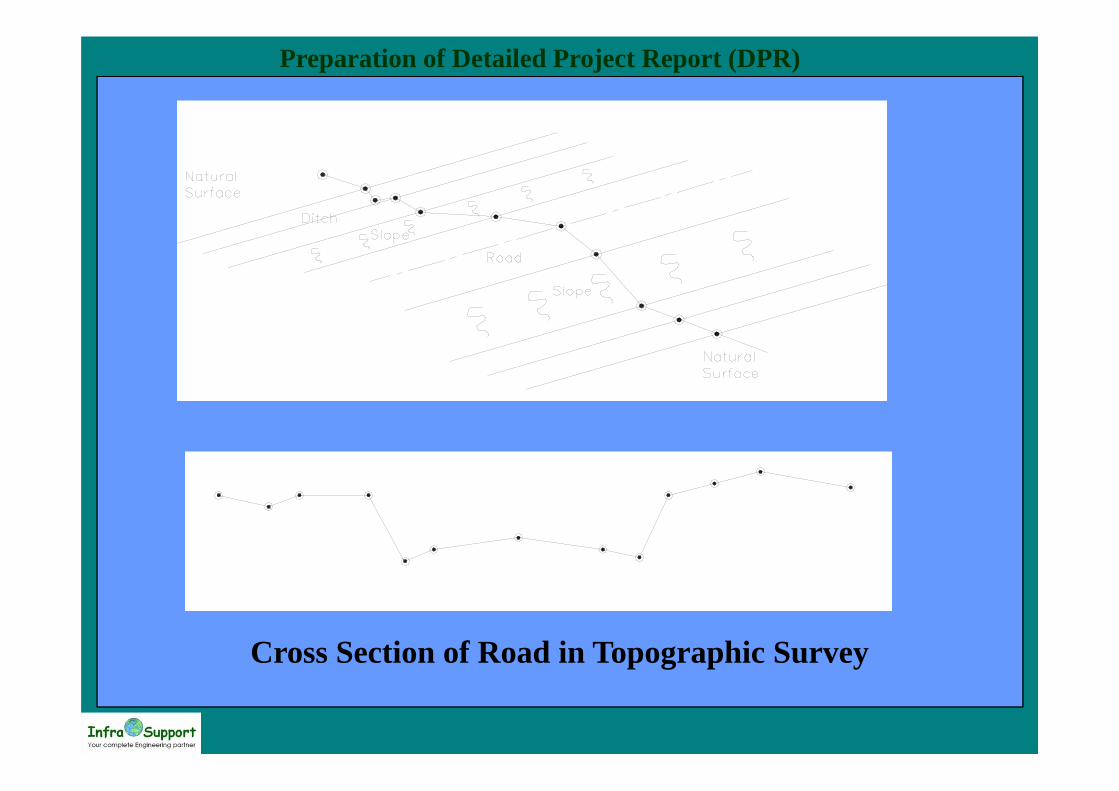
Cross Sections
• With a view to obtain an accurate surface cross section on the pavementshall be collected at 25 m intervals at the tangent sections and 10-25m incurve sections.
• The cross-sections levels were taken on the embankment profile or groundas necessary to define ground profile, properly.
• Center line of carriageway (Code CC**);• Edge of carriageway (Code CE**);• Paved shoulder (Code SH**). This is where the seal has been extended past the
normal edge of the road to include a part of the shoulder;• Edge of shoulder (Code SS**); Where ** indicates left or right string• Point on undisturbed original ground level (OG);• Point on partially or completely filled surface of the top of embankment/ formation
(ET**)• Point on bottom of embankment (EB**); Where ** indicates left or right string
Preparation of Detailed Project Report (DPR)
Cross Section of Road in Topographic Survey
Preparation of Detailed Project Report (DPR)
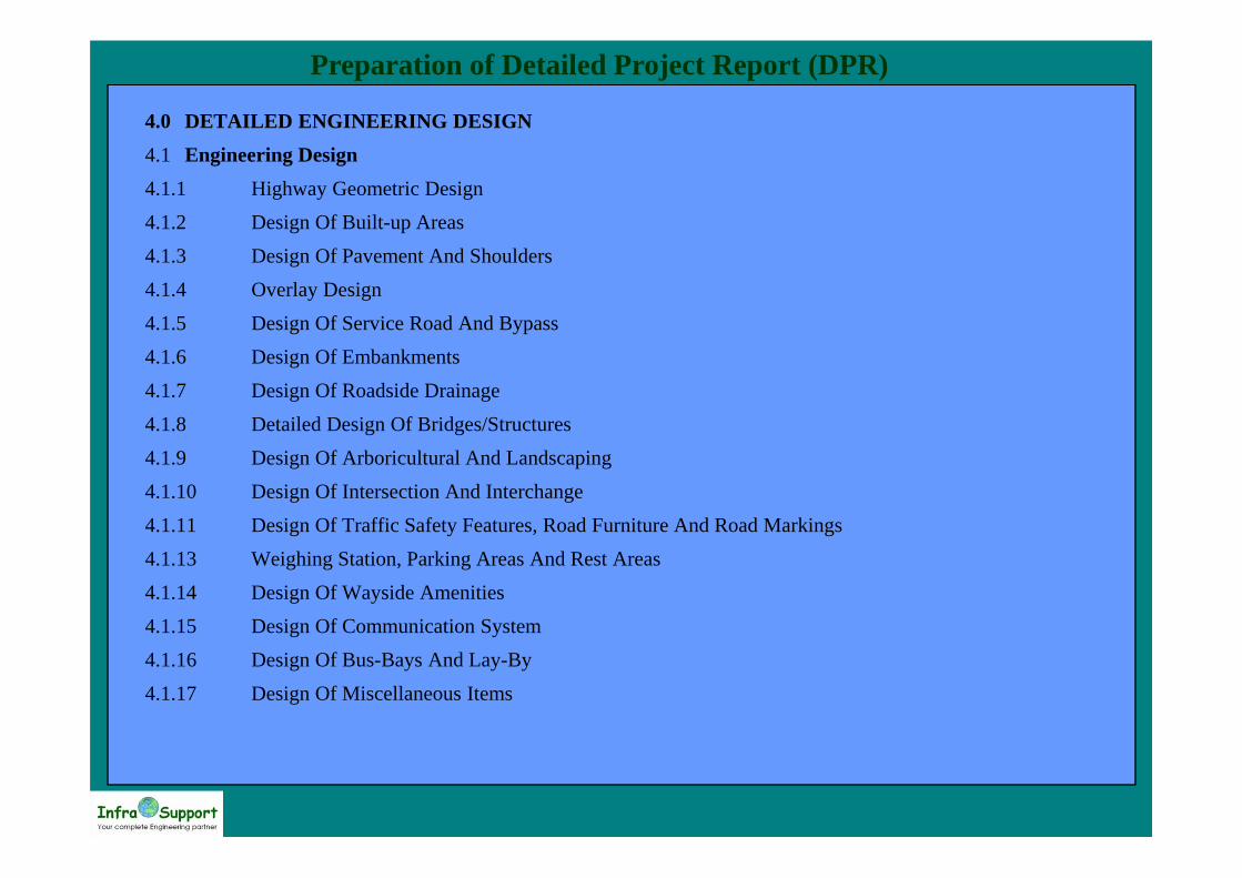
4.0 DETAILED ENGINEERING DESIGN 4.1 Engineering Design 4.1.1 Highway Geometric Design 4.1.2 Design Of Built-up Areas 4.1.3 Design Of Pavement And Shoulders 4.1.4 Overlay Design 4.1.5 Design Of Service Road And Bypass 4.1.6 Design Of Embankments 4.1.7 Design Of Roadside Drainage 4.1.8 Detailed Design Of Bridges/Structures 4.1.9 Design Of Arboricultural And Landscaping 4.1.10 Design Of Intersection And Interchange 4.1.11 Design Of Traffic Safety Features, Road Furniture And Road Markings 4.1.13 Weighing Station, Parking Areas And Rest Areas 4.1.14 Design Of Wayside Amenities 4.1.15 Design Of Communication System 4.1.16 Design Of Bus-Bays And Lay-By 4.1.17 Design Of Miscellaneous Items
Preparation of Detailed Project Report (DPR)
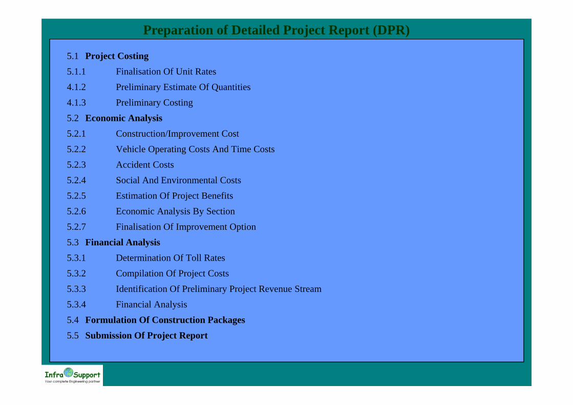
5.1 Project Costing 5.1.1 Finalisation Of Unit Rates 4.1.2 Preliminary Estimate Of Quantities 4.1.3 Preliminary Costing 5.2 Economic Analysis 5.2.1 Construction/Improvement Cost 5.2.2 Vehicle Operating Costs And Time Costs 5.2.3 Accident Costs 5.2.4 Social And Environmental Costs 5.2.5 Estimation Of Project Benefits 5.2.6 Economic Analysis By Section 5.2.7 Finalisation Of Improvement Option 5.3 Financial Analysis 5.3.1 Determination Of Toll Rates 5.3.2 Compilation Of Project Costs 5.3.3 Identification Of Preliminary Project Revenue Stream 5.3.4 Financial Analysis 5.4 Formulation Of Construction Packages 5.5 Submission Of Project Report

Preparation of Detailed Project Report (DPR)
Highway Geometric Design• Horizontal Alignment: The proposed centerline shall be finalised using a
sophisticated highway design software, All the curves having poor geometry shallbe improved to the acceptable design standards
Preparation of Detailed Project Report (DPR)
• Vertical Profile: The existing longitudinal section of the project road shall beobtained from modeling the ground data. The finished profile shall depend on thethickness of the pavement layer determined from pavement design provision fornecessary profile corrective and camber corrective course.
– Avoid cutting/scraping of existing pavement at strengthening only sections– Compatibility of design speed to horizontal geometry of the section– Provide adequate vertical curve at the grade change from stopping sight distance criterion.
Preparation of Detailed Project Report (DPR)
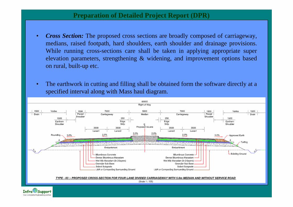
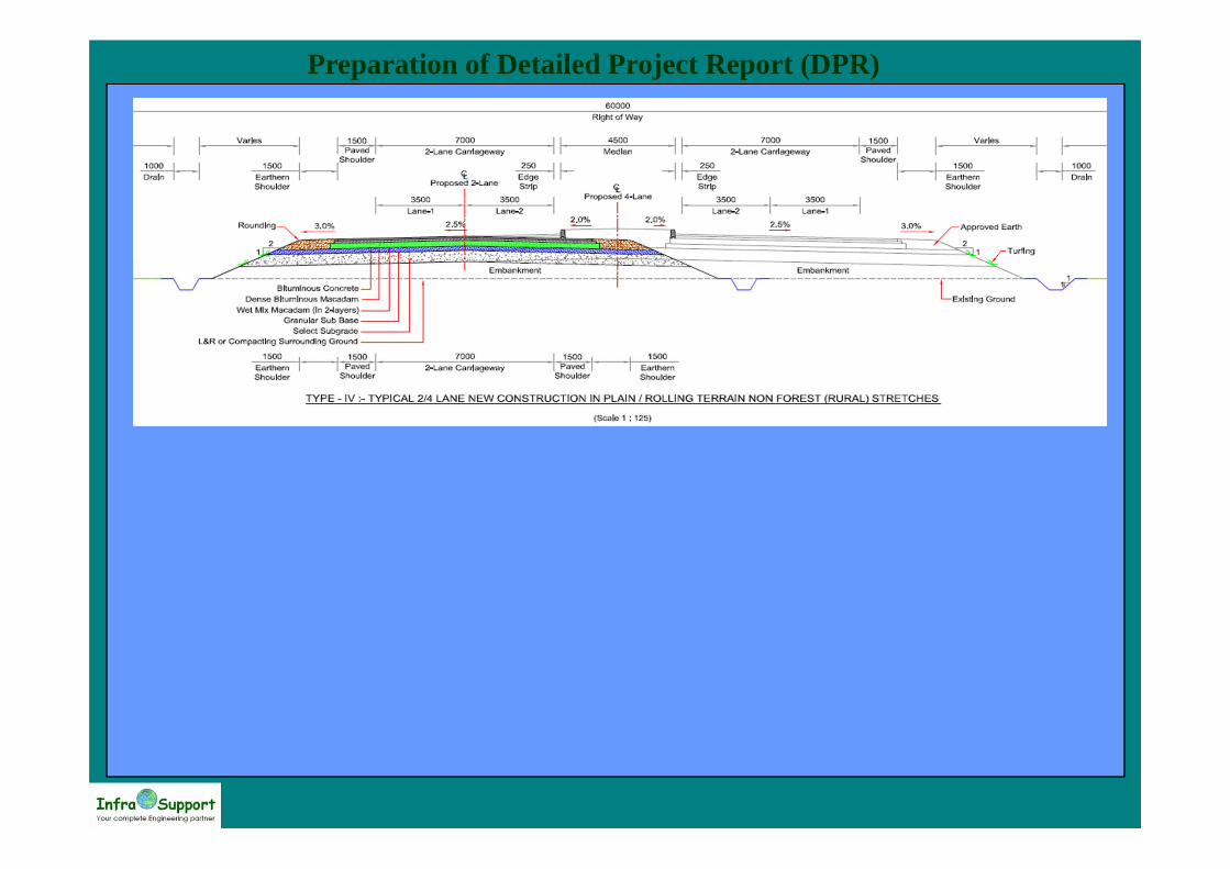
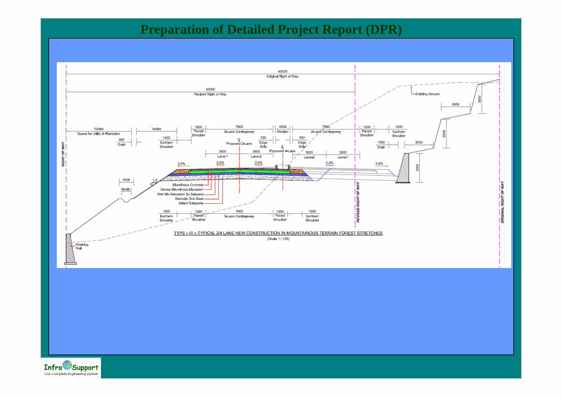
• Cross Section: The proposed cross sections are broadly composed of carriageway,medians, raised footpath, hard shoulders, earth shoulder and drainage provisions.While running cross-sections care shall be taken in applying appropriate superelevation parameters, strengthening & widening, and improvement options basedon rural, built-up etc.
• The earthwork in cutting and filling shall be obtained form the software directly at aspecified interval along with Mass haul diagram.
Preparation of Detailed Project Report (DPR)
Preparation of Detailed Project Report (DPR)

Preparation of Detailed Project Report (DPR)
Design of Built-upAreas• This activity shall focus on design of urban areas in the form of parking lane,
service road, sidewalk and roadside drainage underneath the sidewalk etc. All thesedetails shall be clearly shown in the horizontal plan and also typical cross sectionsshall be prepared.
Design of Pavement and ShouldersOverlay Design• The performance of pavement in terms of functional performance, structural
performance, structural capacity, and safety contribute to the need for an overlay.• Functional performance refers to the ability of the pavement surface to provide a
reasonable riding quality measured in terms of roughness.• Structural performance is the ability to retain the integrity of the pavement by
preventing distress in the form of cracks, ruts, potholes, etc.• Structural capacity is the pavement's ability to accommodate the axle load on the
pavement. Safety aspect refers mainly the skid resistance and hydroplaningpotential.

Preparation of Detailed Project Report (DPR)
Design of Service Road and Bypass• This activity shall focus on design of service road and bypass in terms of number of
lanes and pavement composition.• The local traffic component shall be segregated and would determine the number of
lanes to be provided in the service road. Depending on this traffic loading and soilinvestigation already carried out, the pavement composition shall be decided.
Design of Embankments• The embankments would be designed after detailed analysis and as per the relevent
standards and latest software available. General design parameters shall follow IRCguidelines.
Design of Roadside Drainage• Drainage is an important aspect in the design of highway. With poor drainage
conditions the pavement will not sustain till the end of design life.– Design of kutcha drain on both sides near RoW limits in rural sections– Covered pucca drains near urban areas if necessary– Design of chutes in high embankment areas for drainage of surface water– In super elevation sections median drains shall be provided– As a slope protection measure for high embankment section, turfing on slopes or pitching shall be
designed as per the design standards.
Preparation of Detailed Project Report (DPR)
Detailed Design of Bridges/Structures• Based on the detailed survey, sub-surface investigation and design standards and
specifications developed bridge/structures shall be designed.• General design parameters and loadings shall follow IRC guidelines, amended
when necessary in consultation with client.• In selecting foundation type, the consultant shall also take into account the time
required for construction of alternatives, and give preference to those whichminimise construction time.
• In developing the standard designs and for those designs, which cannot bestandardized, computer programs for design and drawing shall be used extensively.On the basis of the investigation and design standards, detailed designs for minorbridges and culverts shall be prepared.
• Design of Arboricultural and Landscaping• Appropriate plans shall be developed for planting of trees, horticulture and
floriculture on the unused land of the RoW in order to beautify the project corridorview and improve the overall aesthetics.
Preparation of Detailed Project Report (DPR)
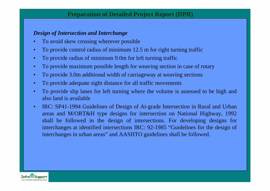
Design of Intersection and Interchange• To avoid skew crossing wherever possible• To provide control radius of minimum 12.5 m for right turning traffic• To provide radius of minimum 9.0m for left turning traffic• To provide maximum possible length for weaving section in case of rotary• To provide 3.0m additional width of carriageway at weaving sections• To provide adequate sight distance for all traffic movements• To provide slip lanes for left turning where the volume is assessed to be high and
also land is available• IRC: SP41-1994 Guidelines of Design of At-grade Intersection in Rural and Urban
areas and M/ORT&H type designs for intersection on National Highway, 1992shall be followed in the design of intersections. For developing designs forinterchanges at identified intersections IRC: 92-1985 “Guidelines for the design ofinterchanges in urban areas” and AASHTO guidelines shall be followed.

Preparation of Detailed Project Report (DPR)
Design of Toll Plaza• Design toll plaza layout based on traffic segregation, acceptable queue length, toll
collection system and the average waiting time shall be made.• The plaza shall be designed based on the forecast traffic in such a way that the
traffic shall be subject to minimum delay and inconvenience. Also necessaryfacilities shall be provided in the design for effective toll collection.
Design of Traffic Safety features, Road Furniture and Road Markings• Design of traffic signs and road markings, to effectively guide and control the
traffic, shall be carried out based on current national and international practices.Weighing Station, Parking Areas and Rest Areas• Sites for Weighing stations, parking areas and rest areas shall be selected based on
the data collected and as per the discussions with the MoRT&H.• Design of Wayside Amenities• Design of the Wayside Amenities carried out in accordance with the comments and
suggestions of client and suitable layouts shall be prepared accommodating petrolpump, first-aid medical facilities, restaurant, vehicle parking, toilets, telephonekiosks, etc.
Preparation of Detailed Project Report (DPR)
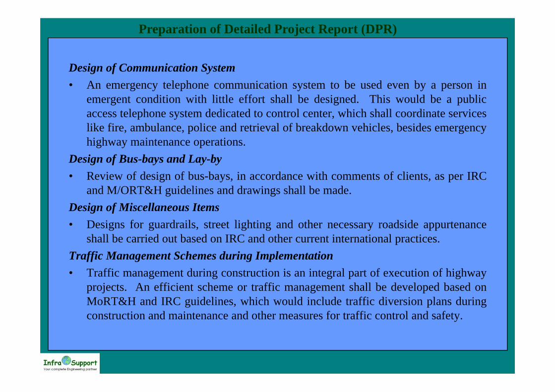
Design of Communication System• An emergency telephone communication system to be used even by a person in
emergent condition with little effort shall be designed. This would be a publicaccess telephone system dedicated to control center, which shall coordinate serviceslike fire, ambulance, police and retrieval of breakdown vehicles, besides emergencyhighway maintenance operations.
Design of Bus-bays and Lay-by• Review of design of bus-bays, in accordance with comments of clients, as per IRC
and M/ORT&H guidelines and drawings shall be made.Design of Miscellaneous Items• Designs for guardrails, street lighting and other necessary roadside appurtenance
shall be carried out based on IRC and other current international practices.Traffic Management Schemes during Implementation• Traffic management during construction is an integral part of execution of highway
projects. An efficient scheme or traffic management shall be developed based onMoRT&H and IRC guidelines, which would include traffic diversion plans duringconstruction and maintenance and other measures for traffic control and safety.
Preparation of Detailed Project Report (DPR)
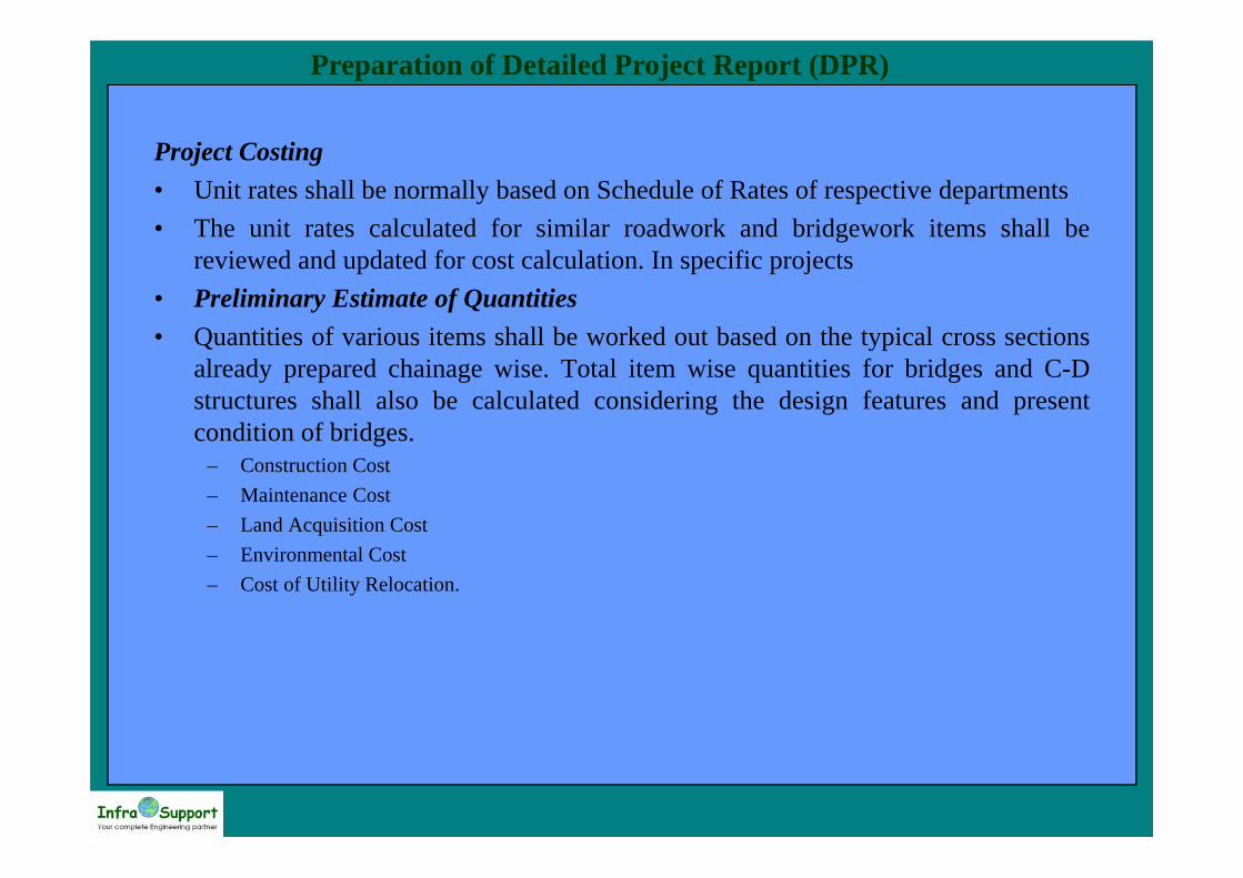
Project Costing• Unit rates shall be normally based on Schedule of Rates of respective departments• The unit rates calculated for similar roadwork and bridgework items shall be
reviewed and updated for cost calculation. In specific projects• Preliminary Estimate of Quantities• Quantities of various items shall be worked out based on the typical cross sections
already prepared chainage wise. Total item wise quantities for bridges and C-Dstructures shall also be calculated considering the design features and presentcondition of bridges.
– Construction Cost– Maintenance Cost– Land Acquisition Cost– Environmental Cost– Cost of Utility Relocation.

Preparation of Detailed Project Report (DPR)
Economic Analysis• In order to carry out the economic analysis, all economic costs shall be estimated by
each homogenous section. These costs comprise of the following:– Cost of construction/improvement– Vehicle operating costs and time costs– Accident costs– Social and environmental costs
Estimation of Project Benefits• The benefits from each improvement option shall be derived by using the approach
of "with" and "without" project scenario, for each homogeneous section. Thebenefits would comprise the following:
– VOC savings– Travel time savings– Savings in Accident costs– Socio-Environmental benefits
Preparation of Detailed Project Report (DPR)
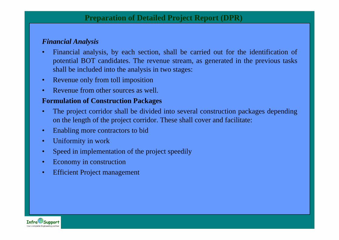
Financial Analysis• Financial analysis, by each section, shall be carried out for the identification of
potential BOT candidates. The revenue stream, as generated in the previous tasksshall be included into the analysis in two stages:
• Revenue only from toll imposition• Revenue from other sources as well.Formulation of Construction Packages• The project corridor shall be divided into several construction packages depending
on the length of the project corridor. These shall cover and facilitate:• Enabling more contractors to bid• Uniformity in work• Speed in implementation of the project speedily• Economy in construction• Efficient Project management