Embed Size (px)
Citation preview

PREMIUM SAND SCREEN TESTING MECHANICAL STRENGTH TESTS
MARCH 2004
Prepared for:
TUBULAR PERFORATING MANUFACTURING LTD.
Prepared by:
APA (U.S.A.) INC.
APRIL 30, 2004

1009 Long Prairie Rd. Suite 303.Flower Mound, TX 75022
Tel.: 972-724-9920♦ Fax: 972-355-9902
May 10, 2004
Job No. 50185
Tubular Perforating Manufacturing, Ltd. P.O. Box 2039 Conroe, Texas 77305 Attn: Ed Blackburne, Jr. Re: PREMIUM SAND SCREEN TESTING REPORT Dear Ed: Please find the attached final report documenting the mechanical testing of Tubular Perforating Manufacturing Ltd.’s new premium screen. The testing is preliminary to commercial sales of the screen. While professing an interest in cheaper premium screens, some of those operating companies, surveyed earlier for the marketing analysis, asked about the mechanical properties of the screen. Tubular Perforating Manufacturing Ltd. authorized the mechanical testing of the screen in Mohr Engineering, a division of Stress Engineering Services, Inc. The screen performed extremely well in all mechanical tests. The results of the tests are documented in this report along with the methodology of testing. From these results, APA believes the screen can hold up to the mechanical stresses and strains that are often incurred when installing the screens in the hole while maintaining its screening integrity. The screen is robust and can withstand a large delta pressure across it to the perforations in the base pipe in the event that the screen should be plugged and require an acid or jetting clean up treatment. Many of the tests were continued until destruction, which will be an advantage to those utilizing the screen in knowing the physical limitations of the screen. Even though the failures were recognized in the shrouds, there was not an indication of a wire mesh integrity problem. This artefact of the test would seem to indicate the robustness of the outer portion of the screen is carried into the inner mesh that is most important in retaining sand. APA, as a third party witness to these tests, is happy to supply this report as support to the mechanical superiority of Tubular Perforating Manufacturing Ltd.’s premium sand screen.
Yours sincerely, APA (USA) Inc.
John A. Johnson, P.E. Production Specialist
Encl.
TABLE OF CONTENTS
Page
LETTER OF TRANSMITTAL
CONCLUSIONS i
RECOMMENDATIONS ii
1.0 BACKGROUND 1
2.0 TEST METHODOLOGY 2
3.0 TESTING 4
3.1 Axial Tension Tests 4 3.1.1 Test Procedure 5 3.1.2 Test Results 6
3.2 Axial Compression Tests 7 3.2.1 Test Procedure 8 3.2.2 Test Results 9
3.3 Torsion Tests 10 3.3.1 Test Procedure 11 3.3.2 Test Results 12
3.4 Collapse Tests with Simulated Perforated Base Pipe 13 3.4.1 Test Procedure 13 3.4.2 Test Results 14
4.0 WIRE MESH INFORMATION 16
Premium Sand Screen Testing
i
CONCLUSIONS
1. TPM’s proprietary premium screen is robust and can stand up to the rigors of installation
in the well.
2. The mechanical test properties were taken on the screen itself where most of the
competitors test the screens on base pipe. (When the screens are tested on base pipe,
base pipe dominates. A manufacturer’s selection of base pipe will directly influence the
results of mechanical testing.) This fact should encourage operators to use TPM’s
premium screen as it has shown to be particularly tough on its own construction in both
tensile and compression.
3. Collapse and torque, however, will both be improved with the screen being on base pipe.
Collapse is the indicator as it went from 300 psi+ to over 7,500 psi when placed on base
pipe. Torque in most cases will be transferred to the base pipe.
4. Operators should feel confident to run TPM’s premium screens on to the target zone
even if there is significant pull or set down on the production assembly should the screen
get stuck on the way in the hole.
5. The collapse test on base pipe with the ports is considered an extreme test because:
a. The plugging agent was not sufficient for high differential pressure use.
b. It is expected that 7500 psi differential pressure is much higher than will be
actually seen across the screen.
c. The ports were not arrayed as in normal base pipe, only in 90° phases in one
plane and they were not the same size (3/4”, 5/8”, 1/2”, and 3/8”).
d. The blank surface areas of the test base pipe was not representative of the area
over which the pressure acting to deform the screen actually will have in
application.
Premium Sand Screen Testing

ii
RECOMMENDATIONS
1. Tensile and compression tests should be heralded as significant tests to operators so
that they will not be worried about the robustness of the screen.
2. Torque tests reflected no leak when torqued well past the elastic failure of the shrouds.
However, APA recommends that base pipe torque limits be used when running screen
assemblies in the well.
3. The collapse test on base pipe with the ports should be looked at again for the reasons
mentioned in the conclusions. APA feels that 7500 psi is a conservative collapse limit
for the screen on base pipe.
Premium Sand Screen Testing
1
1.0 BACKGROUND Tubular Perforating Manufacturing Ltd. (TPM) requested APA (U.S.A.) Inc. to
conduct a market analysis for their new proprietary designed premium sand
screen. An initial sand screen market survey of operating oil companies was
completed and given to TPM.
From that analysis, APA recommended that TPM do some initial testing to verify
the durability and strength of the TPM screen. Additionally, TPM was advised
that some sand retention and plugging information would be of interest to the
various operating companies surveyed.
TPM and APA agreed that tension; compression; compaction; torque; and leak
integrity tests should be performed at an independent lab. TPM would procure
wire mesh through Dorstener Wire Technology and would get information on
sand retention and plugging of the mesh. This report documents the results and
methodology in acquiring the mechanical test information.
Stress Engineering Services, Houston, Texas; Southwest Research Institute
(SwRI), San Antonio, Texas; and Centre for Frontier Engineering Research (C-
FER), Alberta, Canada were all contacted with regard to the testing of the
screens. Stress Engineering Services were chosen as they had the most
complete package of test equipment ready for testing. Stress was also the most
convenient test lab to TPM for shipping test samples and witnessing tests.
Premium Sand Screen Testing
2
2.0 TEST METHODOLOGY TPM and APA discussed the purpose of testing the screen. The major reason
for testing the screen was to have data to prove to prospective clients that the
screen was robust enough for them to utilize in their wells. Most mechanical
testing is conducted with the base pipe in place and generally reflects the
characteristics of the base pipe when testing. That is, the tensile strength
measurement is dominated by the base pipe and is routinely found at 95% of the
tensile of the base pipe. Likewise the compression and torque measurements
are reflective of the base pipe.
TPM and APA determined that testing utilizing base pipe would basically be a
comparison of the different base pipes being utilized. The base pipe chosen can
reasonably skew the tests. TPM proposes to let clients choose their own base
pipe as opposed to TPM affixing the screens to a particular base pipe. In light of
this decision, the methodology of the screen tests changed to checking the
robustness of the screen itself.
The data we feel is quite usable in the event that the screen is stuck during
installation and the screen is the point where the sticking occurs. The question is
how much weight can you pull or set down on the screen without creating some
damage to the screen. If the operator can pull or set down a certain amount that
is less than the elastic limit of the screen and does not create a leak path, it is
safe to assume the screen will be able to carry out its responsibility with out
pulling out of the hole to check the integrity. This information will allow the
operator to run on in the hole and save rig time and expense. Likewise, the
maximum torque on the screen was also tested.
Each of these mechanical strength tests was completed with a pump-in test
occurring simultaneous to the forces being applied to the screen. We reasoned
that if the test did not create a leak path, then the screen was robust enough to
handle the abuse applied to it without losing integrity until the point that the force
Premium Sand Screen Testing
3
surpassed the elastic limits of the screen. The one test conducted on base pipe
was a leak test created by ∆p across the screen. This must be done on base
pipe so the flow can be directed through the holes drilled in the base pipe.
Premium Sand Screen Testing

4
3.0 TESTING The procedure, test fixture, and results for each of the tests; collapse, tension,
compression, torsion, and leak integrity, are documented in the following sections
of the report.
Each screen sample was placed inside a pressure chamber constructed by Mohr
to maintain an external pressure on the sample while measuring the distortion
and external pressure through each of the mechanical tests. A diagram of the
pressure chamber and one screen sample is shown below:
The chamber is sealed around the sample and a pump is connected to the
chamber through a ½” port. A pressure transducer is attached in the other port in
the pressure sleeve.
3.1 Axial Tension Tests The screen sample had 2-4” OD pipe pieces welded on to either end. The end
pieces then had holes drilled through them to pin them into Mohr’s 1-million
Premium Sand Screen Testing

5
pound load frame. The 4” pipe did not run through the screen sample but was
used merely for attachment to the 2” pins on the load frame. Load was then
applied to the ends and the load and axial deflection were recorded. Initial tests
were conducted while holding pressure of 200-220 psi through the pressure
chamber on the outside of the screen to determine if a leak path were to occur
prior to tensile failure.
3.1.1 Test Procedure The following is the test procedure followed for the Axial Tension Tests:
• Equip screen sample with pipe ends drilled with 2” diameter holes to pin to load frame.
• Place pressure sleeve around screen sample with plugging agent pump and pressure monitor connected.
• Secure sample cell in load frame using 2” diameter pins.
• Pressure sleeve to 200-220 psi around screen sample.
• Slowly increase axial tension and monitor load until sample fails.
Failure is designated as the point at which the sample no longer holds 200-220
psi external pressure or surpasses the elastic limit of the screen sample in
tension.
Premium Sand Screen Testing

6
A picture of the test set-up is shown below:
3.1.2 Test Results The load was continually increased on the screen until there was a tear in the
outer shroud between the drilled holes in the shroud. The maximum tension
measured prior to the failure in the sample was 58,647 lb-f. The sample
stretched approximately 0.95 inches (4.75% of the length of the screen sample).
This elongation in the screen sample is greater than the base pipe would stand.
It was also noted that the sample did not leak even when the outer shroud
actually gave away. This should offer encouragement to those companies
running the TPM screens that the base pipe would actually fail in tension prior to
the screen stretching to failure. Theoretically, this test would indicate that any
pulling that was done during the installation would not interfere with the screen’s
ability to perform up to the actual failure of the base pipe itself.
Premium Sand Screen Testing

7
A picture of the failed sample is shown in the following:
NOTE: The failure is not a tear along the seam but in the drilled holes.
3.2 Axial Compression Tests The screen sample was again placed inside of the pressure sleeve with 200-220
psi external pressure added through the plugging agent pump. The sample
length was a bit longer to provide a shoulder to press on axially with the
calibrated Baldwin frame. The sample was placed between the faces of parallel
platens to add compression load while maintaining external pump pressure.
External pressure, load and axial deflection were measured while adding load to
the sample until compression failure.
Premium Sand Screen Testing

8
3.2.1 Test Procedure The following is the procedure for the Axial Compression Test:
• Weld short pipe end sections into the screen sample to prevent the ends from buckling when the load was added.
• Insert sample section in pressure sleeve and connect plugging agent pump and pressure monitor.
• Place platens on each end of the sample to insure equal compression load on bottom and top of screen sample.
• Pressurize sleeve to 200-220 psi using plugging agent pump.
• Slowly apply load using Baldwin load frame until a leak path occurs or the screen sample reaches elastic limit in compression.
A picture of the test set-up follows:
Premium Sand Screen Testing

9
3.2.2 Test Results Compression load was added until the screen sample failed at the very end of
the sample at 45, 469 lb-f where it came in contact with the top platen. The total
compression was 0.272” or 1.13% of the sample length. The sample never
developed a leak path during the test. When we determined the failure was on
the outer shroud on the end of the sample (see picture), the recommendation
was made to collapse the sample by pumping on the plugging agent pump. We
continued to pressure up on the sample until there was no further deflection on
the screen.
Top end failure in compression
The collapse phenomenon was quite interesting as the internal shroud collapsed
in three places around the circumference in the screen but all at the same
distance from the end of the screen. It appears that the first collapse as noted on
Premium Sand Screen Testing
10
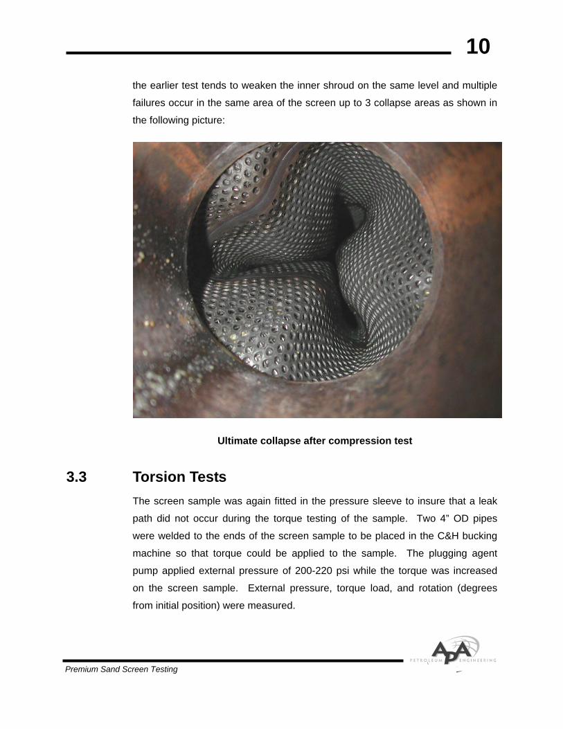
the earlier test tends to weaken the inner shroud on the same level and multiple
failures occur in the same area of the screen up to 3 collapse areas as shown in
the following picture:
Ultimate collapse after compression test
3.3 Torsion Tests The screen sample was again fitted in the pressure sleeve to insure that a leak
path did not occur during the torque testing of the sample. Two 4” OD pipes
were welded to the ends of the screen sample to be placed in the C&H bucking
machine so that torque could be applied to the sample. The plugging agent
pump applied external pressure of 200-220 psi while the torque was increased
on the screen sample. External pressure, torque load, and rotation (degrees
from initial position) were measured.
Premium Sand Screen Testing

11
3.3.1 Test Procedure The following procedure was followed in the Torsion Tests:
• Weld 4” OD end subs on screen sample for gripping in C&H’s bucking machine.
• Fit pressure sleeve over screen sample and connect plugging agent pump and external pressure monitor to the fixture.
• Insert test fixture into the bucking machine.
• Hook up Mohr’s 20,000 lb load cell on C&H’s four-foot moment arm to calculate torque.
• Install extensometer to outside of sample to calculate rotation on the sample.
• Pressure up the sleeve to 200-220 psi external pressure.
• Slowly add rotation through the bucking machine until a leak path develops in the sample or the torque elastic limit is reached. Two samples to be turned clockwise (expanding wrap on outer shroud) and two to be turned counter-clockwise (contracting the wrap on the outer shroud).
A picture of the test set-up is shown in the following:
Premium Sand Screen Testing
12
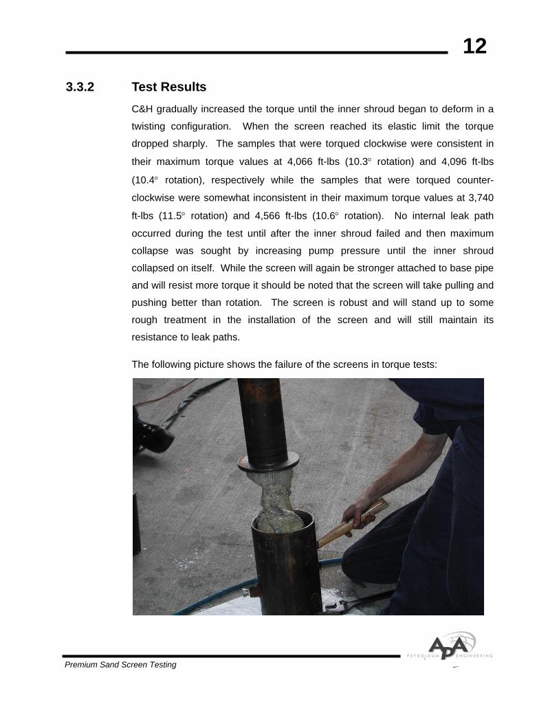
3.3.2 Test Results C&H gradually increased the torque until the inner shroud began to deform in a
twisting configuration. When the screen reached its elastic limit the torque
dropped sharply. The samples that were torqued clockwise were consistent in
their maximum torque values at 4,066 ft-lbs (10.3° rotation) and 4,096 ft-lbs
(10.4° rotation), respectively while the samples that were torqued counter-
clockwise were somewhat inconsistent in their maximum torque values at 3,740
ft-lbs (11.5° rotation) and 4,566 ft-lbs (10.6° rotation). No internal leak path
occurred during the test until after the inner shroud failed and then maximum
collapse was sought by increasing pump pressure until the inner shroud
collapsed on itself. While the screen will again be stronger attached to base pipe
and will resist more torque it should be noted that the screen will take pulling and
pushing better than rotation. The screen is robust and will stand up to some
rough treatment in the installation of the screen and will still maintain its
resistance to leak paths.
The following picture shows the failure of the screens in torque tests:
Premium Sand Screen Testing

13
This sample was torqued to 227° or 3/4 of a turn to total destruction without
internal leak path developing.
3.4 Collapse Tests with Simulated Perforated Base Pipe TPM made a 12” long section of 4” OD base pipe with four ports in it. This was
to simulate a base pipe so that collapse could be measured in the screen on top
of the base pipe. The four ports were 3/4”, 5/8”, 1/2”, and 3/8” in diameter and
were vented out through one central end port. A 6” length of screen was welded
over the base pipe and then the sample was placed in a 20-ksi-pressure vessel.
The central vent port was connected to the vessel head so that external pressure
could be applied to the sample to create erosion through the base pipe holes. To
fail, the three layers of mesh and the inner shroud would have to fail under
external pressure.
3.4.1 Test Procedure The following procedure was used in the Collapse Tests Simulated with
Perforated Base Pipe:
• Make a 4” OD base pipe 12” in length and drill four ports in the pipe in the diameter of 3/4”, 5/8”, 1/2”, and 3/8”.
• Weld screen sample over top of base pipe with central end port in one of the end plates.
• Place sample in 20-ksi-pressure vessel.
• Install pressure monitor to measure pressure exerted externally on screen.
• Apply external pressure to screen to attempt to create collapse or erosion in screen.
Premium Sand Screen Testing

14
The following picture is the set-up for this test:
3.4.2 Test Results Mohr applied pressure with a large capacity pump until an internal leak path was
established. The test reached a maximum of 7,504 psi. It is suspected that at
this level of pressure and at this late stage of testing, the plugging agent had
broken down sufficiently that it would not stand the high differential pressure.
Inspection of the screen showed no enlarged holes in the fine mesh although it
had deflected 0.15” at the 3/4” port center. It is believed by all of the witnesses
that the screen was capable of holding more pressure as no real damage had
occurred to any of the components of the screen.
Premium Sand Screen Testing

15
The following picture reflects the good shape the screen was still in after testing.
Premium Sand Screen Testing
16
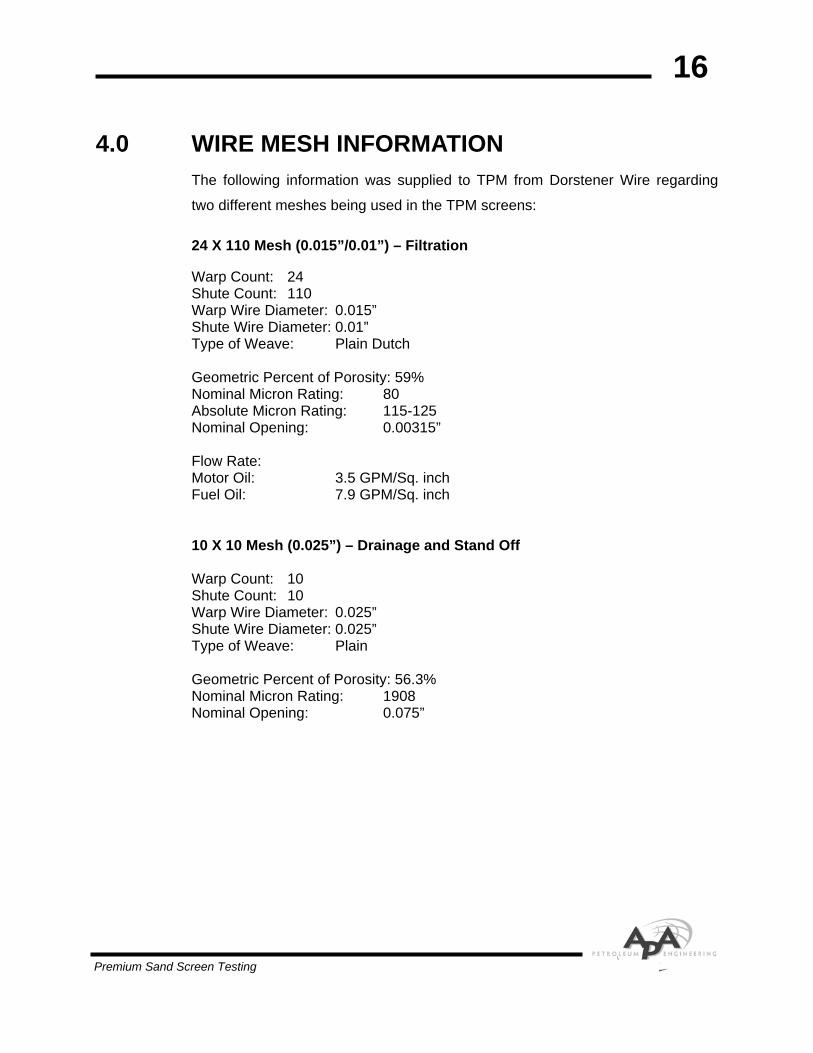
4.0 WIRE MESH INFORMATION The following information was supplied to TPM from Dorstener Wire regarding
two different meshes being used in the TPM screens:
24 X 110 Mesh (0.015”/0.01”) – Filtration
Warp Count: 24 Shute Count: 110 Warp Wire Diameter: 0.015” Shute Wire Diameter: 0.01” Type of Weave: Plain Dutch Geometric Percent of Porosity: 59% Nominal Micron Rating: 80 Absolute Micron Rating: 115-125 Nominal Opening: 0.00315” Flow Rate: Motor Oil: 3.5 GPM/Sq. inch Fuel Oil: 7.9 GPM/Sq. inch 10 X 10 Mesh (0.025”) – Drainage and Stand Off Warp Count: 10 Shute Count: 10 Warp Wire Diameter: 0.025” Shute Wire Diameter: 0.025” Type of Weave: Plain Geometric Percent of Porosity: 56.3% Nominal Micron Rating: 1908 Nominal Opening: 0.075”
Premium Sand Screen Testing


![The Study of Green Compression Strength of a Green Sand Mould … · 2014-10-21 · Jain [1] in his work said that the green compression strength of a green sand mould depends on](https://img.dokumen.tips/doc/110x75/5e983572fca485139d2679cb/the-study-of-green-compression-strength-of-a-green-sand-mould-2014-10-21-jain.jpg)