Embed Size (px)
Citation preview


PrefaceMaintenance ExperienceEditorial Committee
Maintenance ExperienceNewsroom
Address: ZTE Plaza, Keji Road South, Hi-Tech
Industrial Park, Nanshan District,
Shenzhen, P.R.China
Postal Code: 518057
Contact: Song Chunping
Tel: +86-755-26770600, 26771195
Fax: +86-755-26772236
Document Support Email: [email protected]
Technical Support Website: http://ensupport.
zte.com.cn
Director: Qiu Weizhao
Deputy Director: Chen Jianzhou
Editors:Jiang Guobing, Zhang Shoukui, Wu Feng,
Yuan Yufeng, Tang Hongxuan, Chen Huachun,
Li Gangyi, Gu Yu, Song Jianbo, Tian Jinhua,
Du Jianli, Qu Ruizheng, Liu Xianmin, Wang
Zhaozheng, L iu Wenjun, Lei Kun, Wang
Tiancheng, Cai Hongming, Wang Yapping
Technical Senior Editors:Hu Jia, Bai Jianwen
Executive Editor:Zhang Fan
Maintenance Experience Editor CommitteeZTE CorporationOctober, 2008
In this issue of ZTE's "Maintenance Experience", we continue to pass on various field reports and resolutions that are gathered by ZTE engineers and technicians around the world.
The content presented in this issue is as below: One Special Document Seven Maintenance Cases of ZTE's Data Products
Have you examined your service polices and procedures lately? Are you confident that your people are using all the tools at their disposal? Are they trained to analyze each issue in a logical manner that provides for less downtime and maximum customer service? A close look at the cases reveals how to isolate suspected faulty or mis-configured equipment, and how to solve a problem step by step, etc. As success in commissioning and service is usually a mix of both discovery and analysis, we consider using this type of approach as an example of successful troubleshooting investigations.
While corporate leaders maintain and grow plans for expansion, ZTE employees in all regions carry out with individual efforts towards internationalization of the company. Momentum continues to be built, in all levels, from office interns to veteran engineers, who work together to bring global focus into their daily work.
If you would like to subscribe to this magazine (electronic version) or review additional articles and relevant technical materials concerning ZTE products, please visit the technical support website of ZTE Corporation (http://ensupport.zte.com.cn).
If you have any ideas and suggestions or want to offer your contributions, you can contact us at any time via the following email: [email protected].
Thank you for making ZTE a part of your telecom experience!
Maintenance ExperienceBimonthly for Data Products
No.55 Issue 134, October 2008

Contents
ZESR Configuration 2
Master Node Remote Login on ZESR Ring Network 17
ZESR Millisecond Convergence 20
Double Independent Main Rings on ZESR 21
Address Superposition 22
Switch CPU Utilization Ratio Abnormity 24
Lighting Stroke Damage on Broadband Device 26
A Tip of Batch Pasting on Hyper Terminal and SecureCRT 27

October 2008 Issue 134
Maintenance Experience2
ZESR Configuration⊙ Zhu Changfei / ZTE Corporation
1 ZESR PrincipleZTE Ethernet Smart Ring (ZESR) is a
technique of Ethernet ring based on EAPS
protocol (RFC3619). ZESR allows network
administrators to create Ethernet rings.
It is like Fiber Distributed Data Interface
(FDDI) or SONET/SDH ring. When a link or a
node malfunction occurs, the switches which are
configured ZESR can recover within 50ms. The
exact time for recovering depends on the number
of nodes in the ring.
Ethernet Automatic Protection Switching
(EAPS) is a solution introduced by Extreme
Networks Corporation for Layer-2 loop problem.
Comparing with STP, the advantage of EAPS is
that EAPS takes less time than 50ms to hand
over the l ink and to resolve the problem of
communication when a link is down on the ring.
ZTE introduces ZESR, which is a technique
that has additional information based on EAPS
protocol. ZESR has the advantage of EAPS, that
is, the fast Layer-2 constringency capability. In
addition, ZESR has the networking capability in
complicated ring environments.
As shown in Figure 1, in the Ethernet ring, S1
is a master node, and other switches are transit
Key words:ZESR, Ethernet ring, EAPS
Figure 1. ZESR Principle

www.zte.com.cn
3Data Products
nodes. On the master node, one port is primary
and the other is secondary.
In the process of initialization, the secondary
port is blocked to prevent loop. When a transit
node finds that fault occurs in an adjacent link,
it will send a Link Down message to the master
node.
When the master node receives the Link
Down message, it clears FDB table and opens
secondary port to send RING-DOWN-FLUSH-FDB
messages to the transit nodes. The transit nodes
clear their FDB tables. After that, the switches learn
addresses again in a common way.
To prevent the master node from missing the
Link Down message, the master node sends
Health frames from primary port periodically. The
Health frame goes along the ring and it is received
by the master node on the secondary port.
If the secondary port does not receive the
frame within a designated time, the master
node considers that a link on the ring is broken.
Therefore, the master node takes action as if it
receives a Link Down message.
After that, master node still sends Health
frames periodically. If the Health frame is received
on the secondary port, the master node considers
that the link has recovered. Then the master node
clears the FDB table and sends RING-UP-FLUSH-
FDB messages to transit nodes again.
Before the master node f inds that l ink
recovers, the transit node adjacent to the link
finds that link recovers first. If the transit node
enables the corresponding port immediately, a
loop will generate. To avoid this situation, when
the transit node adjacent to the link finds that link
recovers, it does not enable the corresponding port
immediately. This state is called preforwarding.
This state is kept until the transit node receives the
RING-UP-FLUSH-FDB message from the master
node.
All Health frames, Link-Down messages, RING-
DOWN-FLUSH-FDB messages and RING-UP-
FLUSH-FDB messages are transmitted in
an independent control VLAN.
2 Basic Terms
2.1 ZESR Domain
A ZESR domain comprises a group of
switches with the same domain ID, control
VLAN and different protected VLANs. The
switches in the group connect to each
other, as shown in Figure 2. It is allowed to
be one or multiple ZESR domains on the
same physical ring. Each ZESR domain
can define the master node, transit nodes
and edge node of its own.
A ZESR domain may comprise one or
multiple rings connecting with each other.
A ring may include one or multiple ZESR
domains.
2.2 ZESR Ring
A physical ZESR ring is corresponding
to a ring Ethernet topology. When a ZESR
domain comprises multiple ZESR rings
that connect with each other, one of the
rings is the main ring of Level 0. Other
rings are segment links of different levels
on the main ring. When a ZESR domain
includes only one ring, the ring can be
configured as the main ring.
Figure 2. ZESR Domain
October 2008 Issue 134
Maintenance Experience4
2.3 Control VLAN
Protocol messages of ZESR are
transmitted in the control VLAN. Each
ZESR domain has a control VLAN.
2.4 Protected VLAN
Protected VLAN is also a service
VLAN. There are mult iple protected
VLANs in each ZESR domain. The
messages of user services are transmitted
in the protected VLANs. Layer-2 service
protection of service traffic is implemented
through pruning.
2.5 Master Node
Master node is the policy and control
node on a ZESR ring. There is a master
node on the main ring and each segment
link of different levels. These master nodes
control the main ring and segment links.
2.6 Transit Node
Except the master node on a ZESR
ring, other nodes are transit nodes. They
help the master node to detect the status
of ZESR ring and hand over the services under the
control of the master node.
2.7 Edge Node
On a ZESR ring, the node that connects with
more than two segment links is called edge node.
On the segment link with higher level, the edge
node is a master node or a transit node (including
two ports). On the segment link with lower level,
the edge node is an edge assistant node or an
edge control node (including only one port).
2.8 Edge Assistant Node
An edge assistant node is a transit node that
only has one port on the corresponding segment
link. It helps the master node or edge control node
on the segment link to detect the status of ZESR
ring and hand over the services. There mast be
one or two edge assistant nodes on different
segment links, but there may be no edge control
node. When there is only one edge assistant node,
the master node should be the edge control node.
2.9 Edge Control Node
An edge control node is the master node that
only has one port on the corresponding segment
link. It carries out policy and control on the
corresponding segment link together with the other
edge assistant node.
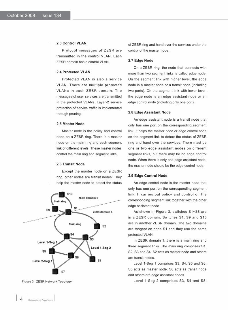
As shown in Figure 3, switches S1~S8 are
in a ZESR domain. Switches S1, S9 and S10
are in another ZESR domain. The two domains
are tangent on node S1 and they use the same
protected VLAN.
In ZESR domain 1, there is a main ring and
three segment links. The main ring comprises S1,
S2, S3 and S4. S2 acts as master node and others
are transit nodes.
Level 1-Seg 1 comprises S3, S4, S5 and S6.
S5 acts as master node. S6 acts as transit node
and others are edge assistant nodes.
Level 1-Seg 2 comprises S3, S4 and S8. Figure 3. ZESR Network Topology

www.zte.com.cn
5Data Products
S3 acts as edge control node. S4 acts as edge
assistant node and S8 acts as transit node.
Level 2-Seg 1 comprises S5, S6 and S7. S7
acts as master node and others are edge assistant
nodes.
2.10 Link Down Message
When a transit node finds that fault occurs on
an adjacent link, it will send a Link Down message
to the master node. After the master node receives
the Link Down message, it clears FDB table and
opens secondary port to send RING-DOWN-
FLUSH-FDB messages to the transit nodes. The
transit nodes clear their FDB tables. After that, the
switches learn addresses again in a common way.
2.11 Healthy Frame & Healthtime & Failtime
When the ring works normally, the master node
sends Health frames from primary port periodically.
The interval to send the frames is healthtime. When
the master node receives the Health frame on its
secondary port, it knows that the ring is working
normally, and then it refreshes its timer. The time
on the timer is failtime. Once the secondary port
does not receive the frame within failtime, the
master node considers that a link on the ring is
broken. Therefore, the master node takes action
as if it has received a Link Down message. The
failtime should be configured at least three times of
healthtime.
2.12 RING-DOWN-FLUSH-FDB
When the master node begins to hand over
the ring, it clears its FDB table and enables its
secondary port. Meanwhile, it sends RING-DOWN-
FLUSH-FDB messages to the transit nodes to
inform them to clear FDB tables and learn MAC
addresses again.
2.13 RING-UP-FLUSH-FDB
After the link fault occurs, if the master receives
Health frame on the secondary port again, the
master node considers that the link has
recovered. Then the master node clears
its FDB table and disables the secondary
port. It also sends RING-UP-FLUSH-FDB
messages to transit nodes to inform them
to clear their FDB tables.
2.14 Pre-Forwarding & preforwardtime
The transit node adjacent to the fault
link finds that link recovers earlier than
the master node. To avoid loop, the transit
node does not enable the corresponded
port immediately. Instead, it forwards
service data through its port until the
master node receives RING-UP-FLUSH-
FDB message.
However, if the transit node does not
receive the message indicating that master
node has received the RING-UP-FLUSH-
FDB message within a certain time period;
the transit node will enable its port. The
waiting time is called preforwardtime.
During the preforwardtime, the transit node
is in Pre-Forwarding state.
2.15 Pre-Up & preupdelaytime
To avoid loops caused by continual
link changes, master node does not block
its secondary port immediately when it
receives Health frame send by itself. It
waits for a duration time until it is certain
that the link is steady. The duration time
is called preupdelaytime. During the
preupdelaytime, the master node is in Pre-
Up state.
3 ZESR Detailed Introduction
3.1 Nonzero Level Segment Link
For complicated network, hierarchical
ZESR technique is introduced. When there
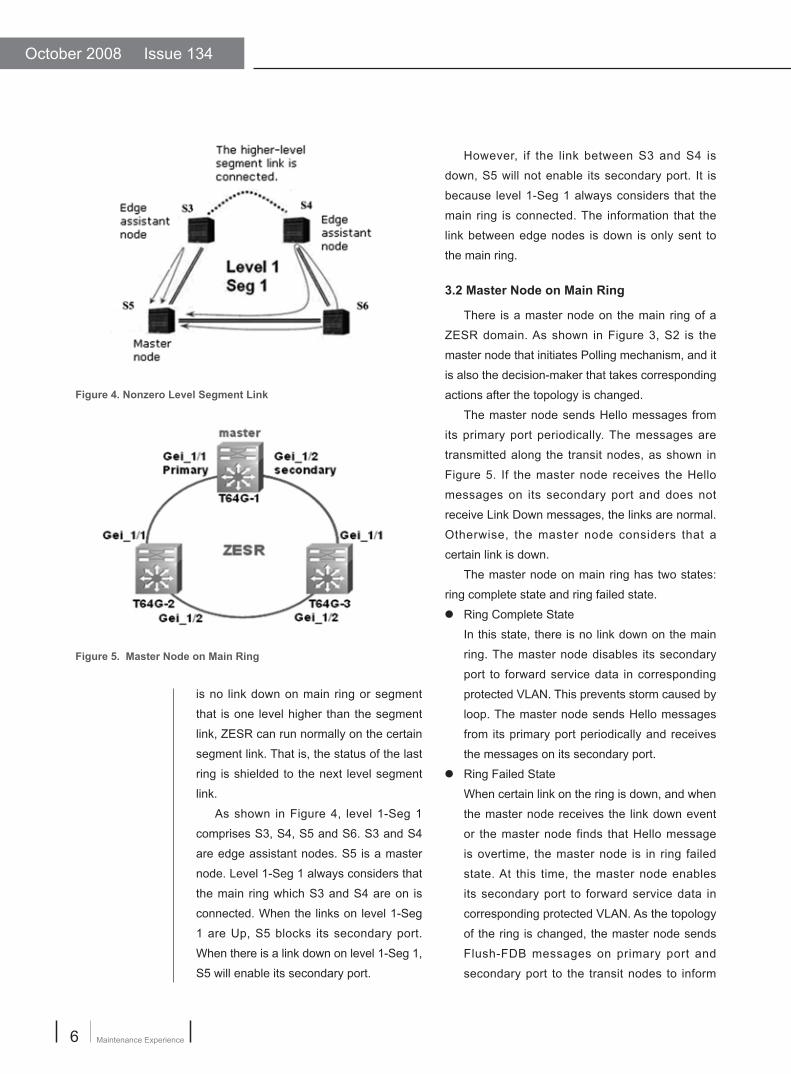
October 2008 Issue 134
Maintenance Experience6
is no link down on main ring or segment
that is one level higher than the segment
link, ZESR can run normally on the certain
segment link. That is, the status of the last
ring is shielded to the next level segment
link.
As shown in Figure 4, level 1-Seg 1
comprises S3, S4, S5 and S6. S3 and S4
are edge assistant nodes. S5 is a master
node. Level 1-Seg 1 always considers that
the main ring which S3 and S4 are on is
connected. When the links on level 1-Seg
1 are Up, S5 blocks its secondary port.
When there is a link down on level 1-Seg 1,
S5 will enable its secondary port.
However, if the link between S3 and S4 is
down, S5 will not enable its secondary port. It is
because level 1-Seg 1 always considers that the
main ring is connected. The information that the
link between edge nodes is down is only sent to
the main ring.
3.2 Master Node on Main Ring
There is a master node on the main ring of a
ZESR domain. As shown in Figure 3, S2 is the
master node that initiates Polling mechanism, and it
is also the decision-maker that takes corresponding
actions after the topology is changed.
The master node sends Hello messages from
its primary port periodically. The messages are
transmitted along the transit nodes, as shown in
Figure 5. If the master node receives the Hello
messages on its secondary port and does not
receive Link Down messages, the links are normal.
Otherwise, the master node considers that a
certain link is down.
The master node on main ring has two states:
ring complete state and ring failed state.● Ring Complete State
In this state, there is no link down on the main
ring. The master node disables its secondary
port to forward service data in corresponding
protected VLAN. This prevents storm caused by
loop. The master node sends Hello messages
from its primary port periodically and receives
the messages on its secondary port.● Ring Failed State
When certain link on the ring is down, and when
the master node receives the link down event
or the master node finds that Hello message
is overtime, the master node is in ring failed
state. At this time, the master node enables
its secondary port to forward service data in
corresponding protected VLAN. As the topology
of the ring is changed, the master node sends
Flush-FDB messages on primary port and
secondary port to the transit nodes to inform
Figure 4. Nonzero Level Segment Link
Figure 5. Master Node on Main Ring

www.zte.com.cn
7Data Products
them to clear their FDB tables that are related
to protected VLAN.
The states changes are shown in Figure 6.
3.3 Master Node on Segment Link
There is a master node (master node of the
segment link) on each segment link. As shown
in Figure 3, S8 is the master that initiates Polling
mechanism. It is also the decision-maker that
takes corresponding actions after the topology is
changed.
The master node sends Hello messages from
its primary port and secondary port periodically.
The messages are transmitted along the transit
nodes. At last, the Hello messages arrive at the
edge assistant node. The edge assistant node is
responsible for sending the Hello messages back
to the master node through its access ports, as
shown in Figure 7. If the master node receives the
Hello messages on its primary port and secondary
port, and it does not receive Link Down messages,
the links are normal. Otherwise, if the master does
not receive Hello messages on either of the two
ports, the master node considers that a certain link
is down.
The master node on segment link has two
states: Seg complete state and Seg failed state.● Seg Complete State
In this state, there is no link down on the
segment link. The master node disables its
secondary port to forward service data in
corresponding protected VLAN. This prevents
storm caused by loop. The master node sends
Hello messages from its primary port and
secondary port periodically. The messages are
transmitted along the transit nodes. At last, the
Hello messages arrive at the edge assistant
node. The edge assistant node sends the Hello
messages back to the master node through its
access ports. The Hello messages return to
master node on the primary port and secondary
port.
● Seg Failed State
When certain link on the segment link
is down, and when the master node
receives the link down event or the
master node finds that Hello message
is overtime, the master node is in Seg
Failed State. At this time, the master
node enables its secondary port to
forward service data in corresponding
protected VLAN. As the topology of the
Figure 6. State Changes
Figure 7. Hello Messages on Segment Link
October 2008 Issue 134
Maintenance Experience8
nodes on main ring or segment link for turning
to Complete state, the transit node transfers to
forwarding state automatically.
3.5 Edge Assistant Node
An edge assistant node is a transit node that
only has one port accessed to segment link. It
is responsible for monitoring the state of master
node on segment link. When the edge assistant
node finds it is out of touch with the master node, it
becomes the temporary master and sends RING-
DOWN-FLUSH-FDB messages, indicating that the
segment link is in Failed state.
Besides the three states of common transit
node, edge assistant node has another two states.● Master-Up state
Edge assistant node receives Hello messages
from master node and sends echo messages
on the access port periodically. If the timer is
not overtime, the edge assistant node is in
Master-Up state.● Master-Down state
When edge assistant node does not receive
Hello messages from master node on the
access port within designated time, or when
edge assistant node receives events about link
intermitting and port is in Links-Down state, the
edge assistant node is in Master-Down state.
Once it turns to Master-Down from Master-Up,
if the segment link is in Complete state, the
link will turn to Failed state. Meanwhile, edge
assistant node sends RING-DOWN-FLUSH-
FDB messages to the nodes on segment link
and upper level.
3.6 Primary Port and Secondary Port
On a master node or a transit node (except
edge assistant node), one of the two ports
accessing to ZESR ring is primary port, the other is
secondary port. The role of the ports is configured
by users. Primary port and secondary port have
different functions.
segment link is changed, the master
node sends Flush-FDB messages on
primary port and secondary port to the
transit nodes on the segment link and
corresponding nodes of upper level to
inform them to clear their FDB tables
that are related to protected VLAN.
For edge control node, it is similar with
the master node on segment link. The
difference is that the edge control sends
Hello messages only on its access ports
and it only monitors the link at its access
port side.
3.4 Transit Node
A transit node detects the state of
ZESR links connecting to itself directly. It
informs the master node and edge nodes
of the link changes.
Transit node has the following states.● Links-Up state
I n n o r m a l s i t u a t i o n , t h e p o r t s
connecting to the ZESR link are in
Links-Up state.● Links-Down state
When transit node is in Links-Down
state, the main ring (or segment link) is in
Failed state. At least one of the two ports
that connect to the ZESR link is DOWN. ● Pre-Forwarding state
This is an instantaneous state before
the l ink recovers. When a transit
node is in this state, the port that was
down becomes up and the service
forwarding function of protected VLAN
is disabled. When the main ring (or
segment link) is in Complete state, the
transit node can forward service data.
ZESR provides a backup mechanism
to recover the temporary-blocked port
and trigger state switch. If the transit
node does not receive messages from

www.zte.com.cn
9Data Products
Master node on main ring sends loop-state
detection message from its primary port. If master
node receives the message on its secondary port,
the ring is complete and the secondary port should
be blocked to prevent a loop. If master node does
not receive the loop-state detection message
within designated time, there is fault on the main
ring. At this time, the secondary port should be
enabled to ensure smooth communication. When
the secondary port is blocked, master node does
not forward flush messages that it receives from
segment links of different levels. Otherwise, it
forwards these flush messages.
Master node on segment link sends loop-
state detection message from its primary port
and secondary port. If it receives the message
on its primary port and secondary port, the ring
is complete and the secondary port should be
blocked to prevent a loop. If master node does not
receive the loop-state detection message within
designated time, there is fault on the main ring. At
this time, the secondary port should be enabled to
ensure smooth communication.
The primary port and secondary port on a
transit node have the same functions. The role of
the ports is also configured by users.
3.7 Access Port
Only one port on an edge assistant port (edge
control port) is on the segment link. This port is
called access port. The port is responsible for
receiving (sending) Hello messages from master
node on segment link, receiving intermitting
events and flush messages. Edge assistant
node judges the state of master node on the
segment link according to the Hello messages and
intermitting events that it receives. Besides, it also
helps to maintain flush messages. No matter the
flush messages are received on access port or
generated by the segment link the node locates,
the messages are sent to corresponding ports on
upper level segment link or the main ring to hand
over service.
3.8 ZESR Convergence Speed
The ZESR convergence speed is
related to the following factors.● Refreshing speed and capacity of MAC
address table● The number of ports that need to
refresh address table● STP handover speed on a port● The number of ports that participate in
STP handover● The number of ZESR domains when
there are multiple domains
4 Configuring ZESRTo conf igure ZESR, perform the
following steps.
1. To configure ZESR protect ion
instance binding, use the fol lowing
command.
ZXR10(config)#zesr ctrl-vlan <vlan-
id> protect-instance <0-16>
This binds the control VLAN to STP
instance that needs protection. The STP
instance is configured in STP module.
2. To configure the role of ZESR main
ring, use the following command.
ZXR10(config)#zesr ctrl-vlan <vlan-
id> major-level role < master | transit >
<port1> <port2>
This configures the role of ZESR
main ring. For the master node, the first-
configured port is the primary port, and the
second-configured port is the secondary
port. For transit node, the role of the two
ports is the same.
3. To configure the role of master node
on ZESR segment link, use the following
command.
ZXR10(config)#zesr ctrl-vlan <vlan-
id> level <1-2> role seg <1-4> master

October 2008 Issue 134
Maintenance Experience10
<port1> <port2>
This configures the role of master node
on ZESR segment link. Parameter level <1-2> identifies the level and parameter
seg <1-4> identifies the segmentp. For
the master node, the first-configured
port is the primary port, and the second-
configured port is the secondary port.
Master node sends Hello messages
and detects whether the link is complete
through the secondary port.
4. To configure the role of transit node
on ZESR segment link, use the following
command.
ZXR10(config)#zesr ctrl-vlan <vlan-
id> level <1-2> role seg <1-4> transit <port1> <port2>
This configures the role of transit node
on ZESR segment link. Parameter level <1-2> identifies the level and parameter
seg <1-4> identifies the segment. For
transit node, the two ports have the same
role and they forward Hello messages.
5. To conf igure the role of edge
assistant node on ZESR segment link, use
the following command.
ZXR10(config)#zesr ctrl-vlan <vlan-
id> level <1-2> seg <1-4> role edge-assistant <port1>
This configures the role of edge
assistant node on ZESR segment link.
Parameter level <1-2> identifies the level
and parameter seg <1-4> identifies the
segment. Edge assistant sends Hello
echos.
6. To configure the role of edge control
node on ZESR segment link, use the
following command.
ZXR10(config)#zesr ctrl-vlan <vlan-
id> level <1-2> seg <1-4> role edge-control <port1>
This configures the role of edge control
node on ZESR segment link. Parameter level <1-2> identifies the level and parameter seg <1-4>
identifies the segment. Edge control node sends
Hello messages and detects whether the link is
complete.
7. To configure preforward parameter and
preup parameter of transit node, use the following
command.
ZXR10(config)#zesr ctrl-vlan < vlan-id >
major-level | level <1-2> seg <1-4> preforward <1-600> preup <0-500>
This configures preforward parameter and
preup parameter of transit node. Parameter
preforward <1-600> is the duration of preforward
state, and preup <0-500> is the duration of preup
state. They are in unit of second. The duration of
preforward state should be the same in the whole
domain. The duration preup state is effective on
control node. The requirement is preforward –
preup >=1.
8. To configure hello parameter and fai l
parameter of transit node, use the following
command.
ZXR10(config)#zesr ctrl-vlan < vlan-id >
major-level | level <1-2> seg <1-4> hello <1-6>
fail <3-18>
This configures hello parameter and fail
parameter of transit node. Parameter hello <1-6> is
the interval for sending Hello messages. Parameter
fail <3-18> is the timeout of Hello messages. They
are in unit of second and are effective on control
node. The requirement is hello*3 <=fail.
9. To configure restart-time parameter of ZESR
node, use the following command.
ZXR10(config)#zesr restart-time <30-600>
This configures restart-time parameter of ZESR
node. When line interface card and the rack are
rebooted, ZESR port is blocked within the restart-
time. It is effective on transit node and edge
assistant node, in unit of second.
10. To view ZESR configuration information,
use the following command.
www.zte.com.cn
11Data Products
ZXR10(config)#show zesrThis displays ZESR conf igurat ion. This
command can be used in all modes.
ZXR10(config)#show zesr briefThis displays brief ZESR configuration. This
command can be used in all modes.
5 ZESR Configuration Examples
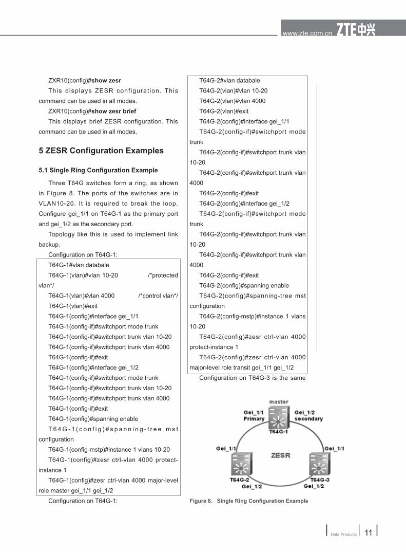
5.1 Single Ring Configuration Example
Three T64G switches form a ring, as shown
in Figure 8. The ports of the switches are in
VLAN10-20. It is required to break the loop.
Configure gei_1/1 on T64G-1 as the primary port
and gei_1/2 as the secondary port.
Topology like this is used to implement link
backup.
Configuration on T64G-1:
T64G-1#vlan databale
T64G-1(vlan)#vlan 10-20 /*protected
vlan*/
T64G-1(vlan)#vlan 4000 /*control vlan*/
T64G-1(vlan)#exit
T64G-1(config)#interface gei_1/1
T64G-1(config-if)#switchport mode trunk
T64G-1(config-if)#switchport trunk vlan 10-20
T64G-1(config-if)#switchport trunk vlan 4000
T64G-1(config-if)#exit
T64G-1(config)#interface gei_1/2
T64G-1(config-if)#switchport mode trunk
T64G-1(config-if)#switchport trunk vlan 10-20
T64G-1(config-if)#switchport trunk vlan 4000
T64G-1(config-if)#exit
T64G-1(config)#spanning enable
T 6 4 G - 1 ( c o n f i g ) # s p a n n i n g - t r e e m s t
configuration
T64G-1(config-mstp)#instance 1 vlans 10-20
T64G-1(config)#zesr ctrl-vlan 4000 protect-
instance 1
T64G-1(config)#zesr ctrl-vlan 4000 major-level
role master gei_1/1 gei_1/2
Configuration on T64G-1:
T64G-2#vlan databale
T64G-2(vlan)#vlan 10-20
T64G-2(vlan)#vlan 4000
T64G-2(vlan)#exit
T64G-2(config)#interface gei_1/1
T64G-2(config-if)#switchport mode
trunk
T64G-2(config-if)#switchport trunk vlan
10-20
T64G-2(config-if)#switchport trunk vlan
4000
T64G-2(config-if)#exit
T64G-2(config)#interface gei_1/2
T64G-2(config-if)#switchport mode
trunk
T64G-2(config-if)#switchport trunk vlan
10-20
T64G-2(config-if)#switchport trunk vlan
4000
T64G-2(config-if)#exit
T64G-2(config)#spanning enable
T64G-2(config)#spanning-tree mst
configuration
T64G-2(config-mstp)#instance 1 vlans
10-20
T64G-2(config)#zesr ctrl-vlan 4000
protect-instance 1
T64G-2(config)#zesr ctrl-vlan 4000
major-level role transit gei_1/1 gei_1/2
Configuration on T64G-3 is the same
Figure 8. Single Ring Configuration Example

October 2008 Issue 134
Maintenance Experience12
as that on T64G-2.
Configuration information on T64G-1 is
shown below.
T64G-1 (config)#show zesr
ZESR domain:
ctrl vlan 4000 /* control
VLAN*/
ports gei_1/1(Primary) gei_1/
2(Secondary) /*primary port and
secondary port on master node*/
node type MASTER /*node
type*/
mode standard /*MAC
address learn ing mode, i t i s here
standard*/
ring Up /*current working
state of ring. It can not be up under mis-
configuration*/
switch times 5 /*handover
times of the ring. Link fault occurred and
recovered twice.*/
healthtime: 1ms /*interval for
sending healthy frames*/
failtime: 3ms /*timeout of healthy
frames*/
Brief configuration information on
T64G-1 and T64G-2 is shown below.
T64G-1 (config)#show zesr brief
ctrl-vlan: 4000 protectinstance: 1
level seg role port port
level-state switch-times
major master gei_1/1(P) gei_1/2(S)
up 1
T64G-2 (config)#show zesr brief
ctrl-vlan: 4000 protectinstance: 1
level seg role port port level-state
switch-times
major transit gei_1/1(P) gei_1/2(S)
up 1
5 . 2 S i n g l e R i n g M u l t i p l e I n s t a n c e s Configuration Example
Four T64G switches form a ring, as shown
in Figure 9. The ports of the switches are in
VLAN10-20 and VLAN30-40. It is required to break
the loop and implement load balance. Service
traffic in VLAN 10-20 goes through T64G-1,
T64G-2 and T64G-4. Service traffic in VLAN 30-40
goes through T64G-1, T64G-3 and T64G-4.
To meet the requirements, configure two
MSTP instances, instance 1 and instance 2. Map
VLAN10-20 to instance 1 and map VLAN30-40
to instance 2. VLAN 4000 protects instance 1, in
which gei_1/1 on T64G-1 is configured as primary
port and gei_1/2 as secondary port. VLAN4001
protects instance 2, in which gei_1/2 on T64G-1
is configured as primary port and gei_1/1 as
secondary port.
Topology like this is used to implement load
balance and link backup.
Configuration on T64G-1:
T64G-1#vlan databale
T64G-1(vlan)#vlan 10-20 /*protected
vlan*/
T64G-1(vlan)#vlan 30-40 /*protected
vlan*/
T64G-1(vlan)#vlan 4000-4001 /*control
vlan*/
T64G-1(vlan)#exit
T64G-1(config)#interface gei_1/1
T64G-1(config-if)#switchport mode trunk
T64G-1(config-if)#switchport trunk vlan 10-20Figure 9. Single Ring Multiple Instances Configuration Example

www.zte.com.cn
13Data Products
Maintenance Materials
4000-4001
T64G-1(config-if)#exit
T64G-2(config)#spanning enable
T64G-2(config)#spanning-tree mst
configuration
T64G-2(config-mstp)#instance 1 vlans
10-20
T64G-1(config-mstp)#instance 2 vlans
30-40
T64G-2(config)#zesr ctrl-vlan 4000
protect-instance 1
T64G-2(config)#zesr ctrl-vlan 4001
protect-instance 2
T64G-2(config)#zesr ctrl-vlan 4000
major-level role transit gei_1/1 gei_1/2
T64G-2(config)#zesr ctrl-vlan 4001
major-level role transit gei_1/1 gei_1/2
Configuration on T64G-3 and T64G-4
are the same as on T64G-2.
Brief configuration information on
T64G-1 is shown below.
T64G-1 (config)#show zesr b
ctrl-vlan: 4000 protectinstance: 1
level seg role port port
level-state switch-times
major master gei_1/1(P) gei_1/
2(S) up 1
ctrl-vlan: 4001 protectinstance: 1
level seg role port port
level-state switch-times
major master gei_1/2(P) gei_1/
1(S) up 1
Brief configuration information on
T64G-2 is shown below.
T64G-2 (config)#show zesr b
ctrl-vlan: 4000 protectinstance: 1
level seg role port port
level-state switch-times
major transit gei_1/1(P) gei_1/
2(S) up 1
ctrl-vlan: 4001 protectinstance: 1
T64G-1(config-if)#switchport trunk vlan 30-40
T64G-1(conf ig- i f )#switchport t runk vlan
4000-4001
T64G-1(config-if)#exit
T64G-1(config)#interface gei_1/2
T64G-1(config-if)#switchport mode trunk
T64G-1(config-if)#switchport trunk vlan 10-20
T64G-1(config-if)#switchport trunk vlan 30-40
T64G-1(conf ig- i f )#switchport t runk vlan
4000-4001
T64G-1(config-if)#exit
T64G-1(config)#spanning enable
T 6 4 G - 1 ( c o n f i g ) # s p a n n i n g - t r e e m s t
configuration
T64G-1(config-mstp)#instance 1 vlans 10-20
T64G-1(config-mstp)#instance 2 vlans 30-40
T64G-1(config)#zesr ctrl-vlan 4000 protect-
instance 1
T64G-1(config)#zesr ctrl-vlan 4001 protect-
instance 2
T64G-1(config)#zesr ctrl-vlan 4000 major-level
role master gei_1/1 gei_1/2
T64G-1(config)#zesr ctrl-vlan 4001 major-level
role master gei_1/2 gei_1/1
Configuration on T64G-2:
T64G-2#vlan databale
T64G-2(vlan)#vlan 10-20
T64G-1(vlan)#vlan 30-40
T64G-2(vlan)#vlan 4000-4001
T64G-2(vlan)#exit
T64G-2(config)#interface gei_1/1
T64G-1(config-if)#switchport mode trunk
T64G-1(config-if)#switchport trunk vlan 10-20
T64G-1(config-if)#switchport trunk vlan 30-40
T64G-1(conf ig- i f )#switchport t runk vlan
4000-4001
T64G-1(config-if)#exit
T64G-2(config)#interface gei_1/2
T64G-1(config-if)#switchport mode trunk
T64G-1(config-if)#switchport trunk vlan 10-20
T64G-1(config-if)#switchport trunk vlan 30-40
T64G-1(conf ig- i f )#switchport t runk vlan

October 2008 Issue 134
Maintenance Experience14
level seg role port port
level-state switch-times
major transit gei_1/1(P) gei_1/
2(S) up 1
5.3 Multi-Level-Ring Configuration Example
Four T64G switches form a ring, as
shown in Figure 10. The ports of the
four switches are in VLAN10-20, ports
of T64G-1, T64G-2 and T64G-4 are also
in VLAN30-40. It is required that there
is no loop in the network and any link
fault should not affect the services in the
network.
To meet the requirements, use VLAN
4000 as the control VLAN of protected
VLAN10-20 and use VLAN 4001 as the
control VLAN of VLAN30-40. Devide the
network into two levels:● T64G-1, T64G-2 and T64G-4 are in
major-level (level 0), and T64G-1 is the
master node.● T64G-2, T64G-3 and T64G-4 are in
level-1 seg-1, and T64G-2 is the edge
control node.
Configure instance 1 on the four
swi tches, and map VLAN 10-20 to
instance 1. Configure instance 2 on
T64G-1, T64G-2 and T64G-4, and map
VLAN30-40 to instance 2. Configure VLAN 4000
to protect instance 1 and VLAN 4001 to protect
instance 2.
Configuration on T64G-1:
T64G-1#vlan databale
T64G-1(vlan)#vlan 10-20
T64G-1(vlan)#vlan 30-40
T64G-1(vlan)#vlan 4000-4001 /*control
VLAN*/
T64G-1(vlan)#exit
T64G-1(config)#interface gei_1/1
T64G-1(config-if)#switchport mode trunk
T64G-1(config-if)#switchport trunk vlan 10-20
T64G-1(config-if)#switchport trunk vlan 30-40
T64G-1(conf ig- i f )#switchport t runk vlan
4000-4001
T64G-1(config-if)#exit
T64G-1(config)#interface gei_1/2
T64G-1(config-if)#switchport mode trunk
T64G-1(config-if)#switchport trunk vlan 10-20
T64G-1(config-if)#switchport trunk vlan 30-40
T64G-1(conf ig- i f )#switchport t runk vlan
4000-4001
T64G-1(config-if)#exit
T64G-1(config)#spanning enable
T 6 4 G - 1 ( c o n f i g ) # s p a n n i n g - t r e e m s t
configuration
T64G-1(config-mstp)#instance 1 vlans 10-20
T64G-1(config-mstp)#instance 2 vlans 30-40
T64G-1(config)#zesr ctrl-vlan 4000 protect-
instance 1
T64G-1(config)#zesr ctrl-vlan 4001 protect-
instance 2
T64G-1(config)#zesr ctrl-vlan 4000 major-level
role master gei_1/1 gei_1/2
T64G-1(config)#zesr ctrl-vlan 4001 major-level
role master gei_1/2 gei_1/1
Configuration on T64G-2:
T64G-2#vlan databale
T64G-2(vlan)#vlan 10-20
T64G-2(vlan)#vlan 30-40
T64G-2(vlan)#vlan 4000-4001Figure 9. Single Ring Multiple Instances Configuration Example

www.zte.com.cn
15Data Products
T64G-2(vlan)#exit
T64G-2(config)#interface gei_1/1
T64G-2(config-if)#switchport mode trunk
T64G-2(config-if)#switchport trunk vlan 10-20
T64G-2(config-if)#switchport trunk vlan 30-40
T64G-2(conf ig- i f )#switchport t runk vlan
4000-4001
T64G-2(config-if)#exit
T64G-2(config)#interface gei_1/2
T64G-2(config-if)#switchport mode trunk
T64G-2(config-if)#switchport trunk vlan 10-20
T64G-2(config-if)#switchport trunk vlan 4000
T64G-2(config-if)#exit
T64G-2(config)#interface gei_1/3
T64G-2(config-if)#switchport mode trunk
T64G-2(config-if)#switchport trunk vlan 10-20
T64G-2(config-if)#switchport trunk vlan 30-40
T64G-2(conf ig- i f )#switchport t runk vlan
4000-4001
T64G-2(config-if)#exit
T64G-2(config)#spanning enable
T 6 4 G - 2 ( c o n f i g ) # s p a n n i n g - t r e e m s t
configuration
T64G-2(config-mstp)#instance 1 vlans 10-20
T64G-2(config-mstp)#instance 2 vlans 30-40
T64G-2(config)#zesr ctrl-vlan 4000 protect-
instance 1
T64G-2(config)#zesr ctrl-vlan 4001 protect-
instance 2
T64G-2(config)#zesr ctrl-vlan 4000 major-level
role transit gei_1/1 gei_1/3
T64G-2(config)#zesr ctrl-vlan 4000 level 1 seg
1 role edge-control gei_1/2
T64G-2(config)#zesr ctrl-vlan 4001 major-level
role transit gei_1/1 gei_1/3
Configuration on T64G-3
T64G-3#vlan databale
T64G-3(vlan)#vlan 10-20
T64G-3(vlan)#vlan 4000
T64G-3(vlan)#exit
T64G-3(config)#interface gei_1/1
T64G-3(config-if)#switchport mode trunk
T64G-3(config-if)#switchport trunk vlan
10-20
T64G-3(config-if)#switchport trunk vlan
4000
T64G-3(config-if)#exit
T64G-3(config)#interface gei_1/2
T64G-3(config-if)#switchport mode
trunk
T64G-3(config-if)#switchport trunk vlan
10-20
T64G-3(config-if)#switchport trunk vlan
50-60
T64G-3(config-if)#switchport trunk vlan
4000
T64G-3(config-if)#exit
T64G-3(config)#spanning enable
T64G-3(config)#spanning-tree mst
configuration
T64G-3(config-mstp)#instance 1 vlans
10-20
T64G-3(config)#zesr ctrl-vlan 4000
protect-instance 1
T64G-3(config)#zesr ctrl-vlan 4000
level 1 seg 1 role transit gei_1/1 gei_1/2
Configuration on T64G-4 is similar
with that of T64G-2. The difference is
that T64G-4 is an edge assistant node
instead of an edge control node. The
corresponding command is changed, as
shown below.
T64G-4(config)#zesr ctrl-vlan 4000
level 1 seg 1 role edge-a gei_1/2
Brief configuration information of the
four switches is shown below.
T64G-1 (config)#show zesr brief
ctrl-vlan: 4000 protectinstance: 1
level seg role port port
level-state switch-times
major master gei_1/1(P) gei_1/
2(S) up 1
ctrl-vlan: 4001 protectinstance: 1
level seg role port port
October 2008 Issue 134
Maintenance Experience16
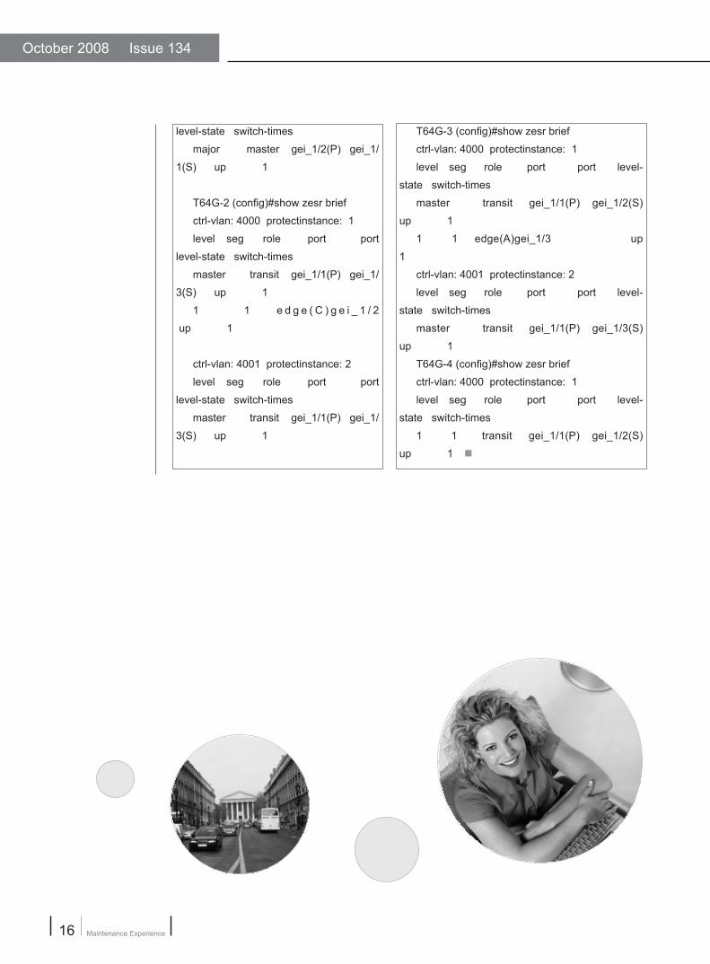
T64G-3 (config)#show zesr brief
ctrl-vlan: 4000 protectinstance: 1
level seg role port port level-
state switch-times
master transit gei_1/1(P) gei_1/2(S)
up 1
1 1 edge(A)gei_1/3 up
1
ctrl-vlan: 4001 protectinstance: 2
level seg role port port level-
state switch-times
master transit gei_1/1(P) gei_1/3(S)
up 1
T64G-4 (config)#show zesr brief
ctrl-vlan: 4000 protectinstance: 1
level seg role port port level-
state switch-times
1 1 transit gei_1/1(P) gei_1/2(S)
up 1 ■
level-state switch-times
major master gei_1/2(P) gei_1/
1(S) up 1
T64G-2 (config)#show zesr brief
ctrl-vlan: 4000 protectinstance: 1
level seg role port port
level-state switch-times
master transit gei_1/1(P) gei_1/
3(S) up 1
1 1 e d g e ( C ) g e i _ 1 / 2
up 1
ctrl-vlan: 4001 protectinstance: 2
level seg role port port
level-state switch-times
master transit gei_1/1(P) gei_1/
3(S) up 1

www.zte.com.cn
17Data Products
Master Node Remote Login on ZESR Ring Network⊙Yang Fei / ZTE Corporation
Key words:ZESR, Primary, management VLAN, Telnet
Network TopologyAs shown in Figure 1, three T160G devices
construct ZESR ring network, and they act as HL,
XDJ and NFHY node respectively.
The device T160G on NFHY node is the
MASTER node, and the other two T160G are
Transit node. The port gei_4/10 acts as primary
port, gei_4/12 acts as Secondary port.
The service VLAN are 1~4093, which are
configured on instance 1 of MSTP. VLAN 4094 is
the management VLAN of ZESR ring network.
Malfunction SituationFirstly, engineer accessed XDJ into Internet
network.
Secondly, engineer accessed xgei_6/1 of
HL into xgei_6/1 of XDJ. Gei_4/12 of NFHY was
accessed into gei_3/23 of XDJ.
It was successfully to log on to these three
node devices remotely.
At last, engineer connected the port gei_2/24 of
HL to gei_4/10 of NFHY. The physical ring network
structure of ZESR was completely.
When connecting ports of HL- T160G and
NFHY-T160G, it was failed to log on to NFHY-
T160G remotely through Internet or from XDJ-
T160G.
Figure 1. Network Topology
Malfunction Analysis To find out the problem, the engineers
took the following steps.
1. The engineers logged into the
NFHY-T160G to view the configuration.
ZESR configuration is shown below.
spanning-tree enable
spanning-tree mst configuration
instance 1 vlan 1-4093
interface vlan 22

October 2008 Issue 134
Maintenance Experience18
i p a d d r e s s 1 9 2 . 1 6 8 . 8 1 . 4 2
255.255.255.252
interface gei_4/10
switchport mode hybrid
switchport hybrid vlan 3000-4000 tag
switchport hybrid vlan 4094 tag
switchport qinq normal
interface gei_4/12
switchport mode hybrid
switchport hybrid vlan 22 tag
switchport hybrid vlan 3000-4000 tag
switchport hybrid vlan 4094 tag
switchport qinq normal
ip route 0.0.0.0 0.0.0.0 192.168.81.41
zesr ctrl-vlan 4094 protect-instance 1
zesr ctrl-vlan 4094 major-level role
master gei_4/10 gei_4/12
The ZESR configuration of XDJ-T160G
is shown below.
spanning-tree enable
spanning-tree mst configuration
instance 1 vlan 1-4093
interface vlan 2
i p a d d r e s s 1 9 2 . 1 6 8 . 8 1 . 3 4
255.255.255.252
interface vlan 21
i p a d d r e s s 1 9 2 . 1 6 8 . 8 1 . 3 7
255.255.255.252
interface vlan 22
i p a d d r e s s 1 9 2 . 1 6 8 . 8 1 . 4 1
255.255.255.252
interface gei_3/23
negotiation auto
switchport mode hybrid
switchport hybrid vlan 22 tag
switchport hybrid vlan 3000-4000 tag
switchport hybrid vlan 4094 tag
switchport qinq normal
interface gei_3/24
description TO_Cisco_12016_3/4
no negotiation auto
switchport mode trunk
switchport trunk native vlan 2
switchport trunk vlan 2
switchport qinq normal
interface xgei_6/1
switchport mode hybrid
switchport hybrid vlan 21 tag
switchport hybrid vlan 3000-4000 tag
switchport hybrid vlan 4094 tag
switchport qinq normal
ip route 0.0.0.0 0.0.0.0 192.168.81.33
zesr ctrl-vlan 4094 protect-instance 1
zesr ctrl-vlan 4094 major-level role transit
xgei_6/1 gei_3/23
The ZESR configuration of HL-T160G is shown
below.
spanning-tree enable
spanning-tree mst configuration
instance 1 vlan 1-4093
interface vlan 21
ip address 192.168.81.38 255.255.255.252
interface gei_2/24
negotiation auto
switchport mode hybrid
switchport hybrid vlan 3000-4000 tag
switchport hybrid vlan 4094 tag
switchport qinq normal
interface xgei_6/1

www.zte.com.cn
19Data Products
6 . The eng ineers examined the
configuration of Primary and Secondary port
on T160G on NFHY and the configuration
of port interconnecting to HL-T160G.
They found that NFHY-T160G device was
MASTER node, the port gei_4/10 was
Primary port, and the port gei_4/12 was
Secondary port. The port gei_4/12 blocked
the service of VLAN 22 (management vlan).
Although the port gei4_10 was not blocked
by ZESR, the VLAN was not configured to
transparently transmit network management
packets on the port gei_4/10. Accordingly,
NFHY-T160G device could not be remotely
logged.
SolutionThe engineer configured VLAN 22
on the port gei_4/10 on NFHY-T160G,
gei_2/24 on HL-T160G and xgei_6/1 on
XDJ-T160G for transparent transmission.
The problem was solved.
Detailed configurations are shown
below.● XDJ-T160G
interface gei_3/23
switchport mode hybrid
switchport hybrid vlan 22 tag
interface xgei_6/1
switchport mode hybrid
switchport hybrid vlan 22 tag● HL-T160G
interface xgei_6/1
switchport mode hybrid
switchport hybrid vlan 22 tag
interface gei_2/24
switchport mode hybrid
switchport hybrid vlan 22 tag● NFHY-T160G
interface gei_4/10
switchport mode hybrid
switchport hybrid vlan 22 tag ■
switchport mode hybrid
switchport hybrid vlan 21 tag
switchport hybrid vlan 3000-4000 tag
switchport hybrid vlan 4094 tag
switchport qinq normal
ip route 0.0.0.0 0.0.0.0 192.168.81.37
zesr ctrl-vlan 4094 protect-instance 1
zesr ctrl-vlan 4094 major-level role transit
xgei_6/1 gei_2/24
2. The engineers logged into the XDJ- T160G
to view the alarm information, and they found that
there was no alarm.
3. The engineers viewed ZESR ring network
working status on XDJ- T160G by using the
command show zesr brief.
XDJ#show zesr brief
ctrl-vlan: 4094 protectinstance: 1
level seg role port port level-state
switch-times
major transit x gei_6/1 gei_3/23 up 1
It proved that the working status of ZESR ring
network was UP, the interconnection port was
normal UP. When NFHY- T160G could not be
remotely logged, its interconnection port was UP.
4. The engineers disconnected the link between
HL-T160G and NFHY-T160G, and then remotely
logged into NFHY-T160G to view the alarm
information. They found that there was no alarm
information except an alarm. This alarm showed
ZESR ring network UP/DOWN because of the port
UP/DOWN. It proved that the device on NFHY was
normal.
5. The engineers checked the management
address and the related configuration on device.
They found that the network management packets
were transparently transmitted by NFHY-T160G
to XDJ-T160G. The engineers doubted that the
port was stopped to forward after the ring network
constructing.

October 2008 Issue 134
Maintenance Experience20
ZESR Millisecond Convergence⊙ Zhang Fan / ZTE Corporation
Network TopologyAs shown in Figure 1, T160G-2,
T160G-3 and T160G-4, T160G-5 construct
a ring network and run ZESR protocol.
T160G-5 acts as MASTER node, other
switches act as TRANSIT node. gei_1/1 of
MASTER node is the master port, gei_1/2
is the slave port. The slave port gei_1/2 is
blocked to prevent loop.
Malfunction SituationThe ports of T160G-1, T160G-2 and
T160G-3, T160G-4 and T160G-5, T160G-6
belong to VLAN 10. L3 address is enabled
on each switch.
Eng ineer d isconnected the l ink
between T160G-2 and T160G-5, and
the ring was handed over. The following
situations appear in the transient process
of disconnected ring,● When engineer pinged T160G-1 to
T160G-6, the packet was not lost.● When engineer pinged T160G-3 to T160G-4,
the packet was lost.● When engineer pinged any T160G in the ring to
another T160G, the packet was lost.
Malfunction Analysis● When engineer used T160G-1 to ping T160G-6,
no packet was lost in the transient process of
ring switching and recovering. That is, L2 data
forwarding is normal, ZESR switching is normal.● When Engineer used any T160G to ping
another T160G in the ring, the packet was lost
in the transient process of ring switching. Firstly,
the engineer doubted the fault is related with
the byte number of ping packet. The packet
was 8000 bytes; it was needed to sliced, so
a part of packets was lost. Engineer used the
smaller packet with 35 bytes to ping T160G and
found that 2-5 packets were still lost.● Engineer used the command debug on
T160G-3 to view. In the transient process of
ring switching, a larger number of ARP learning
packets were generated. When the r ing
switching trended to be stable, ARP learning
was stable. Engineer guessed the ARP table
would be updated when ZESR ring switched. A
spot of packets will be lost during the short time
of ARP relearning.
SolutionEngineer ran ARP static binding between
T160G-3 and T160G-4.
Consider T160G-3 as an example to configure
Key words:ZESR, ARP, MAC, convergence, ring network
Figure 1. Network Topology
www.zte.com.cn
21Data Products
ARP static binding on T160G-4 as shown below.
T160G-3(config)# interface vlan 10
T160G-3(config-if)# set arp static 192.168.1.4
xxxx.xxxx.xxxx
/*192.168.1.4 is the vlan10 address of T160G-4,
xxxx.xxxx.xxxx is the related MAC address.*/
Engineer used T160G-3 to ping T160G-4 again
Case Analysis
Double Independent Main Rings on ZESR⊙ Zhu Changfei / ZTE Corporation
Key words:ZESR, Independent main ring, management VLAN, multi-ring multi-domain
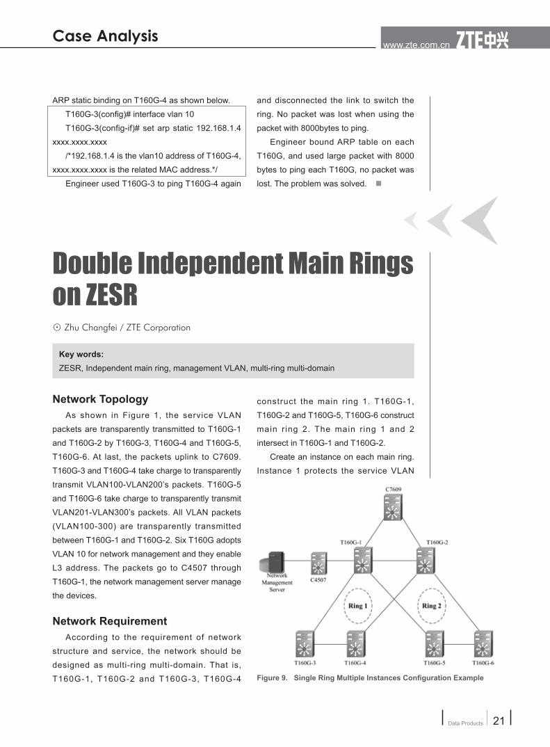
Network TopologyAs shown in Figure 1, the service VLAN
packets are transparently transmitted to T160G-1
and T160G-2 by T160G-3, T160G-4 and T160G-5,
T160G-6. At last, the packets uplink to C7609.
T160G-3 and T160G-4 take charge to transparently
transmit VLAN100-VLAN200’s packets. T160G-5
and T160G-6 take charge to transparently transmit
VLAN201-VLAN300’s packets. All VLAN packets
(VLAN100-300) are transparently transmitted
between T160G-1 and T160G-2. Six T160G adopts
VLAN 10 for network management and they enable
L3 address. The packets go to C4507 through
T160G-1, the network management server manage
the devices.
Network RequirementAccording to the requirement of network
structure and service, the network should be
designed as multi-ring multi-domain. That is,
T160G-1, T160G-2 and T160G-3, T160G-4
construct the main ring 1. T160G-1,
T160G-2 and T160G-5, T160G-6 construct
main r ing 2. The main r ing 1 and 2
intersect in T160G-1 and T160G-2.
Create an instance on each main ring.
Instance 1 protects the service VLAN
Figure 9. Single Ring Multiple Instances Configuration Example
and disconnected the link to switch the
ring. No packet was lost when using the
packet with 8000bytes to ping.
Engineer bound ARP table on each
T160G, and used large packet with 8000
bytes to ping each T160G, no packet was
lost. The problem was solved. ■

October 2008 Issue 134
Maintenance Experience22
100-200 of main ring 1.
Instance 2 protects the service VLAN
201-300 of main ring 2. This kind of
network structures is doable.
Considering the network management
VLAN 10 constructs a ring on each main
ring, VLAN also needs an instance to
provide protection.
Network AnalysisAccording to the working principle of
ZESR, two independent main rings can not
protect the same VLAN. That is, VLAN 10
is protected by the instance on the main
ring 1, so it can not be protected by the
instance on main ring 2 (It is not permitted
by actual configuration). However, VLAN
10 also construct a ring on main ring 2, if
it can not be protected, it will be a loop in
VLAN10. The following two methods can
be adopted to solve the problem.wThe VLAN 10 should be a ring on main
ring 1 but not on main ring 2. VLAN 10
is added into the protection instance on
main ring 1, but the packets of VLAN
10 will be not transparently transmitted
between T160G-5 and T160G-6 on
main ring 2. Therefore, VLAN 10
will not be a ring on main ring 2, but it is still
manageable.
However, the ring status will be unstable if this
configuration is adopted. The ring will be switched
continuously. Meanwhile, T160G-5 and T160G-6
can be managed by single l ink only, so the
redundancy protection does not take effect. This
method is not recommended to be used.● C rea te i ns tance 3 on each ma in r i ng
respectively. Instance 3 is used to manage
VLAN 10, and there are 3 domains now. A node
supports 4 domains at most. Too many domains
in a ring will decrease the convergence speed
of ring. (The convergence speed of a single
domain can reach 50ms, the convergence
speed of multi-domain is 50ms~200ms).
Therefore, this method is not suggested either.
SummaryThe main ring and secondary ring is adopted
as network structure to satisfy such requirement.
That is, a ring works as main ring, and another
ring works as secondary ring. These two rings
share one instance to protect all services and
management VLAN. The ring mode is multi ring
single domain.
Double main rings is not scientific in network
structure, so it is not suggested in actual scenario. ■
Address Superposition⊙Yang Fei / ZTE Corporation
Key words:BAS, address superposition, address pool, dial
Network TopologyAs shown in Figure 1, the users of dial-
up services connect to the UAS 10400 and
get on-line after passing the authentication
of the dial-up services.
Malfunction SituationDuring the service rush hour (20:00~21:00)

www.zte.com.cn
23Data Products
everyday, some users could dial successfully but
they failed to access to the Internet. The users
could ping the address of UAS 10400 successfully
but failed to ping other addresses. If the users
hung up and retried to dial for many times, maybe
they could access to the Internet. The problem did
not exist if it was not in service rush hour.
Malfunction AnalysisEngineers solved the problem before by
changing relevant cards. This time, engineers
changed the ports, slots and cards. But the
problem still existed.
Therefore, the problem may be caused by
routes. The engineers took the following steps.
1 . The eng inee rs execu ted the show subscribers active username <username>
command to find an IP address of a user with the
problem (192.168.1.20).2. The engineers logged into another device
and input the trace route 192.168.1.20 command.
3. The engineers logged into another device
and executed the trace route 192.168.1.1
command. The address 192.168.1.1 was the
interface address of the address pool that the user
address (192.168.1.20) was in.
The results of step 2 and 3 showed that the
address was not the address of the UAS 10400). It
was the address of the MA5200.
The engineers logged into the MA5200 and
checked the configuration. They found that
there was a network segment of user address
192.168.1.0/24 which was the same with the
network segment configured on the UAS 10400.
Besides, on the S8016 there was a static route that
designated the next hop of 192.168.1.0/24 to the
MA5200.
Due to the address superposition and there was
no route to the UAS 10400 from 192.168.1.0/24
on the S8016, when the users connecting to the
UAS 10400 obtained the addresses in network
segment 192.168.1.0/24, they failed to access to
the Internet.
SolutionThe engineers deleted the network
segment 192.168.1.0/24 from the address
pool on the MA5200, and then configured
the back route of 192.168.1.0/24 to the
UAS 10400 on the S8016. The problem
was solved.
Experience SummaryAccording to the address distribution
a lgo r i t hm on the UAS 10400 , t he
addresses in the pool are distributed
from top to bottom. The address pool
192.168.1.0/24 was the last but one,
therefore, it was used only during the
service rush hour.
When the users hung up and redialed,
if there were addresses in the pool on the
top released at that time, the users could
obtain the addresses to access to the
Internet normally. ■
Figure 1. Network Topology
October 2008 Issue 134
Maintenance Experience24
Switch CPU Utilization Ratio Abnormity⊙Zhang Fan / ZTE Corporation
Key words:3252, CPU, utilization ratio, ARP, ACL
Network TopologyOne ZXR10 3252 switch works as
the gateway and other two ZXR10 3252
switches work as the access switches. The
users use fixed IP addresses to access to
the network.
Malfunction SituationThe users had to wait for a long time
before they had an access to the Internet
successfully. Sometimes, they were failed
to have an access to the Internet.
The engineers logged into the gateway
switch to check the CPU utilization ratio.
They found that the CPU utilization ratio
was about 50% to 60%. When the users
pinged to the gateway, there was a long-
time delay.
Malfunction AnalysisTo find out the problem, the engineers
took the following steps.
1. The engineers logged into the
gateway switch to check the system
process information, as shown below.
3252#show taskinfo
NAME PRI STATUS MTICKS
Used(%)
------------- --- ------ ------ ------
Protocol 140 PEND 1
41.20
The result showed that the protocol
processes took up about 40% CPU
resources.
2. The engineers executed the show logging alarm command on the gateway switch to display
the alarm information, as shown below.
3252#show logging alarm
An alarm 21768 level 5 occurred at 23:36:01
04/01/2007 UTC sent by MCP %ACL PROTOCOL
PROTECT% Receive too many packets of
'arprequest' from port fei_1/1
An alarm 21768 level 5 occurred at 23:36:31
04/01/2007 UTC sent by MCP %ACL PROTOCOL
PROTECT% Receive too many packets of
'arprequest' from port fei_1/4
An alarm 21768 level 5 occurred at 23:36:31
04/01/2007 UTC sent by MCP %ACL PROTOCOL
PROTECT% Receive too many packets of
'arprequest' from port fei_1/1
……
The result showed that the switch received a lot
of ARP REQUEST messages.
3. The engineers execute the debug arp
command to check the ARP processes on the
switch, as shown below.
3252#debug arp
ARP debugging is on
18:55:48 IP ARP:req filtered src 192.168.11.175
000D.8769.079E, dst 192.168.222.41 wrong cable
vlan308
18:55:48 IP ARP:req filtered src 192.168.11.175
000D.8769.079E, dst 192.168.222.53 wrong cable
vlan308
18:55:48 IP ARP:req filtered src 192.168.11.175
000D.8769.079E, dst 192.168.222.116 wrong cable

www.zte.com.cn
25Data Products
vlan308
……
The result showed that there were some items
that could not be filtrated by the ARP source
filtration function.
According to the arp source-filtered rule, when
an interface receives an ARP message, the system
searches the route according to the source IP
address. If the route belongs to the local interface,
the device accepts the message; otherwise, the
device discards the message. By default, the ARP
source filtration function is enabled.
In this case, the gateway switch received a
lot of ARP REQUEST messages. The source IP
address of these ARP REQUEST messages was
not in the address range of its subnet. That is,
an illegal user sent the messages. Therefore, the
messages could not pass the ARP source filtration
and were discarded.
Since these messages were discarded,
the gateway switch should not process these
messages. Why did the CPU utilization ratio keep
high? It was because that the ARP source filtration
function was implemented by the software and
CPU took part in the judgment and calculation.
Therefore, these messages cost a lot of CPU
resources.
SolutionThe engineers used ACL to filtrate the illegal
messages, as shown below.
acl basic number 1
rule 1 deny 192.168.11.0 0.0.0.255 /*refuse
the packets with source IP addresses in network
segment 192.168.11.0/24 */
rule 2 permit any
!
Interface fei_1/1
ip access-group 1 0 in /*apply the ACL to
the interface*/
!
Interface fei_1/4
ip access-group 1 0 in
!
The ACL function is implemented by
hardware. When the interface received
the illegal messages, the messages were
discarded directly and did not cost the
CPU resources.
Experience SummaryWith the development of the network,
there are more and more network viruses.
In this case, a host of the user infected
the virus. The virus changed the source IP
address of the messages and sent them
to the switch. This affected the switch and
other users.
The anti-virus ACL can be applied to
interfaces to protect the host effectively.
A common anti-virus ACL configuration is
shown below.
acl extend number 101
rule 1 deny tcp any any eq 135
rule 2 deny tcp any any eq 139
rule 3 deny tcp any any eq 136
rule 4 deny tcp any any eq 137
rule 5 deny tcp any any eq 445
rule 6 deny tcp any any eq 5554
rule 7 deny tcp any any eq 9996
rule 8 deny tcp any any eq 1433
rule 9 deny tcp any any eq 1434
rule 10 deny udp any any eq 1433
rule 11 deny udp any any eq 1434
rule 12 deny udp any any eq 135
rule 13 deny udp any any eq 139
rule 14 deny udp any any eq 136
rule 15 deny udp any any eq 137
rule 16 deny udp any any eq 445
rule 17 deny udp any any eq 5554
rule 18 deny udp any any eq 9996
rule 19permit ip any any
! ■

October 2008 Issue 134
Maintenance Experience26
Malfunction SituationThe broadband devices such as
broadband switch, ADSL MODEM, optical
fiber transceiver are usually destroyed by
lighting stroke on thunderstorm season.
This problem should receive much concern
because it causes the communication
interruption and brings a lot of economic loss.
Malfunction AnalysisIt is well known that the lighting stroke
seeks a fast path to release electricity
by conductor. Broadband devices are
adopted by AC power supply, so the AC
power supply cable is the conductor.
For broadband switch, the outdoor
network cables are conductors, the lighting
stroke will be induct to switch by RJ45
port.
For ADSL MODEM, the outdoor cable
and user access line are conductors.
Optical transceiver is connected
with broadband switch by RJ45 port.
The lighting stroke will be inducted and
destroyed optical transceiver by RJ45 port
from broadband switch.
The reasons that broadband devices
are easily destroyed by lighting stroke can
be divided into the following four points.● CMOS application specific integrated
circuits are adopted by broadband
device largely. These integrated circuit
components are sensitive for induction.
Moreover, the conducted l ighting
stroke is stronger and faster. If the lighting
protection circuit is not designed well on port,
the broadband device is easily destroyed.● When the protection earthing terminal of
broadband device is well installed through
the excellent grounding device, it can provide
a release path for l ighting stroke. Some
constructors and maintenance staffs do not
pay attention to grounding installation, some
grounding devices are not installed completely,
and some device’s grounding resistances are
incompetent. ● Most of cable junction boxes do not have
lighting stroke protection.● During the process of laying cables on
residential district, some problems in regard to
the constructors' casual choice of cables, the
cable layout is jumbled and unreasonable. If
a cable is inducted by lighting stroke, a port or
broadband switch will be destroyed.
SolutionThe countermeasures of l ight ing stroke
protection on broadband devices can be divided
into the following five points.● Broadband device manufacturers should
analyze the induction path further and develop
the protection circuit.● The depar tmen t i n charge o f ne twork
construction should develop supervision cause
to assure engineering quality, especially for the
grounding device installation. The unqualified
engineering should be reformed and rectified
until it achieves the qualified level.
Lighting Stroke Damage on Broadband Device ⊙Zhu Shaohua/ China Telecom, Shishou Branch
Key words:lighting stroke, broadband switch, ADSL MODEM, optical transceiver, grounding, lightning
protection

www.zte.com.cn
27Data Products
A Tip of Batch Pasting on Hyper Terminal and SecureCRT⊙Bai Ping / ZTE Corporation
Key words:Hyper Terminal, secureCRT, batch pasting, input delay
Malfunction SituationWhen users perform batch pasting on router or
Ethernet switch by Hyper Terminal or SecureCRT, the
fault occurs. It causes the running configuration error,
and user needs to modify the configuration a lot.
The Hyper Terminal error is shown in Figure 1
The SecureCRT error is shown in Figure 2.
SolutionThe interval is too short when laptop or PC
sends command to router or Ethernet switch. The Figure 1. Hyper Terminal Error
Figure 2. SecureCRT Error Figure 3. Parameter Interface
● On the area where lighting occurs frequently,
the outdoor cable junction box should be
replaced with cable junction box with lighting
stroke protection. Make sure that the grounding
device buried is excellent.● The broadband switch lying on residential
district should be rebuilt designedly and step by
step.
● The department in charge of network
maintenance should arrange the staff
to examine all grounding condition
of broadband devices before each
thunderstorm season, and perform
electrical test on grounding resistance
of earthing cable. Make sure that
grounding resistance is qualified. ■

October 2008 Issue 134
Maintenance Experience28
devices can not response the command in time
that causes the fault occurs.
To solve this fault, modify the value of command
input delay on Hyper Terminal or SecureCRT.● Hyper Terminal
1. Click File → Parameters, an interface
appears as shown in Figure 3.
2. Click ASCII Setup, an interface appears as
shown in Figure 4. Enter 500 milliseconds into line
delay box.● SecureCRT
1. Click Options → Global Options →Category →Options →Advanced, enter 500 into <Line send
delay> box. That is, the line delay is modified into
500 milliseconds, as shown in Figure 5.
After modifying the line delay, the successful
effect of batch pasting about Hyper Terminal is
shown in Figure 6. The successful effect of batch
pasting about SecureCRT is shown in Figure 7.
SummaryWhen lots of commands need to paste, user
can modify the line delay of Hyper Terminal and
SecureCRT firstly, and then paste the commands
to Hyper Terminal or SecureCRT. This improves
the work greatly. ■
Figure 4. Line Delay Interface
Figure 5. SecureCRT Interface
Figure 6. Successful Batch Pasting on Hyper Terminal Figure 7. Successful Batch Pasting on SecureCRT

www.zte.com.cn
29GSM Products