Embed Size (px)
Citation preview

PREDICTION OF TYRE FRICTION
MUHAMAD MUHAIMIN BIN SHAARI
A Report in Partial Fulfillment of the Requirements for the Award of the Degree Of
Bachelor of Mechanical Engineering
FACULTY MECHANICAL ENGINEERING
UNIVERSITI MALAYSIA PAHANG
MAY 2009

v
ACKNOWLEDGEMENTS
First Of All I Would Like To Express My Fully Gratitude And Praise
‘Alhamdulilah’ To Allah The Almighty For Completion Of This Research. To My
Supervisor, Dr. Kumaran A/L Kadirgama, Thanks For All Your Guidance, Support
And Time For Me. Without Her Continued Support And Interest, This Thesis Would
Not Have Been The Same As Presented Here.
To My Beloved Family, Thank You For Your Support And Understanding. I
Acknowledge Without Endless Love And Relentless Support From My Family, I
Would Not Have Been Here. Father, Mother, Sister And Brothers, You All Have
Given Me The Inspirations And Encouragement Until These Days.
Last But Not Least, To My Course Mates, Thanks For The Supports And
Helps On My Research. I Could Never Repay And To All Whose I Not Mention
Here, I Appreciate Your Helps And Supports To Me.
vi
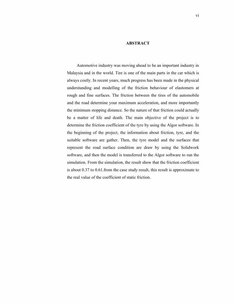
ABSTRACT
Automotive industry was moving ahead to be an important industry in
Malaysia and in the world. Tire is one of the main parts in the car which is
always costly. In recent years, much progress has been made in the physical
understanding and modelling of the friction behaviour of elastomers at
rough and fine surfaces. The friction between the tires of the automobile
and the road determine your maximum acceleration, and more importantly
the minimum stopping distance. So the nature of that friction could actually
be a matter of life and death. The main objective of the project is to
determine the friction coefficient of the tyre by using the Algor software. In
the beginning of the project, the information about friction, tyre, and the
suitable software are gather. Then, the tyre model and the surfaces that
represent the road surface condition are draw by using the Solidwork
software, and then the model is transferred to the Algor software to run the
simulation. From the simulation, the result show that the friction coefficient
is about 0.37 to 0.61.from the case study result, this result is approximate to
the real value of the coefficient of static friction.

vii
ABSTRAK
Industry automotif telah berkembang maju dan menjadi industri yang penting
di Malaysia dan seluruh dunia. Tayar merupakan benda asas yang penting pada
kenderaan. Pada masa sekarang, banyak kajian telah dibuat untuk mereka dan
memahami tentang sifat dan keadaan geseran antara elastromer dengan permukaan
kasar serta licin. Daya geseran antara tayar dan permukaan jalanraya manentukan
daya pecutan maksimum, dan yang penting sekali ialah jarak berhenti minimum bagi
sesebuah kenderaan. Oleh itu, sifat semulajadi geseran adalah berkait rapat antara
hidup dan mati. Objektif utama projek ini adalah untuk menentukan pemalar bagi
daya geseran tayar menggunakan perisian Algor. Bermula dengan mencari maklumat
tentang geseran, tayar sehingga kepada perisian yang sesuai digunakan. Selepas itu,
rekabentuk tayar dan permuka yang mewakili keadaan permukaan jalan di buat
menggunakan perisian Solidwork, kemudian dipindah ke perisian Algor untuk
menjalankan simulasi. Daripada simulasi tersebut, keputusan yang diperolehi bagi
pemalar geseran adalah 0.37 sehingga 0.61. daripada hasil tersebut, didapati
keputusan tersebut menyamai pemalar geseran yang sebenar yang diuji di makmal.
viii
TABLE OF CONTENTS
Page
TITLE PAGE i
SUPERVISOR DECLARATION ii
STUDENT DECLARATION iii
DEDICATION iv
ACKNOWLEGDEMENTS v
ABSTRACT vi
ABSTRAK vii
TABLE OF CONTENTS vii
LIST OF TABLES x
LIST OF FIGURE xi
CHAPTER 1 INTRODUCTION
1.1 Introduction 1
1.2 Project Background 1
1.3 Problem Statement 2
1.4 Project Objective 2
1.5 Project Scope 2
CHAPTER 2 LITERATURE REVIEW
2.1 Intorduction 3
2.2. Fundamental Of Tyre 3
2.3 Type Of Tyre
2.3.1 Summer Tyre 4
2.3.2 Winter Tyre 4
2.3.3 All Season Tyre 5
2.3.4 Slick Tyre 5
2.4 Friction 6
2.4.1 Information 8

ix
2.4.2 Law of Dry Friction 8
2.5 FINITE ELEMENT ANALYSIS 11
2.6 Other Research 12
CHAPTER 3 METHODOLOGY
3.1 Introduction 14
3.2 Find the Information 16
3.3 Design A Tyre Model and Plate Model and Simulation 16
CHAPTER 4 RESULTS AND DISCUSSION
4.1 Introduction 22
4.2 Calculation of X-Direction Force On Tire With Given
Weight and Acceleration 22
4.3 Analysis of Tyre Friction Using Different Surface 23
4.4 Summaries of The Tyre Friction Analysis 27
4.5 Results for the Simulation of the Tyre Friction 30
CHAPTER 5 CONCLUSION AND RECOMMENDATIONS
5.1 Conclusions 31
5.2 Recommendation And Future Works 32
REFERENCES 33
APPENDICES 34
x
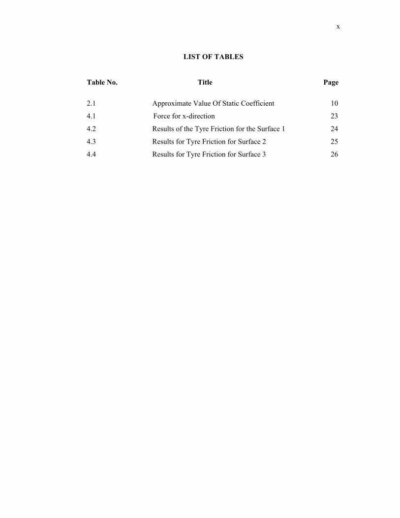
LIST OF TABLES
Table No. Title Page
2.1 Approximate Value Of Static Coefficient 10
4.1 Force for x-direction 23
4.2 Results of the Tyre Friction for the Surface 1 24
4.3 Results for Tyre Friction for Surface 2 25
4.4 Results for Tyre Friction for Surface 3 26
xi
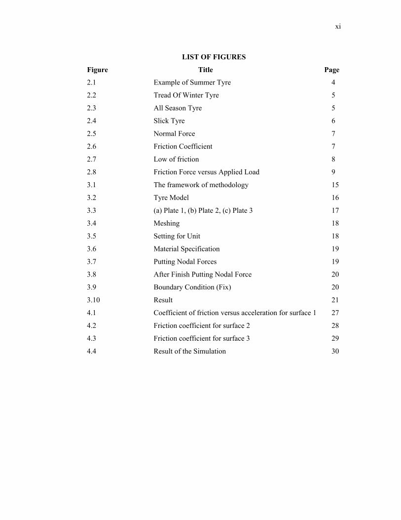
LIST OF FIGURES
Figure Title Page
2.1 Example of Summer Tyre 4
2.2 Tread Of Winter Tyre 5
2.3 All Season Tyre 5
2.4 Slick Tyre 6
2.5 Normal Force 7
2.6 Friction Coefficient 7
2.7 Low of friction 8
2.8 Friction Force versus Applied Load 9
3.1 The framework of methodology 15
3.2 Tyre Model 16
3.3 (a) Plate 1, (b) Plate 2, (c) Plate 3 17
3.4 Meshing 18
3.5 Setting for Unit 18
3.6 Material Specification 19
3.7 Putting Nodal Forces 19
3.8 After Finish Putting Nodal Force 20
3.9 Boundary Condition (Fix) 20
3.10 Result 21
4.1 Coefficient of friction versus acceleration for surface 1 27
4.2 Friction coefficient for surface 2 28
4.3 Friction coefficient for surface 3 29
4.4 Result of the Simulation 30
ABSTRACT
Automotive industry was moving ahead to be an important industry in
Malaysia and in the world. Tire is one of the main parts in the car which is
always costly. In recent years, much progress has been made in the physical
understanding and modelling of the friction behaviour of elastomers at rough
and fine surfaces. The friction between the tires of the automobile and the road
determine your maximum acceleration, and more importantly the minimum
stopping distance. So the nature of that friction could actually be a matter of
life and death. The main objective of the project is to determine the friction
coefficient of the tyre by using the Algor software. In the beginning of the
project, the information about friction, tyre, and the suitable software are
gather. Then, the tyre model and the surfaces that represent the road surface
condition are draw by using the Solidwork software, and then the model is
transferred to the Algor software to run the simulation. From the simulation,
the result show that the friction coefficient is about 0.37 to 0.61.from the case
study result, this result is approximate to the real value of the coefficient of
static friction.
ABSTRAK
Industry automotif telah berkembang maju dan menjadi industri yang penting di
Malaysia dan seluruh dunia. Tayar merupakan benda asas yang penting pada kenderaan.
Pada masa sekarang, banyak kajian telah dibuat untuk mereka dan memahami tentang
sifat dan keadaan geseran antara elastromer dengan permukaan kasar serta licin. Daya
geseran antara tayar dan permukaan jalanraya manentukan daya pecutan maksimum, dan
yang penting sekali ialah jarak berhenti minimum bagi sesebuah kenderaan. Oleh itu,
sifat semulajadi geseran adalah berkait rapat antara hidup dan mati. Objektif utama
projek ini adalah untuk menentukan pemalar bagi daya geseran tayar menggunakan
perisian Algor. Bermula dengan mencari maklumat tentang geseran, tayar sehingga
kepada perisian yang sesuai digunakan. Selepas itu, rekabentuk tayar dan permuka yang
mewakili keadaan permukaan jalan di buat menggunakan perisian Solidwork, kemudian
dipindah ke perisian Algor untuk menjalankan simulasi. Daripada simulasi tersebut,
keputusan yang diperolehi bagi pemalar geseran adalah 0.37 sehingga 0.61. daripada
hasil tersebut, didapati keputusan tersebut menyamai pemalar geseran yang sebenar yang
diuji di makmal.
CHAPTER 1
INTRODUCTION
1.1 INTRODUCTION
This chapter is discussed about the project background, the problem of the
project, the objective of the project and the project scope.
1.2 PROJECT BACKGROUND
Nowadays, tyre has many variant such as high traction, high speed, noiseless,
airless, tubeless, wide radial and long lasting.
The friction between the tires of your automobile and the road determine your
maximum acceleration and more importantly your minimum stopping distance. So the
nature of that friction could actually be a matter of life and death.
Many years of research and practice have led to tread designs for automobile
tires which offer good traction in a wide variety of conditions. The tread designs channel
water away from the bearing surfaces on wet roads to prevent the tendency to
hydroplaning.
]
2
1.3 PROBLEM STATEMENT
There are many way to predict the tyre friction, from calculation, simulation and
from experimental. Currently, researchers predict the tyre friction using manual
calculation and software. This project mainly concentrates the prediction of tyre friction
using Algor software with normal conditions.
1.4 PROJECT OBJECTIVE
The objectives of this project are:
1. To predict and study the tyre friction with FEA software
2. To improve knowledge about ALGOR software.
1.5 PROJECT SCOPE
In order to achieve the objectives the following scope of project are performed:
1. Literature review of the tyre, the friction, and the ALGOR software.
2. Gather information of the tyre
3. Design the tyre model and plate
4. Analysis of the current design using ALGOR software.
5. Determined the friction coefficient with certain calculation
CHAPTER 2
LITERATURE REVIEW
2.1 INTRODUCTION
In this chapter, there will be explanation on the definition of tyre and finite element usage for tyre simulation. This chapter will introduce the fundamental of the tyre and the basic type of tyre. In this chapter also explain about the finite element analysis that been use, that is ALGOR software.
2.2 FUNDAMENTAL OF TYRE
The earliest tyres were bands of iron placed on wooden wheels. It used on carts
and wagons. The tyre would be heated in a forge fire, placed over the wheel and
quenched causing the metal to contract and fit tightly on the wheel[2].
John Boyd Dunlop invented the first pneumatic tyre in 1887 for his son bicycle,
in order to prevent headaches of his son when riding bicycle on rough road[2].
The main material of pneumatic tyres is flexible elastromer material, such as
rubber. Fabric and wire are used to reinforce the tyre[2]
The tread is the part of tyre that contact to the road surface. It is design to
provide appropriate level of traction.
4
2.3 TYPE OF TYRE
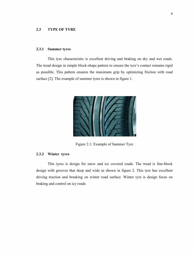
2.3.1 Summer tyres
This tyre characteristic is excellent driving and braking on dry and wet roads.
The tread design in simple block-shape pattern to ensure the tyre’s contact remains rigid
as possible. This pattern ensures the maximum grip by optimizing friction with road
surface [2]. The example of summer tyres is shown in figure 1.
Figure 2.1: Example of Summer Tyre
2.3.2 Winter tyres
This tyres is design for snow and ice covered roads. The tread is fine-block
design with grooves that deep and wide as shown in figure 2. This tyre has excellent
driving traction and breaking on winter road surface. Winter tyre is design focus on
braking and control on icy roads
5
Figure 2.2: Tread Of Winter Tyre
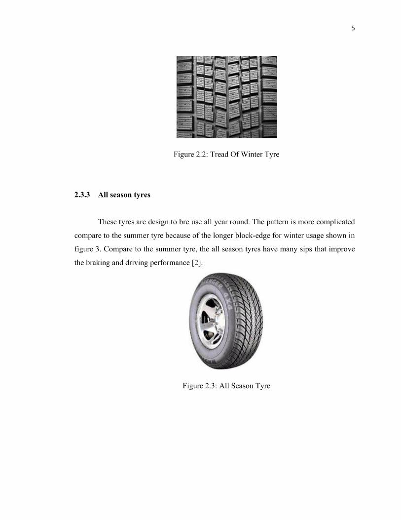
2.3.3 All season tyres
These tyres are design to bre use all year round. The pattern is more complicated
compare to the summer tyre because of the longer block-edge for winter usage shown in
figure 3. Compare to the summer tyre, the all season tyres have many sips that improve
the braking and driving performance [2].
Figure 2.3: All Season Tyre
6
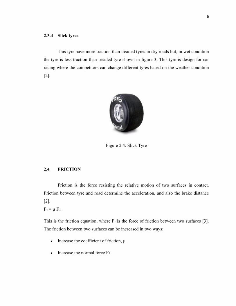
2.3.4 Slick tyres
This tyre have more traction than treaded tyres in dry roads but, in wet condition
the tyre is less traction than treaded tyre shown in figure 3. This tyre is design for car
racing where the competitors can change different tyres based on the weather condition
[2].
Figure 2.4: Slick Tyre
2.4 FRICTION
Friction is the force resisting the relative motion of two surfaces in contact.
Friction between tyre and road determine the acceleration, and also the brake distance
[2].
FF = µ F┴
This is the friction equation, where Ff is the force of friction between two surfaces [3].
The friction between two surfaces can be increased in two ways:
Increase the coefficient of friction, µ
Increase the normal force F┴
7
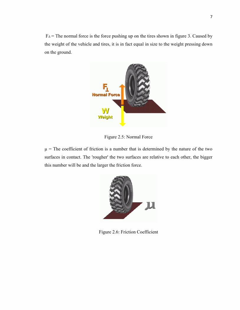
F┴ = The normal force is the force pushing up on the tires shown in figure 3. Caused by
the weight of the vehicle and tires, it is in fact equal in size to the weight pressing down
on the ground.
Figure 2.5: Normal Force
µ = The coefficient of friction is a number that is determined by the nature of the two
surfaces in contact. The 'rougher' the two surfaces are relative to each other, the bigger
this number will be and the larger the friction force.
Figure 2.6: Friction Coefficient
8
2.4.1 Information
Actually, no perfectly frictionless surface exists. When two surfaces are in
contact, tangential forces, called friction forces, will always develop if one attempts to
move surface with respect to each other. On the other hand, these friction forces are
limited in magnitude and will not prevent motion if sufficiently large forces are applied.
There are two types of friction; dry friction called coulomb friction and fluid
friction. Fluid friction develops between layers of fluid moving in different velocities.
This project is focusing about the dry friction.
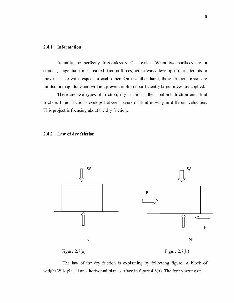
2.4.2 Law of dry friction
W W
P
F
N N
Figure 2.7(a) Figure 2.7(b)
The law of the dry friction is explaining by following figure. A block of
weight W is placed on a horizontal plane surface in figure 4.8(a). The forces acting on
9
the block are its weight and the reaction of the surface. Since the weight has no
horizontal component, the reaction is therefore normal to the surface and represented by
N. Now, that a horizontal force, P, is applied to the block in figure 4.8(b). If p is small,
the block will not move, some other horizontal force must therefore exist, which balance
P. This other force is the static friction force, F, which actually the resultant of the great
number forces acting over the entire surface of contact between block and the plane.
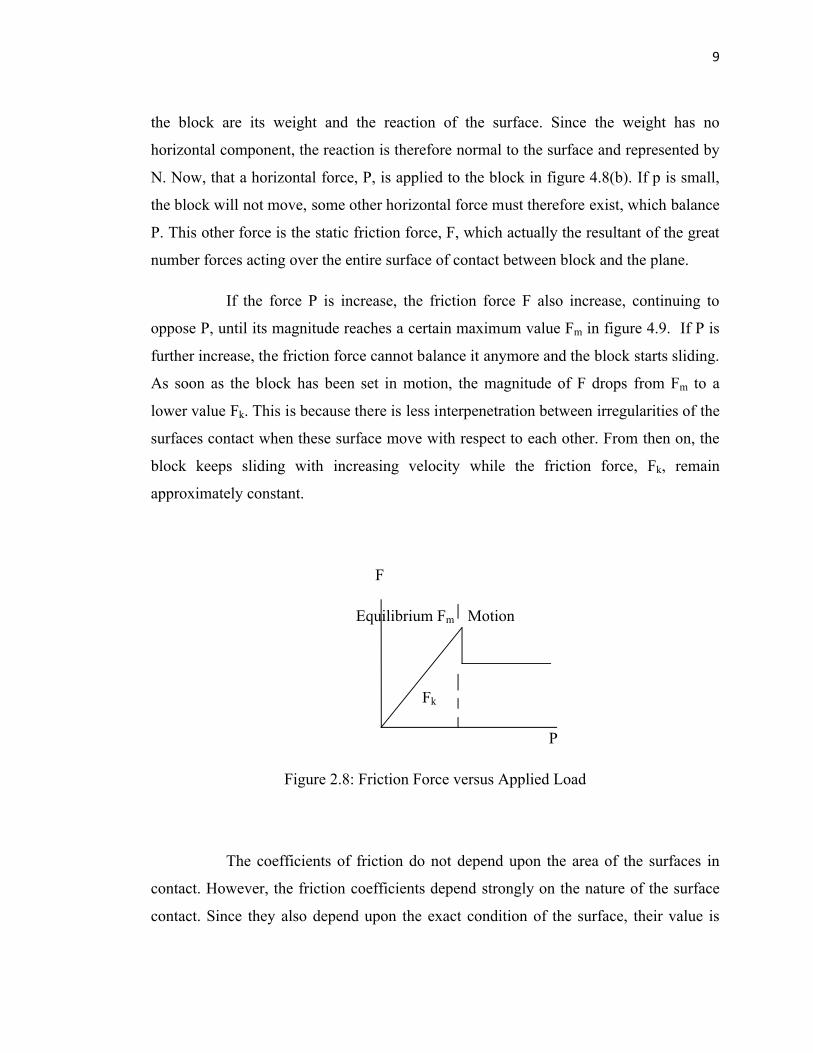
If the force P is increase, the friction force F also increase, continuing to
oppose P, until its magnitude reaches a certain maximum value Fm in figure 4.9. If P is
further increase, the friction force cannot balance it anymore and the block starts sliding.
As soon as the block has been set in motion, the magnitude of F drops from Fm to a
lower value Fk. This is because there is less interpenetration between irregularities of the
surfaces contact when these surface move with respect to each other. From then on, the
block keeps sliding with increasing velocity while the friction force, Fk, remain
approximately constant.
F
Equilibrium Fm Motion
Fk
P
Figure 2.8: Friction Force versus Applied Load
The coefficients of friction do not depend upon the area of the surfaces in
contact. However, the friction coefficients depend strongly on the nature of the surface
contact. Since they also depend upon the exact condition of the surface, their value is
10
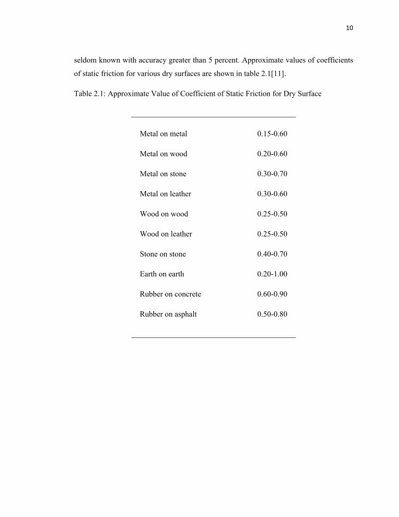
seldom known with accuracy greater than 5 percent. Approximate values of coefficients
of static friction for various dry surfaces are shown in table 2.1[11].
Table 2.1: Approximate Value of Coefficient of Static Friction for Dry Surface
Metal on metal 0.15-0.60
Metal on wood 0.20-0.60
Metal on stone 0.30-0.70
Metal on leather 0.30-0.60
Wood on wood 0.25-0.50
Wood on leather 0.25-0.50
Stone on stone 0.40-0.70
Earth on earth 0.20-1.00
Rubber on concrete 0.60-0.90
Rubber on asphalt 0.50-0.80
11
2.5 FINITE ELEMENT ANALYSIS
The finite element analysis (FEA) is a numerical technique for finding
approximate solutions of partial differential equations. Finite Element Analysis is based
on the premise that an approximate solution to any complex engineering problem can be
reached by subdividing the problem into smaller, more manageable (finite) elements.
Using finite elements, complex partial differential equations that describe the behavior
of structures can be reduced to a set of linear equations that can easily be solved using
the standard techniques of matrix algebra such as Euler’s method, Runge-Kutta and
else[3].
2.5.1 ALGOR
ALGOR is a general-purpose FEA software that developed by ALGOR Incorporated.
Many scientists and engineers used ALGOR software.
ALGOR is typically used to measure bending, the stress and strain, mechanical
contact, thermal fluid dynamic and couple and uncouple multiphysics. ALGOR’s library
of material model consist metal and alloy, plastics, glass, foams, elastromers, concrete
and also user-defines material.
ALGOR's element library depends on the geometry and type of analysis
performed. Its include 8 and 4 nodes brick, 8 and 4 nodes shell, brick, beam and trusses.
12
2.6 Other Research
2.6.1 Rubber friction, tread deformation and tyres term traction.
In this research, they research the role of rubber friction in previous tyre traction
with special emphasis on the load and velocity dependence of the friction coefficient. In
the first part, we present some basic concepts of contact mechanics of slipping previous
tyres and analyze the influence of energy dissipation due to tread deformation on the
friction force.
Then, apply a recently developed model of hysteresis and adhesion friction of
rubber on self-affine road surfaces for estimating the load dependence of the kinetic
friction coefficient in the contact area of slipping tyres [4].
2.6.2 Analysis of forced transient response for rotating tyres using REF models.
This paper presents a new approach for tyres dynamic analysis. By using this
method, transient response for rotating tyres under various loading situations can be
analyzed. The well-known model of ring on elastic foundations (REF) is utilized to
model tyre. The general forced solution of undamped inextensible vibration is derived
by the use of a modal expansion technique as well as Meirovitch modal analysis method.
Closed form transient response for the stationary constant point load case is obtained; for
the case of damped vibration, the response of rotating tyre is formulated by using the
first-order matrix perturbation theory together with Meirovitch modal analysis method.
The effects of damping on the tyre response are investigated. The developed method has
been validated by comparison with direct numerical integration results. Combined with a
contact or interface model, the proposed methodology can be used to model the tyre
dynamic responses under any given road profile [5].
2.6.3 Measurement and analysis of rolling tyre vibrations

13
This paper presents the measurement and analysis of rolling tyre vibrations due
to road impact excitations, such as from cobbled roads, junctions between concrete road
surface plates, railroad crossings. Vibrations of the tyre surface due to road impact
excitations cause noise radiation in the frequency band typically below 500 Hz. Tyre
vibration measurements with a laser Doppler vibrometer are performed on a test set-up
based on a tyre to tyre principle which allows highly repetitive and controllable impact
excitation tests under various realistic operating conditions. The influence on the
measured velocity of random noise, cross sensitivity and alignment errors is discussed.
An operational modal analysis technique is applied on sequential vibration
measurements to characterize the dynamic behavior of the rolling tyre. Comparison
between the operational modal parameters of the rolling tyres and the modal parameters
of the non-rolling tyre allows an assessment of the changes in dynamic behavior due to
rolling [6].
CHAPTER 3
METHODOLOGY
3.1 Introduction
This chapter describes the proposed framework for analysis of the tyre friction. The
framework of methodology is illustrated in figure 3.1. it consists of the following steps:
i. Find the information
ii. Design tyre model and surface
iii. Run simulation
iv. Collect the data
v. Analysis the data