Embed Size (px)
Citation preview

Predicting Emissions fromPredicting Emissions fromPrinted Circuit BoardsPrinted Circuit Boards
oror“The Quest for the Holy Grail”“The Quest for the Holy Grail”
Charles GrassoCharles GrassoStorageTekStorageTek
RMC EMC Symposium 1999

ContentsContents
n Prediction - The Holy Grailn Introduction to the Softwaren Description of Experimentn Modeling analysisn Data Comparisonn Conclusion
RMC EMC Symposium 1999

Prediction - The Holy Grail
nn The Product Designers Nightmare:The Product Designers Nightmare:––“Will my board pass the emissions test?”“Will my board pass the emissions test?”––“How big can the cooling holes be?”“How big can the cooling holes be?”––“How can I fix my EMC problem?”“How can I fix my EMC problem?”
nn Modeling Software can help.Modeling Software can help.
RMC EMC Symposium 1999

Ye Old EMC Design Strategy
Design itDesign itBuild itBuild itTest itTest it
Fix it -(cheaply?)Fix it -(cheaply?)Build new partsBuild new partsTest it AGAINTest it AGAIN
Ship it.Ship it.RMC EMC Symposium 1999

The NEW EMC Design Strategy
Design itDesign itSimulate itSimulate it
Build itBuild itTest it.Test it.Ship it.Ship it.
RMC EMC Symposium 1999

Field Solvers Can Save Timeand Money
nnUsing a solver we can createUsing a solver we can createmodels of components andmodels of components andperform subsystem and systemperform subsystem and systemlevel simulations as early aslevel simulations as early aspossible in the design cycle.possible in the design cycle.
RMC EMC Symposium 1999

What does a Field Solver do?What does a Field Solver do?
RMC EMC Symposium 1999
nn Solves Maxwell's Equations with specific Solves Maxwell's Equations with specificboundary conditions and defined materials.boundary conditions and defined materials.
nn Calculates and displays E, H fields. Calculates and displays E, H fields.nn Calculates and displays voltage and current Calculates and displays voltage and current
distributions.distributions.nn Calculates radiated fields. Calculates radiated fields.nn Calculates S-Parameters (allows use of Calculates S-Parameters (allows use of
physical physical structures as circuit elements)structures as circuit elements)
nn Performs automatic emissions test Performs automatic emissions test

Product Application
nn The benefits of Predictive Software:The benefits of Predictive Software:––Allows for analysis of sheet metal changes.Allows for analysis of sheet metal changes.––Analyze a printed wiring board before theAnalyze a printed wiring board before the
hardware is available.hardware is available.––Predict the emissions profile of a productPredict the emissions profile of a product
BEFORE the testBEFORE the test
RMC EMC Symposium 1999

Introduction to the Software
nn Ansoft HFSS (High Frequency StructureAnsoft HFSS (High Frequency StructureSimulator)Simulator)––Simulates arbitrary structures using FEMSimulates arbitrary structures using FEM––Full wave solver of Maxwell's EquationsFull wave solver of Maxwell's Equations––Can simulate an OATS experiment.Can simulate an OATS experiment.
RMC EMC Symposium 1999

Summary of FeaturesSummary of Features
nn Full-wave Finite Element MethodFull-wave Finite Element Methodnn Automatic Mesh Generation andAutomatic Mesh Generation and
Adaptive RefinementAdaptive Refinementnn Can compute near field and far fieldCan compute near field and far field
radiation patternsradiation patternsnn New Fast Frequency Sweep( New Fast Frequency Sweep(VerVer. 6). 6)
RMC EMC Symposium 1999

Adaptive MeshingAdaptive Meshing
Initial Mesh Final Mesh
2746 Tetrahedrons3 Adaptive Passes
1547 Tetrahedrons WR 90 waveguide f = 10 GHz∆s = 0.01
RMC EMC Symposium 1999

Ansoft HFSS Solver:Ansoft HFSS Solver:Adaptive SolutionAdaptive Solution
Create InitialMesh
Calculate ElectricFields
CalculateS-Parameters
DisplayS-Parameters
and Fields
Refine Mesh∆S Acceptable?No
Yes
Perform FrequencySweep
Initial
Second
Final

Calibration
nn Predictive Software:Predictive Software:––2D structures are easy to calibrate.2D structures are easy to calibrate.
nn MicrostripMicrostripnn Two wire structuresTwo wire structures
––How to calibrate the EME softwareHow to calibrate the EME softwarecapability?capability?
RMC EMC Symposium 1999

Description of Experiment
From: R.W. Dockey, Asymmetrical Mode Radiation from Multilayer Printed Circuit Boards EMC/ESD International Symposium, Denver 1992.
SMA ConnectorGround Plane
50 ohm trace 50 ohm resistorFR4 substrate
Side View
Top View
50 ohm trace 50 ohm resistor
RMC EMC Symposium 1999

The Physics of Radiation
Signal Source
Ground Plane
Signal Trace
Load
DifferentialCurrent Flow
Vg
Ls Lm
Ls Lm
RMC EMC Symposium 1999

Experiment Results
From: R.W. Dockey, Asymmetrical Mode Radiation from Multilayer Printed Circuit Boards EMC/ESD International Symposium, Denver 1992.
120mm x 280mm Standard PCB Without Cables
0
10
20
30
40
50
60
0 100 200 300 400 500 600 700 800 900 1000
Frequency (MHz)
Fiel
d S
tren
gth
(dB
uV/m
)
Field Strength
FCC Class B
RMC EMC Symposium 1999

The Experiment Model
RMC EMC Symposium 1999

Simulation Results
RMC EMC Symposium 1999

Data Comparison
nn Below PWB Cutoff Frequency -Below PWB Cutoff Frequency -––Data tracks very well in amplitude andData tracks very well in amplitude and
delta.delta.––At 200MHz:At 200MHz:
–– Measured data - 30dBuVMeasured data - 30dBuV–– Simulation - 27dBuVSimulation - 27dBuV–– ∆∆ Measured data - 12dB/100MHz Measured data - 12dB/100MHz–– ∆∆ Simulation - 13dB/100MHz Simulation - 13dB/100MHz
RMC EMC Symposium 1999
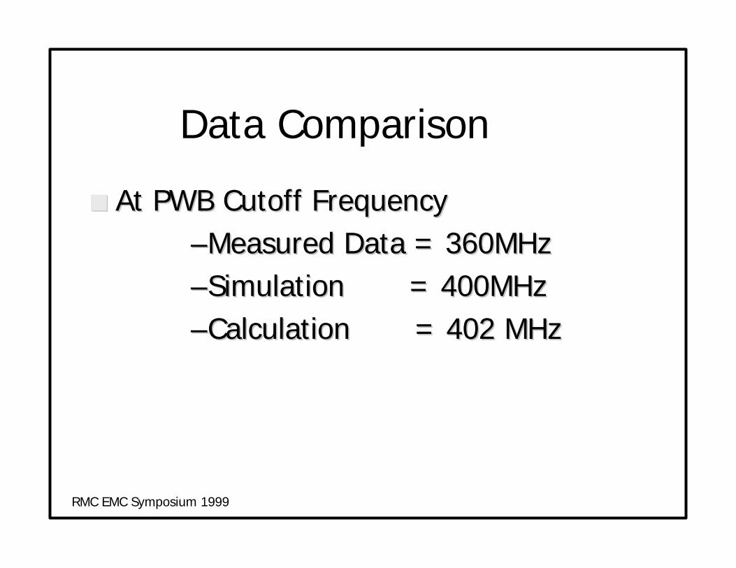
Data Comparison
nn At PWB Cutoff FrequencyAt PWB Cutoff Frequency––Measured Data = 360MHzMeasured Data = 360MHz––Simulation = 400MHzSimulation = 400MHz––Calculation = 402 MHzCalculation = 402 MHz
RMC EMC Symposium 1999

Data Comparison
nn At PWB Cutoff Frequency:At PWB Cutoff Frequency:––Actual Data = 47dBuVActual Data = 47dBuV––Simulation = 49dBuVSimulation = 49dBuV
nn Above PWB Cutoff Frequency -Above PWB Cutoff Frequency -––Actual data (@1000MHz) = 46dBuVActual data (@1000MHz) = 46dBuV––Simulation = 49dBuVSimulation = 49dBuV
RMC EMC Symposium 1999
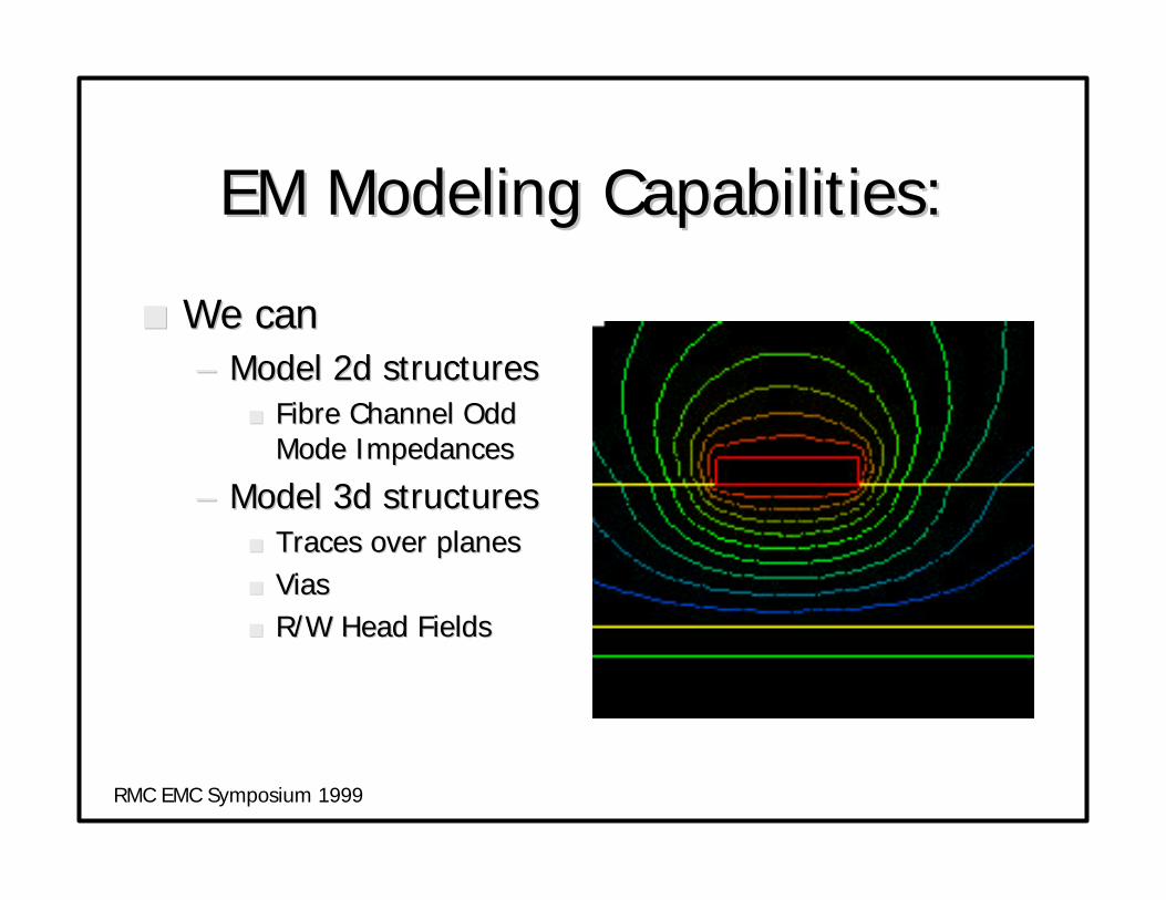
EM Modeling Capabilities:EM Modeling Capabilities:
nn We canWe can–– Model 2d structuresModel 2d structures
nn Fibre Channel OddFibre Channel OddMode ImpedancesMode Impedances
–– Model 3d structuresModel 3d structuresnn Traces over planesTraces over planesnn ViasViasnn R/W Head FieldsR/W Head Fields
RMC EMC Symposium 1999

EM Modeling Capabilities:EM Modeling Capabilities:
nn We will be able toWe will be able topredict radiatedpredict radiatedemissions from:emissions from:–– boardsboards–– enclosuresenclosures–– cablescables
RMC EMC Symposium 1999

ConclusionConclusion
nn Analysis software CAN be used toAnalysis software CAN be used topredict the emissions characteristics ofpredict the emissions characteristics ofa circuit board.a circuit board.
nn Calibration of the software is essentialCalibration of the software is essentialto ensure accurate application.to ensure accurate application.
RMC EMC Symposium 1999

Finally….
RMC EMC Symposium 1999