Embed Size (px)
Citation preview
Georgia Public Safety Training Center
Georgia Fire Academy
PRACTICALFIRE GROUNDHYDRAULICS
Student Manual
Copyright © 2018 Georgia Public Safety Training Center

1 Practical Fire Ground Hydraulics
Hydraulics
Hydraulics can be defined as "a branch of science that deals with the properties of water or other fluidsat rest and in motion". This is a broad subject. For our purposes we will deal only with those areas ofhydraulics that relate directly with fire ground operations. Fire Ground Hydraulics can be desribed as theapplication of the principles of hydraulics which allow us to efficiently and safely move water on the fire ground.
Water
Because we are dealing with water, we need to know a few things about it. Water is a compound consisting of2 atoms of Hydrogen combined with 1 atom of Oxygen. Water exists in it liquid state at temperatures between320F and 2120F. It is very abundant and readily accessible in most places on earth. PURE WATER is colorless,odorless, and tasteless. PURE WATER does not conduct electricity. We rarely, if ever, see pure water so,consider all water to be an excellent conductor of electricity.
Water freezes at 320F turning to a solid (ice) . Water boils at 2120F turning to a gas (steam). Water hasanother unique characteristic in that its point of greatest density is 400F. When both heated and cooled fromthis point water will expand.
The expansion of water below its freezing point is of greatest concern to us because this will cause pump pipingand housings to rupture. Water's expansion above its boiling point is used to our advantage when fightinginterior fires as this expansion will force smoke and products of combustion out of the fire area. Water'sexpansion increases as the temperature increases:
1700 times at 5000F2400 times at 12000F4200 times at 24000F
The characteristic that makes water ideally suited for pumping is for all practical purposes water cannot becompressed.
Pressure
Ordinarily one thinks of pressure as an application of force on one thing by another. Pressure can easily beconfused with force. Force is simply a measure of weight. Pressure is a measure of this weight (or force) perunit of area. We usually measure pressure in pounds per square inch (psi) or pounds per square foot.
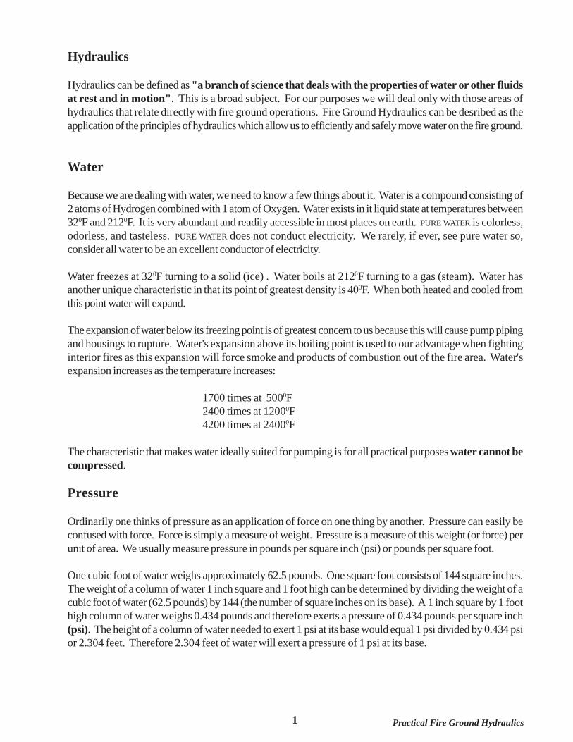
One cubic foot of water weighs approximately 62.5 pounds. One square foot consists of 144 square inches.The weight of a column of water 1 inch square and 1 foot high can be determined by dividing the weight of acubic foot of water (62.5 pounds) by 144 (the number of square inches on its base). A 1 inch square by 1 foothigh column of water weighs 0.434 pounds and therefore exerts a pressure of 0.434 pounds per square inch(psi). The height of a column of water needed to exert 1 psi at its base would equal 1 psi divided by 0.434 psior 2.304 feet. Therefore 2.304 feet of water will exert a pressure of 1 psi at its base.
2Practical Fire Ground Hydraulics
The speed at which water travels through hose is developed by pressure upon the water. The speed oftravel is referred to as velocity.
There are 6 basic principles that determine the action of pressure upon fluids. These principles should bestudied before the kinds of pressure are studied.
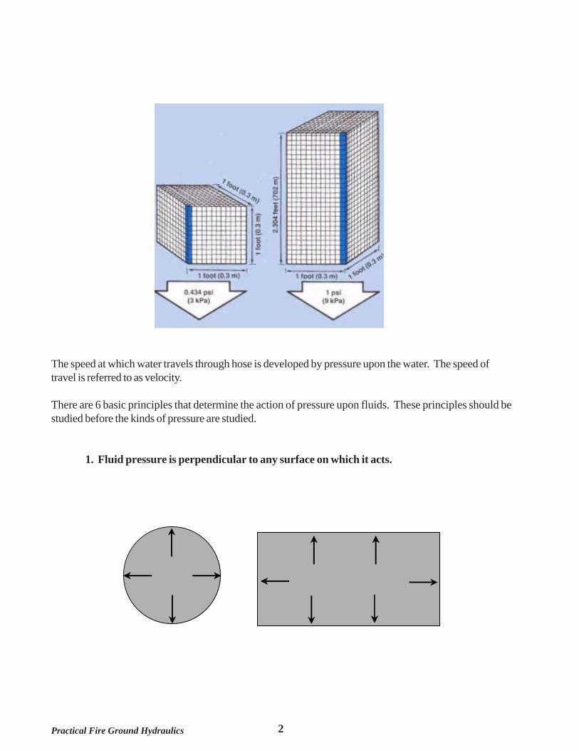
1. Fluid pressure is perpendicular to any surface on which it acts.
3 Practical Fire Ground Hydraulics
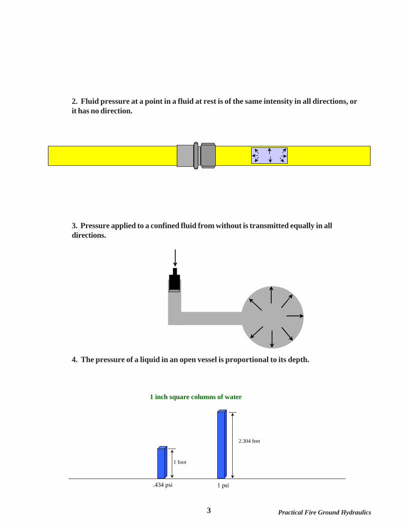
2. Fluid pressure at a point in a fluid at rest is of the same intensity in all directions, orit has no direction.
3. Pressure applied to a confined fluid from without is transmitted equally in alldirections.
4. The pressure of a liquid in an open vessel is proportional to its depth.
1 foot
2.304 feet
.434 psi 1 psi
1 inch square columns of water
4Practical Fire Ground Hydraulics
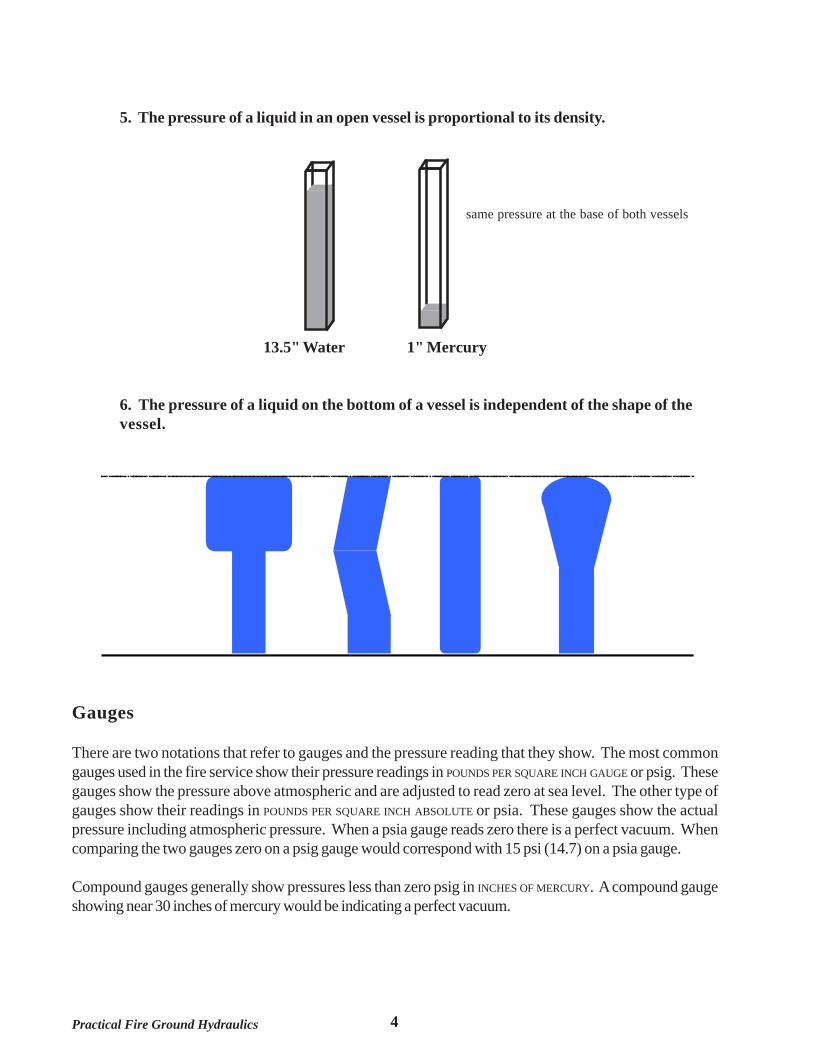
5. The pressure of a liquid in an open vessel is proportional to its density.
same pressure at the base of both vessels
13.5" Water 1" Mercury
6. The pressure of a liquid on the bottom of a vessel is independent of the shape of thevessel.
Gauges
There are two notations that refer to gauges and the pressure reading that they show. The most commongauges used in the fire service show their pressure readings in POUNDS PER SQUARE INCH GAUGE or psig. Thesegauges show the pressure above atmospheric and are adjusted to read zero at sea level. The other type ofgauges show their readings in POUNDS PER SQUARE INCH ABSOLUTE or psia. These gauges show the actualpressure including atmospheric pressure. When a psia gauge reads zero there is a perfect vacuum. Whencomparing the two gauges zero on a psig gauge would correspond with 15 psi (14.7) on a psia gauge.
Compound gauges generally show pressures less than zero psig in INCHES OF MERCURY. A compound gaugeshowing near 30 inches of mercury would be indicating a perfect vacuum.
5 Practical Fire Ground Hydraulics
Types of Pressure
There are several kinds of pressure acting upon fluids. The first of which is atmospheric pressure. Atmosphericpressure is the weight of air per square inch exerted on surfaces by the atmosphere. This pressure is greatestat lower altitudes. The pressure of the air at sea level is used as the standard for atmospheric pressure.Atmospheric pressure at sea level is 14.7 psia.
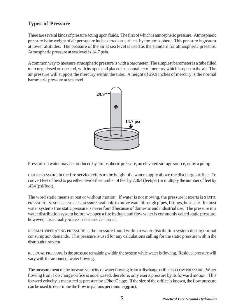
A common way to measure atmospheric pressure is with a barometer. The simplest barometer is a tube filledmercury, closed on one end, with its open end placed in a container of mercury which is open to the air. Theair pressure will support the mercury within the tube. A height of 29.9 inches of mercury is the normalbarometric pressure at sea level.
Pressure on water may be produced by atmospheric pressure, an elevated storage source, or by a pump.
HEAD PRESSURE in the fire service refers to the height of a water supply above the discharge orifice. Toconvert feet of head to psi either divide the number of feet by 2.304 (feet/psi) or multiply the number of feet by.434 (psi/foot).
The word static means at rest or without motion. If water is not moving, the pressure it exerts is STATICPRESSURE. STATIC PRESSURE is pressure available to move water through pipes, fittings, hose, etc. In mostwater systems true static pressure is never found because of domestic and industrial use. The pressure in awater distribution system before we open a fire hydrant and flow water is commonly called static pressure,however, it is actually NORMAL OPERATING PRESSURE.
NORMAL OPERATING PRESSURE is the pressure found within a water distribution system during normalconsumption demands. This pressure is used for any calculations calling for the static pressure within thedistribution system
RESIDUAL PRESSURE is the pressure remaining within the system while water is flowing. Residual pressure willvary with the amount of water flowing.
The measurement of the forward velocity of water flowing from a discharge orifice is FLOW PRESSURE. Waterflowing from a discharge orifice is not encased, therefore, only exerts pressure by its forward motion. Thisforward velocity is measured as pressure by a Pitot Gauge. If the size of the orifice is known, the flow pressurecan be used to determine the flow in gallons per minute (gpm).
29.9"-
14.7 psi

6Practical Fire Ground Hydraulics
If the water flowing through a hose or pipe is suddenly stopped, a tremendous increase in pressure results.This sudden increase in pressure is known as a WATER HAMMER and often can be heard as a distinct sharpclank sound similar to the sound of a hammer hitting a metal pipe. A water hammer can cause considerabledamage to water mains, fire hose, fire pumps and may injure fire fighters. Hydrants, nozzle shut-offs, valves,hose clamps and any other devices that control water flow should be operated slowly to prevent a waterhammer from occurring.
Pumps
The fire service has used two basic types of pumps. They are the POSITIVE DISPLACEMENT and the CENTRIFUGALpump. The positive displacement pumps have been replaced as the main pump on modern fire apparatus bythe centrifugal pump. Positive displacement pumps, however, are still needed because they have the ability topump air and centrifugal pumps do not have this ability. Positive displacement pumps are on most fire apparatusas the priming pump for the centrifugal pump. There are three types of positive displacement pumps: PISTON,ROTARY GEAR and ROTARY VANE.
PISTON PUMP
Piston Pumps
All piston pumps contain a piston that moves back and forth inside a cylinder. As the piston moves forward itcompresses the air within the cylinder creating a pressure higher than atmospheric which causes the dischargevalve to open and allow the air to be pushed out of the cylinder. When the cylinder reaches the end of thisstroke the pressure equalizes and the discharge valve closes. The piston then begins to move backward,creating a lower than atmospheric pressure within the cylinder causing the intake valve to open. Air will flowinto the cylinder from the intake side of the pump until the piston reaches the end of this stroke. The cycle isrepeated as the pump is operated. Once all the air is evacuated from the intake the pump will begin todischarge water and the pump is considered to be primed. The pump will then deliver a stream of water witheach stroke. This stream will pulse with each forward stroke of the pump.
The pump can be built to be double acting by the installation of additional intake and discharge valves in sucha way as to allow the pump to move water on both the forward and backward stroke. Another way that amore continuous stream of water can be maintained is to build the pump with multiple cylinders.
7 Practical Fire Ground Hydraulics
Since the pump cylinder contains a definite amount of water just that amount of water will be delivered witheach stroke of the piston. The output capacity of the pump is determined by the size of the cylinder. It is morepractical to build a multi-cylinder pump rather than just making the cylinder larger to increase the capacity ofthe pump.
Rotary Pumps
Rotary type pumps are the simplest of all fire apparatus pumps from the standpoint of design. Most of therotary type positive displacement pumps in use today are either of the rotary gear or rotary vane construction.
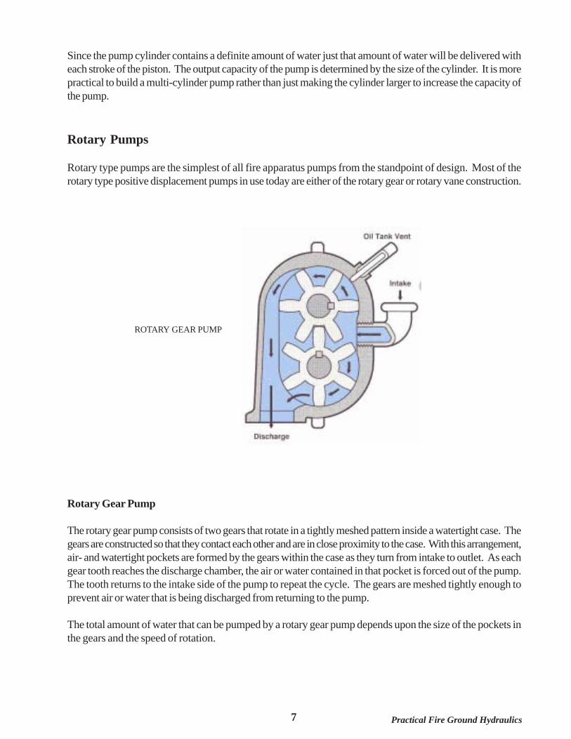
ROTARY GEAR PUMP
Rotary Gear Pump
The rotary gear pump consists of two gears that rotate in a tightly meshed pattern inside a watertight case. Thegears are constructed so that they contact each other and are in close proximity to the case. With this arrangement,air- and watertight pockets are formed by the gears within the case as they turn from intake to outlet. As eachgear tooth reaches the discharge chamber, the air or water contained in that pocket is forced out of the pump.The tooth returns to the intake side of the pump to repeat the cycle. The gears are meshed tightly enough toprevent air or water that is being discharged from returning to the pump.
The total amount of water that can be pumped by a rotary gear pump depends upon the size of the pockets inthe gears and the speed of rotation.
8Practical Fire Ground Hydraulics
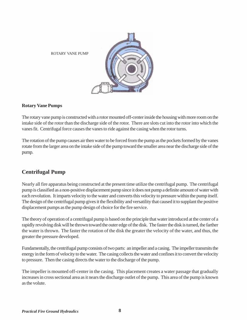
ROTARY VANE PUMP
Rotary Vane Pumps
The rotary vane pump is constructed with a rotor mounted off-center inside the housing with more room on theintake side of the rotor than the discharge side of the rotor. There are slots cut into the rotor into which thevanes fit. Centrifugal force causes the vanes to ride against the casing when the rotor turns.
The rotation of the pump causes air then water to be forced from the pump as the pockets formed by the vanesrotate from the larger area on the intake side of the pump toward the smaller area near the discharge side of thepump.
Centrifugal Pump
Nearly all fire apparatus being constructed at the present time utilize the centrifugal pump. The centrifugalpump is classified as a non-positive displacement pump since it does not pump a definite amount of water witheach revolution. It imparts velocity to the water and converts this velocity to pressure within the pump itself.The design of the centrifugal pump gives it the flexibility and versatility that caused it to supplant the positivedisplacement pumps as the pump design of choice for the fire service.
The theory of operation of a centrifugal pump is based on the principle that water introduced at the center of arapidly revolving disk will be thrown toward the outer edge of the disk. The faster the disk is turned, the fartherthe water is thrown. The faster the rotation of the disk the greater the velocity of the water, and thus, thegreater the pressure developed.
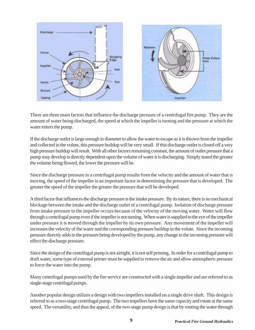
Fundamentally, the centrifugal pump consists of two parts: an impeller and a casing. The impeller transmits theenergy in the form of velocity to the water. The casing collects the water and confines it to convert the velocityto pressure. Then the casing directs the water to the discharge of the pump.
The impeller is mounted off-center in the casing. This placement creates a water passage that graduallyincreases in cross sectional area as it nears the discharge outlet of the pump. This area of the pump is knownas the volute.
9 Practical Fire Ground Hydraulics
There are three main factors that influence the discharge pressure of a centrifugal fire pump. They are theamount of water being discharged, the speed at which the impeller is turning and the pressure at which thewater enters the pump.
If the discharge outlet is large enough in diameter to allow the water to escape as it is thrown from the impellerand collected in the volute, this pressure buildup will be very small. If this discharge outlet is closed off a veryhigh pressure buildup will result. With all other factors remaining constant, the amount of outlet pressure that apump may develop is directly dependent upon the volume of water it is discharging. Simply stated the greaterthe volume being flowed, the lower the pressure will be.
Since the discharge pressure in a centrifugal pump results from the velocity and the amount of water that ismoving, the speed of the impeller is an important factor in determining the pressure that is developed. Thegreater the speed of the impeller the greater the pressure that will be developed.
A third factor that influences the discharge pressure is the intake pressure. By its nature, there is no mechanicalblockage between the intake and the discharge outlet of a centrifugal pump. Isolation of discharge pressurefrom intake pressure in the impeller occurs because of the velocity of the moving water. Water will flowthrough a centrifugal pump even if the impeller is not turning. When water is supplied to the eye of the impellerunder pressure it is moved through the impeller by its own pressure. Any movement of the impeller willincreases the velocity of the water and the corresponding pressure buildup in the volute. Since the incomingpressure directly adds to the pressure being developed by the pump, any change in the incoming pressure willeffect the discharge pressure.
Since the design of the centrifugal pump is not airtight, it is not self priming. In order for a centrifugal pump todraft water, some type of external primer must be supplied to remove the air and allow atmospheric pressureto force the water into the pump.
Many centrifugal pumps used by the fire service are constructed with a single impeller and are referred to assingle-stage centrifugal pumps.
Another popular design utilizes a design with two impellers installed on a single drive shaft. This design isreferred to as a two-stage centrifugal pump. The two impellers have the same capacity and rotate at the samespeed. The versatility, and thus the appeal, of the two-stage pump design is that by routing the water through

10Practical Fire Ground Hydraulics
the pump in different ways either the full rated capacity of the pump can be delivered or a much higher thannormal pressure can be developed. A TRANSFER VALVE is employed to control the routing of water within thepump.
When the transfer valve is in the volume (or parallel)configuration, each of the impellers receives water fromthe intake side of the pump and deliver the water into the discharge side of the pump. The volume of eachimpeller's output is added together to provide the total flow of the pump. The pressure of the pump is the sameat the discharge of each impeller.
When the transfer valve is in the pressure (or series) configuration, one impeller receives its water from theintake side of the pump, imparts pressure to the water and delivers the water to the intake of the secondimpeller. The second impeller receives this water, imparts the same amount of pressure on the water as the firstimpeller and delivers the water to the discharge side of the pump. The pressure developed by the pump is thesum of the pressure imparted by each impeller. The flow is limited to the output of the second impeller only.
As a rule of thumb, two-stage pumps may be operated in the pressure configuration until 50% of the ratedcapacity is being pumped. Once the pump is called upon to deliver more than 50% of its rated capacity thetransfer valve should be operated to the volume configuration. Should there be any question which configurationto be in, operate the pump in the volume configuration. This will allow the pump to develop any needed flowup to its capacity.
If the flow drops below 50% of rated capacity the transfer valve may be operated to return the pump to thepressure configuration. For safety reasons the transfer valve should not be operated from volume to pressureat a net pump pressure of over 50 psi. If necessary the pump's speed should be reduced to 50 psi or less netpump pressure while the transfer valve is operated. This change over should be coordinated with attack crewssince there may be a reduction in nozzle effectiveness while operating the transfer valve.
The portion of the discharge pressure that the pump is producing is the NET PUMP PRESSURE. When operatingfrom a positive pressure source, such as a hydrant, the net pump pressure is the discharge pressure less theintake pressure. When operating from a draft, the net pump pressure is the discharge pressure plus the suctionpressure.
Regardless of the number of impellers they have CLASS A fire pumps are designed to a specific set of guidelines.These guidelines prescribe the percentage of the pump's capacity that must be delivered at 150 psi, 200 psiand 250 psi net pump pressure.
Class A pumps are designed to pump:
100% of its rated capacity at 150 psi 70% of its rated capacity at 200 psi 50% of its rated capacity at 250 psi
11 Practical Fire Ground Hydraulics
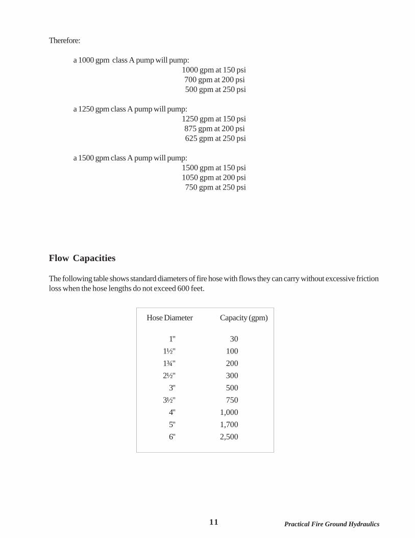
Therefore:
a 1000 gpm class A pump will pump:1000 gpm at 150 psi 700 gpm at 200 psi 500 gpm at 250 psi
a 1250 gpm class A pump will pump:1250 gpm at 150 psi 875 gpm at 200 psi 625 gpm at 250 psi
a 1500 gpm class A pump will pump:1500 gpm at 150 psi1050 gpm at 200 psi 750 gpm at 250 psi
Flow Capacities
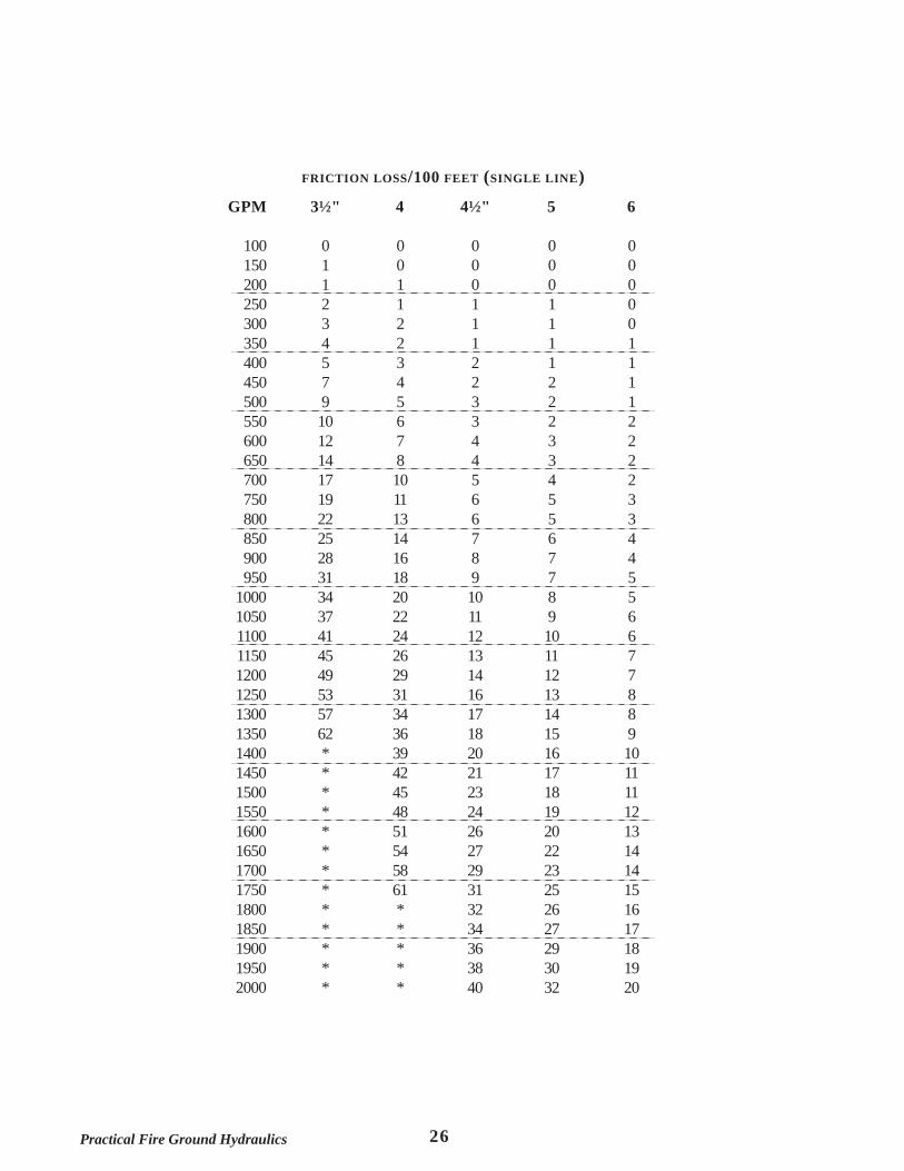
The following table shows standard diameters of fire hose with flows they can carry without excessive frictionloss when the hose lengths do not exceed 600 feet.
Hose Diameter Capacity (gpm)
1" 301½" 1001¾" 2002½" 300
3" 5003½" 750
4" 1,0005" 1,7006" 2,500

12Practical Fire Ground Hydraulics
Hose for Fire Attack
The size of hose chosen for a particular fire attack is dictated by the flow required for fire control andextinguishment. The following table lists some common flow requirements and the hose generally used tosupply those flows.
Flow Hose Size
up to 40 gpm ¾-1" booster line
40-125 gpm 1½" hand line
95-200 gpm 1¾" hand line
125-350 gpm 2½" hand line
350 + gpm multiple 2½-3" lines (Master stream)
Nozzles
There are basically two types of nozzles. They are SOLID STREAM (also called smooth bore or solid bore) andFOG or COMBINATION. The basic design of the nozzle types are the same for both hand line and master streamapplications. Since the basic design of the nozzle determines how the nozzle creates its water flow pattern, wewill discuss the design of each type of nozzle and the resulting pattern for each.
Solid Stream Nozzles
This nozzle is designed so that the waterway tapers as it approaches the outlet until it reaches a point approximately1-1½ times the nozzle diameter from the outlet. At this point the waterway becomes a cylindrical bore of thenozzle diameter. The stream of water leaving the nozzle is a cylinder the diameter of the nozzle bore. The flowpressure of a smooth bore nozzle is measured with a Pitot gauge in order to determine its flow in gallons perminute. The correct placement of the Pitot gauge inlet is the center of the stream at a point one-half thediameter of the nozzle bore from the end of the nozzle.
The gpm flow of smooth bore nozzles can be adjusted by increasing and decreasing the flow pressure at thedischarge orifice of the nozzle. Smooth bore nozzles used on hand lines are generally operated at a nozzlepressure of 50 psi. Nozzle pressures for smooth bore hand lines of less than 35-40 psi generally produce
13 Practical Fire Ground Hydraulics
ineffective streams. Nozzle pressures of more than 65 psi on smooth bore hand lines produce a stream that isextremely difficult to handle with reduced reach. Smooth bore nozzles used on master stream devices aregenerally operated at a nozzle pressure of 80 psi.
Fog Nozzles
Nozzles commonly referred to as fog nozzles produce a variety of patterns for the application of water. Thesepatterns are produced by two basic types of fog nozzles. These types of fog nozzles are the IMPINGINGSTREAM and PERIPHERY DEFLECTED STREAM nozzle.
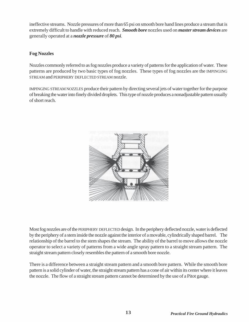
IMPINGING STREAM NOZZLES produce their pattern by directing several jets of water together for the purposeof breaking the water into finely divided droplets. This type of nozzle produces a nonadjustable pattern usuallyof short reach.
IMPINGING STREAM NOZZLE
Most fog nozzles are of the PERIPHERY DEFLECTED design. In the periphery deflected nozzle, water is deflectedby the periphery of a stem inside the nozzle against the interior of a movable, cylindrically shaped barrel. Therelationship of the barrel to the stem shapes the stream. The ability of the barrel to move allows the nozzleoperator to select a variety of patterns from a wide angle spray pattern to a straight stream pattern. Thestraight stream pattern closely resembles the pattern of a smooth bore nozzle.
There is a difference between a straight stream pattern and a smooth bore pattern. While the smooth borepattern is a solid cylinder of water, the straight stream pattern has a cone of air within its center where it leavesthe nozzle. The flow of a straight stream pattern cannot be determined by the use of a Pitot gauge.

14Practical Fire Ground Hydraulics
PERIPHERY DEFLECTED STREAM NOZZLES
Types of Periphery Deflected Fog Nozzles
The flow of a NON-CONSTANT GALLONAGE nozzle changes when the pattern is changed. These nozzles flowtheir rated capacity at the 300 spray pattern at 100psi nozzle pressure. A straight stream pattern will producea flow of 15% less than that of the 300 spray pattern. The wide angle spray pattern will produce a flow of 15%greater than that of the 300 spray pattern.
The CONSTANT GALLONAGE nozzle will discharge the same rate of flow at any pattern selected.
An ADJUSTABLE GALLONAGE nozzle is a constant gallonage nozzle with a refinement. The adjustable gallonagenozzle has a selector device added which allows the nozzle operator to select one of the various flow settingsto operate the nozzle.
AUTOMATIC NOZZLES, like constant flow nozzles, have no change in flow when the pattern is changed. Theirflow is determined by the pressure at which the water reaches the nozzle. The greater the pressure at which thewater flows through the nozzle, the more the pressure regulating stem will open. The greater the openingcreated by the stem, the greater the flow from the nozzle. As the pressure entering the nozzle is reduced, thestem will reduce the opening through which the water is flowing and thus maintain a good pattern at thisreduced flow.
Fog nozzles of the types other than automatic nozzles generally designed to operate at a nozzle pressure of100psi. Some manufacturers recently have begun to offer nozzles that are designed to operate at a nozzlepressure of 75psi.
15 Practical Fire Ground Hydraulics
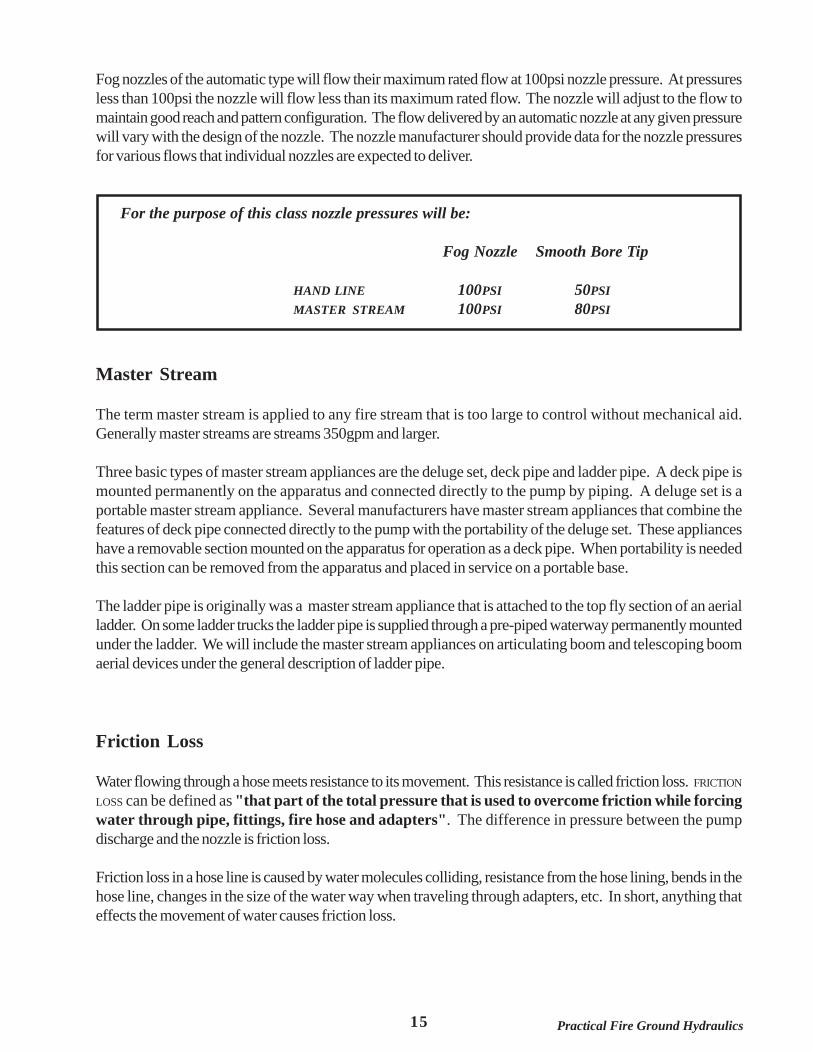
Fog nozzles of the automatic type will flow their maximum rated flow at 100psi nozzle pressure. At pressuresless than 100psi the nozzle will flow less than its maximum rated flow. The nozzle will adjust to the flow tomaintain good reach and pattern configuration. The flow delivered by an automatic nozzle at any given pressurewill vary with the design of the nozzle. The nozzle manufacturer should provide data for the nozzle pressuresfor various flows that individual nozzles are expected to deliver.
For the purpose of this class nozzle pressures will be:
Fog Nozzle Smooth Bore Tip
HAND LINE 100PSI 50PSIMASTER STREAM 100PSI 80PSI
Master Stream
The term master stream is applied to any fire stream that is too large to control without mechanical aid.Generally master streams are streams 350gpm and larger.
Three basic types of master stream appliances are the deluge set, deck pipe and ladder pipe. A deck pipe ismounted permanently on the apparatus and connected directly to the pump by piping. A deluge set is aportable master stream appliance. Several manufacturers have master stream appliances that combine thefeatures of deck pipe connected directly to the pump with the portability of the deluge set. These applianceshave a removable section mounted on the apparatus for operation as a deck pipe. When portability is neededthis section can be removed from the apparatus and placed in service on a portable base.
The ladder pipe is originally was a master stream appliance that is attached to the top fly section of an aerialladder. On some ladder trucks the ladder pipe is supplied through a pre-piped waterway permanently mountedunder the ladder. We will include the master stream appliances on articulating boom and telescoping boomaerial devices under the general description of ladder pipe.
Friction Loss
Water flowing through a hose meets resistance to its movement. This resistance is called friction loss. FRICTION
LOSS can be defined as "that part of the total pressure that is used to overcome friction while forcingwater through pipe, fittings, fire hose and adapters". The difference in pressure between the pumpdischarge and the nozzle is friction loss.
Friction loss in a hose line is caused by water molecules colliding, resistance from the hose lining, bends in thehose line, changes in the size of the water way when traveling through adapters, etc. In short, anything thateffects the movement of water causes friction loss.
16Practical Fire Ground Hydraulics
To reduce friction loss any of the following may be done:
avoid using old hose with rough linings replace crushed couplings use adapters only when necessary use gaskets of the proper size keep hose lines as short as possible eliminate sharp bends/kinks in hose lines keep nozzles and valves fully open when possible when flow must be increased use larger or multiple hose lines
There are two principles of friction loss that we will discuss in this course.
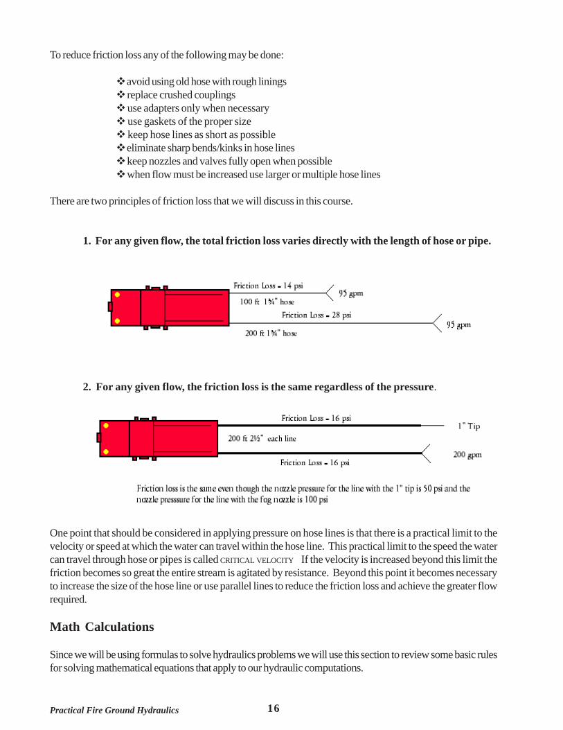
1. For any given flow, the total friction loss varies directly with the length of hose or pipe.
2. For any given flow, the friction loss is the same regardless of the pressure.
One point that should be considered in applying pressure on hose lines is that there is a practical limit to thevelocity or speed at which the water can travel within the hose line. This practical limit to the speed the watercan travel through hose or pipes is called CRITICAL VELOCITY If the velocity is increased beyond this limit thefriction becomes so great the entire stream is agitated by resistance. Beyond this point it becomes necessaryto increase the size of the hose line or use parallel lines to reduce the friction loss and achieve the greater flowrequired.
Math Calculations
Since we will be using formulas to solve hydraulics problems we will use this section to review some basic rulesfor solving mathematical equations that apply to our hydraulic computations.
17 Practical Fire Ground Hydraulics
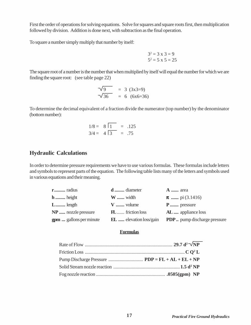
First the order of operations for solving equations. Solve for squares and square roots first, then multiplicationfollowed by division. Addition is done next, with subtraction as the final operation.
To square a number simply multiply that number by itself:
32 = 3 x 3 = 952 = 5 x 5 = 25
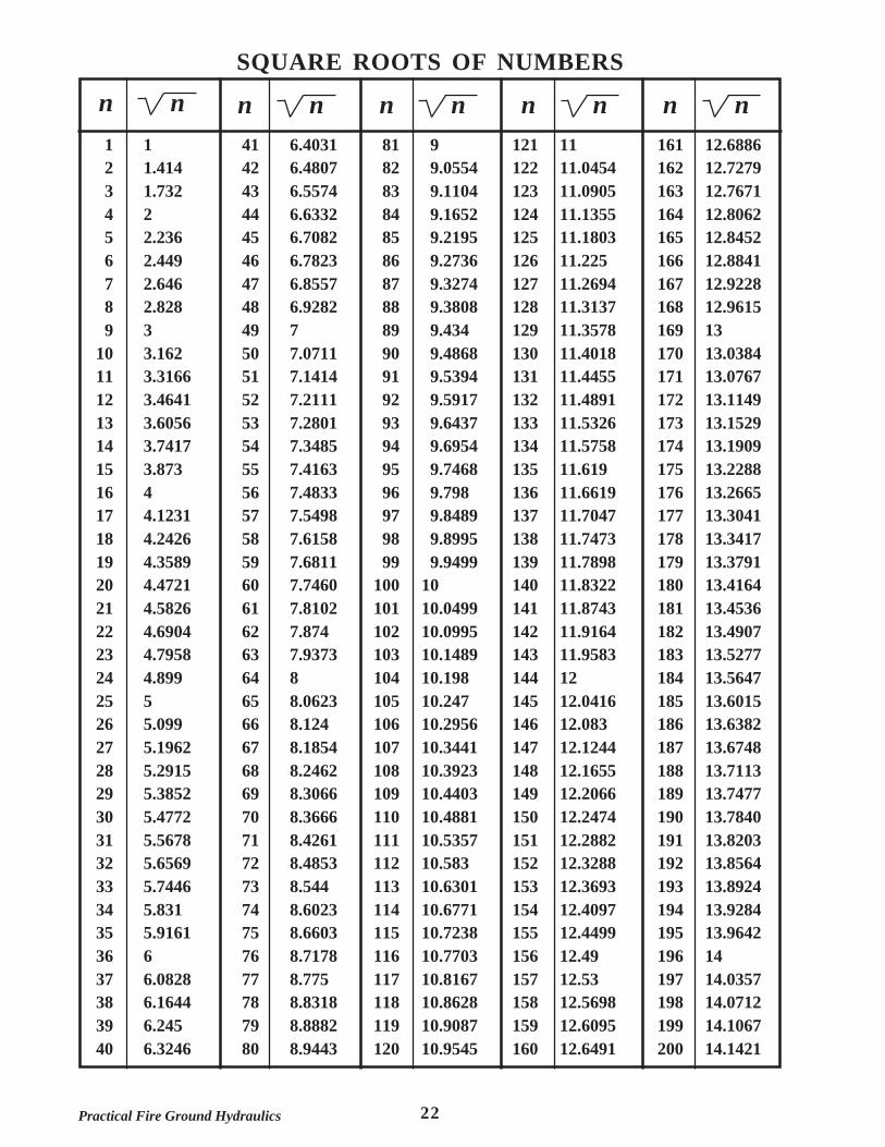
The square root of a number is the number that when multiplied by itself will equal the number for which we arefinding the square root: (see table page 22)
9 = 3 (3x3=9)36 = 6 (6x6=36)
To determine the decimal equivalent of a fraction divide the numerator (top number) by the denominator(bottom number):
1/8 = 8 1 = .1253/4 = 4 3 = .75
Hydraulic Calculations
In order to determine pressure requirements we have to use various formulas. These formulas include lettersand symbols to represent parts of the equation. The following table lists many of the letters and symbols usedin various equations and their meaning.
r......... radius d ........ diameter A ...... areah ........ height W ...... width πππππ .............................. pi (3.1416)L........ length V ....... volume P ....... pressureNP ..... nozzle pressure FL ...... friction loss AL .... appliance lossgpm ... gallons per minute EL ..... elevation loss/gain PDP.. pump discharge pressure
Formulas
Rate of Flow ....................................................................... 29.7 d2 NPFriction Loss ................................................................................. C Q2 LPump Discharge Pressure ............................ PDP = FL + AL + EL + NPSolid Stream nozzle reaction ......................................................1.5 d2 NPFog nozzle reaction ........................................................ .0505(gpm) NP
18Practical Fire Ground Hydraulics
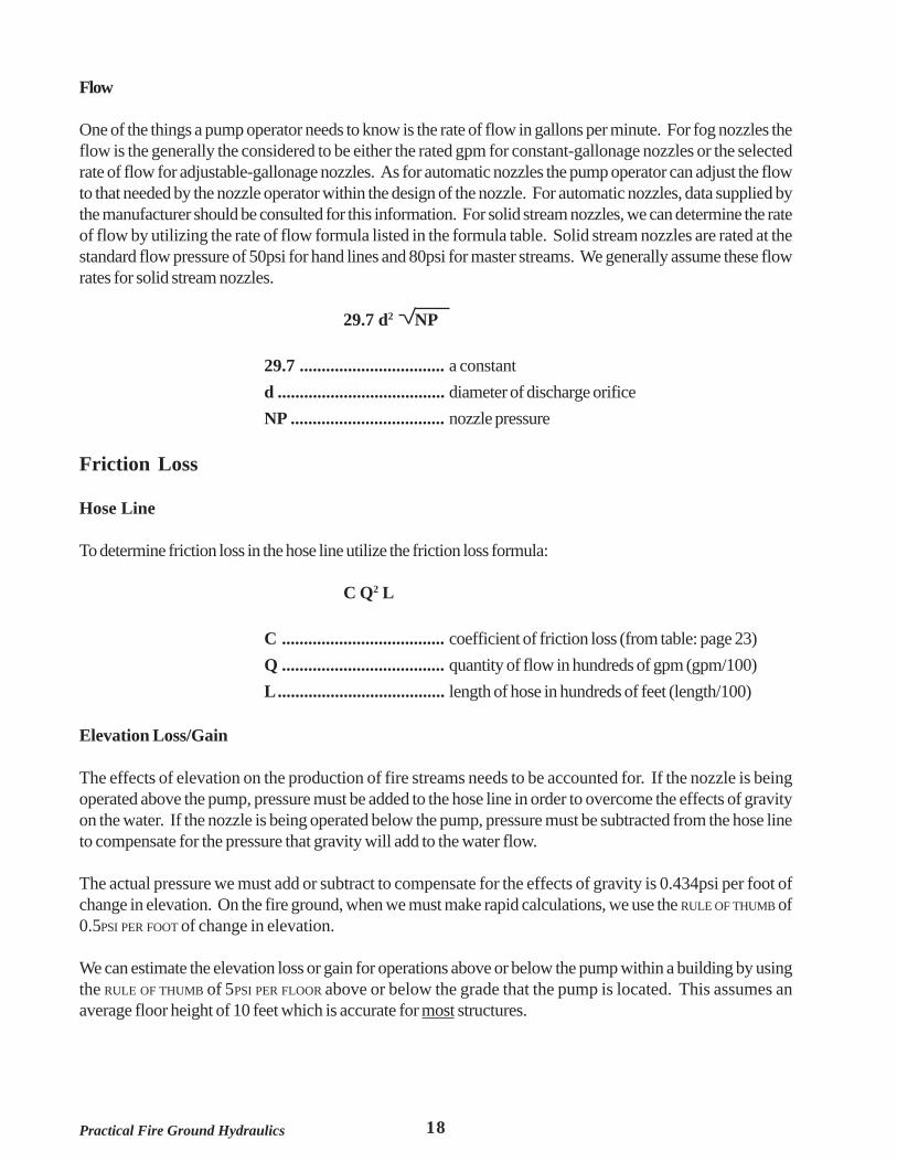
Flow
One of the things a pump operator needs to know is the rate of flow in gallons per minute. For fog nozzles theflow is the generally the considered to be either the rated gpm for constant-gallonage nozzles or the selectedrate of flow for adjustable-gallonage nozzles. As for automatic nozzles the pump operator can adjust the flowto that needed by the nozzle operator within the design of the nozzle. For automatic nozzles, data supplied bythe manufacturer should be consulted for this information. For solid stream nozzles, we can determine the rateof flow by utilizing the rate of flow formula listed in the formula table. Solid stream nozzles are rated at thestandard flow pressure of 50psi for hand lines and 80psi for master streams. We generally assume these flowrates for solid stream nozzles.
29.7 d2 NP
29.7 ................................. a constantd ...................................... diameter of discharge orificeNP ................................... nozzle pressure
Friction Loss
Hose Line
To determine friction loss in the hose line utilize the friction loss formula:
C Q2 L
C ..................................... coefficient of friction loss (from table: page 23)Q ..................................... quantity of flow in hundreds of gpm (gpm/100)L...................................... length of hose in hundreds of feet (length/100)
Elevation Loss/Gain
The effects of elevation on the production of fire streams needs to be accounted for. If the nozzle is beingoperated above the pump, pressure must be added to the hose line in order to overcome the effects of gravityon the water. If the nozzle is being operated below the pump, pressure must be subtracted from the hose lineto compensate for the pressure that gravity will add to the water flow.
The actual pressure we must add or subtract to compensate for the effects of gravity is 0.434psi per foot ofchange in elevation. On the fire ground, when we must make rapid calculations, we use the RULE OF THUMB of0.5PSI PER FOOT of change in elevation.
We can estimate the elevation loss or gain for operations above or below the pump within a building by usingthe RULE OF THUMB of 5PSI PER FLOOR above or below the grade that the pump is located. This assumes anaverage floor height of 10 feet which is accurate for most structures.
19 Practical Fire Ground Hydraulics
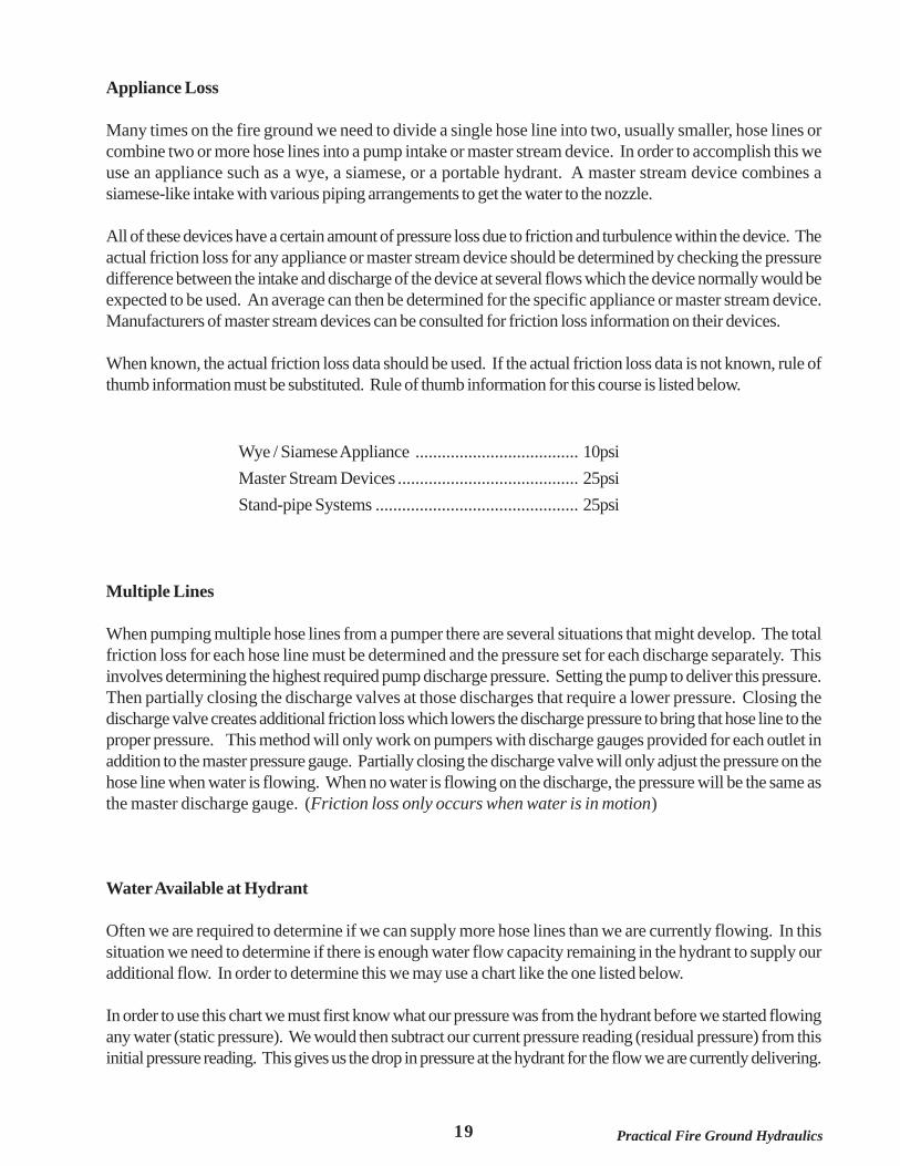
Appliance Loss
Many times on the fire ground we need to divide a single hose line into two, usually smaller, hose lines orcombine two or more hose lines into a pump intake or master stream device. In order to accomplish this weuse an appliance such as a wye, a siamese, or a portable hydrant. A master stream device combines asiamese-like intake with various piping arrangements to get the water to the nozzle.
All of these devices have a certain amount of pressure loss due to friction and turbulence within the device. Theactual friction loss for any appliance or master stream device should be determined by checking the pressuredifference between the intake and discharge of the device at several flows which the device normally would beexpected to be used. An average can then be determined for the specific appliance or master stream device.Manufacturers of master stream devices can be consulted for friction loss information on their devices.
When known, the actual friction loss data should be used. If the actual friction loss data is not known, rule ofthumb information must be substituted. Rule of thumb information for this course is listed below.
Wye / Siamese Appliance ..................................... 10psiMaster Stream Devices ......................................... 25psiStand-pipe Systems .............................................. 25psi
Multiple Lines
When pumping multiple hose lines from a pumper there are several situations that might develop. The totalfriction loss for each hose line must be determined and the pressure set for each discharge separately. Thisinvolves determining the highest required pump discharge pressure. Setting the pump to deliver this pressure.Then partially closing the discharge valves at those discharges that require a lower pressure. Closing thedischarge valve creates additional friction loss which lowers the discharge pressure to bring that hose line to theproper pressure. This method will only work on pumpers with discharge gauges provided for each outlet inaddition to the master pressure gauge. Partially closing the discharge valve will only adjust the pressure on thehose line when water is flowing. When no water is flowing on the discharge, the pressure will be the same asthe master discharge gauge. (Friction loss only occurs when water is in motion)
Water Available at Hydrant
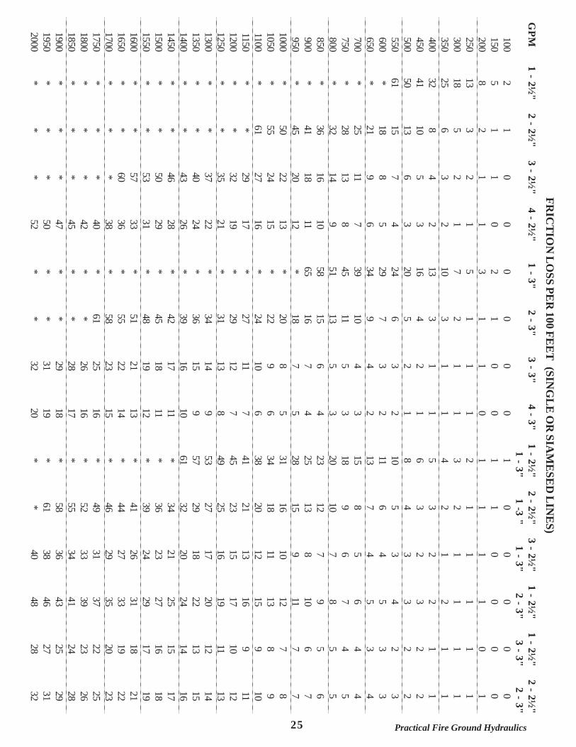
Often we are required to determine if we can supply more hose lines than we are currently flowing. In thissituation we need to determine if there is enough water flow capacity remaining in the hydrant to supply ouradditional flow. In order to determine this we may use a chart like the one listed below.
In order to use this chart we must first know what our pressure was from the hydrant before we started flowingany water (static pressure). We would then subtract our current pressure reading (residual pressure) from thisinitial pressure reading. This gives us the drop in pressure at the hydrant for the flow we are currently delivering.
20Practical Fire Ground Hydraulics
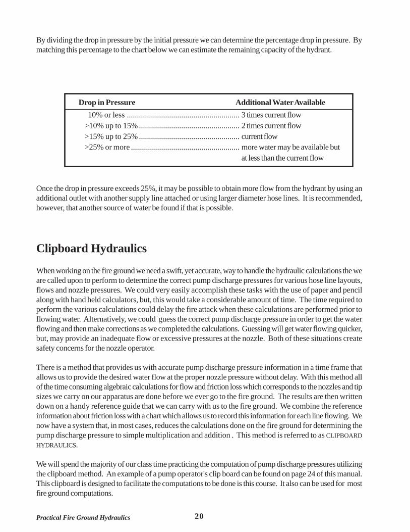
By dividing the drop in pressure by the initial pressure we can determine the percentage drop in pressure. Bymatching this percentage to the chart below we can estimate the remaining capacity of the hydrant.
Drop in Pressure Additional Water Available 10% or less ........................................................ 3 times current flow>10% up to 15% .................................................. 2 times current flow>15% up to 25% .................................................. current flow>25% or more ...................................................... more water may be available but
at less than the current flow
Once the drop in pressure exceeds 25%, it may be possible to obtain more flow from the hydrant by using anadditional outlet with another supply line attached or using larger diameter hose lines. It is recommended,however, that another source of water be found if that is possible.
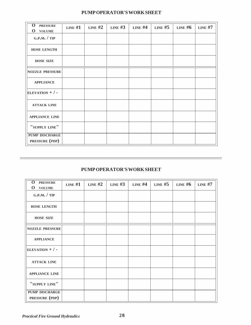
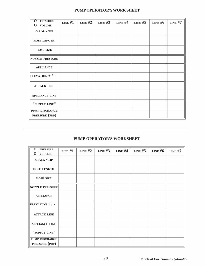
Clipboard Hydraulics
When working on the fire ground we need a swift, yet accurate, way to handle the hydraulic calculations the weare called upon to perform to determine the correct pump discharge pressures for various hose line layouts,flows and nozzle pressures. We could very easily accomplish these tasks with the use of paper and pencilalong with hand held calculators, but, this would take a considerable amount of time. The time required toperform the various calculations could delay the fire attack when these calculations are performed prior toflowing water. Alternatively, we could guess the correct pump discharge pressure in order to get the waterflowing and then make corrections as we completed the calculations. Guessing will get water flowing quicker,but, may provide an inadequate flow or excessive pressures at the nozzle. Both of these situations createsafety concerns for the nozzle operator.
There is a method that provides us with accurate pump discharge pressure information in a time frame thatallows us to provide the desired water flow at the proper nozzle pressure without delay. With this method allof the time consuming algebraic calculations for flow and friction loss which corresponds to the nozzles and tipsizes we carry on our apparatus are done before we ever go to the fire ground. The results are then writtendown on a handy reference guide that we can carry with us to the fire ground. We combine the referenceinformation about friction loss with a chart which allows us to record this information for each line flowing. Wenow have a system that, in most cases, reduces the calculations done on the fire ground for determining thepump discharge pressure to simple multiplication and addition . This method is referred to as CLIPBOARDHYDRAULICS.
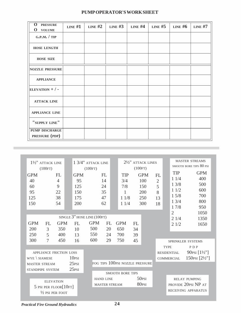
We will spend the majority of our class time practicing the computation of pump discharge pressures utilizingthe clipboard method. An example of a pump operator's clip board can be found on page 24 of this manual.This clipboard is designed to facilitate the computations to be done is this course. It also can be used for mostfire ground computations.

21 Practical Fire Ground Hydraulics
One of the advantages of this system is that the clipboard can be customized to fit the needs of individual firedepartments or even to specific pumpers within the department. For example, notes about standard flowsand/or operating pressures for pre-connected hose line or special devices can be included along with theinformation about friction losses on the clipboard. Essentially any information deemed necessary by a firedepartment can be detailed on the clipboard.
The clipboard on page 24 is divided into 2 main sections. The upper half of the clipboard is the portion wherepump discharge pressure information is recorded. This half is subdivided into an section where the hose layoutis described as to flow, size and length of hose lines along with an section to write down the figures to determinepump discharge pressure. The lower half is the portion in which friction loss data for common flows and hosesizes, as well as, reminders about appliance friction loss and special devices or situations.
22Practical Fire Ground Hydraulics
1 12 1.4143 1.7324 25 2.2366 2.4497 2.6468 2.8289 3
10 3.16211 3.316612 3.464113 3.605614 3.741715 3.87316 417 4.123118 4.242619 4.358920 4.472121 4.582622 4.690423 4.795824 4.89925 526 5.09927 5.196228 5.291529 5.385230 5.477231 5.567832 5.656933 5.744634 5.83135 5.916136 637 6.082838 6.164439 6.24540 6.3246
41 6.403142 6.480743 6.557444 6.633245 6.708246 6.782347 6.855748 6.928249 750 7.071151 7.141452 7.211153 7.280154 7.348555 7.416356 7.483357 7.549858 7.615859 7.681160 7.746061 7.810262 7.87463 7.937364 865 8.062366 8.12467 8.185468 8.246269 8.306670 8.366671 8.426172 8.485373 8.54474 8.602375 8.660376 8.717877 8.77578 8.831879 8.888280 8.9443
81 982 9.055483 9.110484 9.165285 9.219586 9.273687 9.327488 9.380889 9.43490 9.486891 9.539492 9.591793 9.643794 9.695495 9.746896 9.79897 9.848998 9.899599 9.9499
100 10101 10.0499102 10.0995103 10.1489104 10.198105 10.247106 10.2956107 10.3441108 10.3923109 10.4403110 10.4881111 10.5357112 10.583113 10.6301114 10.6771115 10.7238116 10.7703117 10.8167118 10.8628119 10.9087120 10.9545
121 11122 11.0454123 11.0905124 11.1355125 11.1803126 11.225127 11.2694128 11.3137129 11.3578130 11.4018131 11.4455132 11.4891133 11.5326134 11.5758135 11.619136 11.6619137 11.7047138 11.7473139 11.7898140 11.8322141 11.8743142 11.9164143 11.9583144 12145 12.0416146 12.083147 12.1244148 12.1655149 12.2066150 12.2474151 12.2882152 12.3288153 12.3693154 12.4097155 12.4499156 12.49157 12.53158 12.5698159 12.6095160 12.6491
161 12.6886162 12.7279163 12.7671164 12.8062165 12.8452166 12.8841167 12.9228168 12.9615169 13170 13.0384171 13.0767172 13.1149173 13.1529174 13.1909175 13.2288176 13.2665177 13.3041178 13.3417179 13.3791180 13.4164181 13.4536182 13.4907183 13.5277184 13.5647185 13.6015186 13.6382187 13.6748188 13.7113189 13.7477190 13.7840191 13.8203192 13.8564193 13.8924194 13.9284195 13.9642196 14197 14.0357198 14.0712199 14.1067200 14.1421
n n n n n n n n n n
SQUARE ROOTS OF NUMBERS
23 Practical Fire Ground Hydraulics
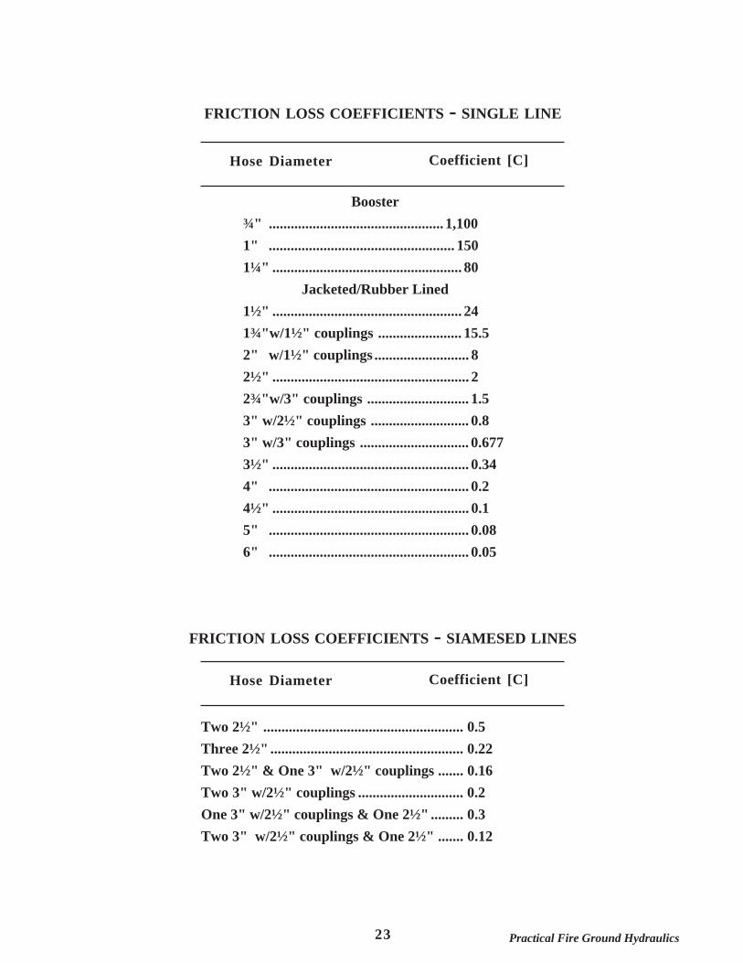
FRICTION LOSS COEFFICIENTS - SINGLE LINE
Booster¾" ................................................ 1,1001" ................................................... 1501¼" .................................................... 80
Jacketed/Rubber Lined1½" .................................................... 241¾"w/1½" couplings ....................... 15.52" w/1½" couplings .......................... 82½" ...................................................... 22¾"w/3" couplings ............................ 1.53" w/2½" couplings ........................... 0.83" w/3" couplings .............................. 0.6773½" ...................................................... 0.344" ....................................................... 0.24½" ...................................................... 0.15" ....................................................... 0.086" ....................................................... 0.05
Hose Diameter Coefficient [C]
FRICTION LOSS COEFFICIENTS - SIAMESED LINES
Hose Diameter Coefficient [C]
Two 2½" ....................................................... 0.5Three 2½" ..................................................... 0.22Two 2½" & One 3" w/2½" couplings ....... 0.16Two 3" w/2½" couplings ............................. 0.2One 3" w/2½" couplings & One 2½" ......... 0.3Two 3" w/2½" couplings & One 2½" ....... 0.12
24Practical Fire Ground Hydraulics
PUMP OPERATOR'S WORK SHEET
G.P.M. / TIP
HOSE LENGTH
HOSE SIZE
ELEVATION + / -
APPLIANCE LINE
ATTACK LINE
"SUPPLY LINE"PUMP DISCHARGE
PRESSURE (PDP)
APPLIANCE
NOZZLE PRESSURE
LINE #1 LINE #2 LINE #7LINE #6LINE #4LINE #3 LINE #5O PRESSURE
O VOLUME
1½" ATTACK LINE
(100FT)
GPM 40 60 95 125 150
FL 4 9223854
1 3/4" ATTACK LINE
(100FT)
GPM 95 125 150 175 200
MASTER STREAMSSMOOTH BORE TIPS 80 PSI
TIP1 1/41 3/81 1/21 5/81 3/41 7/822 1/42 1/2
GPM 400 500 600 700 800 950 1050 1350 1650
GPM 100 150 200 250 300
TIP 3/4 7/8 11 1/81 1/4
FL 2 5 81318
2½" ATTACK LINES
(100FT)
FL1424354762
SINGLE 3" HOSE LINE (100FT)GPM 200 250 300
FL 3 5 7
GPM 350 400 450
FL101316
GPM 500 550 600
FL202429
GPM 650 700 750
FL343945
APPLIANCE FRICTION LOSS
WYE \ SIAMESE 10PSI
MASTER STREAM 25PSI
STANDPIPE SYSTEM 25PSISMOOTH BORE TIPS
HAND LINE 50PSI
MASTER STREAM 80PSI
FOG TIPS 100PSI NOZZLE PRESSURE
RELAY PUMPING
PROVIDE 20PSI NP AT
RECEIVING APPARATUS
SPRINKLER SYSTEMS
TYPE P D PRESIDENTIAL 90PSI [1½"]COMMERCIAL 150PSI [2½"]
ELEVATION
5 PSI PER FLOOR[10FT]½ PSI PER FOOT
25 Practical Fire Ground Hydraulics
FRIC
TIO
N L
OSS PE
R 100 FE
ET
(SING
LE
OR
SIAM
ESE
D L
INE
S)G
PM100150200250300350400450500550600650700750800850900950
100010501100115012001250130013501400145015001550160016501700175018001850190019502000
1 - 3"
02357101316202429343945515865**********************
4 - 2½"
001112233456789101112131516171921222426282931333638404245475052
3 - 2½"
0112234567891113141618202224272932353740434650535760*******
2 - 2½"
11235681013151821252832364145505561******************
1 - 2½"
25813182532415061*****************************
3 - 2½"
1 - 3"001111223344567789101112131516171820212324262729313334363840
1 - 2½"
2 - 3"00111223345567891011121315161719202224252729313335373941434648
1 - 2½"
3 - 3"00011112223344556778991011121314151617181920222324252728
2 - 2½"
2 - 3"0011111223344556778910111213141516171819212223252628293132
2 - 3"
01112334567910111315161820222427293134363942454851555861*****
3 - 3"
0011111223344556778910111213141516171819212223252628293132
4 - 3"
0001111112223334455667789910111112131415161617181920
1 - 2½"
1 - 3"111234568101113151820232528313438414549535761************
2 - 2½"
1 -3 "01112233456789101213151618202123252729323436394144464952555861*
26Practical Fire Ground Hydraulics
3½"
0112345791012141719222528313437414549535762*************
4
00112234567810111314161820222426293134363942454851545861*****
4½"
000111223344566789101112131416171820212324262729313234363840
5
0001111222334556778910111213141516171819202223252627293032
6
0000011112222334455667788910111112131414151617181920
GPM
100150200250300350400450500550600650700750800850900950
100010501100115012001250130013501400145015001550160016501700175018001850190019502000
FRICTION LOSS/100 FEET (SINGLE LINE)

27 Practical Fire Ground Hydraulics
PUMP OPERATOR'S WORK SHEET
G.P.M. / TIP
HOSE LENGTH
HOSE SIZE
ELEVATION + / -
APPLIANCE LINE
ATTACK LINE
"SUPPLY LINE"PUMP DISCHARGE
PRESSURE (PDP)
APPLIANCE
NOZZLE PRESSURE
LINE #1 LINE #2 LINE #7LINE #6LINE #4LINE #3 LINE #5O PRESSURE
O VOLUME
PUMP OPERATOR'S WORK SHEET
G.P.M. / TIP
HOSE LENGTH
HOSE SIZE
ELEVATION + / -
APPLIANCE LINE
ATTACK LINE
"SUPPLY LINE"PUMP DISCHARGE
PRESSURE (PDP)
APPLIANCE
NOZZLE PRESSURE
LINE #1 LINE #2 LINE #7LINE #6LINE #4LINE #3 LINE #5O PRESSURE
O VOLUME
28Practical Fire Ground Hydraulics
PUMP OPERATOR'S WORK SHEET
G.P.M. / TIP
HOSE LENGTH
HOSE SIZE
ELEVATION + / -
APPLIANCE LINE
ATTACK LINE
"SUPPLY LINE"PUMP DISCHARGE
PRESSURE (PDP)
APPLIANCE
NOZZLE PRESSURE
LINE #1 LINE #2 LINE #7LINE #6LINE #4LINE #3 LINE #5O PRESSURE
O VOLUME
PUMP OPERATOR'S WORK SHEET
G.P.M. / TIP
HOSE LENGTH
HOSE SIZE
ELEVATION + / -
APPLIANCE LINE
ATTACK LINE
"SUPPLY LINE"PUMP DISCHARGE
PRESSURE (PDP)
APPLIANCE
NOZZLE PRESSURE
LINE #1 LINE #2 LINE #7LINE #6LINE #4LINE #3 LINE #5O PRESSURE
O VOLUME
29 Practical Fire Ground Hydraulics
PUMP OPERATOR'S WORK SHEET
G.P.M. / TIP
HOSE LENGTH
HOSE SIZE
ELEVATION + / -
APPLIANCE LINE
ATTACK LINE
"SUPPLY LINE"PUMP DISCHARGE
PRESSURE (PDP)
APPLIANCE
NOZZLE PRESSURE
LINE #1 LINE #2 LINE #7LINE #6LINE #4LINE #3 LINE #5O PRESSURE
O VOLUME
PUMP OPERATOR'S WORKSHEET
G.P.M. / TIP
HOSE LENGTH
HOSE SIZE
ELEVATION + / -
APPLIANCE LINE
ATTACK LINE
"SUPPLY LINE"PUMP DISCHARGE
PRESSURE (PDP)
APPLIANCE
NOZZLE PRESSURE
LINE #1 LINE #2 LINE #7LINE #6LINE #4LINE #3 LINE #5O PRESSURE
O VOLUME

30Practical Fire Ground Hydraulics
PUMP OPERATOR'S WORK SHEET
G.P.M. / TIP
HOSE LENGTH
HOSE SIZE
ELEVATION + / -
APPLIANCE LINE
ATTACK LINE
"SUPPLY LINE"PUMP DISCHARGE
PRESSURE (PDP)
APPLIANCE
NOZZLE PRESSURE
LINE #1 LINE #2 LINE #7LINE #6LINE #4LINE #3 LINE #5O PRESSURE
O VOLUME
PUMP OPERATOR'S WORKSHEET
G.P.M. / TIP
HOSE LENGTH
HOSE SIZE
ELEVATION + / -
APPLIANCE LINE
ATTACK LINE
"SUPPLY LINE"PUMP DISCHARGE
PRESSURE (PDP)
APPLIANCE
NOZZLE PRESSURE
LINE #1 LINE #2 LINE #7LINE #6LINE #4LINE #3 LINE #5O PRESSURE
O VOLUME

31 Practical Fire Ground Hydraulics
PUMP OPERATOR'S WORK SHEET
G.P.M. / TIP
HOSE LENGTH
HOSE SIZE
ELEVATION + / -
APPLIANCE LINE
ATTACK LINE
"SUPPLY LINE"PUMP DISCHARGE
PRESSURE (PDP)
APPLIANCE
NOZZLE PRESSURE
LINE #1 LINE #2 LINE #7LINE #6LINE #4LINE #3 LINE #5O PRESSURE
O VOLUME
PUMP OPERATOR'S WORKSHEET
G.P.M. / TIP
HOSE LENGTH
HOSE SIZE
ELEVATION + / -
APPLIANCE LINE
ATTACK LINE
"SUPPLY LINE"PUMP DISCHARGE
PRESSURE (PDP)
APPLIANCE
NOZZLE PRESSURE
LINE #1 LINE #2 LINE #7LINE #6LINE #4LINE #3 LINE #5O PRESSURE
O VOLUME

32Practical Fire Ground Hydraulics
PUMP OPERATOR'S WORK SHEET
G.P.M. / TIP
HOSE LENGTH
HOSE SIZE
ELEVATION + / -
APPLIANCE LINE
ATTACK LINE
"SUPPLY LINE"PUMP DISCHARGE
PRESSURE (PDP)
APPLIANCE
NOZZLE PRESSURE
LINE #1 LINE #2 LINE #7LINE #6LINE #4LINE #3 LINE #5O PRESSURE
O VOLUME
PUMP OPERATOR'S WORKSHEET
G.P.M. / TIP
HOSE LENGTH
HOSE SIZE
ELEVATION + / -
APPLIANCE LINE
ATTACK LINE
"SUPPLY LINE"PUMP DISCHARGE
PRESSURE (PDP)
APPLIANCE
NOZZLE PRESSURE
LINE #1 LINE #2 LINE #7LINE #6LINE #4LINE #3 LINE #5O PRESSURE
O VOLUME