Embed Size (px)
Citation preview

Field Hydraulics I
Information and slides provided by RFD

Objectives
Overview of hydraulic worksheet
Apply FL for hose lines using worksheet
Apply NP, ELV +/-, and AppFL using worksheet.
Calculate Pump Discharge Pressure using Worksheet.

Field Hydraulics Sheet
Purpose of the field hydraulic sheet is
to assist Operators with a quick
calculation for fire ground operations.
The calculations are close, but not
100% accurate compared to classroom
formulas.

Pump Discharge Pressure What is Pump Discharge pressure?
“Actual velocity pressure (measured in pounds per
square inch) of water as it leaves the pump and enters
the hoseline.”
IFSTA Pumping Apparatus Driver/Operator Handbook 1st. Ed., page 460
PDP = 150 psi
0 psi

Net Pump Discharge Pressure
What is Net Discharge Pump Pressure?
“Actual amount of pressure being produced by the
pump. When taking water from a hydrant, it is the
difference between the intake pressure and the
discharge pressure.” IFSTA Pumping Apparatus Driver/Operator Handbook 1st. Ed., page 458
50 psi
NPDP = 100 psi
PDP = 150 psi
Net Pump Discharge Pressure (Cont..)
(NPDP) Hydrant pressure left unattended will increase your
PDP beyond the ability of the crew to manage the
hose.
PDP = 200 psi 50 psi
NPDP = 150 psi “Ahhh, reduce
your RPM”
“Ahhh, why
didn’t you set
your relief
valve?”

Field Hydraulic Worksheet
Review Excel Work Sheet

Field Hydraulics Sheet
Start with NP
Fill in the field Hydraulics table.
Determine the pressure control setting.
Remember the intake/hydrant pressure

Field Hydraulics Sheet PDP = 200ft 1 ¾ 75 PSI AND 100 PSI
FOG nozzles.
145 psi PDP = 150 gpm
170 psi PDP = 150 gpm
75
70
145
100
70
170

Liveline Drill # 1
Figure hydrant pressure
at 60 psi.
200 feet of
1 3/4” hose.
150 GPM
Automatic nozzle.
Figure hydrant pressure
at 60 psi.
200 feet of
1 3/4” hose
125 GPM.
Low pressure
Automatic nozzle.
75 psi NP
Photo from “Fire Service Hydraulics” E.F. Mahoney

Answers Drill # 1
200 ft 1 ¾ hose, flowing 150 GPM, with 100 PSI fog nozzle.
NP = 100 PSI
ELV = 0
AppFl = 0
FL for 200 ft 1 ¾ = 70 PSI
PDP = 170 PSI
NPDP = 110 PSI

Answers Drill # 1
200 ft 1 ¾ hose, flowing 125 GPM, with 75 PSI fog nozzle.
NP = 75 PSI
ELV = 0
AppFl = 0
FL for 200 ft 1 ¾ = 50 PSI
PDP = 125 PSI
NPDP = 65 PSI

Handline 2 ½ Drill # 1
What is the PDP = ?
Find the NPDP if the hydrant pressure is 50 psi.
Photo from “Fire Service Hydraulics” E.F. Mahoney
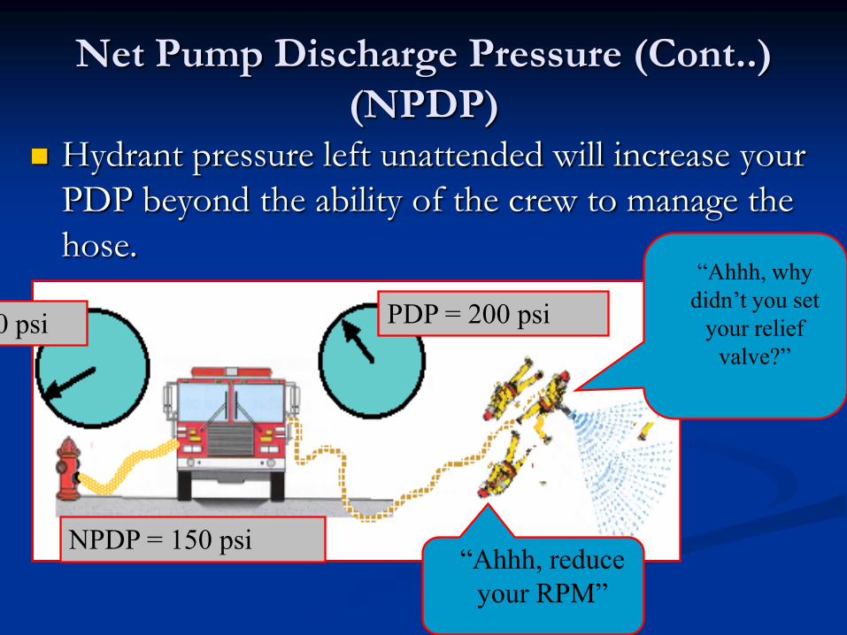
Answers 2 ½ Drill # 1
Use the Hydraulic sheet to plug in what we know.
NP = 45 PSI
ELV = 0
AppFl = 0
Figure out the GPM of 1 inch tip at 45 PSI =200
GPM
FL for 600 ft 2 ½ @ 200 GPM = 48 PSI
PDP = 93 PSI
NPDP = 43 PSI

2 ½ Handline Drill 2
400’ of 2 1/2” attack hose
Find the PDP for this semi-truck roll-over
fire. Use an 1 1/4” tip at 45 psi NP (you
make the call).
1 1/4” tip
at 45 psi NP 40 ft
Elevation gain
Photo from “Fire Service Hydraulics” E.F. Mahoney
Find the NPDP for a hydrant pressure of 75 psi.

Answers 2 ½ Drill # 2
NP = 45 PSI
ELV +/- = -20
AppFl = 0
Figure out the GPM of 1 1/4 inch tip at 45 PSI =300 GPM
FL for 400 ft 2 ½ @ 200 GPM = 72 PSI
PDP = 97 PSI
NPDP = 25 PSI
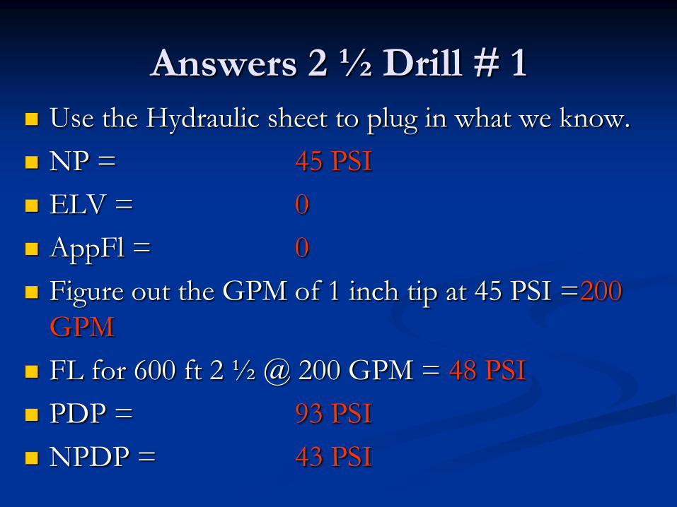
Answers 2 ½ Drill # 2 (Cont..)
What would you do in this situation?
Engage pump and gate down line.
Just flow from the hydrant?
You make the call.

Last one
Photo from “Fire Service Hydraulics” E.F. Mahoney
Hydrant pressure is 75 psi.
100’ of 3” hose
100’ of 1 3/4” hose
150 GPM
100 psi nozzles
100 psi nozzles
100’ of 1 3/4”
hose
150 GPM

Answer to the Last One
NP = 100 PSI
ELV +/- = 0
Figure out total GPM of both 1 ¾ lines flowing 150 GPM each = 300 GPM
AppFl = 0 total flow < 350 GPM
FL 1 3/4 = 35 PSI Only have to figure FL for one line because they are the same length, diameter, and
nozzle pressure IFSTA Chapt. 8 pg. 151
FL for 3 inch= 7 PSI
PDP = 142 PSI
NPDP = 67 PSI

Take A Break

Field Hydraulics
Multiple Lines 1 3/4” 200 ft liveline with a
100 psi fog nozzle @ 150 GPM
200’ of 2 1/2” with a Smoothbore & 1” Tip
A Wye Set-up with 200’ of 3” supply hose to 2 100 ft 1 ¾ lines flowing 125 gpm each with 75 psi fog nozzles.

Field Hydraulics
Multiple Lines 1 3/4” 200 ft liveline with a
55 psi TFT dual force @ 150 GPM
200’ of 2 1/2” with a Smoothbore & 1” Tip
A Wye Set-up with 200’ of 3” supply hose to 2 100 ft 1 ¾ lines flowing 125 gpm each with 100 psi fog nozzles.
Hydrant 70 PSI
Liveline Smooth Set-up
100
70
170
45
16
61
100
25
10
135
135
100

High Rise
Follow departments Sop’s for
FDC assignments

Elevation Pressure (+ or -)
IFSTA calls it “EP” we call it “Elv.”
Pressure is directly proportional to height of container (hose or pipe).
To much confusion with engine pressure EP and elevation pressure EP.

Classroom Formula:
P = .434 x Head/height
Field Formula:
1/2 psi per foot
1/2 H (Height)
High-rise
5 psi per floor
Elevation Pressure Formulas

Elv = 1/2 H (+ or -)

High-rise
5 psi per floor
MGM Fire
Las Vegas, Nev.

Elv = 1/2 H

High Rise
100’ of 1 3/4” attack hose with 100 psi fog, @ 150 gpm
100’ of 2 1/2”” hose from the class 1 standpipe
to your attack line
Two- 3” supply lines,
50’ long.
Remember: Only
count FL for the
standpipe if GPM
exceeds 350
Figure for
a 60 psi
hydrant Photo from “Fire Service Hydraulics” E.F. Mahoney
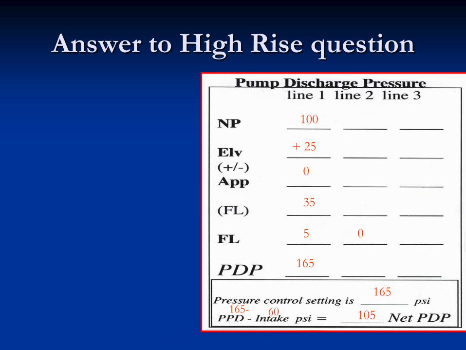
Answer to High Rise question
100
+ 25
0
35
5 0
165
165
165- 60 105

High Rise Multiple lines
100’ of 2 1/2”
With 1 1/8 tip
100’ of 2 ½ with 100 psi fog
flowing 200 gpm
Three 3” lines 100’ to the FDC.
Figure the Hydrant at 75 psi.

Answers Multiple Lines
Smooth Fog
45 100
+ 30 +20
25 25
12 8
2 2
114 137
137
137 - 75 62

High Rise
As an Operator what are you going to advise the
Firefighters on the 7th floor.
They will have to gate down the pressure.
At the Standpipe
Or at the bale (That is what I would recommend.)
Why? Possibility of more lines attached to FDC
which will take water and pressure away from you.
You don’t want to travel back to the standpipe
unless you have too.

Friction Loss (FL)
Defined on page 456
Principles of Friction Loss pages 114 to 116.
IFSTA “Pumping Apparatus
Driver/Operator Handbook”

Appliance Friction Loss (AppFL)
IFSTA: . >350 gpm, figure for AppFL
Handline evolutions:
Wye/Siamese/Gate >350 gpm = 10psi
Standpipes >350 gpm = 25psi+
Eductors are 50 psi AppFL

Finding FL in Hose
(CQ2L)
IFSTA Pumping Apparatus Driver
Handbook
pages 142 to 164.

Quick Look at the Formula
FL= CQ2L
C= coefficient for diameter of hose
Q2=
L = GPM
100
) ( 2
Length of Hose
100

Coefficients and Q2
15.5

Take a Break