Embed Size (px)
Citation preview

04-3787_ABB_OPM_PVA11 1-3kVA-RT_EN_140415 Page 1/32 ABBModifications reserved
PowerValue 11 RT 1-3 kVAUser Manual
04-3787_ABB_OPM_PVA11 1-3kVA-RT_EN_140325
© Copyright 2012 ABB, All rights reserved.

04-3787_ABB_OPM_PVA11 1-3kVA-RT_EN_140415 Page 2/32 ABBModifications reserved
This page left intentionally blank

04-3787_ABB_OPM_PVA11 1-3kVA-RT_EN_140415 Page 3/32 ABBModifications reserved
FOREWORD
The UPS system operates with mains, battery or bypass power. It contains components that carry highcurrents and voltages. The properly installed UPS system is grounded to earth and IP 20 rated againstelectrical shock and foreign objects.OPERATIONS INSIDE THE UPS MUST BE PERFORMED BY A SERVICE ENGINEER FROMTHE SUPPLIER OR FROM AN AGENT AUTHORIZED BY THE SUPPLIER.
This user manual contains guidelines to check delivery, installing and commissioning of the UPS and isintended for people who plan the installation, install, commission and use or service the UPS. Thereader is expected to know the fundamentals of electricity, wiring, electrical components and electricalschematic symbols.
THE INSTRUCTIONS IN THIS MANUAL SHOULD BE FOLLOWED DURING INSTALLATION,OPERATION AND MAINTENANCE OF THE UPS AND BATTERIES.
Read carefully all instructions and save this manual for future reference.
SYMBOLS
The following symbols are used in this manual, the list below describes each symbol.
WARNING: DANGER OF ELECTRICAL IMPACT
NOTE: READ THE INFORMATION, IN ORDER TO AVOID EQUIPMENT DAMAGES
PROTECTIVE GROUNDING TERMINAL: A terminal which must be connected to earthground prior to making any other connection to the equipmentA terminal to which or from which an alternating current or voltage (AC) may be applied orsuppliedA terminal to which or from which a direct current or voltage (DC) may be applied orsupplied
Battery
Power On, Idle or shutdown the UPS
Overload indication
Recycle
Do not dispose with ordinary trash

04-3787_ABB_OPM_PVA11 1-3kVA-RT_EN_140415 Page 4/32 ABBModifications reserved
CONTENTS
FOREWORD ........................................................................................................................ 3SYMBOLS ............................................................................................................................ 31 SAFETY INSTRUCTIONS ............................................................................................. 6
1.1 Operator precautions .................................................................................................................... 61.2 Environmental Considerations ....................................................................................................... 61.3 Declaration of Safety conformity and CE marking.......................................................................... 61.4 Inquiries ......................................................................................................................................... 71.5 Operation ...................................................................................................................................... 7
2 MAINTENANCE ............................................................................................................ 82.1 Replacing Internal Batteries ........................................................................................................... 92.2 Testing New Batteries .................................................................................................................... 92.3 Battery Recycling ........................................................................................................................... 9
3 INSTALLATION .......................................................................................................... 103.1 Delivery, Transportation, Positioning and Storage....................................................................... 10
3.1.1 Receipt of the UPS and visual inspection...................................................................103.1.2 Unpacking..................................................................................................................103.1.3 Storage of UPS ..........................................................................................................10
3.2 Site Planning and Positioning ....................................................................................................... 113.2.1 Planning before the installation ..................................................................................113.2.2 Positioning .................................................................................................................113.2.3 Rack Mount Installation ..............................................................................................113.2.4 Standalone / Tower Installation ..................................................................................13
3.3 General Characteristics ................................................................................................................ 143.3.1 Front View .................................................................................................................143.3.2 Rear View ..................................................................................................................15
3.4 Electrical Installation ................................................................................................................... 153.4.1 Commissioning ..........................................................................................................153.4.2 Connections ...............................................................................................................16
3.5 Emergency Power Off (EPO)......................................................................................................... 173.6 Installation Checklist .................................................................................................................... 17
4 OPERATION ............................................................................................................... 184.1 Control Panel ............................................................................................................................... 18
4.1.1 Selection Keys ...........................................................................................................184.1.2 LCD Display ...............................................................................................................19
4.2 Operating Mode .......................................................................................................................... 194.3 UPS Start-up and Shutdown......................................................................................................... 20
4.3.1 UPS start-up ..............................................................................................................20With mains supply ...............................................................................................................20Cold Start (UPS start-up without mains supply) ...................................................................214.3.2 UPS Shutdown ..........................................................................................................21With mains supply ...............................................................................................................21Without mains supply ..........................................................................................................21
4.4 UPS Operation ............................................................................................................................. 214.4.1 Changing the operating-mode ....................................................................................214.4.2 Navigation..................................................................................................................22

04-3787_ABB_OPM_PVA11 1-3kVA-RT_EN_140415 Page 5/32 ABBModifications reserved
5 COMMUNICATION ..................................................................................................... 275.1 RS-232 port .................................................................................................................................. 275.2 USB port....................................................................................................................................... 275.3 Dry Contact ports ......................................................................................................................... 285.4 Network Management Card (Optional) ....................................................................................... 29
5.4.1 Installing a Serial Network Management Card (optional) ............................................295.4.2 Monitoring Software ...................................................................................................29
6 TROUBLESHOOTING ................................................................................................ 306.1 Fault identification and rectification ............................................................................................ 30
7 TECHNICAL SPECIFICATION ................................................................................... 32

04-3787_ABB_OPM_PVA11 1-3kVA-RT_EN_140415 Page 6/32 ABBModifications reserved
1 SAFETY INSTRUCTIONS
1.1 Operator precautions
The user must follow the precautions and only perform the described operations. Also in thesemeasures, the operator of the UPS System must adhere to the instructions in this manual. Anydeviations from the instructions could be dangerous to the user or cause accidental load loss.
The only user operations permitted are:- Use of the LCD control panel (LCD Display) and Maintenance Bypass (if present)- Start up and shut down of the UPS (excluding the commissioning start up)- Operation of additional connectivity devices
THE SUPPLIER DOES NOT TAKE ANY RESPONSIBILITY FOR DAMAGES CAUSED THROUGHWRONG MANIPULATIONS OF THE UPS SYSTEM.
WARNING!
IT IS PROHIBITED TO REMOVE ANY SCREWS FROM THE UPSSYSTEM OR FROM THE BATTERY CABINET: DANGER OFELECTRICAL SHOCK.
WARNING!
HIGH FAULT CURRENTS (LEAKAGE CURRENTS):BEFORE CONNECTING THE MAINS YOU MUST ENSURE THATTHERE IS A PROPER EARTH CONNECTION!
WARNING!
THE USER MUST DISPLAY A WARNING SHIELD ON ALL PRIMARYUPS CIRCUIT BREAKERS. THE SERVICE PERSONNEL HAS TO BEINFORMED ABOUT DANGEROUS VOLTAGES. THE WARNINGPANELS MUST CONTAIN THE FOLLOWING TEXT: “BEFORESTARTING WITH THE MAINTENANCE WORK ON THE CIRCUITBREAKERS, MAKE SURE THE UPS IS ISOLATED.”
1.2 Environmental Considerations
To operate the UPS at the best efficiency point, your installation site should meet the environmentalparameters outlined in this manual. Excessive amount of dust or moisture in the operating environmentmay cause damage or lead to malfunction. The UPS should always be protected from the outsideweather and sunshine. The operating environment must meet the weight, airflow, size and clearancerequirements specified in the technical datasheet.
Under no circumstances, the UPS could be installed in an airtight room, in the presence of flammablegases, or in an environment exceeding environmental requirements here below.
An ambient temperature of +20°C to +25°C is recommended to achieve a long life of the UPS andbatteries. The cooling air entering the UPS must not exceed +40 °C and the humidity should be below95% (non-condensing).
1.3 Declaration of Safety conformity and CE marking
PowerValue 11 RT is designed, manufactured and commercialized in accordance with the standard ENISO 9001 of Quality Management Systems. The marking shows the conformity to the EEC Directive bymeans of the application of the following standards in accordance with the specifications of theharmonized standards:
• 2006/95/EC Low voltage directive.• 2004/108/EC Electromagnetic Compatibility directive (EMC).

04-3787_ABB_OPM_PVA11 1-3kVA-RT_EN_140415 Page 7/32 ABBModifications reserved
Standards as reference:• EN-IEC 62040-1. Uninterruptible power supply (UPS). Part 1-1: General and safety requirements for
UPS’s used in accessible areas by end users.• EN-IEC 60950-1. IT equipment. Safety. Part 1: General requirements.• EN-IEC 62040-2. Uninterruptible power supply (UPS). Part 2: EMC requirements.
The supplier’s responsibility is excluded in the event of any modification or intervention in the product bythe customer’s side.
Product Standards StandardsSafety IEC/EN 62040-1 IEC/EN 60950-1
Electromagnetic Compatibility (EMC)IEC/EN 62040-2 (C1)
IEC/EN 61000-4-2IEC/EN 61000-4-3IEC/EN 61000-4-4IEC/EN 61000-4-5IEC/EN 61000-4-6IEC/EN 61000-4-8IEC/EN 61000-2-2
Figure 1: Standards
1.4 Inquiries
Address inquiries about the UPS to the local office or agent authorized by the supplier. Please note thetype code and the serial number of the equipment and contact your nearest agent authorized by thesupplier. The serial number is shown in the nameplate of the product. For further information ontroubleshooting, go to Section 6.
1.5 Operation
Do not remove the enclosure of the UPS. This system is to be serviced by qualified service personnelonly.
Do not disconnect the mains cable from the UPS or the building wiring socket during operation as thiswould remove the ground to the UPS and of all connected loads.
An integral single emergency switching device which prevents further supply to the load by the UPS inany mode of operation should be provided in the building wiring installation.
In order to fully disconnect the UPS, press the OFF button. Wait until it is on bypass or on stand-bymode to disconnect it from the mains. Do not disconnect the equipment from the mains if it is ininverter/online-mode.
Indiscriminate operation of switches may cause output loss or damage to equipment. Refer to instructionbefore operating the UPS.
Ensure that no liquid or other foreign objects enter the UPS.

04-3787_ABB_OPM_PVA11 1-3kVA-RT_EN_140415 Page 8/32 ABBModifications reserved
2 Maintenance
PowerValue 11 (1-3 kVA) RT UPS only requires minimal maintenance. The main requirement is tocharge the UPS regularly in order to maximize the expected life of the battery. When being connected tothe mains power, whether the UPS is turned on or not, the UPS keeps charging the batteries and offersthe protective function of overcharging and over-discharging.
WARNING!
BATTERY REPLACEMENT SHOULD ONLY BE PERFORMED BYQUALIFIED PERSONNEL
EVEN AFTER THE UNIT IS DISCONNECTED FROM THE MAINS POWERSUPPLY, COMPONENTS INSIDE THE UPS ARE STILL CONNECTED TOTHE BATTERY WHICH ARE POTENTIALLY DANGEROUS.
Before carrying out any kind of service and/or maintenance, disconnect the batteries. Verify that nocurrent is present and no hazardous voltage exists in the capacitor or BUS capacitor terminals. Batteriesmust be replaced only by qualified personnel.
WARNING!
THE BATTERY CIRCUIT IS NOT ISOLATED FROM THE INPUT VOLTAGE.HAZARDOUS VOLTAGES MAY OCCUR BETWEEN THE BATTERYTERMINALS AND THE GROUND. VERIFY THAT NO VOLTAGE ISPRESENT BEFORE SERVICING.
- If the battery service life (3~5 years at 25°C ambient temperature) has been exceeded, the batteriesmust be replaced. In this case please contact your dealer.- The UPS should be charged once every 4 to 6 months if it has not been used for a long time. Thebatteries charge to 90% capacity in approximately 4 hours. However, it is recommended that thebatteries charge for 48 hours after long-term storage.
- In high temperature regions, the battery should be charged and discharged every 2 months. Thestandard charging time should be of at least 12 hours.
- Under normal conditions, the battery lifetime is 3 to 5 years. In case the battery is not in goodconditions, earlier replacement should be made.
- When the discharging time is less than 50% of specified after full charged, the battery may need to bereplaced. Please check the battery connection or contact your local dealer to order new battery.- Replace batteries with the same number and same type of batteries.
- Do not replace the batteries individually. They should be replaced at the same time following theinstructions of the battery supplier.
Batteries have high short-circuit currents and pose high risks of electric shock. Take all precautionarymeasures specified below:
- Remove all jewelry, wristwatches, rings and other metal objects- Use only tools with insulated grips and handles- Do not lay tools or metal parts on top of batteries- Wear rubber gloves and boots- Disconnect the charging source prior to connecting or disconnecting the battery terminals.
Replace fuses only by devices of the same type and of the same amperage in order to avoid firehazards.

04-3787_ABB_OPM_PVA11 1-3kVA-RT_EN_140415 Page 9/32 ABBModifications reserved
2.1 Replacing Internal Batteries
To replace the internal batteries, follow the instructions below:
1. Remove the LCD box and the screws of the front panel.2. Slide and pull the front panel to the left and remove it.3. Disconnect the cable from the UPS and the battery pack.4. Remove the right inner battery bracket.5. Pull out the battery pack and place it in a flat surface.6. Install the new battery pack.7. Screw the battery protection and reconnect the battery cable (A and B)8. Re-install the front panel back to UPS.
2.2 Testing New Batteries
Before performing a battery test, check the items below:1. The batteries should be fully charged. If this is not the case, connect the UPS to the mains power
for at least 48 hours.2. Transfer the UPS to Online or Eco Mode if not yet in one of these configurations.3. Clear out all alarms if existent4. In the Control menu, choose “Start battery test” by pressing the select button to start the battery
test either on online mode or on ECO mode (High efficiency mode).
Note that the load should be connected while doing the battery test.
2.3 Battery Recycling
WARNING!
NEVER DISPOSE BATTERIES ON FIRE AS THEY MAY EXPLODE.
DO NOT OPEN OR MUTILATE THE BATTERIES.
RELEASED ELECTROLYTE IS HARMFUL TO THE SKIN ANDEYES.
Discard appropriately the UPS, battery module and batteries and follow your local laws and regulations.
1 2 3
4 5 7

04-3787_ABB_OPM_PVA11 1-3kVA-RT_EN_140415 Page 10/32 ABBModifications reserved
3 Installation
3.1 Delivery, Transportation, Positioning and Storage
3.1.1 Receipt of the UPS and visual inspection
Upon receiving the UPS, carefully examine the packing container and the UPS for any sign of physicaldamage. In case of damage, notify immediately the carrier.
The packing container of the UPS protects it from mechanical and environmental damage. To increaseits protection, the UPS is wrapped with a plastic sheet. Preserve the packaging for later re-use.
3.1.2 Unpacking
After examining the package, open the carton box and remove the accessories.
- 1 x User manual- 4 x UPS support (feet)- 1 x IEC Cable- 1 x German Cable- 1 x USB cable- 1 x 2 pin EPO Connector- 1 x 4 pin EPO Connector- 1 x Monitoring Software CD
Rack mounting kit (optional)- 1 x ‘L’ metal slide- 1 x ‘R’ metal slide- 10 x M6 round screw- 10 x M6 clip nut- 2 x 90º metal support (“ears”)- 8 x M4 flat screws (black)- 6 x M4 round screws- 1 x User manual
Examine the UPS for any sign of damage and ensure that the received UPS corresponds to the materialindicated in the delivery note. Notify your carrier or supplier immediately if damage is apparent.
3.1.3 Storage of UPS
If you plan to store the UPS prior to use, keep the UPS in a dry, clean and cool storage room with anambient temperature between (-15 °C to +60°C) and humidity of less than 95% non-condensing. If thepacking container has been removed, protect the UPS from dust. Keep the UPS always in uprightposition and do not drop the equipment.

04-3787_ABB_OPM_PVA11 1-3kVA-RT_EN_140415 Page 11/32 ABBModifications reserved
3
3.2 Site Planning and Positioning
3.2.1 Planning before the installation
The appropriate place of installation for the unit is to be selected in such a way that the danger ofdamage to the UPS is minimized and a long service life of the device is thus ensured. Observe thefollowing instructions:
- Install the UPS in an indoor area.- Leave 25 cm of space on each side of the cabinet to enable cooling airflow and ensure that thecirculation of air to the ventilation slits is not obstructed.- Avoid excessively high temperature and excessive moisture.- Make sure that the surface is solid and flat.- Use No. 10AWG (for all models battery wire), 90°C copper wire and Anderson PP45 connectors foruser’s external battery enclosure.
3.2.2 Positioning
PowerValue 11 RT can be mounted in a rack or in a standalone configuration. Follow the instructions inthis section accordingly to the installation requirements.
Note that water condensing may occur if the UPS is unpacked in a very low temperature environment. Inthis case it is necessary to wait until the UPS is fully dried inside out before proceeding installation anduse to avoid hazards and electric shock.
3.2.3 Rack Mount Installation
PowerValue 11 RT can be installed in 19 inches racks. Both the UPS and the external battery enclosureare 2U in height.
3.2.3.1 Installing the UPS
1. Align the rack mounting ears on the side of the UPS and tighten the screws2. Assemble the rack rails with the rack-mounting kit.3. Slide the UPS into the rack rail and lock it into the structure.4. Tighten the screws and then proceed with the wiring of the UPS.
If installing additional UPS, repeat the procedures above for each cabinet.
3.2.3.2 Installing the External Battery Enclosure
1. Using the same method as for assembling the UPS, install the external battery module into therack on the top or on the bottom of the UPS.
2. Connect the earth line from UPS (port A) to Battery Module (port B)3. Remove the display box and remove the screws positioned in the front panel (in the back of the
LCD box and on the right side of the panel itself).4. Remove the front panel and connect the battery terminal (A) from the UPS to the Battery Module
terminal (B) as shown below. Remove the small cable entrance gate (C) on the side of the frontpanel to allow the outlet wire of the External Battery Enclosure to pass through the gate.
1 2

04-3787_ABB_OPM_PVA11 1-3kVA-RT_EN_140415 Page 12/32 ABBModifications reserved
5. Reassemble the front panel6. After installing the UPS into the rack, proceed with the connection of the load to UPS. Make sure
the load equipment is turned off before plugging them into the output receptacle.
3.2.3.3 Installing Multiple External Battery Enclosures
1. Remove the front panel and connect the battery terminal (A) from the UPS to the BatteryEnclosure terminal (B) shown below.
2. Connect the battery terminal (D) from the first Battery Enclosure to the battery terminal (E) fromthe second Battery Enclosure.
3. Remove the gates (C) on the side of the front panel to allow the outlet wire of the Battery Moduleto pass through the gate.
4. Reassemble the front panels.
Note: After connecting the Battery Enclosures, configure the number of battery modules in the controlpanel (refer Section 4.4). If using a nonstandard battery modules,use Anderson PP45 connectors. Setthe external battery packs 0~9 through LCD setting menu (See section 4.4.2.6). The number of batterymodules should be calculated as: n= (battery capacity Ah) /7.2.
1 2
43

04-3787_ABB_OPM_PVA11 1-3kVA-RT_EN_140415 Page 13/32 ABBModifications reserved
3.2.4 Standalone / Tower Installation
3.2.4.1 Installing the UPS
Installing the UPS in a vertical (tower) position, the UPS stands (feet)
1. Place the UPS in a vertical position (with the front panel screws to the top)2. Place the two stands (feet) towards the end of the units (see figure below).3. Place the UPS in the stands carefully.4. Pull out the LCD box. Rotate it by 90º clockwise and then push it back into the front panel.
3.2.4.2 Installing the External Battery Enclosure
1. Pull out the LCD box of the UPS and of the Battery Enclosure and rotate them by 90º clockwise.Then push the LCD box back into the front panel.
2. Place the UPS and the Battery Enclosure in a vertical position (with the front panel screws to thetop)
3. Place the two stands (feet) towards the end of the units (see figure below).4. Place the UPS and the Battery Enclosure in the stands carefully and tighten the screws on the
top of the units.5. Connect the earth line from UPS (port A) to the Battery Module (port B)6. Remove the front panel and connect the battery terminal (A) from the UPS to the Battery Module
terminal (B) as shown below. Remove the small cable entrance gate (C) on the side of the frontpanel to allow the outlet wire of the External Battery Enclosure to pass through the gate.
1 2 5 6
3
4

04-3787_ABB_OPM_PVA11 1-3kVA-RT_EN_140415 Page 14/32 ABBModifications reserved
3.2.4.3 Installing Multiple External Battery Enclosures
1. Connect the earth line between the UPS and the first Battery Enclosure. Then connect the earthline between the first Battery Enclosure and the second Battery Enclosure.
2. Remove the front panel and connect the battery terminal (A) from the UPS to the BatteryEnclosure terminal (B).
3. Connect the battery terminal (D) from the first Battery Enclosure to the battery terminal (E) fromthe second Battery Enclosure. Remove the small gates (C) on the side of the front panel to allowthe outlet wire of the Battery Enclosure to pass through the gates.
4. Reassemble the front panel.
Notes:- Up to four External Battery Enclosures can be connected to the UPS in the same way as shown
above.- After connecting the Battery enclosures, configure their quantity through the LCD display (Refer
to Section 4.4)
If using a nonstandard battery modules,use Anderson PP45 connectors. Set the external batterypacks 0~9 through LCD setting menu (See section 4.4.2.6). The number of battery modules should becalculated as: n= (battery capacity Ah) /7.2.
3.3 General Characteristics
3.3.1 Front View

04-3787_ABB_OPM_PVA11 1-3kVA-RT_EN_140415 Page 15/32 ABBModifications reserved
3.3.2 Rear View
The UPS rear panel’s description table and pictures are shown below:
Number Description1 AC output2 EPO / Dry contact input port3 USB port4 AC input5 Ground contact6 RS-2327 SNMP/ AS400 slot8 Dry contact output port
Figure 2: Rear view of PowerValue 11 RT 1 and 2 kVA
Figure 3: Rear view of PowerValue 11 RT 3 kVA
The External Battery Enclosure rear panel’s description table and picture are shown below:
Figure 4: Rear view of 36V, 48V and 72V Battery Enclosures
3.4 Electrical Installation
3.4.1 Commissioning
The UPS must be commissioned by a fully trained and authorized field service engineer before being putinto use. The commissioning of the UPS involves the connection of the UPS and batteries, theverification of the electrical installation and operating environment of the UPS, the controlled start-up andtesting of the UPS and customer training.
No. Description1 Earth port
04-3787_ABB_OPM_PVA11 1-3kVA-RT_EN_140415 Page 16/32 ABBModifications reserved
WARNING!
OPERATIONS INSIDE THE UPS MUST BE PERFORMED BY A SERVICEENGINEER FROM THE SUPPLIER OR FROM AN AGENT AUTHORIZEDBY THE SUPPLIER.
DO NOT OPERATE IN CASE OF PRESENCE OF WATER OR MOISTURE.
WHEN OPENING OR REMOVING THE UPS-COVERS YOU ARE EXPOSEDTO DANGEROUS VOLTAGES.
PHYSICAL INJURY OR DEATH MAY HAPPEN, DAMAGE TO THE UPS ORTO THE LOAD EQUIPMENT MAY OCCUR IF THESE INSTRUCTIONS AREIGNORED
3.4.2 Connections
Before installing the electrical wiring, check the nominal amperage of your incoming feeder.
WARNING!
THE CABLING CONNECTIONS MUST BE CARRIED OUT BY QUALIFIEDELECTRICAL PERSONNEL.
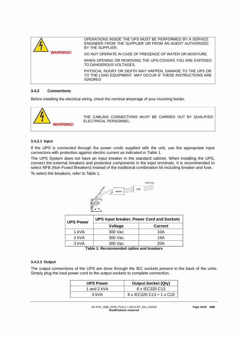
3.4.2.1 Input
If the UPS is connected through the power cords supplied with the unit, use the appropriate inputconnectors with protection against electric current as indicated in Table 1.The UPS System does not have an input breaker in the standard cabinet. When installing the UPS,connect the external breakers and protective components in the input terminals. It is recommended toselect NFB (Non-Fused Breakers) instead of the traditional combination kit including breaker and fuse.To select the breakers, refer to Table 1.
UPS PowerUPS input breaker, Power Cord and Sockets
Voltage Current1 kVA 300 Vac 10A2 kVA 300 Vac 16A3 kVA 300 Vac 20A
Table 1: Recommended cables and breakers
3.4.2.2 Output
The output connections of the UPS are done through the IEC sockets present in the back of the units.Simply plug the load power cord to the output sockets to complete connection.
UPS Power Output Socket (Qty)1 and 2 kVA 8 x IEC320 C13
3 kVA 8 x IEC320 C13 + 1 x C19

04-3787_ABB_OPM_PVA11 1-3kVA-RT_EN_140415 Page 17/32 ABBModifications reserved
Figure 5: Connection Diagram
WARNING!DO NOT CONNECT EQUIPMENT THAT COULD OVERLOAD THE UPSSYSTEM (E.G. LASER PRINTERS)
3.5 Emergency Power Off (EPO)
The EPO connector gives the user the possibility to block the output of the UPS in case of anemergency. This connector can be configured as Normally Closed (NC) of Normally Opened (NO)through the USB or RS232 port.
As a default the EPO is Normally Closed (NC) by a jumper in the rear panel. If the jumper is removed,the UPS output will not supply energy to the load until the EPO status is again modified.
Enable the EPO status Disable the EPO status
To recover to normal status, the EPO connector should first be closed. Then, enter the LCD menu (referto Section 4.4.2.4) to clear the EPO status. The UPS alarm will stop and the bypass mode will berecovered. To have the UPS in inverter mode, the selection has to be made by manual operation.
The polarity of connector could be inversed by setting in LCD menu as from section 4.4.2.6. Contactyour local supplier for further information before modifying the settings.
3.6 Installation Checklist
All packing materials and restraints have been removed from each module.Each module in the UPS system is placed in the installed location.All conduits and cables are properly routed to the UPS and auxiliary enclosures.All power cables are properly sized and terminated.A ground conductor is properly installed.Battery enclosure installation instructions have been completed.Air conditioning equipment is installed and operating properly.The area around the installed UPS system is clean and dust-free.Adequate workspace exists around the UPS and other cabinets.Adequate lighting is provided around all UPS equipment.Any optional accessories are mounted in their installed location and properly wired.Summary alarms and/or building alarms are wired appropriately. (Optional)Start-up and operational checks performed by authorized service personnel.All network connections are completed.

04-3787_ABB_OPM_PVA11 1-3kVA-RT_EN_140415 Page 18/32 ABBModifications reserved
4 OPERATION
This chapter describes how to operate the UPS through the LCD display.
WARNING!
ONLY PERSONS WHICH HAVE BEEN TRAINED BY SERVICETECHNICIANS OF THE SUPPLIER OR HIS AUTHORIZED SERVICEPARTNERS ARE ALLOWED TO OPERATE THE CONTROL PANEL OFTHE UPS.
ALL OTHER INTERVENTIONS ON THE UPS SYSTEM HAVE TO BEDONE ONLY BY SERVICE TECHNICIANS OF THE SUPPLIER.
The only user permitted operations are:
· Operate the LCD display· Start up and shut down of the UPS of the user field (excluding the commissioning start up)· Operation of additional SNMP adapters and their software
4.1 Control Panel
The user-friendly control panel is composed of two parts:· Selection Keys· Power Management LCD Display (PMD)
Figure 6: Control Panel
4.1.1 Selection Keys
TheButton
Function Illustration
Power On/Off Turn on and off the UPS or change operating mode.
Scroll up Enter/Exit the menus and scroll across the screens.
Scroll down Scroll down the menu
Select / Edit Select and confirm settings.
To see how to operate the UPS, go to Section 4.2.
LCD display
Selection Keys

04-3787_ABB_OPM_PVA11 1-3kVA-RT_EN_140415 Page 19/32 ABBModifications reserved
4.1.2 LCD Display
The LCD display gives the user a complete overview on the status of the UPS. It shows information onthe input, output, battery, load parameters, working mode and the settings on voltage, frequency andbypass presence.
It has two main backlight colors. The standard color is a blue background with white texts. In case of acritical alarm, the backlight color changes to orange with dark text. The buzzer also indicates differentUPS status. Figure 7 indicates the buzzer status meanings.
UPS condition Buzzer statusActive fault ContinuousActive Warning Beep every second
Battery UPS on battery: Beep every 4 secondsLow battery: buzzer beeps every second
Bypass Beep every 2 minutesOverload Beep twice every second
Figure 7: Definition of Alarms
When powering on, the LCD display enters the default page that shows the UPS status. From anyscreen, if the user does not press any button for more than 15 minutes, the default screen is displayed.
The status screen provides the following information:- Status summary, including operating mode and load information- Alarm status, if present (including fault and warning information)- Battery and charger status (including battery voltage, charge level and charger status)- Current runtime information
Figure 8: The default LCD display
4.2 Operating Mode
Different symbols indicate the status and the operating mode of the UPS. Such symbols appear alwaysin the position indicated in Figure 9.
Figure 9: Operating mode

04-3787_ABB_OPM_PVA11 1-3kVA-RT_EN_140415 Page 20/32 ABBModifications reserved
Status Symbol DescriptionOnline-mode UPS is running through the inverter (Online-mode)
Battery-mode UPS running on battery. (The alarm buzzer sounds every 4seconds.)
Bypass-mode
The power used by the load is supplied from the mains power viainternal filter.Note that if there is a power failure and the UPS in on bypass, itwill not transfer back to mains or to battery-mode. (This is not thecase if the UPS is in ECO-mode).In bypass-mode the alarm buzzer will sound every 2 minutes.
Stand-by-mode UPS is running but there is no power in the output.
ECO-mode
After the UPS is turned on, the power used by the load issupplied from the mains via internal filter if its power is in anacceptable range. This guarantees higher efficiency of the UPS.In case of mains failure, the UPS transfers to Online-mode orBattery-mode and the load is supplied continuously.
Note: ECO-mode can be enabled through the LCD settings orthrough the monitoring software.Warning: The transfer time of UPS output from ECO-mode tobattery-mode is 10ms and not recommended for sensitive loads.
Converter-mode
In converter-mode, the UPS runs with fixed output frequency(50Hz or 60Hz). In case of mains power failure, the UPStransfers to battery-mode and the load is supplied continuously.
Note:- Converter-mode function can be enabled through the LCDsettings or the monitoring software.- The load is de-rated to 70% in converter-mode.
WarningWarnings indicate abnormal situations that does not stop theUPS from working. In this case the UPS continues running butthe user should do corrective actions. See Section 6 for details.
Fault
In situations of failure, the UPS may disconnect the load ortransfer to bypass depending on the cause of the failure. In allcases there will be a constant alarm and the backlight of the UPSwill turn red. See Section 6 for details.
Overload
When the UPS is in overload, an alarm sounds twice everysecond. Some unnecessary loads should be disconnected oneby one to decrease the load. The load should be lower than 90%of its nominal power capacity in order to stop alarming.
Battery test UPS is performing a battery test.
Battery disconnected The battery is disconnected or defective. The UPS alarm sounds.
4.3 UPS Start-up and Shutdown
Attention: The first time the UPS is started-up, the utility must be connected. This is to prevent turningon the UPS by mistake during transportation.IMPORTANT: Switch off the connected loads before turning on the UPS. Then switch on the loads one byone after the UPS is turned on. Switch off all of the connected loads before turning off the UPS.
4.3.1 UPS start-up
With mains supply
1. Check that all cables are connected correctly and well-fixed mechanically.2. Connect the UPS to the power supply.

04-3787_ABB_OPM_PVA11 1-3kVA-RT_EN_140415 Page 21/32 ABBModifications reserved
3. Press the power-on button continuously for more than 1 second. The alarm buzzer will sound for1 second and the UPS start-up will take place.
4. After a few seconds, the UPS goes to online-mode. If the mains power is abnormal, the UPS willtransfer to battery-mode without interruption of the UPS’s output power.
Cold Start (UPS start-up without mains supply)
1. Check that all cables are connected correctly and well-fixed mechanically.2. Press the power-on button. The UPS will perform a self-test and display the status screen.3. Press the power-on button continuously for more than 1s, the alarm buzzer sounds and the UPS
start-up takes place.4. After a few seconds, the UPS transfers to battery-mode. When the UPS is again supplied with
power from the mains, the UPS transfers to online-mode without interruption in the output of theUPS.
4.3.2 UPS Shutdown
With mains supply
1. If the UPS is working on bypass-mode, go to step 3.2. If the UPS is on online-mode, press the power-on button continuously for more than 3s. The
alarm buzzer will sound and the UPS will transfer to bypass-mode. Note: the output is stillenergized.
3. Disconnect the mains power supply and a few seconds later the display will shut down and theoutput voltage will be removed from the UPS output terminal.
In case the bypass has been disabled through the Settings menu, press the power-on button for morethan 3s to shutdown the UPS. The unit will change from online to stand-by-mode. Then, simplydisconnect the input power cable and a few seconds later the display will shutdown.
Without mains supply
1. To power off the UPS, press the power on/off button continuously for more than 3s. The alarmbuzzer will sound for 3s and the output power will be immediately cut-off.
2. After a few seconds, the display will shut down and the output voltage will be removed from theUPS output terminal.
4.4 UPS Operation
Information regarding the status of the UPS, measurements, events and general information on the UPSare available through the LCD display. This chapter describes how to navigate through the display andhow to adjust the user’s settings.
4.4.1 Changing the operating-mode
To change the operating-mode, the power-on button is used as follows:- From online-mode to bypass-mode: Press the power-on button for 3s.- From bypass-mode to online-mode: Press the power-on button for 3s.- From bypass-mode to battery: Disconnect the power supply cable- From battery-mode to online-mode: Connect the power supply to the UPS and it will transfer
automatically to online-mode.
Note: If the bypass is disabled in the settings menu, when pressing the power-on button for 3s, the UPSgoes from online-mode to stand-by-mode.

04-3787_ABB_OPM_PVA11 1-3kVA-RT_EN_140415 Page 22/32 ABBModifications reserved
4.4.2 Navigation
To navigate through the UPS screens, the scroll buttons are used.From the main screen (UPS status screen), press or for information on alarm and battery.From the main screen, press for more than 1s to enter the main menu. The main menu includes thefollowing submenus: UPS status, event log, measurements, control, identification, settings.Figure 10 shows details on how to navigate through the menus and submenus.
Figure 10: Main menu tree
4.4.2.1 UPS Status
Contains general information on the status of the UPS.
4.4.2.2 Event log
To enter this menu, press . In this menu the last 50 events, alarms and faults occurred in the UPS aredisplayed. The alarms are indicated by the corresponding, event code and operating time of UPS whenthe event occurred. To navigate through the events and alarms, press or .
4.4.2.3 Measurements
To enter this menu, press . The following measurements are displayed:MeasurementsOutput power [W]Output power [VA]Output current [A]Load percentage [%]Output voltage [V]Output Freq. [Hz]Input voltage [V]Input Frequency [Hz]Battery Voltage [V]Battery Capacity [%]DC Bus Voltage [V]Temperature [oC]
To navigate through the measurements, press or .

04-3787_ABB_OPM_PVA11 1-3kVA-RT_EN_140415 Page 23/32 ABBModifications reserved
4.4.2.4 Control
From this menu, the user can control some features of the UPS. The possible operations are indicatedbelow:
Control Possible Values Default ValuesBuzzer muteStart battery testLoad segmentsClear EPO statusReset fault stateClear event logRestore factory settings
No/YesSchedule No/YesSeg1 and seg 2: on/offNo/YesNo/YesNo/YesNo/Yes
NoNoOn / OnNoNoNoNo
To modify the parameters, press . Then scroll up or down to modify the parameters. To confirm theselection, press for more than 1s.
Error! Reference source not found. gives an overview on how to navigate on the control menu.
Figure 11: Control menu tree
Examples:
- Clear EPO status: Once the EPO status is enabled, the UPS output is cut-off. To recover the normalstatus, EPO connector must first be closed. Enter this menu to clear the status of EPO. The UPS willstop alarming and will recover in Bypass-mode. Note that the UPS needs be turned on by manualoperation.
Note: First make sure the EPO signal is inactive or the LCD will show that the EPO active status couldn’tbe cleared.

04-3787_ABB_OPM_PVA11 1-3kVA-RT_EN_140415 Page 24/32 ABBModifications reserved
Figure 12: Clear EPO status
- Reset fault status: When a failure occurs, the UPS goes to fault-mode and the buzzer alarm sounds.After checking the reason of the failure and taking the appropriate corrective actions, enter this menu toreset the error status and recover the normal status. The UPS alarm will stop and will go to bypass-mode.
- Restore factory settings: All the factory settings are recovered. Note that this operation can only beexecuted when the UPS is in bypass-mode.
4.4.2.5 Identification
Press on the Identification menu to navigate through its data. The identification information includesUPS serial number, firmware serial number and model type. Press for more than 1s to return to thelast main menu.
Figure 13: Identification menu tree
4.4.2.6 User’s Settings
Some settings can impact on the performance of the UPS and others can enable and disable functionswithin the UPS. Failures and reduced protection can occur if the equipment is not set in an adequateway. Note that most settings should be done only with the UPS in bypass-mode.
Press in the Settings menu to enter the sub-menus.To modify a parameter, press and scroll up or down. To confirm the selection press this same button
for more than 1 second.

04-3787_ABB_OPM_PVA11 1-3kVA-RT_EN_140415 Page 25/32 ABBModifications reserved
Figure 14: Setting menu tree
If the User password is enabled, the user must enter the password 4314 by pressing the buttons ,and . It is used mainly to protect against modifications in the Settings menu.The possible operations are indicated in Table 2: Settings menu information
Submenu item Optional Values Default valueLanguage English / Chinese EnglishUser password enabled/disabled disabledAudio alarm enabled/disabled enabledRated output voltage 208/220/230/240V 230VOutput frequency autosensing/50/60Hz autosensing
Power strategy** normal/high efficiency (ECO-mode)/ converter normal
DC start (Cold start) enabled/disabled enabledSite wiring fault alarm enabled/disabled disabledAmbient temperature warning enabled/disabled enabledAutomatic battery tests period 0-31 days 7 daysAuto Restart enabled/disabled enabledAutomatic overload restart enabled/disabled enabledAuto Bypass enabled/disabled disabledShort circuit clearance enabled/disabled disabledBypass voltage low limit 120~215V 184VBypass voltage high limit 245~276V 264VBypass frequency low limit 40~49.5 Hz 45 HzBypass frequency high limit 50.5~70 Hz 55 HzEco-mode voltage low limit 5%~10% 5%

04-3787_ABB_OPM_PVA11 1-3kVA-RT_EN_140415 Page 26/32 ABBModifications reserved
Eco-mode voltage high limit 5%~10% 5%Submenu item Optional Values Default valueEco-mode frequency low limit 5%~10% 5%Eco-mode frequency high limit 5%~10% 5%External Battery modules*** 0 - 9 0
Set running time Day:hour:minute:second0000:0000:00~9999:23:59:59 Running time
LCD contrast -5~+5 0Table 2: Settings menu information
**Read Section 4.2, before using high efficiency (ECO-mode) or converter function.***Ensure the real battery quantity is same as the settings not to damage the batteries.
Example: Setting the rated output voltage value (Figure 15) and setting running time (Error! Referencesource not found.)
Figure 15: Setting rated output voltage value

04-3787_ABB_OPM_PVA11 1-3kVA-RT_EN_140415 Page 27/32 ABBModifications reserved
5 COMMUNICATION
A USB and an RS-232 port are available to enable the communication between the UPS and a remotecomputer/station. Only one communication port can be active at a time and the priority is given to theUSB port.Once the communication cable is installed, the power management software can exchange informationwith the UPS. The software collects information from the UPS and indicates the status of the device, thepower quality of the mains and the battery autonomy of the units.In case of a power failure and a predicted shutdown of the UPS due to low battery autonomies, themonitoring system is capable of saving the data in the load and of initiating the shutdown of theequipment connected to the UPS.
5.1 RS-232 port
An RS-232 port is available for UPS monitoring, control and firmware updates. To establishcommunication between the UPS and a computer, connect one end of the serial communication cablethat comes with the UPS to the RS-232 port on the UPS and the other end of the serial cable to the RS-232 port on a computer.
The cable pins for the RS-232 communication port are described in Figure 16 and in Table 3.
Figure 16: RS-232 Communication Port (DB-9 Connector)
PinNumber
SignalName
Function Direction fromthe UPS
1 Unused Not applicable2 Tx Transmit to external device Out3 Rx Receive from external device In4 Unused Not applicable5 GND Signal common
(tied to chassis) Not applicable
6 Unused Not applicable7 Unused Not applicable8 Unused Not applicable9 Unused Not applicable
Table 3: RS- 232 Port Pin Assignment
5.2 USB port
The UPS can communicate with an USB-compliant computers. To establish communication between theUPS and a computer, connect the USB cable that comes with the UPS to the USB port on the UPS.Connect the other end of the USB cable to the USB port on a computer.

04-3787_ABB_OPM_PVA11 1-3kVA-RT_EN_140415 Page 28/32 ABBModifications reserved
5.3 Dry Contact ports
Remote alarm indication is possible through the potential free (dry contact) ports positioned in the rear ofthe UPS. The 4-pole connector correspond to the input contacts. The signal input to control UPSOn/Off/Maintain bypass statuses needs to be configured through the LCD setting menu or protocol command. Thedefault input contact is “Disabled”.
Figure 17: Input Dry contact schematic
Dry contact input signal DescriptionDisable Disable the function.UPS On One second pulse activate.
If active, the UPS turns on if the UPS is not on inverter.UPS Off One second pulse activate.
If active, the UPS turns off if the UPS is on inverter.Maintain bypass One second pulse activate.
If active, the UPS will transfer to bypass-mode. Torecover to normal status, inactivate the signal and turnon the UPS by manual operation.
The 2-pole connector correspond to the output contacts. The relay output can be configured through theLCD setting menu or protocol command, the default output contact corresponds to “Summary Alarm”.The possible alarms are described in the table that follows.
Figure 18: Output Dry Contact schematic
Dry contact output signal DescriptionSummary Alarm Activated when any warning happensOn Battery Activated when the UPS operates on batteryBattery Low Activated if battery autonomy is lowUPS ok Activated when the UPS has no alarms and no fault.On Bypass Activated when the UPS has bypass output.
Note: The relay output contact must not be connected to any utility connected circuits. Reinforcedinsulation to the utility is required. The relay output contact has a maximum rating of 30Vac/1A and60Vdc/2A normal values.

04-3787_ABB_OPM_PVA11 1-3kVA-RT_EN_140415 Page 29/32 ABBModifications reserved
5.4 Network Management Card (Optional)
PowerValue 11 is equipped with an intelligent slot for optional cards for remote management of the UPSthrough internet / intranet. Either of the accessories below can be installed in the intelligent slot.
SNMP Card - SNMP, HTTP and monitoring capabilities through a Web browser interface.AS400 Card - AS400 card for AS400 communication protocol.
5.4.1 Installing a Serial Network Management Card (optional)
Each UPS has a communication slot for an optional Serial Network Management (SNMP) Card. Afterinstalling an SNMP card, an environmental monitoring probe can be connected to the UPS.
Note: The UPS does not have to be shutdown before installing a communication card.
To install the Network Management Card, go through the following steps:1. Remove the two screws that protect the communication slot of the UPS.2. Insert the SNMP card into the communication slot.3. Screw the SNMP card onto the slot using the screws removed in step 1.
For more information on the SNMP Cards, see the SNMP User's Manual.
5.4.2 Monitoring Software
ABB UPS can be monitored through a software that allows the user to monitor the UPS. The softwareprovides a remote and safe shutdown for multi-client systems in case of absence of power in the outputof the UPS. Instructions on how to install the software are provided with the network management cards.

04-3787_ABB_OPM_PVA11 1-3kVA-RT_EN_140415 Page 30/32 ABBModifications reserved
6 TROUBLESHOOTING
6.1 Fault identification and rectification
Alarm and events identify warning situations and notify errors or potential failures of the system. Theoutput of the UPS is not necessarily affected in case of an alarm but taking the correct actions mayprevent loss of power to the load. If the UPS system does not operate correctly, attempt to solve theproblem using the table below.
Problem Possible cause RemedyNo indication, no warning toneeven though system is connectedto mains power supply
No input voltage Check building wiring socket outlet and input cable.
Emergency supply period shorterthan nominal value
Batteries not fully charged /batteries with defect
Charge the batteries for at least5 - 8 hours and then check capacity. If the problemstill persists, consult your supplier.
Fan failAlarm Code: 84
Fan abnormal Check if the fan is running
Battery over voltageAlarm Code:16
Battery is over charged Stop charging to battery automatically, and afterthe battery voltage is normal and the mains isnormal, charge automatically again.
Battery lowAlarm Code:12
Battery voltage is low If audible alarm sounds every second, the batteryis almost empty.
Charge failAlarm Code:15
The charge is broken Notify dealer.
Inverter temperature highAlarm Code:86
Inside temperature of theUPS is too high
Check the ventilation of the UPS, check theambient temperature.
Ambient temperature highAlarm Code:82
The ambient temperature istoo high
Check the environment ventilation.
Battery openAlarm Code:11
Battery pack is notconnected correctly
Check if the battery bank is connected to the UPS.Check if the battery breaker is turned on.
Service BatteryAlarm Code:13
Battery may need to bereplaced
Consult dealer
OverloadAlarm Code: 41/42/43
Overload Check the loads and remove some non-criticalloads.Check whether some loads have failures.
Site failAlarm Code:04
Phase and neutralconductor at input of UPSsystem are reversed
Rotate mains power socket by 180° or connectUPS system.
EPO activeAlarm Code:71
EPO function is enabled Turn off the EPO switch.
Bus fault (Low / high / Unbalance /Soft start)Alarm Code:22/21/23/25
UPS internal fault Consult your supplier
Inverter fault(Low/high/soft start)Alarm Code:33/32/34
UPS internal fault Consult your supplier
Over temperature faultAlarm Code:81
Over temperature Check the ventilation of the UPS, check theambient temperature and ventilation.
NTC openAlarm Code:87
UPS internal fault Consult your supplier
Inverter shortAlarm Code:31
Output short circuit Remove all the loads. Turn off the UPS. Checkwhether the output of UPS and loads is shortcircuited. Make sure the short circuit is removed,and the UPS has no internal faults before turningon again.
Bus shortAlarm Code:24
UPS internal fault Consult your supplier

04-3787_ABB_OPM_PVA11 1-3kVA-RT_EN_140415 Page 31/32 ABBModifications reserved
Please have the following information before calling the After-Sales Service Department:
1. Model number, serial number2. Date on which the problem occurred3. LCD/LED display information, Buzzer alarm status4. Mains power condition, load type and capacity, environment temperature, ventilation condition5. Information on external battery pack (battery capacity, quantity)

04-3787_ABB_OPM_PVA11 1-3kVA-RT_EN_140415 Page 32/32 ABBModifications reserved
7 TECHNICAL SPECIFICATION
GENERAL DATA 1000 VA 2000 VA 3000 VAOutput rated power [W] 900 W 1800 W 2700 WOutput power factor 0.9Topology True online double conversionInbuilt batteries yesINPUTNominal input voltage 208 / 220 / 230 / 240 VAC
Input voltage tolerance 110-276 VAC (depends on load level)Input current THD <5% with full resistive loadFrequency range 45-55 Hz / 54-66 HzPower factor ≥0.99OUTPUTRated output voltage 208 / 220 / 230 / 240 VAC
Voltage tolerance(referred to 230V) ±1%
Voltage distortion ≤2% linear load, ≤5% non-linear loadOverload capability 12s.: 102%-130% load / 1.5s.: 130%-150% load / 100ms.: >150% load (Inverter)Nominal frequency 50 or 60 Hz ± 0.2 HzCrest Factor 3:1TRANFER TIMEBatteryßà inverter 0 msBypassßàinverter 0 msInverter to Eco-mode 1 msEco-mode to inverter <10 msEFFICIENCYAC-AC > 88% > 89% > 92%In eco-mode > 95%ENVIRONMENTProtection rating IP 20Storage temperature -15 – +60°COperating temperature 0 – 40°CRelative humidity 0-95% (Non-condensing)Altitude (above sea level) 1000m without de-ratingBATTERIESType VRLA, vented lead-acidNumber of batteries 3 4 6Battery capacity 7.2 Ah 9 Ah 9 AhBackup time > 5 minutes >3 minutes >3 minutesCharging current 1.5 ARecharge time 3 hours to 90%COMMUNICATIONSUser interface LCD displayCommunication cards SNMP (option), AS400 relay card (option)STANDARDSSafety IEC/EN 62040-1EMC IEC/EN 62040-2Performance IEC/EN 62040-3Manufacturing ISO 9001:2008, ISO 14001:2004WEIGHT, DIMENSIONSWeight 16.2 19.7 28.6Dimensions WxHxD 438x86.5x550mm 438x86.5x608*Technical specifications are subject to change without notice.