Embed Size (px)
Citation preview
PowerIT RESIBLOC® Dry Type Distribution Transformer 250 kVA to 40,000 kVA
through 45 kV
Operation & Maintenance Manual for Indoor and Outdoor Installation

Operation and Maintenance Manual RESIBLOC® Transformers
- 1 -
Index 1 Safety Advice 2 Transportation & Delivery 2.1 Product Identification 2.1.1 Product Description 2.2.1 Transport by Forklift Truck or
Lift-truck 2.2.2 Transportation by Crane 2.3 Storage 3 Commissioning 3.1 Site Conditions 3.2 Assembly; Mounting &
Attachment 3.3 Distances 3.4 Working Conditions 4 Use 4.1 Certification by CE 5 Servicing, Inspection & Cleaning 6 Recycling 7 Fire Extinguishing 8 Protection Equipment 8.1 Temperature Monitoring 8.2 Dial Type Thermometer 8.3 PTC Sensors, Pt100, etc. 9 Cooling Fans
Read and carefully study this Operation & Maintenance Manual before Installation & Commissioning!
For any user installation and service questions please contact
ABB Transformatoren GmbH for support!

Operation and Maintenance Manual RESIBLOC® Transformers
- 2 -
1 Safety Advice - before Installation & Service
- Please read this manual before transportation, installation and commissioning of your RESIBLOC®
Transformer carefully. - Ensure the correct worktools and necessary appliances are ready and available for use. - Terminals are designed only for electrical loading, connected to flexible cables. - The supplied transformer design complies to the purchasing specification details. For this reason, only loading conditions as detailed on the rating plate must be used. Should these loading conditions be changed or modified at any time, it is strongly recommended to advise this to ABB Transformatoren GmbH. - Connections other than those detailed on the transformer’s rating plate must not be made. - Never use units without earthing connections and ensure that they comply to respective National Standards and Requirements. - Never reconnect under load! - Never remove enclosures or enclo-sure panels whilst energised! - Never operate without alarm or monitoring systems connected.
- Every transformer generates a magnetic field, that is only fractionally reduced through the use of a transformer protection enclosure. For this reason, nobody using a Heart-Pace-maker or other metal-implantation inserted within their body can ever be allowed within 3 m of an energised transformer in operation. - The products described here are all tested to IEC and DIN/VDE standards to achieve the maximum quality and longest service life-time. - It is impossible to cover all product variations within this manual. Therefore, certain designs and/or optional accessories must be individually detailed, where applicable.
Operation and Maintenance Manual RESIBLOC® Transformers
- 3 -
2 Transportation & Delivery - A detailed inspection must be made on the received transformer, before and after offloading, with special attention to all accessories and extra parts. - Comments to any visible damage must be entered onto the Delivery Note, and forwarded immediately to ABB Transformatoren GmbH and the forwarder together with a detailed Damage Report. - Never accept receipt of a noticeably damaged transformer without contac-ting the factory supplying the unit. - In order to perform the inspection, all supplied documents must be available (Shipping Documents, Packing Lists, Dimensional Drawings, this Manual etc.). The following Check List shows the inspection criteria that must be checked and where a transport damage could be found:
�� Visible damage to any tie-down straps or packing (if present)?
�� Are any of the transformers fasteners or anchor-points damaged?
�� Does any evidence indicate the transformer has been re-loaded or that it has moved or slipped during transport? (original transporter has changed after loading at the factory)
�� Is any external damage visible?
�� Are any of the lifting eyes or any of the cast resin coil supports bent, broken or otherwise damaged?
�� Is any coil damage evident?
Accessories/Extras
�� Have all the parts shown in the Packing List been received?
�� Is there any packing damage?
�� Is there any dampness/humidity evident on the packing?
�� Are all loose parts in perfect condition?
Please immediately report all missing parts to the transporter/ forwarder. In the event the delivered goods do not correspond to the Packing List, please report this immediately to ABB Transformatoren GmbH, indicating the relevant serial number.
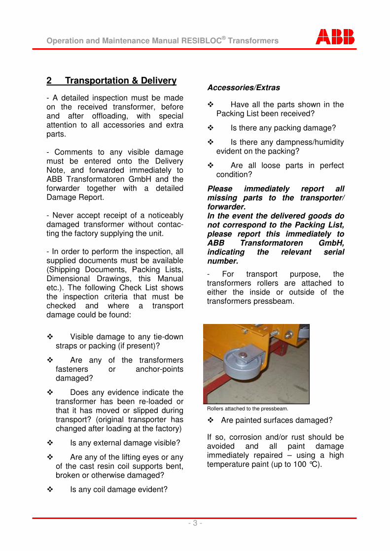
- For transport purpose, the transformers rollers are attached to either the inside or outside of the transformers pressbeam.
Rollers attached to the pressbeam.
��Are painted surfaces damaged?
If so, corrosion and/or rust should be avoided and all paint damage immediately repaired – using a high temperature paint (up to 100 °C).
Operation and Maintenance Manual RESIBLOC® Transformers
- 4 -
Transportation
- Always check before every move-ment which transportation method is the best suitable. Changes should be avoided to minimize damage.
- Before any movement or transpor-tation, the following should be checked: �� Only move the transformer in
the upright position.
�� Never allow chains, slings or other means used to hold the transformer fast to cause any damage. Special attention must be taken with the HV & LV terminals, cooling fans etc.
�� Strong vibrations, swinging and sudden movements during transport can easily result in serious damage.
�� Always observe all regulations in respect of working with transport vehicles. The transformers weight is detailed in the units Delivery Note, or Rating Plate.
�� Secure the transformer against any movement during transportation, and ensure all relevant laws regarding the tranportation of heavy goods on public roads are fully met.
2.1 Product Identification - This manual details a 3 phase RESIBLOC� cast-resin dry-type trans-former, built by ABB Transformatoren GmbH, Brilon. - The transformer rating and main electrical data, identical to the transformer rating plate, are shown again in the enclosed document. - Please carefully check that this matches the details on the transformer mounted rating plate. In the event of any discrepancy, please report this immediately ABB Transformatoren GmbH, Brilon.
- Always provide at least the following details, whenever contacting ABB Transformatoren GmbH, or should service become necessary:
- Type - Serial Number - Year of Manufacture - Nominal Rating - Nominal Voltage - Nominal Frequency - The results of all routine testing, and eventually any additional type or special testing can be seen in the attached test reports.
Operation and Maintenance Manual RESIBLOC® Transformers
- 5 -
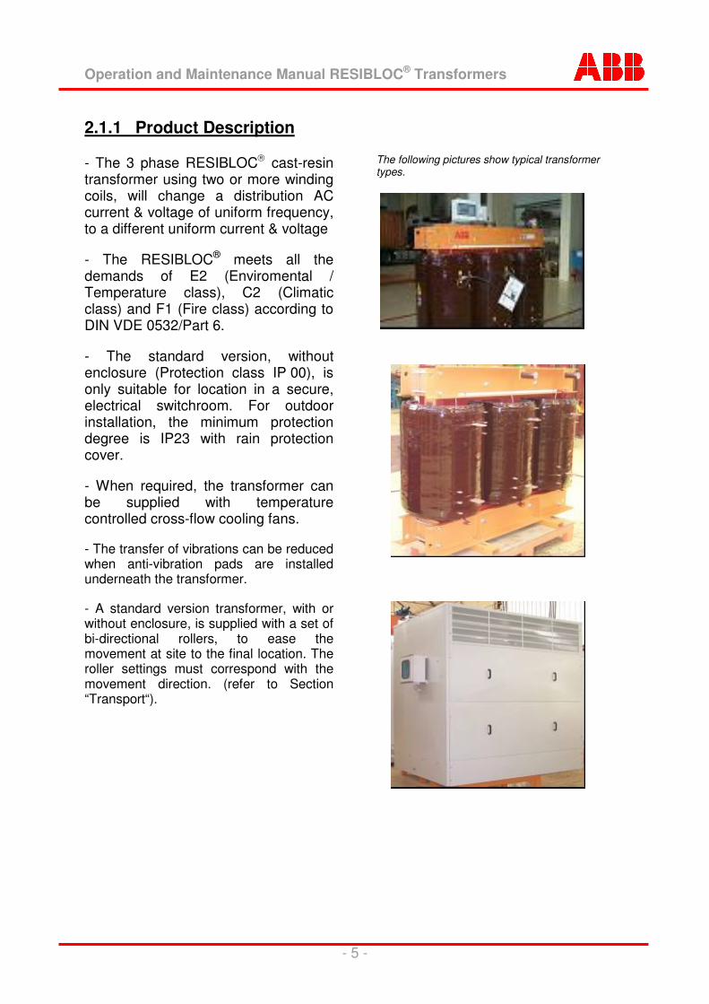
2.1.1 Product Description - The 3 phase RESIBLOC� cast-resin transformer using two or more winding coils, will change a distribution AC current & voltage of uniform frequency, to a different uniform current & voltage
- The RESIBLOC® meets all the demands of E2 (Enviromental / Temperature class), C2 (Climatic class) and F1 (Fire class) according to DIN VDE 0532/Part 6.
- The standard version, without enclosure (Protection class IP 00), is only suitable for location in a secure, electrical switchroom. For outdoor installation, the minimum protection degree is IP23 with rain protection cover.
- When required, the transformer can be supplied with temperature controlled cross-flow cooling fans.
- The transfer of vibrations can be reduced when anti-vibration pads are installed underneath the transformer.
- A standard version transformer, with or without enclosure, is supplied with a set of bi-directional rollers, to ease the movement at site to the final location. The roller settings must correspond with the movement direction. (refer to Section “Transport“).
The following pictures show typical transformer types.
Operation and Maintenance Manual RESIBLOC® Transformers
- 6 -
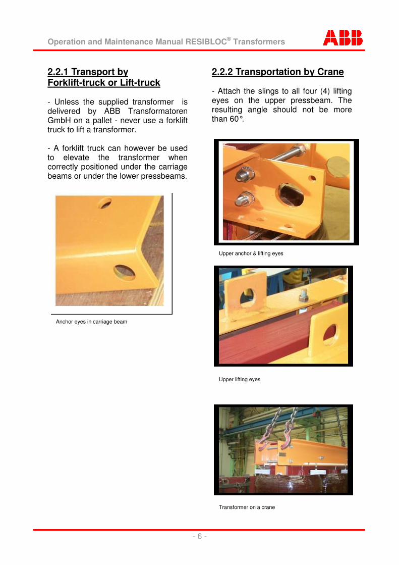
2.2.1 Transport by Forklift-truck or Lift-truck - Unless the supplied transformer is delivered by ABB Transformatoren GmbH on a pallet - never use a forklift truck to lift a transformer. - A forklift truck can however be used to elevate the transformer when correctly positioned under the carriage beams or under the lower pressbeams.
2.2.2 Transportation by Crane - Attach the slings to all four (4) lifting eyes on the upper pressbeam. The resulting angle should not be more than 60°.
Anchor eyes in carriage beam
Upper anchor & lifting eyes
Upper lifting eyes
Transformer on a crane
Operation and Maintenance Manual RESIBLOC® Transformers
- 7 -
2.3 Storage - The correct conditions must be available, if the transformer should need to be stored either before commissioning, or at any later date. These conditions are detailed in the document already in hand, “Preparation and Conditions at Site“.
- Always use a protection foil to cover the transformer against dust and dirt (especially at site!).
- Whenever the transformer is to be stored for any lengthy period, silicagel must be placed inside the packing to minimise humidity. This material must be regularly checked to ensure a low humidity is maintained, and the silicagel should be immediately replaced upon colour change.
3 Commissioning Commissioning Checks:
�� Check all HV terminal connections are tightened & secure, and free of all dust and dirt.
�� Check the earthing terminal connections are tightened and that earth has been established.
�� Check the necessary clearances:
a) between live voltage parts.
b) between live voltage and earthened parts.
c) between all cables and the HV coil windings.
d) between all cables and HV reconnections & tapping connections.
�� Check all sensors - open the sensor current-circuit, with a very high resistance in the current-circuit the connected relay will operate. All connections must be tightened.
�� Check the installation of all control circuits. Pay particlular attention to damaged insulation and loose connections.
�� Check for any discrepancies with the transformers connections and those shown in the documents of the order acknowlegement, and also shown in the rating plate mounted on the transformer.
�� Check if all spacers are tight.
�� Check if the available cooling is sufficient.
�� For transformers with cooling fans - Check if the fans are connected to a power supply and functions fault-free.
�� Check that all tools and materials used during commissioning have been removed from the transformer.
�� Whenever individual cable testing is to be made, the cables must first be seperated from the transformer.
�� Touch-up any paint damage.
�� Check that the transformer is clean and free of all foreign matter. Check especially for small parts in the cooling channels and on the upper yoke. If necessary, clean the transformer using a vacuum cleaner and/or compressed air.
Operation and Maintenance Manual RESIBLOC® Transformers
- 8 -
When used in a parallel connection pay special attention to: Check that all conditions necessary for use in a parallel connection are fulfilled. If necessary, these conditions can be received from ABB Transformtoren GmbH. 3.1 Site Conditions The transformer should be set up at the intended site and the connections installed as detailed under "Section 3.2". Should the transformer have become dirty in any way, it must be cleaned before start-up. If any work must carried out close to the transformer before commissioning, the transformer must be protected by a tarpaulin from all contamination. Any dust, scrap metal, screws, nuts & bolts, pins and similar such small articles which come into the windings, will lead to serious damage of the transformer. Secure the transformer against any mechanical damage (i.e. through ladders, scaffoldings or similar). 3.2 Assembly; Mounting and Attachment Electrical connections
When mounting the transformer, strictly maintain the order of activities indicated here. Before connections are finally created, it must be guaranteed that:
All intended lines and the earthing system are prepared according to the requirements (see section "3"), the transformer electrical data (see rating
and diagram plate) conforms with the electrical data of HV and LV system networks.
Safety distances between live parts, and also live and grounded parts are not below the minimum requirements. In particular, the distances between cables and the high-voltage coil windings.
All connections must be safely and firmly mechanically attached. We recommend all bolts used on electrical connections are tightened with a torque wrench. This way, all connections are evenly tightened, and over- tightening is avoided.
Please refer to the following table for recommended torques values: Bolt size M8 M10 M12 M16 M20 M24
Suitable torque [Nm] 15 30 60 120 240 480
Re-tighten the bolts after some weeks, with the transformer switched off, to the same torque values. Tapping changes
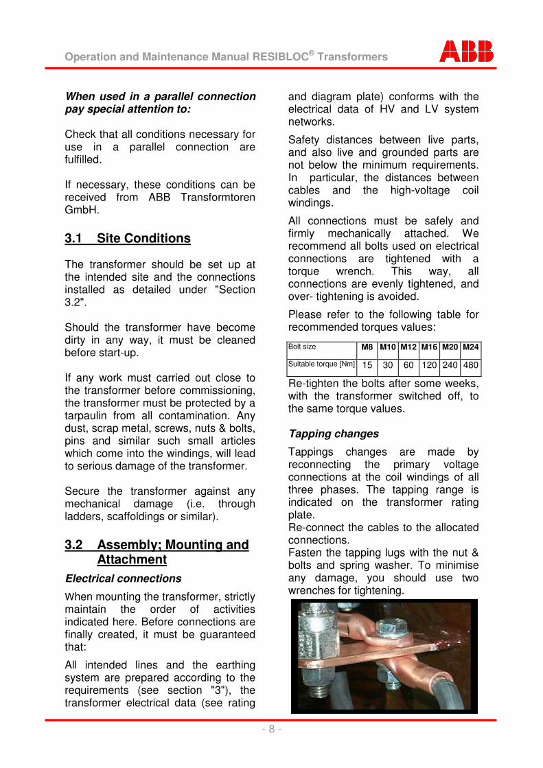
Tappings changes are made by reconnecting the primary voltage connections at the coil windings of all three phases. The tapping range is indicated on the transformer rating plate. Re-connect the cables to the allocated connections. Fasten the tapping lugs with the nut & bolts and spring washer. To minimise any damage, you should use two wrenches for tightening.
Operation and Maintenance Manual RESIBLOC® Transformers
- 9 -
Create connections
Transformers with a secondary neutral connection: The primary voltage must not be attached before a connection has been laid, connecting the secondary side neutral conductor and the neutral conductor of the main power network. This will avoid any unnecessary capacitive connection transfer, from a high potential on the secondary winding, should a ground fault on the main power network occur.
Perform all connections in accordance with VDE 0101, and/or your national standard. Adhere strictly to the given instructions!
Ground the transformer (earthing-screw on the undercarriage beam).
For re-connectable transformers: Check the voltage ratio (see transformer rating plate). If necessary, you must select the necessary ratio. Check insulation resistances: Electrically separate coil windings - against each other and each coil against earth. Use for this check an isolation test device.
Minimum resistances must amount to at least 1000 ohms/V of operating voltage. Should a dry type transformer become damp through unusual circumstances, the normal insulation resistance will be reduced. The transformer must then be dried. Suitable drying methods can be received from your nearest ABB-office.
Check the voltage and phase displacement of the existing electrical network.
Clean all connections and connector lugs and polish these bright. When connecting aluminum with copper parts: use Cupal plates inbetween.Use corrosion protection on all bright connections (vaseline, contact fat or
sim.). With aluminum connections also use corrosion protection between the aluminum and Cupal plates.
Connect the temperature monitoring, and check the system and functions.
Connect the terminals. Ensure that no severe bending or other mechanical stresses have developped in the cables, and that they are not cross-connected. Flexible connections should always be used with loads of 1000 Amps and above, between the transformers connecting terminals and busbars.
Use cable strain relief, to ensure the necessary contact pressure is main-tained. This requirement is fulfilled, if cable tightening is according to DIN 6796.
Create the electrical connections. The connection order of the primary voltage can be taken from the transformer rating plate.
Use corrosion protection on all bolted connections.
For transformers with enclosures: close any cable entries not in use. Secure the transformer against movement at site. 3.3 Distances For transformers without enclosures, minimum air safety distances must be maintained according to the relevant standards (DIN, IEC or VDE). These standard values can be found in the document "preparation at site". Please note that concrete walls are often steel-reinforced, therefore the minimum safety distances should always be kept.
Operation and Maintenance Manual RESIBLOC® Transformers
- 10 -
Transformers with enclosures must keep the distance from the enclosure base to the roller and/or foot lower edge (floor). Should the rollers/feet be removed at site, the distance to the floor must not be reduced. The only exception would be a specially ventilated transformer. Sufficient wall distances must be kept at the height of the exit openings. As a rule, 2/3 of ventilation screen height are to be kept as distance. (example IP23: ventilation screen height 540mm → wall distance 360mm)
3.4 Working conditions In order to ensure a long service life and a troublefree operation, environ-mental conditions may require regular cleaning. A maintenance schedule should be established, according to the intensity and nature of the contami-nation, in order to provide the least problems. Any maintenance work must only be performed with the transformer disconnected and de-energising of the network. Remove dust layers using a vacuum cleaner. Any greasy deposits on the coils or insulation surfaces will require special cleaners. All safety recommendations of the cleaning material manufacturer must be considered (fresh ventilation, etc.). After cleaning, the transformer must be completely dried before re-energising. All other surfaces, as isolators and other electrical components should be dusted down with a dry cloth.
By adhering to the following conditions, cleaning with compressed air or nitrogen is also possible:
�� max. pressure should never exceed 3 bar
�� the gas must be clean and dry
�� a vacuum is used to capture any developing dusts.
Should the maintenance intervals become too frequent in your opinion alternative measures should be considered. Better transformer ventilation, using clean or filtered air may be an answer. Contact ABB Transformatoren GmbH to discuss the possible arrangements with improved transformer ventilation or improvement of the enclosure protection degree, as these could be possible.
Operation and Maintenance Manual RESIBLOC® Transformers
- 11 -
4 Use Operating temperature
As insulation class F is used by the transformer, a temperature control device must be used that guarantees it will be switched off when the hot spot temperature of 155 °C is reached. Information details of the control device will be found under optional accessories, if in the scope of supply. Normal operation (ambient temperature dependent)
During the transformer design, the ambient temperatures and regulations specified in IEC 726 and VDE 0532 is taken basis. Short time overload
For a limited period only, the transformer can be operated above its measured output, without exceeding the average coil windings temperatures according to IEC 726 and VDE 0532. This can be a requirement, if for a short period heavy electrical loads are needed (i.e. to start motors).
Such an overload is only possible if the transformer is not directly under full load beforehand, i.e. it is not yet heavily heated. Once a temperature of 155 °C is reached, all overloads must automatically be switched off.
The maximum overload duration is directly related to the ambient temperature and the transformers preload (constant load before and after the peak load). The maximum overload amount is directly related the transformer temperature rise during the nominal preload and the thermal time constant of the coil windings. The
amounts can vary strongly with different transformer versions, and the amount can differ for the transformers primary and secondary coil windings. The most unfavorable value for either coil windings, must always be considered as the maximum.
For reasons mentioned above, overload amounts cannot be given as general information. Anytime overload activities are necessary, please contact ABB Transformatoren GmbH, Brilon. Please indicate the ambient temperature, the required overload cycle and the transformer serial number. We are able to calculate the overload amounts possible for the specific transformer. Rectifier duty
Any transformer not designed for converter rectifier duty cannot be operated under their original full load capacity. This arises from unaccep-tably high temperature rises in the windings, caused by the network harmonics (see DIN 42500-4 and HD 428.4). Should the connection to a converter become necessary, please contact ABB Transformatoren GmbH, Brilon. Overvoltages
The transformers designed insulation values, are indicated on the rating plate and in the test reports. It must be assured that primary voltage connections are protected from sudden voltage surges, above the designed values. If necessary, suitable surge arresters must be installed. The ambient temperature limits are indicated on the rating plate. These should never be exceeded.
Operation and Maintenance Manual RESIBLOC® Transformers
- 12 -
Forced air cooling
If AF cooling is applicable the transformer is equipped with cross-flow cooling fans, enabling the additional nominal loads as specified on the rating plate and in the test reports to be achieved.
Later additional installation of cross-flow cooling fans is not always possible. Furthermore, it is not always possible to achieve the maximally overload sizes when the requirement is not part of the original design.
The cooling fans must be installed and their function must be checked, before the transformer is energised. The fans are controlled by sensors, thereby only switched on when necessary. 4.1 Certification by CE Transformers are not required for CE marking. 5 Servicing, Inspection &
cleaning RESIBLOC� transformers are maintenance-free. When installed in locations with strong dusty condition i.e. in steel & rolling mills, quarries, building sites, or similar we strongly recommend regular cleaning. The cleaning should take place at least once a year. Should the contamination level be very heavy, the cleaning frequencies must be increased. Before any inspection is started, the transformer must be taken out of operation, all clamps short circuited and grounded.
Cleaning
Coils cooling channels should be cleaned using dry, compressed air (pressure max. 3 bar). Horizontal surfaces should be cleaned with a vacuum cleaner and the coil surfaces wiped with a soft cloth. Control
Check all bolted connections with a torque wrench, and check the function of all warning devices. With cooling fans
Clean fans as transformers, afterwards checking their function and operation. Enclosure
Enclosures should be cleaned like switchgear cubicles. Ventilation inlets & exhausts should be cleaned with a vacuum cleaner. 6 Recycling Recycling of an old, defective or no longer necessary RESIBLOC� transformer can be done by ABB Transformatoren GmbH, Brilon. All manufactured components are separated in accordance with environmental regulations. Reusable materials are recycled as far as possible. Please contact us for advise.
Operation and Maintenance Manual RESIBLOC® Transformers
- 13 -
7 Fire Extinguishing The RESIBLOC� transformer is due to the materials used, extremely difficultly inflammable. In the event of a fire, only permissible fire extinguishing systems and methods must be used. Contact either a responsible fire-brigade or someone specialised in the trade for advise. Only a powder Multi-Troxin PL-1/59 should be used with 1000 V, at a distance of 1m for example. 8 Protection Equipment The following equipment are all optional accessories. If none of the following devices have been installed on the transformer, then a PTC resistor minimum protection to operate at trip temperature will have been equipped. 8.1 Temperature Monitoring
(triple-circuit) General The Ziehl MSF 220 V(U), PTC sensor monitor is a triple action release device with single phase evaluation and automatic fan control.
Application
The MSF 220 V(U) PTC sensor device monitors the coil temperature. Should the nominal approach temperature (NAT) be exceeded, signals for fan control, alarm or trip are released. Three PTC sensors can be attached to the device. These are monitored for short-circuit and interruption thereby preventing false signals.
Review of functions - 3 PTC sensor circuits, every 1-6 in row connected PTC sensors (max. total resistance 1500�) for the func-tions of fans, alarm warning and trip. - Operation without fans (fixed resis-tance at T/T0): Relay K0 switches parallel to K1 (K0 switches with full load current, no message at supply voltage switch on). Supplied with a 680 ohms resistor over T / T0 NAT. - Fan function (FAN): 1 potential-free contact (n/o contact). Relay K0 closes, if sensors at T/T0 NAT are exceed. - Alarm 1 function (i.e. alarm): 1 potential-free contact (change-over contact). Relay K1 drops, if PTC sensors at T/T1 NAT are exceed. (current-free execution, brief signal at supply voltage switch on). - Fault signal: In case of supply voltage failure or sensor circuit error a signal over K1 - Alarm 2 function (i.e. disconnec-tion): 1 potential-free contact (change-over contact). Relay K2 closes, if PTC sensors at T/T2 NAT are exceed. - Self-monitoring routine at switch on (2 second LED power test ) - LED relay status indicator - Sensor break and sensor short-circuit monitoring - Release memory of K1 and K2 (LEDs flash, relays switch back) - Fans running on 20 min., automatic extension with frequent fan use. - Test button for basic functions and to cancel fans running (also to release alarm memory) - Plug-in connection terminals
Operation and Maintenance Manual RESIBLOC® Transformers
- 14 -
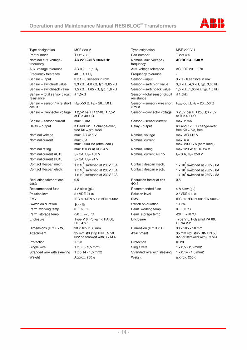
Type designation MSF 220 V Part number T 221736 Nominal aux. voltage / frequency
AC 220-240 V 50/60 Hz
Aux. voltage tolerance AC 0,9 ... 1,1 Us Frequency tolerance 48 ... 1,1 US Sensor – input 3 x 1 - 6 sensors in row Sensor – switch-off value 3,3 k�…4,0 k�, typ. 3,65 k� Sensor – switchback value 1,5 k�…1,65 k�, typ. 1,6 k� Sensor – total sensor circuit resistance
� 1,5k�
Sensor – sensor / wire short circuit
Rmin>50 �, Rk = 20…50 �
Sensor – Connector voltage � 2,5V bei R � 250�;� 7,5V at R � 4000�
Sensor – sensor current max. 2 mA Relay – output K1 and K2 = 1 change-over,
free K0 = n/o, freei Nominal voltage max. AC 415 V Nominal current max. 6 A
max. 2000 VA (ohm load ) Nominal rating max.120 W at DC 24 V Nominal current AC15 Ie= 2A, Ue= 400 V Nominal current DC13 Ie= 2A, Ue= 24 V Contact lifespan mech. 1 x 10
5 switched at 230V / 6A Contact lifespan electr. 1 x 10
5 switched at 230V / 6A 1 x 10
6 switched at 230V / 2A Reduction faktor at cos �0,3
0,5
Recommended fuse 4 A slow (gL) Polution level 2 / VDE 0110 EMV IEC 801/EN 50081/EN 50082 Switch on duration 100 % Perm. working temp. 0 ... 60 °C Perm. storage temp. -20 ... +70 °C Enclosure Type V 6, Polyamid PA 66,
UL 94 V-2 Dimensions (H x L x W) 90 x 105 x 58 mm Attachment 35 mm std strip DIN EN 50
022 or screwed with 3 x M 4 Protection IP 20 Single wire 1 x 0,5 - 2,5 mm2 Stranded wire with sleevíng 1 x 0,14 - 1,5 mm2 Weight Approx. 250 g
Type esignation MSF 220 VU Part number T 221735 Nominal aux. voltage / frequency
AC/DC 24…240 V
Aux. voltage tolerance AC / DC 20 ... 270 Frequency tolerance - Sensor – input 3 x 1 - 6 sensors in row Sensor – switch-off value 3,3 k�…4,0 k�, typ. 3,65 k� Sensor – switchback value 1,5 k�…1,65 k�, typ. 1,6 k� Sensor – total sensor circuit resistance
� 1,5k�
Sensor – sensor / wire short circuit
Rmin>50 �, Rk = 20…50 �
Sensor – connector voltage � 2,5V bei R � 250�;� 7,5V at R � 4000�
Sensor – sensor current max. 2 mA Relay - output K1 and K2 = 1 change-over,
free K0 = n/o, free Nominal voltage max. AC 415 V Nominal current max. 6 A
max. 2000 VA (ohm load ) Nominal rating max.120 W at DC 24 V Nominal current AC 15 Ie= 3 A, Ue= 250 V Contact lifespan mech. 1 x 10
5 switched at 230V / 6A Contact lifespan electr. 1 x 10
5 switched at 230V / 6A 1 x 10
6 switched at 230V / 2A Reduction factor at cos �0,3
0,5
Recommended fuse 4 A slow (gL) Polution level 2 / VDE 0110 EMV IEC 801/EN 50081/EN 50082 Switch on duration 100 % Perm. working temp. 0 ... 60 °C Perm. storage temp. -20 ... +70 °C Enclosure Type V 6, Polyamid PA 66,
UL 94 V-2 Dimension (H x B x T) 90 x 105 x 58 mm Attachment 35 mm std. strip DIN EN 50
022 or screwed with 3 x M 4 Protection IP 20 Single wire 1 x 0,5 - 2,5 mm2 Stranded wire with sleeving 1 x 0,14 - 1,5 mm2 Weight approx. 250 g
Operation and Maintenance Manual RESIBLOC® Transformers
- 15 -
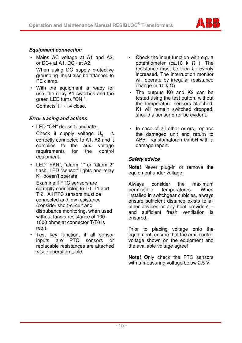
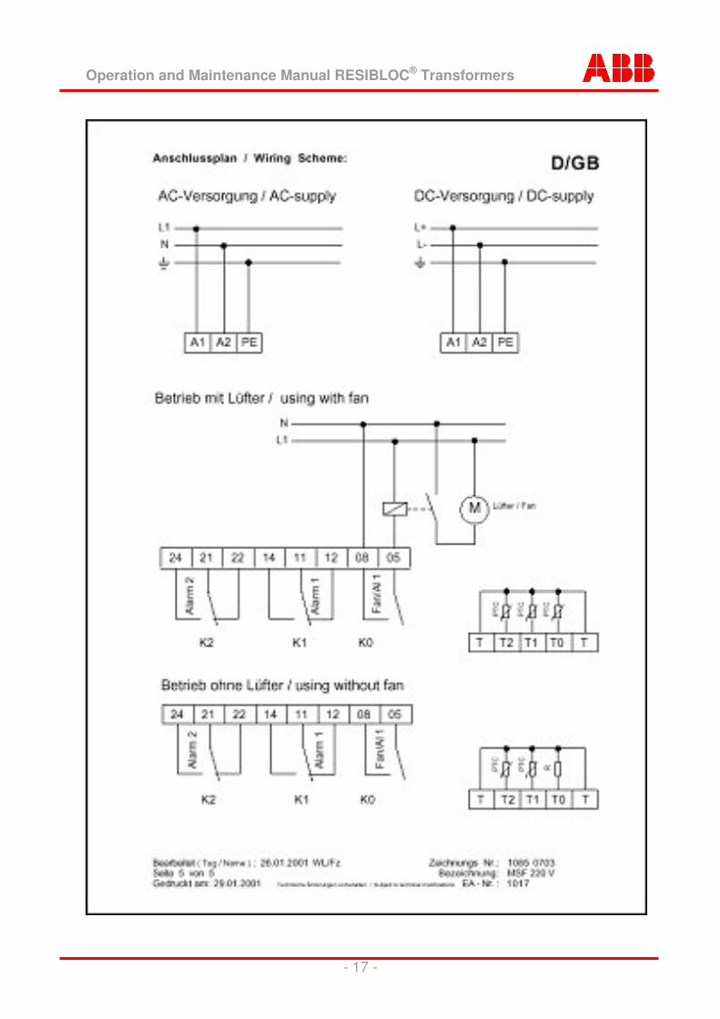
Equipment connection
• Mains AC voltage at A1 and A2, or DC+ at A1, DC - at A2.
When using DC supply protective grounding must also be attached to PE clamp.
• With the equipment is ready for use, the relay K1 switches and the green LED turns "ON ".
Contacts 11 - 14 close. Error tracing and actions
• LED "ON" doesn’t iluminate . Check if supply voltage US is
correctly connected to A1, A2 and it complies to the aux. voltage requirements for the control equipment.
• LED “FAN”, “alarm 1” or “alarm 2” flash, LED “sensor” lights and relay K1 doesn’t operate:
Examine if PTC sensors are correctly connected to T0, T1 and T 2. All PTC sensors must be connected and low resistance (consider short-circuit and distrubance monitoring, when used without fans a resistance of 100 - 1000 ohms at connector T/T0 is req.).
• Test key function, if all sensor inputs are PTC sensors or replacable resistances are attached > see operation table.
• Check the input function with e.g. a potentiometer (ca.10 k � ). The resistance must be then be evenly increased. The interruption monitor will operate by irregular resistance change (> 10 k �).
• The outputs K0 and K2 can be tested using the test button, without the temperature sensors attached. K1 will remain switched dropped, should a sensor error be evident.
• In case of all other errors, replace
the damaged unit and return to ABB Transfomatoren GmbH with a damage report.
Safety advice
Note! Never plug-in or remove the equipment under voltage. Always consider the maximum permissible temperatures. When installed in switchgear cubicles, always ensure sufficient distance exists to all other devices or any heat providers – and sufficient fresh ventilation is ensured. Prior to placing voltage onto the equipment, ensure that the aux. control voltage shown on the equipment and the available voltage agree! Note! Only check the PTC sensors with a measuring voltage below 2.5 V.
Operation and Maintenance Manual RESIBLOC® Transformers
- 16 -
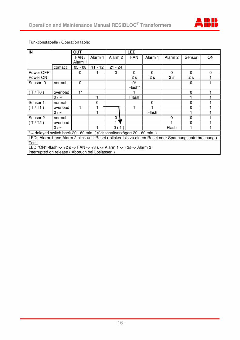
Funktionstabelle / Operation table: IN OUT LED FAN /
Alarm 1 Alarm 1 Alarm 2 FAN Alarm 1 Alarm 2 Sensor ON
contact 05 - 08 11 - 12 21 - 24 Power OFF 0 1 0 0 0 0 0 0 Power ON 2 s 2 s 2 s 2 s 1 Sensor 0 normal 0 0/
Flash* 0 1
( T / T0 ) overload 1* 1 0 1 0 / � 1 Flash 1 1 Sensor 1 normal 0 0 0 1 ( T / T1 ) overload 1 1 1 1 0 1 0 / � 1 Flash 1 1 Sensor 2 normal 0 0 0 1 ( T / T2 ) overload 1 1 0 1 0 / � 1 0 ( 1 ) Flash 1 1 * = delayed switch back 20 - 60 min. ( rückschaltverzögert 20 - 60 min. ) LEDs Alarm 1 and Alarm 2 blink until Reset ( blinken bis zu einem Reset oder Spannungsunterbrechung ) Test: LED "ON" -flash -> +2 s -> FAN -> +3 s -> Alarm 1 -> +3s -> Alarm 2 Interrupted on release ( Abbruch bei Loslassen )
Operation and Maintenance Manual RESIBLOC® Transformers
- 17 -
Operation and Maintenance Manual RESIBLOC® Transformers
- 18 -
8.2 Dial type thermometer with maximum indicator and 2 contacts Technical details
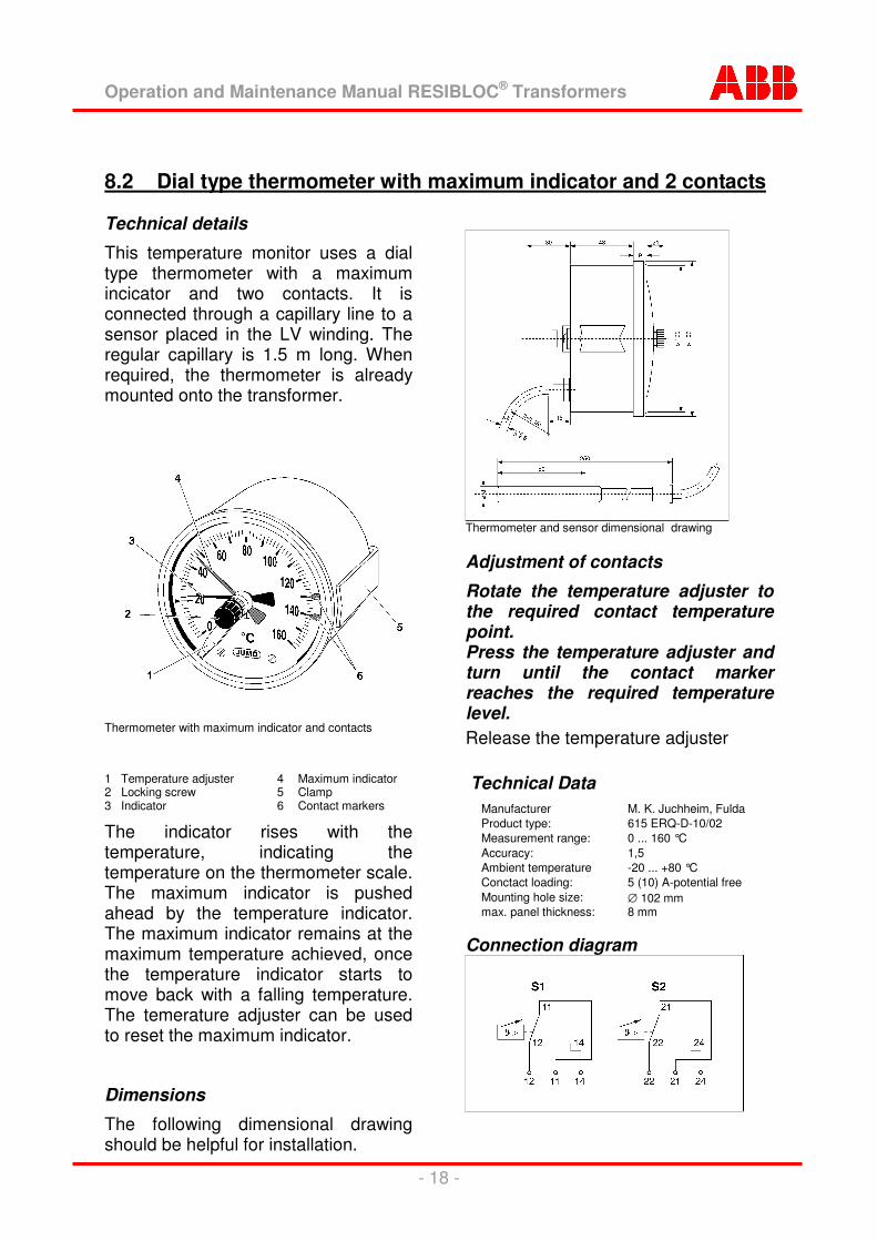
This temperature monitor uses a dial type thermometer with a maximum incicator and two contacts. It is connected through a capillary line to a sensor placed in the LV winding. The regular capillary is 1.5 m long. When required, the thermometer is already mounted onto the transformer.
Thermometer with maximum indicator and contacts 1 Temperature adjuster 4 Maximum indicator 2 Locking screw 5 Clamp 3 Indicator 6 Contact markers
The indicator rises with the temperature, indicating the temperature on the thermometer scale. The maximum indicator is pushed ahead by the temperature indicator. The maximum indicator remains at the maximum temperature achieved, once the temperature indicator starts to move back with a falling temperature. The temerature adjuster can be used to reset the maximum indicator.
Dimensions The following dimensional drawing should be helpful for installation.
Thermometer and sensor dimensional drawing Adjustment of contacts
Rotate the temperature adjuster to the required contact temperature point. Press the temperature adjuster and turn until the contact marker reaches the required temperature level. Release the temperature adjuster Technical Data
Manufacturer M. K. Juchheim, Fulda Product type: 615 ERQ-D-10/02 Measurement range: 0 ... 160 °C Accuracy: 1,5 Ambient temperature -20 ... +80 °C Conctact loading: 5 (10) A-potential free Mounting hole size: ∅ 102 mm max. panel thickness: 8 mm
Connection diagram
Operation and Maintenance Manual RESIBLOC® Transformers
- 19 -
8.3 PTC sensors, Pt100, etc..
Sensors arrangement
Should you need to replace the sensors for others, the replacement sensors to be installed must be insulated. Sensors that are not insulated and placed in the cooling channels will cause a short-circuit!
Firmly attach the sensors into a secondary (low voltage) cooling channel or support them directly above.
For the sake of safety always inform ABB Transformatoren GmbH, Brilon every time other sensors are to be used.
9 Cross-flow cooling fans Technical details
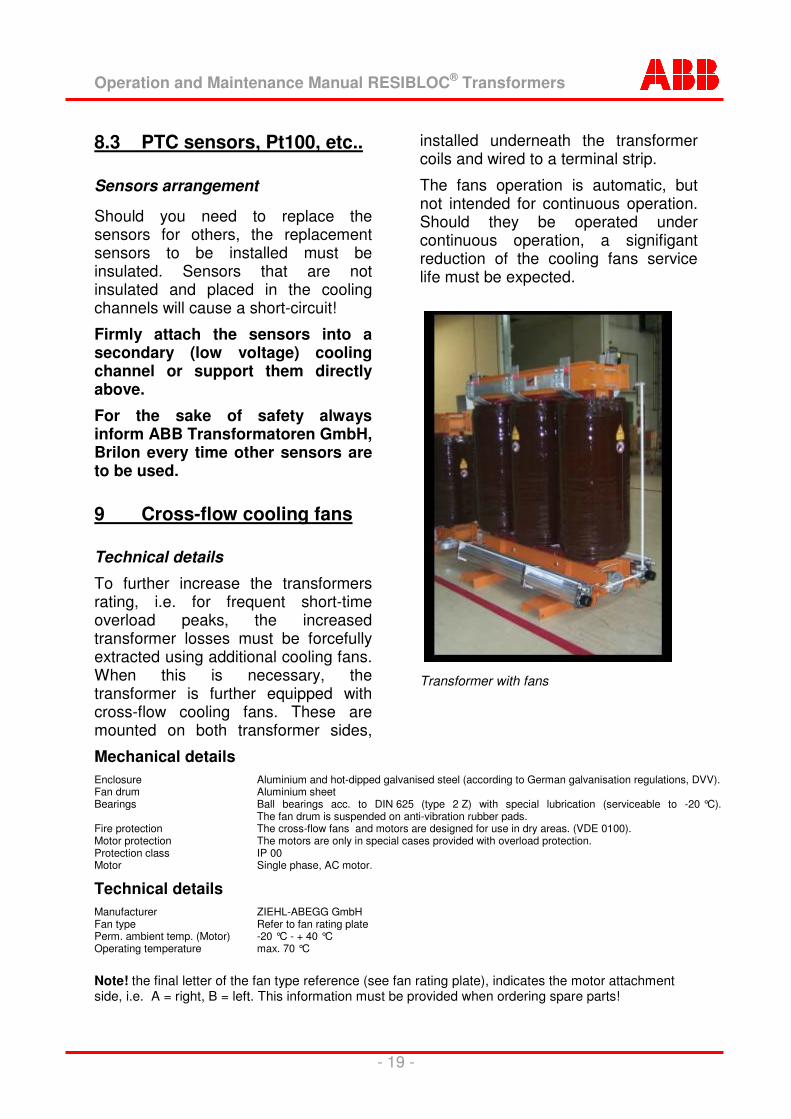
To further increase the transformers rating, i.e. for frequent short-time overload peaks, the increased transformer losses must be forcefully extracted using additional cooling fans. When this is necessary, the transformer is further equipped with cross-flow cooling fans. These are mounted on both transformer sides,
installed underneath the transformer coils and wired to a terminal strip.
The fans operation is automatic, but not intended for continuous operation. Should they be operated under continuous operation, a signifigant reduction of the cooling fans service life must be expected.
Transformer with fans
Mechanical details Enclosure Aluminium and hot-dipped galvanised steel (according to German galvanisation regulations, DVV). Fan drum Aluminium sheet Bearings Ball bearings acc. to DIN 625 (type 2 Z) with special lubrication (serviceable to -20 °C).
The fan drum is suspended on anti-vibration rubber pads. Fire protection The cross-flow fans and motors are designed for use in dry areas. (VDE 0100). Motor protection The motors are only in special cases provided with overload protection. Protection class IP 00 Motor Single phase, AC motor.
Technical details Manufacturer ZIEHL-ABEGG GmbH Fan type Refer to fan rating plate Perm. ambient temp. (Motor) -20 °C - + 40 °C Operating temperature max. 70 °C
Note! the final letter of the fan type reference (see fan rating plate), indicates the motor attachment side, i.e. A = right, B = left. This information must be provided when ordering spare parts!
ABB Transformatoren GmbH Werk Brilon Bremecketal D-59929 Brilon Telefon:+49 (0) 29 61 / 7 97-0 Telefax:+49 (0) 29 61 / 7 97-290
Doc
umen
t Num
ber:
1LD
E00
0005
P
ublis
her:
AB
B T
rans
form
ator
en G
mbH
, Bre
mec
keta
l, 59
929
Bril
on, G
erm
any