Embed Size (px)
Citation preview

Power transmission
Schaberweg 30-38 Telephone +49 6172 275-0 Fax +49 6172 275-275
www.ringspann.com [email protected] 61348 Bad Homburg
Germany
Installation and Operating Instructions for
Brake Calliper HS 120 FHM
E 09.753e

Installation and Operating Instructions
for brake calliper HS 120 FHM
spring activated - hydraulically released
E 09.753e
issue: 30.06.2017 Version: 1 drawn: BAHS Checked: EISF pages: 30 Page: 2
IMPORTANT
Please read these instructions carefully before installing and operating the product. Your particular attention is drawn to the notes on safety. These installation and operating instructions are valid on condition that the product meets the selection criteria for its proper use. Selection and design of the product is not the subject of these installation and operating instructions. Disregarding or misinterpreting these installation and operating instructions invalidates any product liability or guarantee by RINGSPANN; the same applies if the product is taken apart or changed.
These installation and operating instructions should be kept in a safe place and should accompany
the product if it is passed on to others -either on its own or as part of a machine- to make it
accessible to the user.
SAFETY NOTICE
Installation and operation of this product should only be carried out by skilled personnel.
Repairs may only be carried out by the manufacturer or accredited RINGSPANN agents.
If a malfunction is indicated, the product or the machine into which it is installed, should be stopped immediately and either RINGSPANN or an accredited RINGSPANN agent should be informed.
Switch off the power supply before commencing work on electrical components.
Rotating machine elements must be protected by the purchaser to prevent accidental contact. Supplies abroad are subject to the safety laws prevailing in those countries.
This is a translation of the German original version!
In case of inconsistencies between the German and English version of this installation and operating instruction, the German version shall prevail.

Installation and Operating Instructions
for brake calliper HS 120 FHM
spring activated - hydraulically released
E 09.753e
issue: 30.06.2017 Version: 1 drawn: BAHS Checked: EISF pages: 30 Page: 3
Contents
1. General notes
1.1 General safety instructions 1.2 Special safety instructions
2. Design and function / parts list
2.1 Function 2.2 Identification 2.3 Drawing and parts list
3. Intended use
4. Impermissible use
5. Condition as delivered
6. Handling and storage
7. Technical prerequisite for reliable operation
8. Installing the RINGSPANN brake
8.1 General instructions regarding assembly and installation 8.2 Assembly description 8.3 Setting/adjusting of the friction pads distance 8.4 Assembly of the screw connection and bleeding of the brake 8.5 Connecting the signal cable (optional)
9. Start-up
10. Disassembling the brake
11. Maintenance
11.1 General maintenance 11.2 Permissible friction lining wear and exchanging of the friction pads 11.3 Exchanging seals, wipers and piston seals
12. Accessories: Sensor for operating state monitoring
12.1 Mounting and connection of inductive proximity switch for position monitoring 12.2 Mounting and connection of inductive proximity switch for pad wear monitoring

Installation and Operating Instructions
for brake calliper HS 120 FHM
spring activated - hydraulically released
E 09.753e
issue: 30.06.2017 Version: 1 drawn: BAHS Checked: EISF pages: 30 Page: 4
1. General notes
1.1 General safety instructions
Read these installation/operating instructions carefully before putting the brake calliper into operation. Consider these instructions as well as the drawings in the individual sections. All work with and on the brake is to be carried out taking into account that "safety is top priority". Switch the drive unit off before carrying out work on the brake. Rotating parts (e.g. brake disc) must be secured by the operator against unintentional touching. 1.2 Special safety instructions
2. Design and function / parts list
2.1 Function
The brake is a machine element with which accelerated masses can be safely slowed down. In combination with a brake disc, you have a complete brake for the effective safeguarding of machines and systems. Thanks to its universal design, it fulfils the following functions:
As a holding brake, it prevents a stationary shaft from starting unintentionally.
As a stopping brake, it brings a rotating shaft to a halt.
As a control brake, it maintains a particular tensile force within the material. The braking force is produced with spring force, and the brake is opened by means of hydraulic pressure.
Life-threatening danger!
When assembling, operating and maintaining the brake it is to be
ensured that the entire drive train is secured against being switched
on unintentionally. Rotating parts can cause severe injury. Rotating
parts (e.g. brake disc) must be secured by the operator against
unintentional touching.

Installation and Operating Instructions
for brake calliper HS 120 FHM
spring activated - hydraulically released
E 09.753e
issue: 30.06.2017 Version: 1 drawn: BAHS Checked: EISF pages: 30 Page: 5
2.2 Identification
These operating instructions apply for:
The design HS 120 FHM.
The mounting onto vertical brake discs (in case of horizontal shaft) as well as horizontal brake discs.
The design with and without an inductive proximity switch.
Different friction materials as well as for friction pads with signal cable.
There is a type plate on the brake with a 16-digit article number. The exact design of the brake is defined by this article number only.
As well as these instructions, please also consider the catalogue data for the brake at www.ringspann.com and the drawings in the individual sections.
2.3 Drawing and parts list
Brake calliper HS 120 FHM
Fig. 2.1
Installation and Operating Instructions
for brake calliper HS 120 FHM
spring activated - hydraulically released
E 09.753e
issue: 30.06.2017 Version: 1 drawn: BAHS Checked: EISF pages: 30 Page: 6
Fig. 2.2
Bild 2.1

Installation and Operating Instructions
for brake calliper HS 120 FHM
spring activated - hydraulically released
E 09.753e
issue: 30.06.2017 Version: 1 drawn: BAHS Checked: EISF pages: 30 Page: 7
Fig. 2.3
Fig. 2.4

Installation and Operating Instructions
for brake calliper HS 120 FHM
spring activated - hydraulically released
E 09.753e
issue: 30.06.2017 Version: 1 drawn: BAHS Checked: EISF pages: 30 Page: 8
Part Designation Quantity
1 Friction pad set HW(S) 120 1
2 Brake housing HW 120 FHM 1
3 Pressure spring SA 18 4
4 Turcon Stepseal 2K RSK301200 1
5 Turcon Excluder 2 WE3201200 1
6 Holding plate H120 2
7 Piston HW 120 FHM 1
8 Hexagon nut M10 DIN 34-8.8 galvanised 8
9 Threaded piece M10x145 A2 4
10 Holding plate 2
11 Disc B21 DIN 125-ST galvanised 8
12 Hexagon screw M20x70 DIN 931-10.9 8
13 Base body HS 120 1
14 Hexagon screw M30x200 DIN 931-8.8 6
15 Cylinder screw M10x40 ISO 4762 4
16 Pressure spring RDF-2055 4
17 Hexagon screw M12x50 DIN 933-8.8 2
18 Hexagon nut M12 DIN 934-8 2
19 Slide bush RS 125 80x85x22.5 2
20 Base holder for HS 120 1
21 Stopper plug R ¼“ KAPSTO GPN 700 3
22 Slide bush KGGM 50 80x85x60 2
23 Disc 10 DIN 125-ST galvanised 4
24 Tension spring 28.2x76.4x3.2 galvanised, Z-169I 2
25 Half-length grooved pin with gorge 2
26 Disc spring 125x64x6 H+S=9.6, acc. to design max. 21
27 Guide disc 104x125 acc. to design max. 7
28 Turcon-Stepseal 2K RSK301600 1
29 Spring seating body for HW 120 FHM 1
30 O-ring 160x5 1
31 Disc A 24 GN6339 6339-24,5-44-5-BT 1
32 Hexagon screw M 22x1,5x60 DIN 961 1
33 Intermediate plate HS 120 W=30 for wide brake discs Option
34 Washer 31 DIN 125-B 6

Installation and Operating Instructions
for brake calliper HS 120 FHM
spring activated - hydraulically released
E 09.753e
issue: 30.06.2017 Version: 1 drawn: BAHS Checked: EISF pages: 30 Page: 9
Fig. 2.5
Fig. 2.6

Installation and Operating Instructions
for brake calliper HS 120 FHM
spring activated - hydraulically released
E 09.753e
issue: 30.06.2017 Version: 1 drawn: BAHS Checked: EISF pages: 30 Page: 10
Part Designation Quantity
20.1 Base plate HS 120 1
20.2 Holding bolt HS 120 2
20.3 Holding disc HS 120 2
20.4 Cylinder screw M8x30 ISO 4762 4
20.5 Half-length grooved pin with gorge 2
20.6 Clamping sleeve 14x50 2
3. Intended use
The brake calliper may only be used with a maximum oil pressure of 200 bar and in accordance with the technical data.
The brake has been designed for use as a holding, control and stopping brake. Use for any other purpose will be deemed improper. RINGSPANN shall not be liable for any damage caused by improper use; the risk shall be borne by the user alone.
4. Impermissible use
It is not permissible to operate the brake with a higher pressure than given in the technical data or with other media. Unauthorised constructional changes to the brake are also not allowed. RINGSPANN shall not be liable for any damage caused by improper use; the risk shall be borne by the user alone.
5. Condition as delivered
The brake calliper is supplied tested. The test pressure is 200 bar The brake calliper is delivered ready to install. The brake cylinder is fixed in open position by assembly securing screw M 22x1.5x60 (item 32).
6. Handling and storage
The technical data of the brake such as air pressure, clamping force, air volume, dimensions and weight are shown on the catalogue pages for the brake. The current data can also be found on the RINGSPANN website www.ringspann.com. For the transport and handling 3xM12 threads are attached to the brake..
The brake is delivered in preserved condition and can be stored for 12 months in an enclosed and dry place. It is to be made sure that no condensation develops. Damp storage rooms are not suitable. If storing the brake for a period longer than 12 months, as well as after any transport, the brake must be activated once in order to prevent the seals from getting stuck down.
Installation and Operating Instructions
for brake calliper HS 120 FHM
spring activated - hydraulically released
E 09.753e
issue: 30.06.2017 Version: 1 drawn: BAHS Checked: EISF pages: 30 Page: 11
7. Technical prerequisite for reliable operation
Fastening the brake to stable and low-vibration machine parts will ensure quiet braking without creaking.
8. Installing the RINGSPANN brake
8.1 General instructions regarding assembly and installation
Before installing the brake, the brake disc must be cleaned with alcohol (e.g. spirit (ethanol) or isopropyl alcohol) or with water-based tenside solutions (soapy water or the like).
If cleaning the brake disc with a diluent, acetone or brake cleaning agent, it must be ensured that these agents and no residues of these agents come into direct contact with the friction blocks. This must be ensured for pure holding brakes in particular, since no dynamic braking takes place that would remove any diluent residues from the brake disc.
Important!
Residues from oil and anti-rust agent considerably reduce the coefficient of friction and thus also the braking and holding torque!
8.2 Assembly description
The standard brake calliper is fastened to the machine part with 2 M36 screws 10.9, tightening torque 2450 Nm, lubricated with Molykote MoS2. (The screws are not included in the delivery).
Important!
Hydraulic pressure must not be applied to the brake calliper during assembly.
Before assembly it is to be checked whether the mounting surface is even and the concentricity between the brake disc and mounting surface is within a tolerance of 0.3 mm. Examine the axial movement of the brake disc. The axial movement must not be greater than ± 0.3 mm. The maximum permissible lateral run-out of the brake disc is 0.1 mm. A greater lateral run-out can cause the brake unit to rattle and shake.

Installation and Operating Instructions
for brake calliper HS 120 FHM
spring activated - hydraulically released
E 09.753e
issue: 30.06.2017 Version: 1 drawn: BAHS Checked: EISF pages: 30 Page: 12
Fig. 8.1 The connecting plate for the brake as well as the brake disc must be checked for dimensional accuracy. For this purpose, the connection dimensions shown on the catalogue data sheet or installation drawing are to be checked. The standard clearance is 140 mm +/-1 mm.
Important!
Check whether the brake disc can be freely rotated.
Information!
To make assembly easier, you can fix the position of the brake with just one screw to start with, before then slewing the brake far enough for the second screw to be mounted also.

Installation and Operating Instructions
for brake calliper HS 120 FHM
spring activated - hydraulically released
E 09.753e
issue: 30.06.2017 Version: 1 drawn: BAHS Checked: EISF pages: 30 Page: 13
8.3 Setting/adjusting of the friction pads distance The adjustment of the friction pads distance is carried out after the brake calliper has been assembled. It is done by setting/ adjusting using the setting/ adjusting screw (see Fig. 8.2.) The distance from both sides of the friction pads to the brake disc should be approx. 1 mm when new. At the time of wear adjustment, one side is adjusted.
Important!
During assembly it is to be ensured that the brake blocks are centrally aligned and make full-face contact with the brake disc. The distance from both sides of the brake linings to the brake disc should be approx. 1 mm when new.
Installation and Operating Instructions
for brake calliper HS 120 FHM
spring activated - hydraulically released
E 09.753e
issue: 30.06.2017 Version: 1 drawn: BAHS Checked: EISF pages: 30 Page: 14
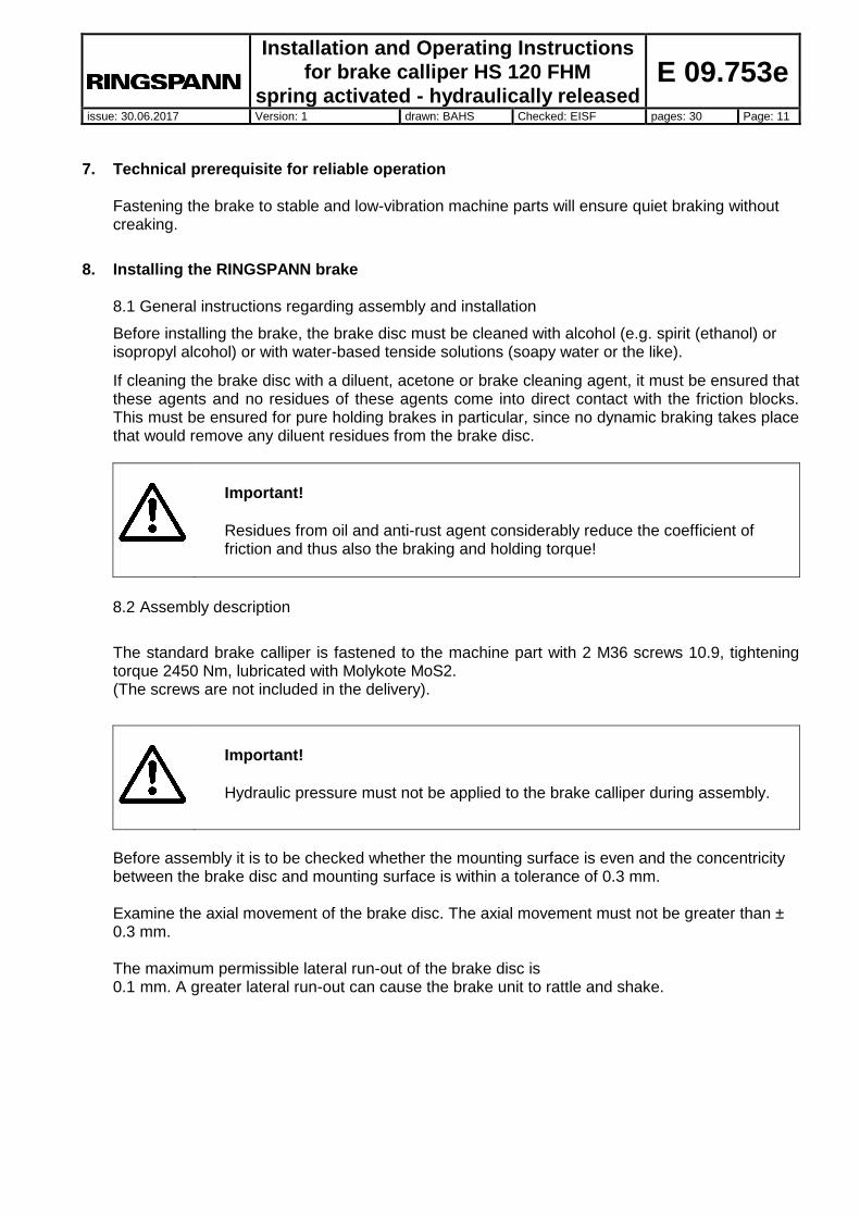
Fig. 8.2
After the adjustment/readjustment procedure, lock the hexagon nuts (see Fig. 8.2) So that there is enough space for changing a friction block, there should be at least 300 mm of free space on one side of the brake, in order for the friction block to be easily disassembled and assembled.
Important!
The adjustmentprocess must be made after installation and replacment oft he brake pad.

Installation and Operating Instructions
for brake calliper HS 120 FHM
spring activated - hydraulically released
E 09.753e
issue: 30.06.2017 Version: 1 drawn: BAHS Checked: EISF pages: 30 Page: 15
8.4 Assembly of the screw connection and bleeding of the brake
Important!
Flexible hydraulic hoses are to be used for the pressure line and leakage oil line connection so as to not inhibit the movements of the brake.
The connection is made at one of the two pressure oil connections; the second borehole serves as a bleeder hole. Attach the leakage oil line (if available) or use a collection container for each brake calliper in order to be able to locate an oil leakage easily.
Fig. 8.3

Installation and Operating Instructions
for brake calliper HS 120 FHM
spring activated - hydraulically released
E 09.753e
issue: 30.06.2017 Version: 1 drawn: BAHS Checked: EISF pages: 30 Page: 16
Important!
It must be ensured that the friction blocks do not grind on the brake disc while the brake calliper is released.
Assemble a mini measuring connection or an automatic bleeding system at the bleeder hole. The screwed sealing plug is to be removed beforehand for this purpose.
If carrying out initial assembly, exchanging the seals or performing other work on the hydraulics, the hydraulic system must be bled. If the system is designed for hydraulic oil circulation, the hydraulic system can alternatively be bled through circulating hydraulic oil.
Important!
Any oil that has escaped must be completely removed. Leakages are to be eliminated immediately.
The following are to be checked to ensure firm screwing and connection:
Brake calliper at the machine part
The following are to be inspected for tightness:
Screwings and connections
Important!
The brake calliper has two pressure oil connections marked with P1 and P2 size G ¼ (Whitworth pipe thread DIN ISO 228-1) and a leakage oil connection marked with L size G ¼ (Whitworth pipe thread DIN ISO 228-1). The hydraulic system must never be operated with a higher pressure than permitted. The maximum operating pressure is 200 bar.
Oil volume: Per 1 mm of piston stroke = 10 cm3
Max. oil volume (at max. friction lining wear) = 160 cm3.
Alloyed mineral oil of HLP group in accordance with DIN 51525 or in accordance with API classification SC, SD, SE can be used as hydraulic fluid.

Installation and Operating Instructions
for brake calliper HS 120 FHM
spring activated - hydraulically released
E 09.753e
issue: 30.06.2017 Version: 1 drawn: BAHS Checked: EISF pages: 30 Page: 17
Information!
The service life of the brake system will extend depending on how high the purity of the oil is.
8.5 Connecting the signal cable (optional)
Attach the signal cable (e.g. via a signal lamp) to a 24V control voltage. If the maximum friction lining abrasion limit is reached, contact with the neutral conductor will be made and the signal lamp will light up.
Fig. 8.4
9. Start-up
Only full-face contact of the two friction pads (item 1) on the brake disc as well as a rapid heating of the friction linings to approx. 200°C will ensure an optimal braking effect. It is therefore necessary to brake several times and for a short duration when the brake disc is rotating.
Important!
If the brakes are used as holding brakes, then the braking torques indicated in the catalogue will not be reached. Reductions of up to 50% of the braking torque are possible.

Installation and Operating Instructions
for brake calliper HS 120 FHM
spring activated - hydraulically released
E 09.753e
issue: 30.06.2017 Version: 1 drawn: BAHS Checked: EISF pages: 30 Page: 18
Important!
If breaking-in is not possible, the braking torques specified in our leaflet (46) will not be reached. Reductions of up to 50% are possible.
10. Disassembling the brake
Life-threatening danger!
When disassembling the brake it is to be ensured that the entire drive train
is secured against being switched on unintentionally. Rotating parts can
cause severe injury. Rotating parts (e.g. brake disc) must be secured by
the operator against unintentional touching.
Important! Open the brake with oil pressure and secure the open position with the securing screw, hexagon screw M 22x1.5x60 DIN 961 (item 32). Before disassembly, the system is to be depressurised. Drain the hydraulic oil completely.
Important! Secure the brake for disassembly.
Separate the hydraulic lines from the brake. Secure the brake for disassembly. Remove the M36 screws that serve for fastening the brake. The brake can now be removed from the mounting surfaces.
11. Maintenance
11.1 General maintenance
Depending on how much the brake is used in operation, maintenance is to be carried out on it at intervals of 4 weeks to once a year.
The following is to be carried out when performing maintenance:
Check the friction pads for wear.

Installation and Operating Instructions
for brake calliper HS 120 FHM
spring activated - hydraulically released
E 09.753e
issue: 30.06.2017 Version: 1 drawn: BAHS Checked: EISF pages: 30 Page: 19
Check the screw connection of the brake calliper to the machine part and also check the
firmness of the screw connection of the holding plates.
Check the hydraulic lines and connections for tightness.
Check the sealing system of the brake pistons for tightness by inspecting the leakage oil lines. If there is oil in the leakage oil line, the seals are to be exchanged.
Respect the oil changing interval! Renew the mineral oil after 8000 hours of operation or once a year.
Clean the bearing and sliding points.
Check the bearing and sliding points. If necessary, oil or grease the bearing and sliding points in the area of the guide bushes (item 19 and item 22).
Important!
The friction pads must not come into contact with the lubricant.
Important!
The friction pads must not come into contact with the hydraulic oil.
11.2 Permissible friction lining wear and exchanging of the friction pads
Life-threatening danger! Friction pads may only be changed when the system or the work machine is stationary!
Important! The friction lining has a thickness of 30 mm when new. After 8 mm of abrasion or a residual lining thickness of 22 mm, the friction blocks are to always be exchanged in pairs. Only original RINGSPANN friction pads may be used.
Before exchanging the friction pads (item 1), ensure that the mass held by the brake is secured against moving, since parts of the brake need to be loosened for this purpose.

Installation and Operating Instructions
for brake calliper HS 120 FHM
spring activated - hydraulically released
E 09.753e
issue: 30.06.2017 Version: 1 drawn: BAHS Checked: EISF pages: 30 Page: 20
Important! Ensure that there is no oil pressure at the brake calliper before exchanging the friction pads.
Before exchanging the friction pads ensure that the securing screw M22x1.5 x60 (item 32) is securing the open position and that there is no oil pressure at the brake calliper. Disassemble one of the two holding plates in each case (item 6 and 10, Fig. 11.1) on one side. The wear adjustment screws M12x50 (item 17) are to be reset before changing the friction pad. Loosen the hexagon nuts M10 (item 8) and remove the 4 threaded pieces M10x145 (item 9) with the pressure springs (item 3) and on the other side the cylinder screws M10x40 (item 15). Note that the cylinder screws are slightly pre-loaded by the pressure springs (item 16).
Important! Note that the cylinder screws are slightly pre-loaded by the pressure springs
Exchange the friction pads (item 1) Refasten the friction pads with the 4 threaded pieces M10x145 (item 9), the 4 pressure springs (item 3) and the 8 hexagon nuts M10 (item 8). The pressure springs must be pre-loaded by approx. 8 mm and then locked with the hexagon nuts M10 (item 8). The threaded pieces are to be secured with Loctite 243 and are to be tightened with a maximum tightening torque of 10 Nm. On the other side, fasten the cylinder screws M10x40 (item 15), the disc (item 23) and the pressure springs (item 16). The screws are to be secured with Loctite 243 and are to be tightened with a maximum tightening torque of 10 Nm.
Installation and Operating Instructions
for brake calliper HS 120 FHM
spring activated - hydraulically released
E 09.753e
issue: 30.06.2017 Version: 1 drawn: BAHS Checked: EISF pages: 30 Page: 21
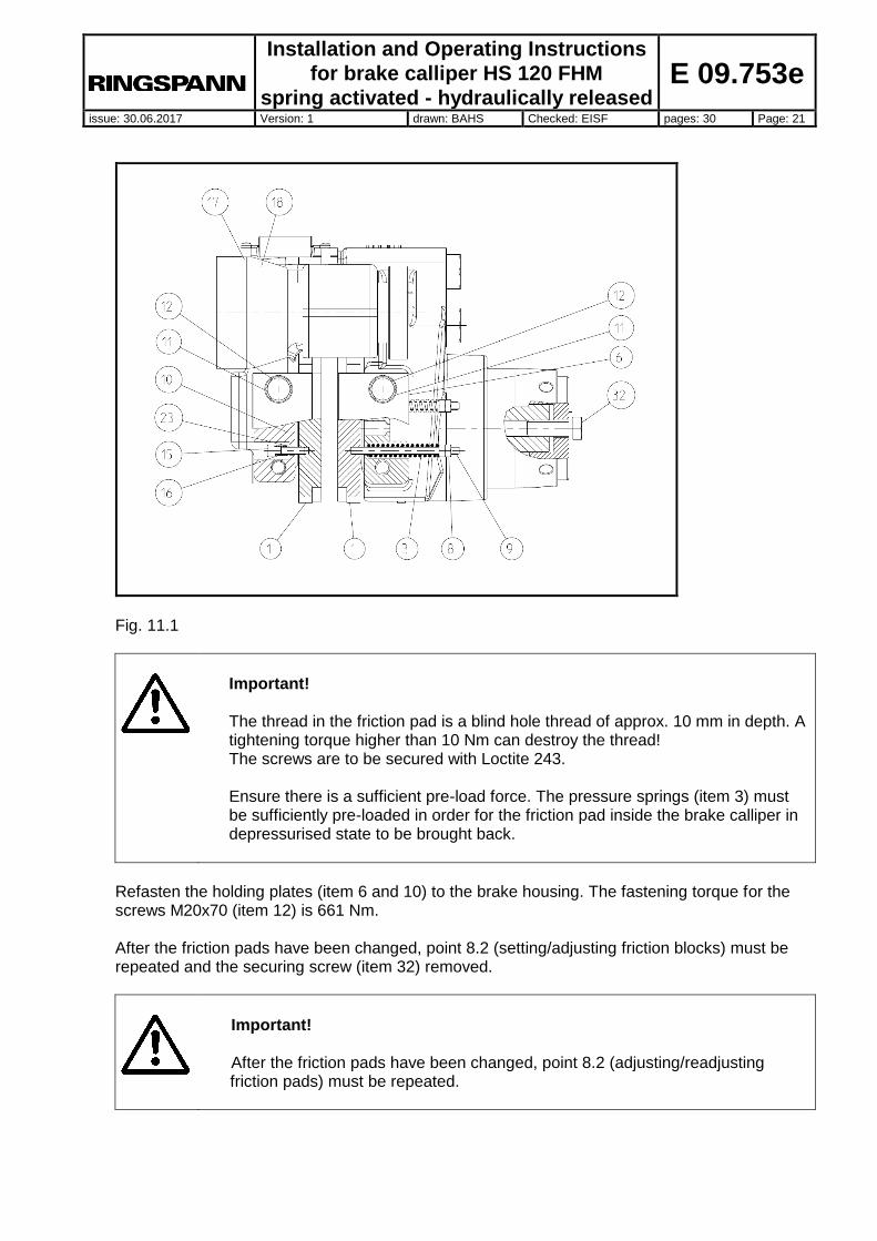
Fig. 11.1
Important! The thread in the friction pad is a blind hole thread of approx. 10 mm in depth. A tightening torque higher than 10 Nm can destroy the thread! The screws are to be secured with Loctite 243. Ensure there is a sufficient pre-load force. The pressure springs (item 3) must be sufficiently pre-loaded in order for the friction pad inside the brake calliper in depressurised state to be brought back.
Refasten the holding plates (item 6 and 10) to the brake housing. The fastening torque for the screws M20x70 (item 12) is 661 Nm. After the friction pads have been changed, point 8.2 (setting/adjusting friction blocks) must be repeated and the securing screw (item 32) removed.
Important! After the friction pads have been changed, point 8.2 (adjusting/readjusting friction pads) must be repeated.

Installation and Operating Instructions
for brake calliper HS 120 FHM
spring activated - hydraulically released
E 09.753e
issue: 30.06.2017 Version: 1 drawn: BAHS Checked: EISF pages: 30 Page: 22
11.3 Exchanging seals, wipers and piston seals
Life-threatening danger! The seals may only be changed when the system (or the work machine) is stationary!
Important! Ensure that there is no oil pressure at the brake calliper. Note the manufacturer's instructions for handling solvents.
The greatest possible cleanliness is to be ensured when working on the hydraulic system. Each part must be cleaned in solvent, dried and stored in a dust-proof place. Dirt shortens the service life of the seals considerably. Check the surfaces of the brake housings and brake pistons. Damages on the surface can destroy the seal immediately.
Disassemble the upper half of the brake calliper by loosening the 6 screws M30x200 (item 14).
Disassemble the half of the brake calliper. Loosen the hexagon nuts M10 (item 8) and remove the pressure springs and the friction pad as well as the 4 threaded pieces M10x145 (item 9). Note that the threaded pieces are slightly pre-loaded by the pressure springs (item 8). Remove the spring seating body for HW 120 FHM (item 29).
Important! Consider and remember the arrangement of disc springs and shim rings for assembly.
Remove the shim rings and the disc springs. Close up one pressure oil connection on the brake calliper half and attach a hydraulic hand pump onto the second pressure oil connection. Hold the brake housing (item 2) tight or clamp it. Squeeze the brake pistons (item 7) out using the hand pump. Make sure that the brake piston is squeezed evenly out of the brake housing (item 2).
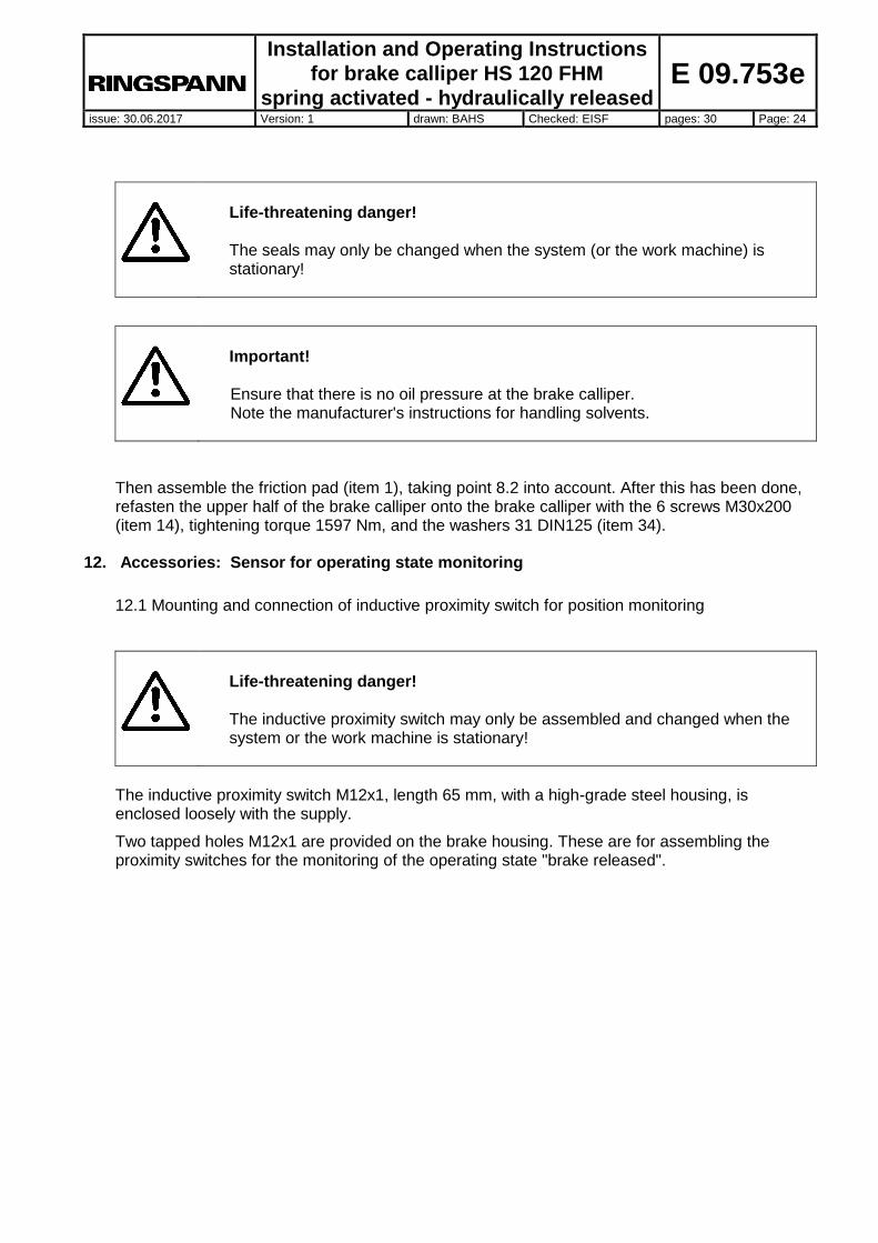
Remove the Turcon Excluder 2 (item 5), then the Turcon Stepseal 2K (item 4) and item 28, Turcon Stepseal 2K RSK301600, from the brake housing (item 2). Insert the new seal into the brake housing. In doing so, ensure the correct fitting position of the seal (see Fig. 11.3). This should only be carried out by hand, so that the sealing edge is not damaged. To make fitting easier, the seal can be bent into a kidney shape and placed into the groove. Slightly oil the seal. Push the piston in with a press or, using a plastic hammer, hit it centrically into the cylinder borehole until it comes to a stop. Then reassemble the disc springs, shim rings and
Installation and Operating Instructions
for brake calliper HS 120 FHM
spring activated - hydraulically released
E 09.753e
issue: 30.06.2017 Version: 1 drawn: BAHS Checked: EISF pages: 30 Page: 23
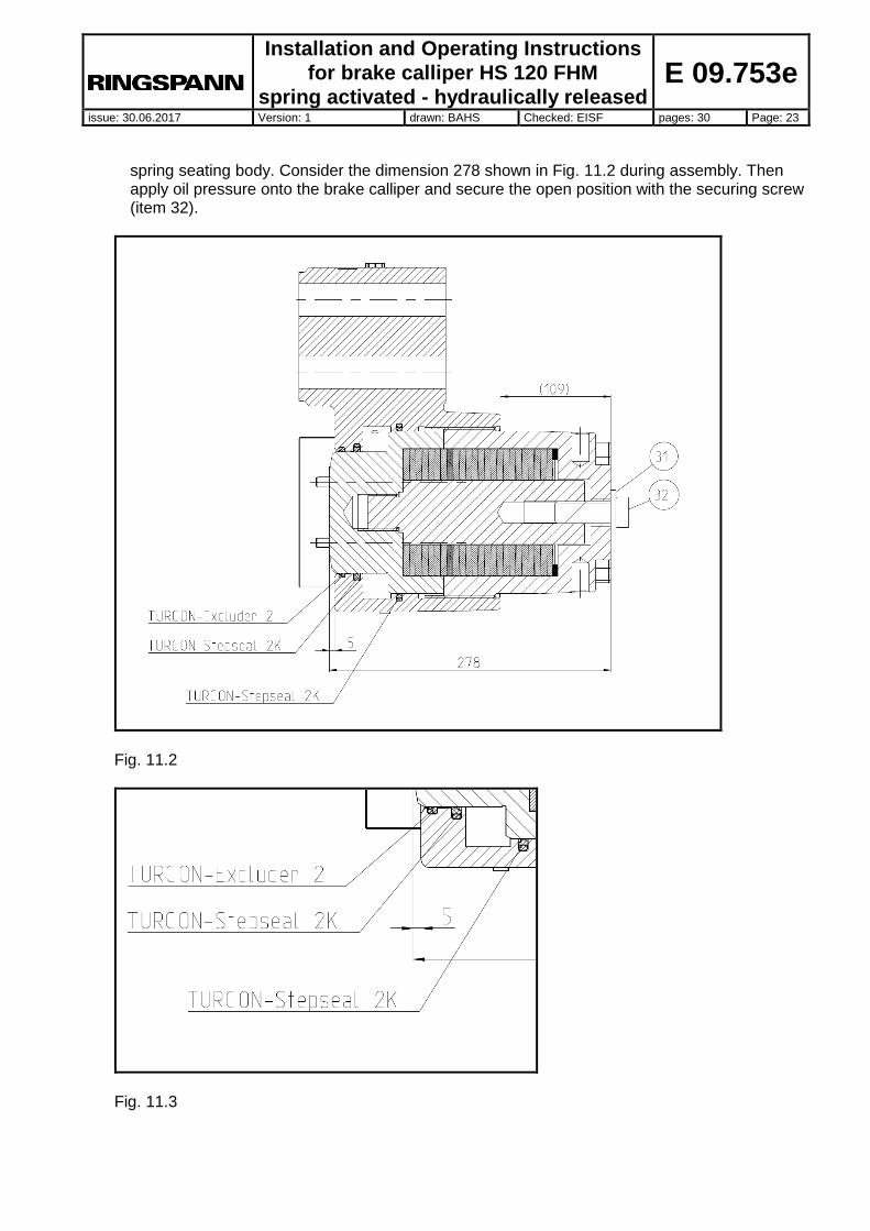
spring seating body. Consider the dimension 278 shown in Fig. 11.2 during assembly. Then apply oil pressure onto the brake calliper and secure the open position with the securing screw (item 32).
Fig. 11.2
Fig. 11.3
Installation and Operating Instructions
for brake calliper HS 120 FHM
spring activated - hydraulically released
E 09.753e
issue: 30.06.2017 Version: 1 drawn: BAHS Checked: EISF pages: 30 Page: 24
Life-threatening danger! The seals may only be changed when the system (or the work machine) is stationary!
Important! Ensure that there is no oil pressure at the brake calliper. Note the manufacturer's instructions for handling solvents.
Then assemble the friction pad (item 1), taking point 8.2 into account. After this has been done, refasten the upper half of the brake calliper onto the brake calliper with the 6 screws M30x200 (item 14), tightening torque 1597 Nm, and the washers 31 DIN125 (item 34).
12. Accessories: Sensor for operating state monitoring
12.1 Mounting and connection of inductive proximity switch for position monitoring
Life-threatening danger! The inductive proximity switch may only be assembled and changed when the system or the work machine is stationary!
The inductive proximity switch M12x1, length 65 mm, with a high-grade steel housing, is enclosed loosely with the supply.
Two tapped holes M12x1 are provided on the brake housing. These are for assembling the proximity switches for the monitoring of the operating state "brake released".

Installation and Operating Instructions
for brake calliper HS 120 FHM
spring activated - hydraulically released
E 09.753e
issue: 30.06.2017 Version: 1 drawn: BAHS Checked: EISF pages: 30 Page: 25
Fig. 12.1
Switching function: PNP (normally open contact) Switching distance: 2 mm flush Operating voltage: 10....30 V DC Operating current: 0...200 mA Idle current: < or = 17 mA Residual current: < or = 0.5 mA Voltage drop: < or = 3 V Short-circuit protection: Synchronising Reverse polarity protection: Yes Switching display: Multi-hole LED Temp. range: -25 to +70°C Type of protection: IP 67 Connection type: V1 appliance plug Housing: High-grade steel
Connection diagram of the inductive proximity switch
Fig. 12.2

Installation and Operating Instructions
for brake calliper HS 120 FHM
spring activated - hydraulically released
E 09.753e
issue: 30.06.2017 Version: 1 drawn: BAHS Checked: EISF pages: 30 Page: 26
Information! The inductive proximity switch is to be arranged in such a way that it is activated in depressurised state (the LED at the inductive proximity switch shines). If the brake is activated, the piston moves out of the housing and pushes the friction block onto the brake disc. The inductive proximity switch is then no longer activated. The LED at the inductive proximity switch goes out.
Work sequence for mounting, or in the case that exchanging the inductive proximity switch is necessary with a switching gap of 2 mm:
Assemble the inductive proximity switch when the brake is pressurised.
Screw the inductive proximity switch into the brake housing until there is a distance of approx. 1 mm between the inductive proximity switch and the back of the friction block.
Secure this position with the counter nut.
Attach the inductive proximity switch. The LED of the inductive proximity switch should shine.
Test for proper functioning by repeatedly activating the brake.
Fig. 12.3

Installation and Operating Instructions
for brake calliper HS 120 FHM
spring activated - hydraulically released
E 09.753e
issue: 30.06.2017 Version: 1 drawn: BAHS Checked: EISF pages: 30 Page: 27
Important!
Follow the exact work steps described, since otherwise the inductive proximity switch could get damaged.
12.2 Mounting and connection of inductive proximity switch for pad wear monitoring
Life-threatening danger! The inductive proximity switch may only be assembled and changed when the system or the work machine is stationary! The inductive proximity switch will be damaged if the brake is activated without friction pads.
The inductive proximity switch M12x1, length 65 mm, with a high-grade steel housing, is enclosed loosely with the supply. There is a tapped hole M12x1 at each side of HS 120 for attaching the inductive proximity switch.

Installation and Operating Instructions
for brake calliper HS 120 FHM
spring activated - hydraulically released
E 09.753e
issue: 30.06.2017 Version: 1 drawn: BAHS Checked: EISF pages: 30 Page: 28
Fig. 12.4
Switching function: PNP (normally open contact) Switching distance: 2 mm flush Operating voltage: 10....30 V DC Operating current: 0...200 mA Idle current: < or = 17 mA Residual current: < or = 0.5 mA Voltage drop: < or = 3 V Short-circuit protection: Synchronising Reverse polarity protection: Yes Switching display: Multi-hole LED Temp. range: -25 to +70°C Type of protection: IP 67 Connection type: V1 appliance plug Housing: High-grade steel
Connection diagram of the inductive proximity switch
Fig. 12.5
Installation and Operating Instructions
for brake calliper HS 120 FHM
spring activated - hydraulically released
E 09.753e
issue: 30.06.2017 Version: 1 drawn: BAHS Checked: EISF pages: 30 Page: 29
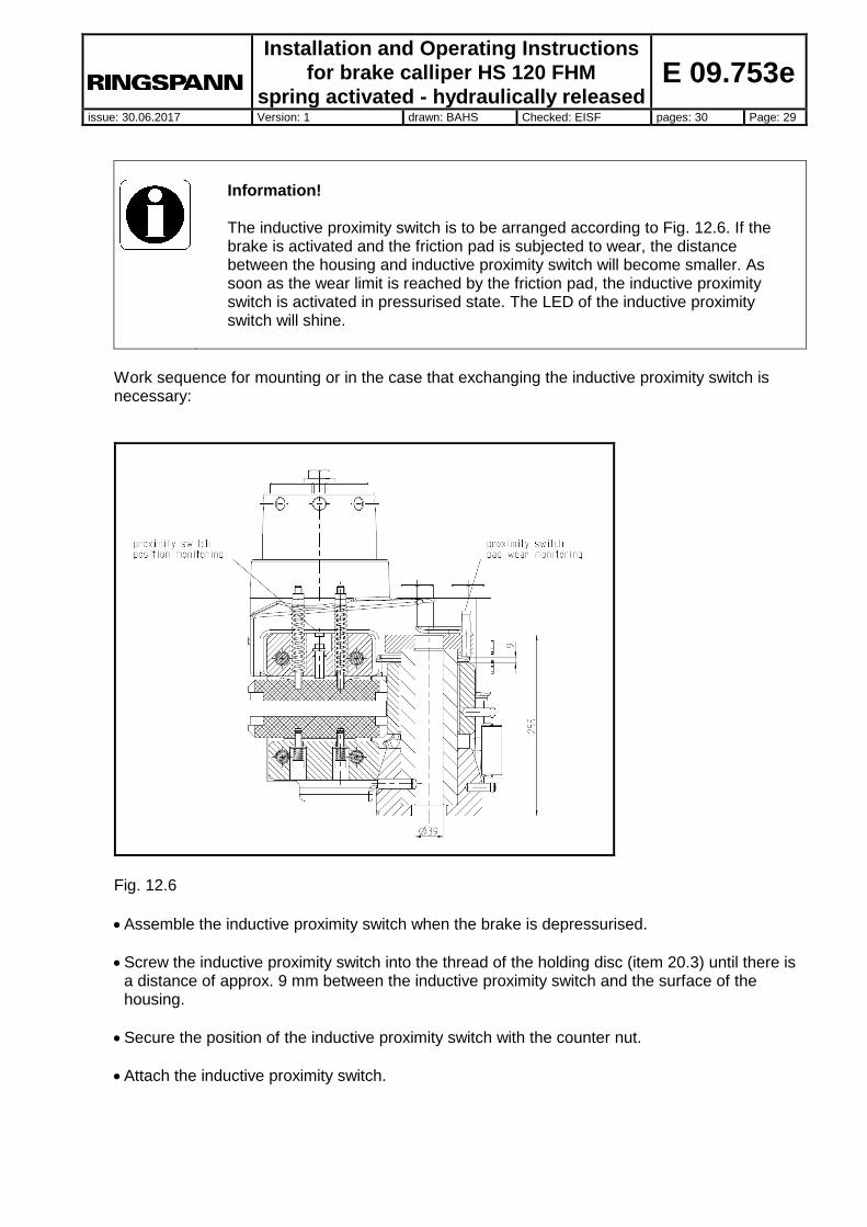
Information! The inductive proximity switch is to be arranged according to Fig. 12.6. If the brake is activated and the friction pad is subjected to wear, the distance between the housing and inductive proximity switch will become smaller. As soon as the wear limit is reached by the friction pad, the inductive proximity switch is activated in pressurised state. The LED of the inductive proximity switch will shine.
Work sequence for mounting or in the case that exchanging the inductive proximity switch is necessary:
Fig. 12.6
Assemble the inductive proximity switch when the brake is depressurised.
Screw the inductive proximity switch into the thread of the holding disc (item 20.3) until there is a distance of approx. 9 mm between the inductive proximity switch and the surface of the housing.
Secure the position of the inductive proximity switch with the counter nut.
Attach the inductive proximity switch.

Installation and Operating Instructions
for brake calliper HS 120 FHM
spring activated - hydraulically released
E 09.753e
issue: 30.06.2017 Version: 1 drawn: BAHS Checked: EISF pages: 30 Page: 30
Check the proper functioning of the inductive proximity switch by holding a metal object approx.
2 mm in front of the inductive proximity switch. The LED of the inductive proximity switch will shine.
Important!
Follow the exact work steps described, since otherwise the inductive proximity switch could get damaged.


![Weldable trolley rail clip Y7b - Bemo Rail · Weldable trolley rail clip Y7b A A SECTION A-A 4 Hexagon flange nut Grade 8 H.D.G. M16 ISO-metric - m = 0,044 [kg] 3 Hexagon head screw](https://img.dokumen.tips/doc/110x75/5ea77d341d0c0c3a3446a98b/weldable-trolley-rail-clip-y7b-bemo-rail-weldable-trolley-rail-clip-y7b-a-a-section.jpg)