Embed Size (px)
Citation preview

Testing and AdjustingD5B POWER SHIFT TRANSMISSION
Testing And Adjusting
Power Shift Transmission
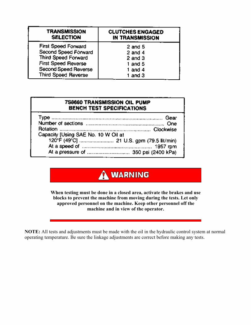
When testing must be done in a closed area, activate the brakes and useblocks to prevent the machine from moving during the tests. Let only
approved personnel on the machine. Keep other personnel off themachine and in view of the operator.

Hydraulic Controls (First Speed Reverse) 1. Oil filter. 2. Priority valve. 3. Spool. 4. Oil filter bypass valve. 5. Oil pump. 6.
Magnetic strainer. 7. Load piston. 8. Modulating relief valve. 9. Oil sump. 10. Check valve. 11. Pressure differential and
safety valve. 12. Orifice. 13. Oil cooler. 14. Temperature bypass valve. 15. Spool for speed selection. 16. Torque
converter. 17. Lubrication relief valve. 18. Spool for direction selection. 19. Body of the pressure control and selector
valve. 20. Relief valve for converter inlet. 21. Oil line for transmission lubrication. 22. Oil line for lubrication of the bevel
gear.
NOTE: All tests and adjustments must be made with the oil in the hydraulic control system at normaloperating temperature. Be sure the linkage adjustments are correct before making any tests.
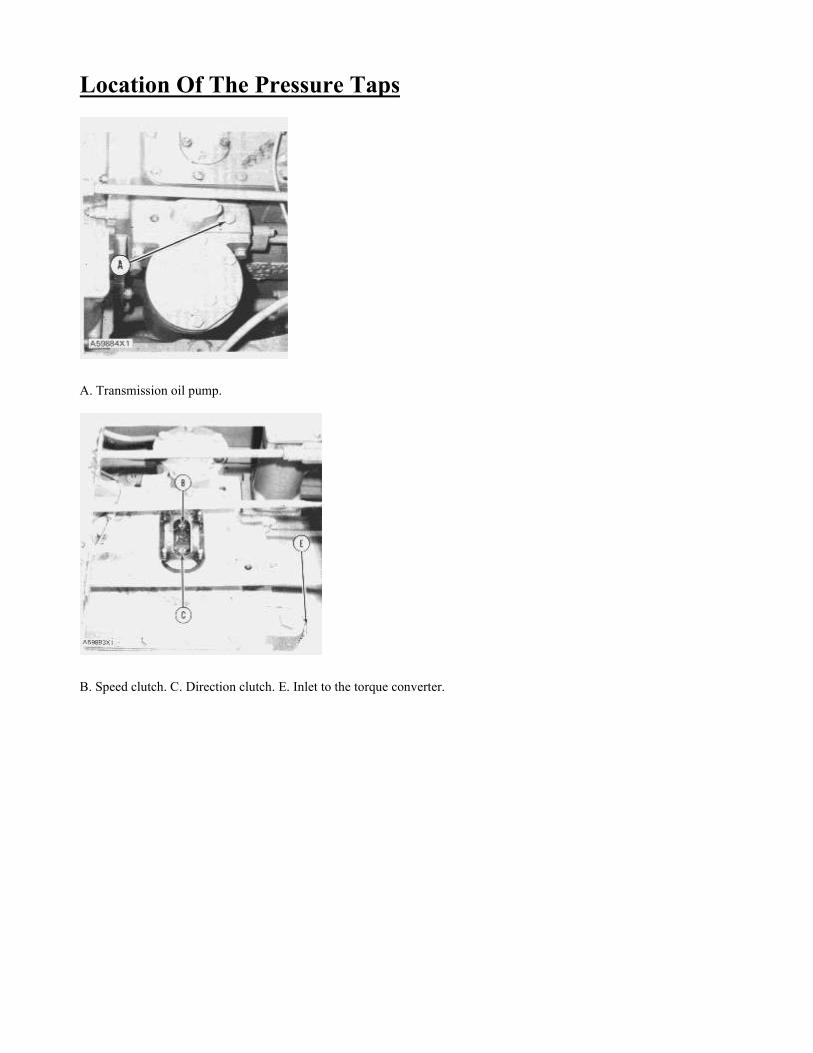
Location Of The Pressure Taps
A. Transmission oil pump.
B. Speed clutch. C. Direction clutch. E. Inlet to the torque converter.
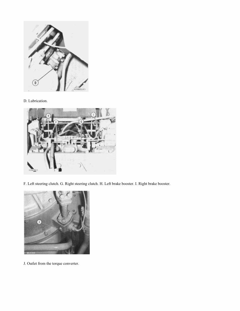
D. Lubrication.
F. Left steering clutch. G. Right steering clutch. H. Left brake booster. I. Right brake booster.
J. Outlet from the torque converter.


Pressure Control And Selector Valve 7. Load piston. 8. Modulating relief valve. 10. Check valve. 11. Differential valve.
15. Spool for speed selection. 18. Spool for direction selection. 19. Body for the pressure control and selector valve. 20.
Converter inlet relief valve. 23. Shims.
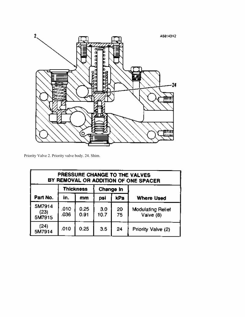
Priority Valve 2. Priority valve body. 24. Shim.
When testing must be done in a closed area, activate the brakes and useblocks to prevent the machine from moving during the tests. Let only
approved personnel on the machine. Keep other personnel off themachine and in view of the operator.
NOTE: All tests and adjustments must be made with the oil in the hydraulic control system at normaloperating temperature. Be sure the linkage adjustments are correct before making any tests.

Selector Valve And Control Linkage Adjustments
Linkage Adjustment (Inside) 1. Direction cam. 2. Direction cam detent. 3. Horizontal shaft (speed). 4. Spool for speed
selection. 5. Spool for direction. 6. Vertical shaft (direction). 7. Machined face of valve body. 8. Nuts.
Do not make any adjustments to selector valve or control linkage withengine running.
Adjustment of Selector Valve Spools
NOTE: Before adjustments are made, make sure nuts (8) are tightened to a torque of 25 ± 3 lb. ft. (35± 4 N·m).
1. Disconnect the control linkage levers from vertical shaft (6) and horizontal shaft (3).
2. Move shaft (6) so that detent (2) is in the REVERSE groove of direction cam (1).
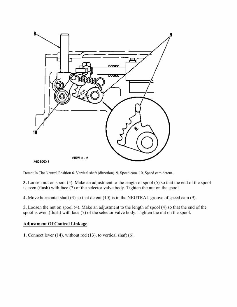
Detent In The Neutral Position 6. Vertical shaft (direction). 9. Speed cam. 10. Speed cam detent.
3. Loosen nut on spool (5). Make an adjustment to the length of spool (5) so that the end of the spoolis even (flush) with face (7) of the selector valve body. Tighten the nut on the spool.
4. Move horizontal shaft (3) so that detent (10) is in the NEUTRAL groove of speed cam (9).
5. Loosen the nut on spool (4). Make an adjustment to the length of spool (4) so that the end of thespool is even (flush) with face (7) of the selector valve body. Tighten the nut on the spool.
Adjustment Of Control Linkage
1. Connect lever (14), without rod (13), to vertical shaft (6).
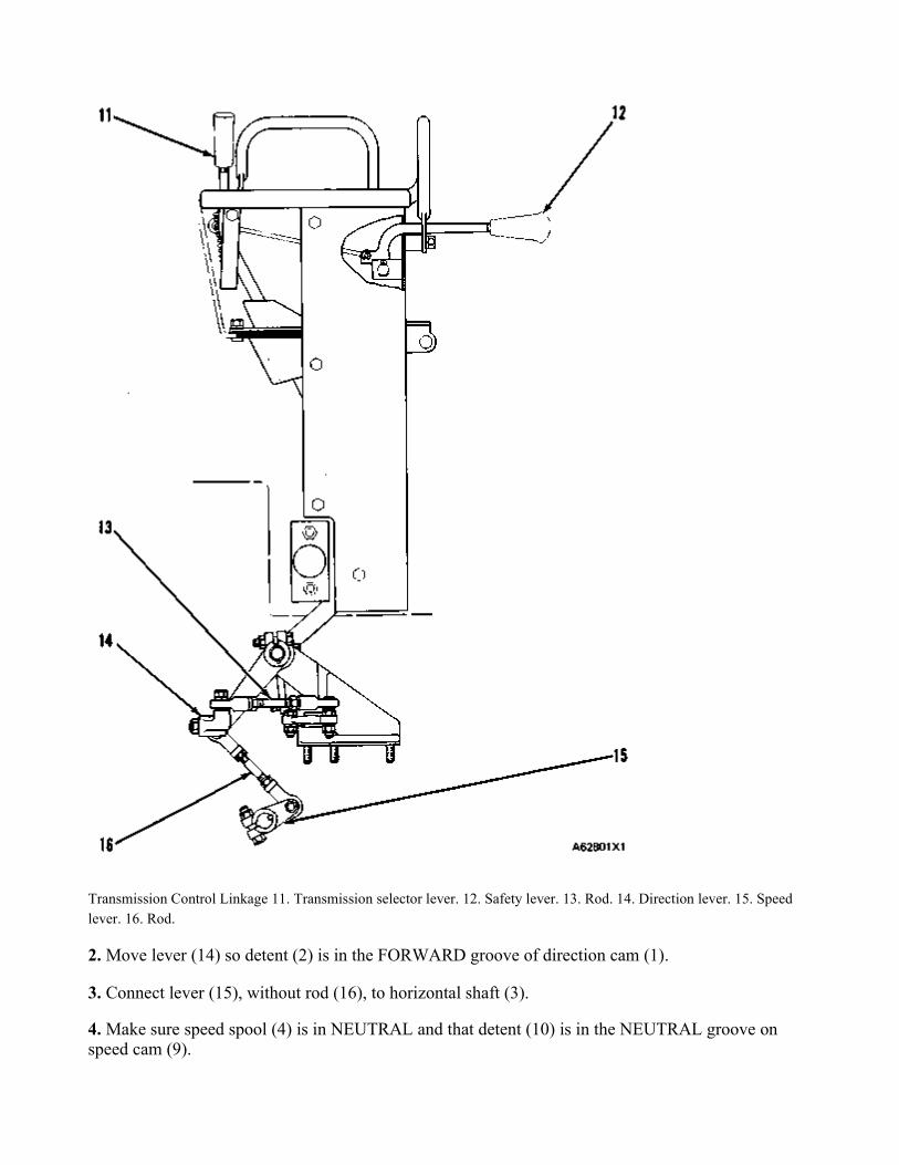
Transmission Control Linkage 11. Transmission selector lever. 12. Safety lever. 13. Rod. 14. Direction lever. 15. Speed
lever. 16. Rod.
2. Move lever (14) so detent (2) is in the FORWARD groove of direction cam (1).
3. Connect lever (15), without rod (16), to horizontal shaft (3).
4. Make sure speed spool (4) is in NEUTRAL and that detent (10) is in the NEUTRAL groove onspeed cam (9).

5. With rods (13) and (16) disconnected from levers (14) and (15), move transmission selector lever(11) to the FORWARD side of the NEUTRAL opening of shift guide (17), as shown.
Transmission Selector Lever On The Forward Side Of The Neutral Opening 11. Transmission selector lever. 17. Shift
guide.
6. Connect rod (13) to direction lever (14). Make adjustments, as necessary, to the length of rod (13)and tighten the nuts on each end of the rod to a torque of 9 ± 3 lb. ft. (12 ± 4 N·m).
7. Move transmission selector lever (11) to the center of the NEUTRAL opening of shift guide (17),as shown.
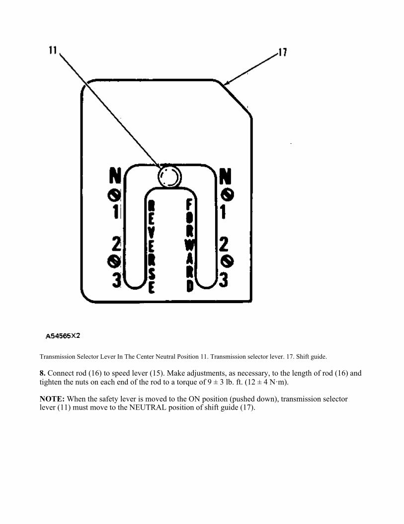
Transmission Selector Lever In The Center Neutral Position 11. Transmission selector lever. 17. Shift guide.
8. Connect rod (16) to speed lever (15). Make adjustments, as necessary, to the length of rod (16) andtighten the nuts on each end of the rod to a torque of 9 ± 3 lb. ft. (12 ± 4 N·m).
NOTE: When the safety lever is moved to the ON position (pushed down), transmission selectorlever (11) must move to the NEUTRAL position of shift guide (17).