Embed Size (px)
Citation preview

Electrical System
9.14.6 Transmission Shift Control Switch
a. Travel Select Lever
The transmission shift control switch (travel select lever) (1) is located on the left side of the steering column. The switch has three positions: (F) FORWARD (2) (all the way up), (N) NEUTRAL (3) (center), and (R) REVERSE (4) (all the way down). The switch or lever must be in the (N) NEUTRAL (3) position to permit engine starting.
Moving the lever (1) opens and closes electrical contacts in the switch, allowing electricity to flow to the appropriate relays and onto the transmission shift solenoids.
Travel selections are changed by grasping the lever, pulling it toward the steering wheel, then up or down to the desired selection, (F) FORWARD (2) or (R) REVERSE (4).
When the switch is shifted to the (R) REVERSE (4) position, the back-up alarm will automatically sound. (Refer to circuit diagrams in Section 9.8, “Transmission Gear Selection Troubleshooting,” and also, Section 9.14.7, a. “Travel Select Lever and Wiring Harness Testing.”)
Refer to Section 4.3.2, c. “Transmission Travel and Gear Select Lever Removal,” and Section 4.3.2, d. “Transmission Travel and Gear Select Lever Installation,” for removal and installation instructions.
b. Gear Select Lever
The gear select lever (5) is part of the transmission shift control switch (travel select lever). The lever has a twist-grip handle with four positions.
The vehicle has four forward gears and three reverse gears.
First gear is used for the highest torque and pulling power, and the higher-numbered gears are for increasing vehicle travel speed.
Refer to Section 4.3.2, c. “Transmission Travel and Gear Select Lever Removal,” and Section 4.3.2, d. “Transmission Travel and Gear Select Lever Installation,” for removal and installation instructions.
OH179021
2
3
4MA7710
5
9.2
28 Model 8042, 10042, 10054 Legacy Rev. 10/03
Electrical System
9.14.7 Transmission Solenoid Valves
The transmission is shifted via six solenoids. Three solenoid valves (Y1, Y2 and Y3) are contained in an UPPER spool-type solenoid cartridge assembly (valve body) (6).
The remaining three solenoid valves (Y4, Y5 and Y6) are contained in the LOWER spool-type solenoid cartridge assembly (valve body) (7). While each 12-volt solenoid coil at the transmission is the same, the internal wiring to the solenoids is different and connected so that the various transmission clutches can be actuated via input from the transmission shift control switch (travel select lever).
By placing the transmission shift control switch (travel select lever) in any given position, a combination of solenoids are activated, which, in turn, engage a combination of internal clutches. (Refer to Section 9.14.7, a. “Travel Select Lever and Wiring Harness Testing,” and Section 9.14.7, b. “Upper and Lower Transmission Valve Body Solenoid Testing.”)
If the transmission is not shifting properly, the transmission shift control switch (travel select lever), wiring harness or transmission shift solenoids should be checked in order to determine which component is defective. Specific information to determine which travel position and corresponding component is not responding can be found by referring to the circuit diagrams in Section 9.8, “Transmission Gear Selection Troubleshooting,”. Replace a defective component.
MA7720
6
7
Model 8042, 10042, 10054 Legacy Rev.
9.22910/03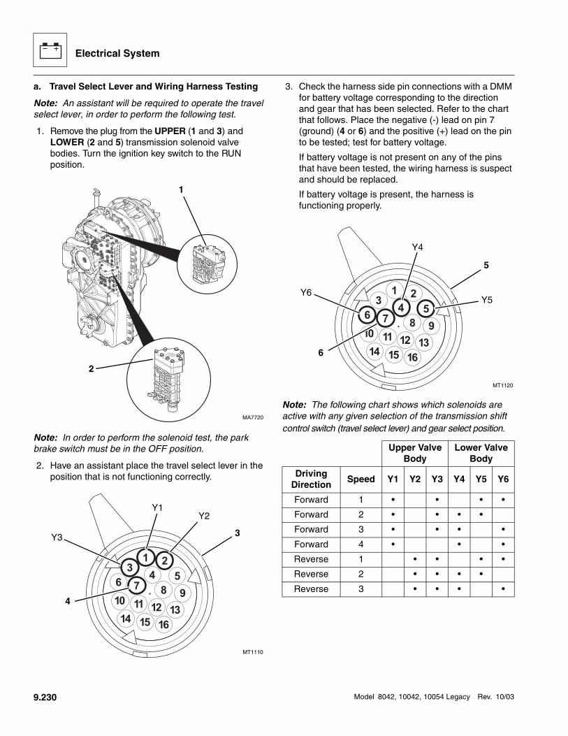
Electrical System
a. Travel Select Lever and Wiring Harness Testing
Note: An assistant will be required to operate the travel select lever, in order to perform the following test.
1. Remove the plug from the UPPER (1 and 3) and LOWER (2 and 5) transmission solenoid valve bodies. Turn the ignition key switch to the RUN position.
Note: In order to perform the solenoid test, the park brake switch must be in the OFF position.
2. Have an assistant place the travel select lever in the position that is not functioning correctly.
3. Check the harness side pin connections with a DMM for battery voltage corresponding to the direction and gear that has been selected. Refer to the chart that follows. Place the negative (-) lead on pin 7 (ground) (4 or 6) and the positive (+) lead on the pin to be tested; test for battery voltage.
If battery voltage is not present on any of the pins that have been tested, the wiring harness is suspect and should be replaced.
If battery voltage is present, the harness is functioning properly.
Note: The following chart shows which solenoids are active with any given selection of the transmission shift control switch (travel select lever) and gear select position.
MA7720
1
2
MT1110
Y1Y2
Y3 3
4
Upper Valve Body
Lower Valve Body
DrivingDirection
Speed Y1 Y2 Y3 Y4 Y5 Y6
Forward 1 • • • •
Forward 2 • • • •
Forward 3 • • • •
Forward 4 • • •
Reverse 1 • • • •
Reverse 2 • • • •
Reverse 3 • • • •
MT1120
Y4
Y5Y6
5
6
9.230
Model 8042, 10042, 10054 Legacy Rev. 10/03
Electrical System
b. Upper and Lower Transmission Valve Body Solenoid Testing
Inspect the solenoid connector plugs (7 and 12). Following the chart below, test each pin connection on the upper transmission valve body connector for continuity and shorting. Each solenoid should have between 25.0 and 30.0 ohms of resistance when testing with an ohm/volt meter. Replace a defective solenoid valve. (Refer to Section 9.14.7, c. “Transmission Upper Valve Body Solenoid Removal.”
Note: All six solenoids within both upper and lower solenoid valve body housings are of the same design.
c. Transmission Upper Valve Body Solenoid Removal
Note: Before removing the valve body protective cover, clean the area around the housing to prevent contamination.
1. If the vehicle has one battery, disconnect the negative (-) battery cable at the negative (-) battery terminal (17).
If the vehicle has dual batteries, disconnect both negative battery cables from both negative (-) battery terminals (18).
Solenoid Pin Position
ActiveSolenoid
Callout
1 Y1 8
2 Y2 9
3 Y3 10
7 Ground 11
4 Y4 13
5 Y5 14
6 Y6 15
7 Ground 16
MT1090
7
89
10
11
MT1100
12
1314
15
16
MH489017
18
Model 8042, 10042, 10054 Legacy Rev. 10/03
9.231
Electrical System
2. Remove the six capscrews (1) four hex-head capscrews (2), ten lockwashers (3 and 4) and protective cover plate (5) secured over the transmission solenoid cartridge valve (6). Inspect the protective cover gasket (7); replace if torn or missing.
3. Disconnect the internal wire connector (8) from the solenoid valve that is being removed. Label the internal wire connections if removing more than one solenoid valve.
4. Remove the solenoid capscrew (9), retaining plate (10) and flat washer (11) securing the solenoid valve (6) to the transmission.
5. Remove the solenoid valve (6) and replace.
d. Transmission Upper Valve Body Solenoid Installation
Note: When installing the solenoid valve into the valve body, position the solenoid valve wires so that they do not interfere with the protective cover plate.
1. Install the flat washer (11) and solenoid valve (6) along with the retaining plate (10). Connect the internal wire connector to solenoid. Insure that the claw side (12) of the retaining plate is facing down toward the valve body surface (13).
2. Install the solenoid capscrew (9) and torque to 53 lb-in (6 Nm).
3. Install the protective cover gasket (7) on the valve body. Position the protective cover plate (5) over the gasket. Install six lockwashers (3) and capscrews (1), and tighten until the valve body spring (14) (upper valve body only) is compressed and the cover plate sits flush over the gasket.
4. Install the four lockwashers (4) and four capscrews (2). Torque to 84 lb-in (9,5 Nm).
5. If the vehicle has one battery, connect the negative (-) battery cable to the negative (-) battery terminal (15).
If the vehicle has dual batteries, connect both negative battery cables to both negative (-) battery terminals (16).
6. Test the operation of the transmission. Put the transmission through its entire range of gears (speeds) in both (F) FORWARD and (R) REVERSE, and check that the transmission also shifts into (N) NEUTRAL.
7. Verify that each function works properly and that the transmission does not engage when in (N) NEUTRAL.
For further information, refer to the Transmission Service Manual, Model ZF 4 WG-98 TC P/N 8990455 (ZF P/N 5871 135 002).
e. Transmission Lower Valve Body Solenoid Removal
Note: In order to service the lower valve body housing, the upper valve body housing MUST be removed to allow access to the lower housing protective cover. The area around the upper and lower valve body housing must be thoroughly cleaned to avoid contamination of internal transmission components.
1. If the vehicle has one battery, disconnect the negative (-) battery cable at the negative (-) battery terminal (15).
If the vehicle has dual batteries, disconnect both negative battery cables from both negative (-) battery terminals (16).
MT2300
1
2
3
4
5
67
8
9
10
1112
13
14
MH489015
16
9.232
Mo del 8042, 10042, 100 54 Legacy Rev. 10/03
Electrical System
2. Thoroughly clean the area around the upper and lower valve body housing.
3. Remove screws securing the upper valve housing to the transmission.
4. Remove upper valve body housing from transmission, and set aside in a clean area, free of dirt, grease and oil.
5. Remove the upper valve housing flat gasket.
6. Remove the nine lower valve body protective cover screws (17), lockwashers (18) protective cover (19) and gasket (20)
7. Disconnect the internal wire connector (21) from the solenoid valve that is being removed. Label the internal wire connections if removing more than one solenoid valve.
8. Remove the solenoid capscrew (22) and retaining plate (23), securing the solenoid valve (24) to the transmission.
9. Remove the solenoid valve (24) and replace.
f. Transmission Lower Valve Body Solenoid Installation
Note: When installing the solenoid valve into the valve body, position the solenoid valve wires so they do not interfere with the protective cover plate.
1. Install the solenoid valve (24) and retaining plate (23). Connect the internal wire connector (21) to the solenoid. Insure that the claw side of the retaining plate (23) is facing down toward the valve body surface.
2. Install the solenoid capscrew (22) and torque to 53 lb-in (6 Nm).
3. Install the protective cover gasket (20 onto the valve body. Position the protective cover (19) over the gasket. Install lockwashers (18) and capscrews (17), and tighten until the cover plate is compressed and it sits flush over the gasket. Torque to 84 lb-in (9,5 Nm).
4. Install the upper transmission valve body gasket and upper valve body assembly to transmission.
5. Install the lockwashers and capscrews, and torque screws to 84 lb-in (9,5 Nm).
6. If the vehicle has one battery, connect the negative (-) battery cable to the negative (-) battery terminal (15).
If the vehicle has dual batteries, connect both negative battery cables to both negative (-) battery terminals (16).
7. Test the operation of the transmission. Put the transmission through its entire range of gears (speeds) in both (F) FORWARD and (R) REVERSE, and check that the transmission also shifts into (N) NEUTRAL.
8. Verify that each function works properly and that the transmission does not engage when in (N) NEUTRAL.
For further information, refer to the Transmission Service Manual, Model ZF 4 WG-98 TC, P/N 8990455 (ZF P/N 5871 135 002).
MT2480
17
18
19
20
21
22
2324
Model 8042, 10042, 10054 Legacy Rev. 10/03
9.233