Embed Size (px)
Citation preview

EPCOS Product Profile (India) 2013
Power Quality Solutions
Power Factor Correction
www.epcos.com

The Company: EPCOS India Pvt. Ltd.
EPCOS India Private Limited (EIPL) is a Member of TDK-EPC Corporation, Japan.EPCOS emerged in 1999 as a successor to the joint venture Siemens Matsushita Components and the former Siemens passive Components and Electron Tubes Group. The company has been selling electronic components in India since the early 60s. Today, all business activities in India come under the umbrella of EPCOS India Private Limited, having Registered head office at Kalyani Plant in West Bengal and regional offices in Mumbai, Delhi, Bengaluru and Kolkata. In mid-90s EPCOS significantly stepped up its commitment to India by opening new manufacturing facility at Kalyani in West Bengal and Nashik in Maharashtra. And now, EPCOS again reinforced its trust in India by opening up one more manufacturing facility at Bawal in Haryana.
EPCOS in India is involved in design, manufacturing and marketing of a broad range of top quality products such as AC-mfd capacitors, LV Power Factor Correction Capacitors (resin, inert gas and oil filled designs), Key Components required for PF correction system, PF correction systems (APFC Panels), MV Capacitors, MV Capacitor Switch, MV Reactive Power Compensation systems, Power Electronic Capacitors, DC Capacitors, MPP film and high performance ferrite cores. Nashik factory also houses the Global R&D for Film metallisation, AC and PFC Products and Systems while Kalyani is Centre of Excellence for soft ferrites. EPCOS India also services the demands of customers for a wide variety of components from global factories of TDK-EPC.
EPCOS India has a strong sales and marketing team spread over the country. Our strength in market is based on the technical competence and marketing experience of our sales force. It is backed up by a very efficient and dedicated Channel Partner network to cover entire India and some neighboring countries.
About TDK-EPC Corporation:TDK-EPC Corporation(TDK-EPC), a TDK group company, is a leading manufacturer of electronic components,modules and systems, headquartered in Tokyo, Japan. It was established on
stOctober 1 2009. TDK-EPC has emerged from combination of passive electronic components business of TDK and the EPCOS Group and markets its products under the product brands, TDK and EPCOS.
TDK Corporation is the sole shareholder of TDK-EPC Corporation.
EIPL 2013

Index
Page
Preview 4
11
Contents
Contacts 87
PFC capacitor series overview 6
PQS Key components overview 8
PFC capacitorsPhaseCap Premium PhaseCap Super Heavy Duty 16 PhiCap 21 SquareCap 27 LT-APP 35
PF controllers and measuring devicesBR6000 series 38BR5000 series 41BR4000 series 45 BR7000 series 48Grid analysis tool MC7000-3 52
Switching devicesCapacitor contactors 54 Thyristor modules for dynamic PFC (TSM-series) 57
ReactorsReactors - Antiresonance harmonic filter 61
Fundamentals of power factor correction 64Components of Power Factor Correction 65 Standard Values: Selection Tables for cables, cable cross sections and fuses 68Capacitor selection chart 70Individual PFC for motors 71Individual PFC for transformers 72Detuned PFC in general 73Detuned PFC important facts and instructions 74Capacitor voltage rating selection guideline 75 Dynamic PFC important facts and instructions 78
PFC basic formulae 79
Cautions 82
Other PFC products in the basket 86
Important notes 10
EIPL 2013

4 EIPL 2013
Power factor
results in
Higher energy consumption andcosts,Less power distributed via the network,Power loss in the network,Higher transformer losses,Increased voltage drop in power distribution networks.
Power factor improvement
Power factor improvement can beachieved by
Compensation of reactive power with capacitors,Active compensation – using semiconductors,Overexcited synchronous machine(motor /generator).
Types of PFC (detuned or conventional)
individual or fixed compensation(each reactive power producer isindividually compensated),group compensation (reactive powerproducers connected as a groupand compensated as a whole),central or automatic compen sation(by a PFC system at a central point),mixed compensation.
reactive power compensation systems(detuned /conventional) are installedfor larger loads like industrial machinery.Such systems consist of a groupof capacitor units that can be cut inand cut out and which are driven andswitched by a power factor controller.
Reactive Power [KVAr]2 2 2Q = S — P
Q Q2 C
Q1
S2
S1
Apparent Power [kVA]2 2 2S = P + Q
Active Power [kW]2 2 2P = S — Q
sin
With power factor correction the apparent powerS can be decreased by reducing the reactive
generated
Every electric load that works withmagnetic fields (motors, chokes,transformers, inductive heating, arcwelding, generators) produces a vary-ing degree of electrical lag, which iscalled inductance. This lag of inductiveloads maintains the current sense (e.g.positive) for a time even though thenegative-going voltage tries to reverseit. This phase shift between currentand voltage is maintained, current andvoltage having opposite signs. Duringthis time, negative power or energy is produced and fed back into the network. When current and voltagehave the same sign again, the sameamount of energy is again needed tobuild up the magnetic fields in induc-tive loads. This magnetic reversal
In AC networks (50 /60 Hz) such aprocess is repeated 50 or 60 times asecond. So an obvious solution is tobriefly store the magnetic reversal energy in capacitors and relieve thenetwork (supply line) of this reactiveenergy. For this reason, automatic
j1
P
j2
power Q.
**
Preview
General
The increasing demand of electricalpower and the awareness of the necessity of energy saving is very upto date these days. Also the aware-ness of power quality is increasing,and power factor correction (PFC) andharmonic filtering will be implementedon a growing scale. Enhancing powerquality – improvement of power factor– saves costs and ensures a fast return on investment. In power distrib-ution, in low- and medium-voltagenetworks, PFC focuses on the powerflow (cos Ø ) and the optimization ofvoltage stability by generating reactivepower – to im prove voltage quality andreliability at distribution level.
How reactive power is
energy is called reactive power.
U
I U
I
Linear loads:voltage was followed by current.
Non linear load produce non sinusoidal currents when connected to sinusoidal voltage.

5EIPL 2013
Uninterruptible Power supply
M
3~
EMC filterC
250/350/ 550 Hz
Overvoltageprotection
Tunedharmonicfilters
Linear loadwith fixedPFC
M3~
Overvoltageprotection
DynamicPFCsystems
Overvoltageprotection
Passiveharmonicfilters
(de-tuned PFCsystems)
Overvoltageprotection
Overvoltageprotection
Activeharmonicfilters
Power Factor Correction (PFC)and Harmonic Filtering
DC link(Aluminum electrolyticor film capacitors)
EMC filter
Frequency converter
C
Chargingresistor
Output filter
Preview
Power Quality Solution strategy
Along with the emerging demand forpower quality and a growing aware-ness of the need for environmentalprotection, the complexity in the ener-energy market is increasing: users and decision-makers are consequentlyfinding it increasingly difficult to locatethe best product on the market and tomake objective decisions. It is in mostcases not fruitful to compare catalogsand data sheets, as many of their parameters are identical in line withthe relevant standards. Thus operatingtimes are specified on the basis of
tests under laboratory conditions thatmay differ significantly from the realityin the field. In addition, load structureshave changed from being mainly linearin the past to non-linear today. All thisproduces a clear trend: the market is calling increasingly for customizedsolutions rather than off-the-shelfproducts. This is where Power QualitySolutions come into the picture. It offers all key components for an effective PFC system from a single source, together with:
Application know-howTechnical skillsExtensive experience in the field ofpower quality improvementA worldwide network of partnersContinuous developmentSharing of information
These are the cornerstones on whichPower Quality Solutions are built. Onthe basis of this strategy, EPCOS isnot only the leading manufacturer ofpower capacitors for PFC applicationsbut also a PQS supplier with a centuryof field experience, reputation and reliability.

6 EIPL 2013
PFC Capacitor series for power factor correction capacitors
PFC Capacitor Series Overview
*Other voltages on request.
PhaseCap Premium B25667L . . .
Power KVAr 5…31
Voltage range V 415...800 V*
Frequency Hz 50Hz
Impregnation Gas-impregnated, dry type, Non-PCB
Life expectancy Hrs Up to 130 000 h for -40/D
Up to 180 000 h for -40/C
Inrush current A 300 I• R
PhaseCap Super Heavy Duty B25673L . . .
Power KVAr 5…33
Voltage range V 415...1000 V*
Frequency Hz 50 Hz
Impregnation Non-PCB, semi-dry biodegradable resin
Life expectancy Hrs Up to 200 000 h for -40/C
Up to 150 000 h for -40/60
Inrush current 400 IR•
PhiCap ND B32343L . . . /B32344B . . .
Power KVAr 5…30
Voltage range V 230...525 V*
Frequency Hz 50 Hz
Impregnation
Life expectancy Hrs Up to 100 000 hours
Inrush current 200 IR•
PhiCap HD B32447A . . . /B32448A . . .
Power KVAr 1…30
Voltage range V 415...480 V*
Frequency Hz 50 Hz
Impregnation
Life expectancy Hrs Up to 115 000 hours
Inrush current 250 IR•
A
Non-PCB, semi-dry biodegradable resin
A
Non-PCB, semi-dry biodegradable resin
A

7EIPL 2013
PFC Capacitor Series Overview
*Other voltages on request.
PFC Capacitor series for power factor correction capacitors
SquareCap-ENDC B32457L . . .
Power KVAr 1…50.0
Voltage range V 415…440 V*
Frequency Hz 50 Hz
Impregnation
Life expectancy Hrs Up to 100 000 hours
Inrush current A 200 I• R
SquareCap-EHDLL B32459L . . .
Power KVAr 1…60.0
Voltage range V 415…525 V*
Frequency Hz 50 Hz
Impregnation
Life expectancy Hrs Up to 125 000 hours
Inrush current A 250 I• R
SquareCap-ESHDC B32455L . . .
Power KVAr 1…50.0
Voltage range V 415…525 V*
Frequency Hz 50 Hz
Impregnation
Life expectancy Hrs Up to 150 000 hours
Inrush current A 350 I• R
LT-APP B25160 . . .
Power KVAr 1…100
Voltage range V 415…525 V*
Frequency Hz 50 Hz/ 60Hz
Impregnation Non PCB, biodegradable oil
Life expectancy Hrs Up to 300 000 hours
Inrush current A (400 to 500) I• R
Non-PCB, semi-dry biodegradable resin
Non-PCB, semi-dry biodegradable resin
Non-PCB, semi-dry biodegradable resin

88 EIPL 2013
PQS Key Components Overview
PF controllers
BR Series and Ordering Details
Output stages Relay outputs Transistor outputs Interface Ordering code
BR6000-R06 6 - B44066R6006R230N 1
BR6000-R12 12 - B44066R6012R230N 1
BR6000-R12 12 - RS232 B44066R6312R230N 1
BR6000-R12 12 - RS485 B44066R6412R230N 1
BR6000-T06 - 6 B44066R6106R230N 1
BR6000-T12 - 12 B44066R6112R230N 1
BR5000-R08 8 - RS232 and RS485 B44066R5908A415N 1
BR5000-R16 16 - RS232 and RS485 B44066R5916A415N 1
BR5000-T16 - 16 RS232 and RS485 B44066R5716A415N 1
BR4904 4 - - B44066R4904A230N 1
BR4008 8 - - B44066R4808A230N 1
-
-
BR6000
BR6000-R06 BR6000-R12 BR6000-T06 BR6000-T12
Supply voltage 245 V AC ( 20%; L-N) 245 V AC ( 20%; L-N) 245 V AC ( 20%; L-N) 245V AC ( 20%; L-N)
Measurement 30-525 V AC (L-N) 30-525 V AC (L-N) 30-300 V AC (L-N) 30-300 V AC (L-N)
voltage range or (L-L) or (L-L) - -
Measurement X/5 or X1/A X/5 or X1/A X/5 or X1/A X/5 or X1/A
current selectable selectable selectable selectable
Frequency 50/60 Hz 50/60 Hz 50/60 Hz 50/60 Hz
BR5000
Supply voltage 415V AC 415V AC 415V AC
(-40% to +20%; L-L) (-40% to +20%; L-L) (-40% to +20%; L-L)
Measurement 3Ph 3wire 415V AC 3Ph 3wire 415V AC 3Ph 3wire 415V AC
voltage range (-40% to +20%) (-40% to +20%) (-40% to +20%)
Measurement current X/5 or X1/A selectable X/5 or X1/A selectable Only 5Amp CT secondary
Frequency 45Hz to 62.5Hz 45Hz to 62.5Hz 45 Hz to 55 Hz
BR5000-R08 BR5000-R16 BR5000-T16
BR4000
BR BR
Supply voltage 230V AC (-25% to +20%; L-N) 230V AC (-25% to +20%; L-N)
Measurement voltage range 230V AC (-25% to +20%; L-N) 230V AC (-25% to +20%; L-N)
Measurement current X/5 or X1/A externally selectable X/5 or X1/A externally selectable
Frequency 47Hz to 53 Hz 47Hz to 53 Hz
4904 4008
BR7000 15 relay outputs PF controller for
MC7000-3 Grid analysis tool for 3 phase measuring, display and storage B44066M1301E230of electric parameters
3 phase measuring and controlling B44066R7415E230

9EIPL 2013
Switching devices and detuned filters
PQS Key Components Overview
Parameter Capacitor contactors Thyristor modules Reactors - Antiresonance harmonic filter
With Pre-closing Thyristor switch for For detuning applicationresistor dynamic PFC systems with high linearity
x Voltage 230...690 V TSM-LC: 3 440 V 230...1000 Vx TSM-HV: 3 690 V
Output range 12.5...100 KVAr for B...J230 TSM-LC: 10...50 KVAr 5...100 KVAr7...60 KVAr for B...C240 TSM-HV: 50 KVAr
Frequency 50/60 Hz 50/60 Hz 50 or 60 Hz
Detuning Suitable for detuned Suitable for detuned Factor: 5.67%, 7%, 14%and conventional systems and conventional systems
Ordering code B44066S...J230 TSM-LC: B44066T...R440 B44066D...for all PFC systems TSM-HV: B44066T...R690B44066S...C240 for all PFC systems
EIPL 2013

Important Notes
The following applies to all products named in this publication:
1. Some parts of this publication contain s tatements aboutthe suitability of our products for certain areas of appli-cation. These statements are based on our knowledgeof typical requirements that are often placed on our prod-ucts in the areas of application concerned. We neverthe-less expressly point out that such statements cannot beregarded as binding statements about the suitabilityof our products for a particular customer application.As a rule, EPCOS is either unfamiliar with individual customer applications or less familiar with them than the customers themselves. For these reasons, it is always ultimately incumbent on the customer to check and decidewhether an EPCOS product with the properties describedin the product specification is suitable for use in a partic-ular customer application.
2. We also point out that in individual cases, a malfunc-tion of electronic components or failure before theend of their usual service life cannot be completelyruled out in the current state of the art, even if they areoperated as speci fied. In customer applications requiringa very high level of operational safety and especially in customer applications in which the malfunction or failureof an electronic component could endanger human life orhealth (e.g. in accident prevention or life-saving systems),it must therefore be ensured by means of suitable designof the customer application or other action taken by the customer (e.g. installation of protective circuitry or redundancy) that no injury or damage is sustained by thirdparties in the event of malfunction or failure of an electroniccomponent.
3. The warnings, cautions and product-specific notesmust be observed.
4. In or der to satisfy certain technical requirements, some ofthe products described in this publication may containsubstances subject to restrictions in certain jurisdictions(e.g. because they are classed as hazardous).Useful information on this will be found in our MaterialData Sheets on the Internet (www.epcos.com/material).Should you have any more detailed questions, please contact our sales offices.
5. We constantly strive to improve our products. Conse-quently, the products described in this publicationmay change from time to time. The same is true of thecorresponding product specifications. Please checktherefore to what extent product descriptions and speci-fications contained in this publication are still applicablebefore or when you place an order.
We also reserve the right to discontinue productionand delivery of products. Consequently, we cannotguarantee that all products named in this publication willalways be available.
The aforementioned does not apply in the case of individual agreements deviating from the foregoing forcustomer-specific products.
6. Unless otherwise agreed in individual contracts, all orders are subject to the current version of the “GeneralTerms of Delivery for Products and Services in the Electrical Industry” published by the GermanElectrical and Electronics Industry Association (ZVEI).
7. The trade names EPCOS, BAOKE, Alu-X, CeraDiode,CSMP, CSSP, CTVS, DeltaCap, DigiSiMic, DSSP, FormFit, MiniBlue, MiniCell, MKD,MKK,
PhaseCube, PhaseMod, SIKOREL, SilverCap, SIMDAD, SiMic,SIMID,SineFormer,
PhiCap, SIFERRIT, SIFI,
SIOV, SIP5D, SIP5K, ThermoFuse, WindCap are trademarks registered or pending in Europe and in other countries. Further information
will be found on the Internet at www.epcos.com/trademarks.
SquareCap,
AgriCap, PoleCap, MLSC, MotorCap, PCC, PhaseCap,
10 EIPL 2013

11EIPL 2013
PhaseCap Premium PFC CapacitorsGas-impregnated l Dry type l Concentric winding l Wavy cut l Triple safety system
Applications
Automatic PFC equipment, capacitor banksIndividual fixed PFC (e.g. motors,transformers, lighting)Group fixed PFCDetuned capacitor banksFilter applicationsDynamic PFC
Features
Compact design in cylindrical aluminum can with stud Concentric windingMKK-technology with wavy cut andheavy edgeVoltage range 230 V … 800 VOutput range 5.0 … 33 KVAr
Electrical
Long life expectancyHigh pulse current withstand capability
Mechanical and maintenance
Reduced mounting costs
Maintenance-freeHighest packing density thanks tocompact dimensions
Safety
Self-healingOverpressure disconnectorShock hazard protected terminalsLongterm approvedCeramic discharge resistor pre-mounted
Environmental
Dry design, inert gasNo oil leakage
General
PhaseCap capacitors in cylindricalaluminum cases have been de-signed for power factor correctionin low-voltage applications.
Loads like motors and transform-ers consume active power as wellas reactive power.
Generators, supply cables andother electrical distribution equip-ment, in turn, should be relieved ofreactive power.
The MKK (metalized plastic compact) AC series is intended to increase packing density per bankand cut component costs.
Improved thermal response andsimplified installation are advan-tages of the cylindrical aluminumcase.
PoleCap Capacitors:A modified version of PhaseCap capacitor with connection cable, suitable for long-term out door applications and for mounting on the pole.
Mounting position upright/ horizontal

12 EIPL 2013
PhaseCap Premium PFC Capacitors
Series Type
Power-KVAr 5….31KVAr
Rated voltage-V (AC) 415...800 V* Frequency 50 Hz
Transient peak current 300 I R•maximum permissible
Maximum permissible -40/Dtemperature category
Losses 0.5W/KVAr(without discharge resistors)
Maximum V +10%(up to 8 h daily)/ V +15% (up to 30 min daily)** R R
+Permissible voltage V +20%(up to 5 min daily)/ V 30% (up to 1 min daily)** R R
Maximum Up to 1.6 I *** • R
Permissible current
Safety Self-healing, overpressure disconnector
Impregnation Gas-impregnated, dry type, Non-PCB
Up to 130 000 h for -40/DLife expectancy
Up to 180 000 h for -40/C
Cooling Natural or forced
Case shape/finish Extruded round aluminium can with stud
Terminal Optimized capacitor safety terminals Mounting and grounding Threaded stud at bottom of can (max. torque for M12=10Nm)
Enclosure IP 20, indoor mounting (optionally with terminal cap for IP54)
Discharge resistor Provided with discharge resistor
Connection Delta
Casing of capacitor cell Extruded round aluminium can with stud
Dielectric Polypropylene film (metallised)
No. of switching per annum Max. 7500 switching
Reference standard IEC60831–1/2, UL 810-5th edition
B25667L
≤
Technical data : PhaseCap Premium PFC Capacitors
* Other voltages available on request** V rated voltage R
*** I : RMS line current that occurs at rated sinusoidal voltage and rated frequency, excluding transients.R
Note: for capacitors with different features/parameters than above, please check with our nearest sales office
Gas-impregnated l Dry type l Concentric winding l Wavy cut l Triple safety system

PhaseCap Premium PFC Capacitors - 3 Phase
PhaseCap Premium PFC Capacitors
Rating Voltage Material code I C d x h Packing MOQ ApproxR N
KVAr V (AC) A mF mm units weight Kg
PhaseCap - 415 V(AC) 3PH, 50Hz (Series B25667)
5 415 B25667L4926A375 7.0 3 x 30.8 116 x 164 1 4 1.1
6.3 415 B25667L4117A375 8.8 3 x 38.5 x 164 1 1.2
10 415 B25667L4197A375 13.9 3 x 64.1 x 164 1 1.2
12.5 415 B25667L4237A375 17.4 3 x 77 x 164 1 1.3
15 415 B25667L4277A375 20.9 3 x 92.5 x 164 1 1.4
16.7 415 B25667L4307A375 23.2 3 x 102.9 x 164 1 1.5
20 415 B25667L4387A375 27.8 3 x 128.2 x 200 1 1.7
25 415 B25667L4467A375 34.8 3 x 154.1 136 x 200 1 2.1
PhaseCap - 440 V(AC) 3PH, 50Hz (Series B25667)
5 440 B25667L4826A375 6.6 3 x 27.4 x 164 1 4 1.2
7.5 440 B25667L4127A375 9.8 3 x 41.1 x 164 1 4 1.2
10.4 440 B25667L4177A375 13.7 3 x 57 x 164 1 4 1.3
12.5 440 B25667L4207A375 16.4 3 x 68.5 x 164 1 1.4
14.2 440 B25667L4237A365 18.6 3 x 77.9 x 164 1 1.4
15 440 B25667L4247A375 19.7 3 x 82.2 x 164 1 1.5
20 440 B25667L4347A375 26.2 3 x 114.1 136 x 200 1 2.0
25 440 B25667L4417A375 32.8 3 x 137.1 136 x 200 1 2.1
PhaseCap - 480 V(AC) 3PH, 50Hz (Series B25667)
5 480 B25667L4696A375 6.0 3 x 23 x 164 1 1.2
6.25 480 B25667L4866A375 7.5 3 x 28.3 x 164 1 1.2
7.5 480 B25667L4107A375 9.0 3 x 34.6 x 164 1 1.3
8 480 B25667L4117A365 9.6 3 x 38.4 x 164 1 1.3
10 480 B25667L4147A375 12.0 3 x 47.9 x 164 1 1.4
12.5 480 B25667L4177A365 15.0 3 x 57.6 x 164 1 1.5
15 480 B25667L4207A365 18.0 3 x 69.1 x 200 1 1.5
16.7 480 B25667L4237A355 20.1 3 x 76.9 x 200 1 1.8
20 480 B25667L4287A375 24.1 3 x 95.8 x 200 1 2.2
25 480 B25667L4347A365 30.1 3 x 115.2 x 200 1 2.5
31 480 B25667L4427A375 37.3 3 x 143 x 200 1 3.0
PhaseCap - 525 V(AC) 3PH, 50Hz (Series B25667)
6.25 525 B25667L5726A375 7.0 3 x 24.1 x 164 1 1.1
8 525 B25667L5966A375 8.8 3 x 32.1 x 164 1 1.1
10 525 B25667L5127A375 11.0 3 x 40.1 x 164 1 1.2
12.5 525 B25667L5147A375 13.8 3 x 48.1 x 164 1 1.3
15 525 B25667L5177A375 16.5 3 x 57.1 x 200 1 1.8
16.7 525 B25667L5197A375 18.4 3 x 64.3 x 200 1 1.8
20 525 B25667L5247A375 22.0 3 x 80.1 136 x 200 1 2.2
25 525 B25667L5287A375 27.5 3 x 96.3 136 x 200 1 2.5
30 525 B25667L5347A375 33.0 3 x 115.5 136 x 200 1 2.8
116 4
116 4
116 4
116 4
116 4
116 4
4
116
116
116
116 4
116 4
116 4
4
4
116 4
116 4
116 4
116 4
116 4
116 4
116 4
116 4
136 4
136 4
136 4
116 4
116 4
116 4
116 4
116 4
116 4
4
4
4
13EIPL 2013
Gas-impregnated l Dry type l Concentric winding l Wavy cut l Triple safety system

14 EIPL 2013
Rating Voltage Material code I C d x h Packing MOQ Approx.R N
KVAr V (AC) A mF mm units weight Kg
PhaseCap - 690 V(AC) 3PH, 50Hz (Series B25667)
5 690 B25667C6336A375 4.2 3 x 11 116 x 164 6 6 1.3
10 690 B25667C6676A375 8.4 3 x 23 x 164 6 6 1.4
12.5 690 B25667C6836A375 10.5 3 x 28 x 164 6 6 1.5
15 690 B25667C6107A375 12.6 3 x 34 x 164 6 6 1.5
20.8 690 B25667C6137A375 17.5 3 x 47 136 x 200 4 4 2.0
25 690 B25667C6167A375 21 3 x 56 136 x 200 4 4 2.2
PhaseCap - 800 V(AC) 3PH, 50Hz (Series B25667)
5 800 B25667C7246A375 3.6 3 x 8 x 164 6 6 1.2
7.5 800 B25667C7376A375 5.4 3 x 12.4 x 164 6 6 1.2
10 800 B25667C7496A375 7.2 3 x 17 x 164 6 6 1.3
12.5 800 B25667C7626A375 9 3 x 21 x 164 6 6 1.4
15 800 B25667C7746A375 11 3 x 25 x 164 6 6 1.5
20 800 B25667C7996A375 14.5 3 x 33 136 x 200 4 4 2.0
25 800 B25667C7127A375 18 3 x 41 136 x 200 4 4 2.3
28 800 B25667C7137A375 20 3 x 46 136 x 200 4 4 2.4
116
116
116
116
116
116
116
116
PhaseCap Premium PFC Capacitors
Other voltages available on request.
Packing units for capacitors equal minimum order quantity.
Orders will be rounded up to packing unit or multiple thereof.
PhaseCap Premium PFC Capacitors - 3 Phase
Gas-impregnated l Dry type l Concentric winding l Wavy cut l Triple safety system

15EIPL 2013
Capacitor up to 690 V AC Capacitor > 690 V AC
Discharge resistor
Pre-mounted for series B25667, B25673available as spare parts upon request
PhaseCap Premium PFC Capacitors
Discharge resistor module
Side mounted dischargeresistor module for B25673, and B25669 series
B25667
Dimensional drawings
Gas-impregnated l Dry type l Concentric winding l Wavy cut l Triple safety system

16 EIPL 2013
PhaseCap Super Heavy Duty PFC Capacitors
Applications
Automatic PFC equipment, capacitor banksIndividual fixed PFC (e.g. motors,transformers, lighting)Group fixed PFCDetuned capacitor banksFilter applicationsDynamic PFC
Features
Compact design in cylindrical aluminum can with stud Concentric winding MKK-technology with wavy cut andheavy edge Voltage range: 230 … 1000 VOutput range: 5.0 … 33.0 KVAr
Electrical features
Very high life expectancy High inrush current capability (up to 400 ) High overcurrent capability (up to 2.0
Mechanical and maintenance
Reduced mounting costs Maintenance-free Compact dimensions Mounting position upright
Safety
Self healing Overpressure disconnector Shock hazard protected terminals Pre-mounted ceramic dischargeresistor
General
The new PhaseCap Super Heavy Duty (SHD)PFC capacitor is based on the EPCOS MKK technology known for many years from the successful PhaseCap series with
its unique concentric windings. Based on years of experience in PFC and millions of sold
capacitors, EPCOS presents the next step in PFC capacitor
evolution.Using polypropylene as dielectric
and semi-dry biodegradable resin
as impregnation agent, the PhaseCap Super Heavy Duty (SHD)
offers higher inrush currentlcapability (up to 400 I ) and overR
lcurrent capability (up to 2 I )R
even compared to PhaseCap. Withan output of up to 33 KVAr at verysmall height it meets the dimensional
requirements of panel builders. Its new enhanced terminals permit the connection of a broader variety
of cables and cable sizes. Depending on the operating conditions PhaseCap Compact provides a life expectancy of
up to 200 000 hours, more than any other capacitor in the EPCOS PFC
capacitor portfolio besides MKV.
Semi-dry biodegradable resin l Wavy cut lDual safety systeml
Concentric winding

17EIPL 2013
Series type
Power-KVAr 5….33KVAr
Rated voltage-V (AC) 415...1000 V* Frequency 50 Hz
lTransient peak current 400 I R
maximum permissible
o oMaximum permissible -40 C to 60 Ctemperature category
Losses 0.45W/KVAr(without discharge resistors)
Maximum VR +10%(up to 8 h daily)/ VR +15% (up to 30 min daily)** +permissible voltage V +20%(up to 5 min daily)/ V 30% (up to 1 min daily)** R R
Maximum Up to 1.6 IR*** permissible current
Safety Self-healing, overpressure disconnector
Impregnation Non-PCB, semi-dry biodegradable resin
Life expectancy Up to 200 000 h for -40/CUp to 150 000 h for -40/60
Cooling Natural or forced
Case shape/finish Extruded round aluminium can with stud
Terminal Optimized capacitor safety terminals Mounting and grounding Threaded stud at bottom of can (max. torque for M12=Nm)
Enclosure IP 20, indoor mounting (optionally with terminal cap for IP54)
Discharge resistor Provided with discharge resistor
Connection Delta
Casing of capacitor cell Extruded round aluminium can with stud
Dielectric Polypropylene film (metallised)
No. of switching per annum Max. 10 000 switching
Reference standard IEC60831–1/2, UL 810-5th edition
B25673L
≤
l
Technical data : PhaseCap Super Heavy Duty PFC Capacitors
PhaseCap Super Heavy Duty PFC Capacitors
* Other voltages available on request** V rated voltage R
*** I : RMS line current that occurs at rated sinusoidal voltage and rated frequency, excluding transients.R
Note : for capacitors with different features/parameters than above, please check with our nearest sales office
Semi-dry biodegradable resin l Wavy cut lDual safety systeml
Concentric winding

18 EIPL 2013
PhaseCap Super Heavy Duty PFC Capacitors - 3 Phase
Rating Voltage Material code I C d x h Packing MOQ Approx.R N
KVAr V (AC) A mF mm units weight Kg
PhaseCap Super Heavy Duty - 415 V(AC) 3PH, 50Hz (Series B25673)
5 415 B25673L4052A 10 7 3 x 30.8 85 x 125 1 1 0.7
6.2 415 B25673L4062A 10 8.6 3 x 38.2 x 162 1 1 1.0
7.5 415 B25673L4072A510 10.4 3 x 46.2 x 162 1 1 1.0
10.4 415 B25673L4102A 10 14.5 3 x 64.1 100 x 162 1 1 1.4
12.5 415 B25673L4122A510 17.4 3 x 77 x 200 1 1 1.7
15 415 B25673L4152A 10 20.9 3 x 92.5 x 200 1 1 1.7
20.8 415 B25673L4202A810 28.9 3 x 128.2 116 x 200 1 1 2.2
25 415 B25673L4252A 11 35 3 x 154 x 200 1 1 3.2
PhaseCap Super Heavy Duty - 440 V(AC) 3PH, 50Hz (Series B25673)
5 440 B25673L4052A 40 6.6 3 x 27.4 x 125 1 1 0.8
7.5 440 B25673L4072A540 9.8 3 x 41.1 x 162 1 1 1.0
10.4 440 B25673L4102A 40 13.6 3 x 57 x 162 1 1 1.4
12.5 440 B25673L4122A540 16.4 3 x 68.5 x 162 1 1 1.4
15 440 B25673L4152A 40 19.7 3 x 82.2 x 200 1 1 1.7
20 440 B25673L4202A 40 26.3 3 x 109.7 x 200 1 1 2.2
25 440 B25673L4252A 40 32.8 3 x 137.1 x 200 1 1 2.2
30 440 B25673L4302A 41 39.2 3 x 164 x 200 1 1 3.2
33 440 B25673L4332A 41 43.3 3 x 181 x 200 1 1 3.2
PhaseCap Super Heavy Duty - 480 V(AC) 3PH, 50Hz (Series B25673)
5.5 480 B25673L4052A580 6.6 3 x 25.3 x 125 1 1 0.7
6.3 480 B25673L4062A380 7.6 3 x 29 x 162 1 1 1.0
8.3 480 B25673L4082A380 10 3 x 38.2 x 162 1 1 1.0
11 480 B25673L4112A 80 13.2 3 x 50.7 x 162 1 1 1.7
13.8 480 B25673L4132A880 16.6 3 x 63.6 x 200 1 1 1.7
16.7 480 B25673L4162A780 20.1 3 x 76.9 x 200 1 1 1.7
22 480 B25673L4222A 80 26.5 3 x 101.4 x 200 1 1 2.2
28 480 B25673L4282A 81 33.4 3 x 128 x 200 1 1 3.2
PhaseCap Super Heavy Duty - 525 V(AC) 3PH, 50Hz (Series B25673)
6.6 525 B25673L5062A620 7.3 3 x 25.4 x 162 1 1 1.0
10 525 B25673L5102A 20 11 3 x 38.5 x 162 1 1 1.7
13.2 525 B25673L5132A220 14.5 3 x 50.8 x 200 1 1 1.7
16.7 525 B25673L5162A720 18.4 3 x 64.3 x 200 1 1 2.2
20 525 B25673L5202A 20 22 3 x 77 x 200 1 1 2.2
26.5 525 B25673L4262A581 29.2 3 x 102.1 136 x 200 1 1 3.2
85
85
100
100
136
85
85
100
100
100
116
116
136
136
85
85
85
100
100
100
116
136
85
100
100
116
116
PhaseCap Super Heavy Duty PFC CapacitorsSemi-dry biodegradable resin l Wavy cut lDual safety systeml
Concentric winding

19EIPL 2013
PhaseCap Super Heavy Duty PFC Capacitors
Rating Voltage Material code I C d x h Packing MOQ Approx.R N
KVAr V (AC) A mF mm units weight Kg
PhaseCap Super Heavy Duty - 690 V(AC) 3PH, 50Hz (Series B25673)
5 690 B25673L6052A 90 4.2 3 x 11.2 116 x 164 1 1 2.1
7.5 690 B25673L6072A590 6.3 3 x 16.7 116 x 164 1 1 2.1
10 690 B25673L6102A 90 8.4 3 x 22.5 116 x 164 1 1 2.1
12.5 690 B25673L6122A590 10.5 3 x 27.9 116 x 164 1 1 2.1
15 690 B25673L6152A 90 12.6 3 x 33.5 116 x 164 1 1 2.2
20.8 690 B25673L6202A890 17.4 3 x 46.5 136 x 200 1 1 3.2
25 690 B25673L6252A 90 20.9 3 x 55.7 136 x 200 1 1 3.2
PhaseCap Super Heavy Duty - 800 V(AC) 3PH, 50Hz (Series B25673)
5 800 B25673L8052A000 3.6 3 x 8.3 116 x 164 1 1 2.1
7.5 800 B25673L8072A500 5.4 3 x 12.4 116 x 164 1 1 2.1
10.0 800 B25673L8102A000 7.2 3 x 16.6 116 x 164 1 1 2.1
12.5 800 B25673L8122A500 9 3 x 20.7 116 x 164 1 1 2.1
15 800 B25673L8152A000 10.8 3 x 24.9 116 x 164 1 1 2.1
20 800 B25673L8202A000 15 3 x 33.2 136 x 200 1 1 3.2
25 800 B25673L8252A000 18 3 x 41.4 136 x 200 1 1 3.2
28 800 B25673L8252A000 20.2 3 x 46.4 136 x 200 1 1 3.2
PhaseCap Super Heavy Duty - 900 V(AC) 3PH, 50Hz (Series B25673)
10.4 900 B25673L9102A400 6.7 3 x 13.6 116 x 164 1 1 2.0
12.5 900 B25673L9122A500 8 3 x 16.4 116 x 164 1 1 2.0
15 900 B25673L9152A000 9.6 3 x 19.7 116 x 200 1 1 2.4
20 900 B25673L9202A000 12.8 3 x 26.2 136 x 200 1 1 3.1
25 900 B25673L9252A000 16 3 x 32.7 136 x 200 1 1 3.1
PhaseCap Super Heavy Duty - 1000 V(AC) 3PH, 50Hz (Series B25673)
10.4 1000 B25673L0102A400 6 3 x 11.0 116 x 164 1 1 2.0
12.5 1000 B25673L0122A500 7.2 3 x 13.3 116 x 164 1 1 2.0
15 1000 B25673L0152A000 8.7 3 x 15.9 116 x 200 1 1 2.4
20 1000 B25673L0202A000 11.6 3 x 21.2 136 x 200 1 1 3.1
25 1000 B25673L0252A000 14.4 3 x 26.5 136 x 200 1 1 3.1
PhaseCap Super Heavy Duty PFC Capacitors - 3 Phase
Semi-dry biodegradable resin l Wavy cut lDual safety systeml
Concentric winding

20 EIPL 2013
PhaseCap Super Heavy Duty PFC Capacitors
Dimensional drawings
Terminal type A, current up to 50 A type B, current up to 80 A Terminal 2 Terminal cross section 16 mm (without cable end lug) e r m i n a l c r o s s section 25 mm T
2 (without cable end lug)
/ Star washer / Star washer
Semi-dry biodegradable resin l Wavy cut lDual safety systeml
Concentric winding

21EIPL 2013
PhiCap PFC Capacitors
Applications
Power Factor Correction (PFC),automatic capacitor banksFixed PFC applications, e.g. motorcompensationDetuned PFC systemsDynamic PFC systems
Features
Compact design in cylindrical aluminum can with studStacked windingMKP technologyVoltage range 230 … 525 VOutput range 0.5 … 30 KVAr
Electrical
Up to 30 KVAr per case for three-phase applicationsUp to 6 KVAr per case for single-phase applicationsLong life expectancy of up to115 000 hours High pulse current withstand I capability (up to 200· )R
Mechanical and maintenance
Reduced mounting costs, easy installation and connection
Low weight and compact volumeMaintenance-free
Safety
Self-healingOverpressure disconnector
General
PhiCap capacitors are a tried andtested series of MKP (metalizedpolypropylene) capacitors from EPCOS which have been used for PFC applications for more than15 years.
The power range varies from 0.5 to30.0 kvar and 0.7 to 6.0 kvar persingle capacitor can, depending on a three-phase or single-phasecapacitor design.
The PhiCap capacitor is especiallyintended for power factor correc-tion in industrial applications.
The capacitors are manufacturedusing metalized polypropylene filmas the dielectric and housed in acylindrical aluminum case.
Available in two designs Normal Duty (ND) for linear inductive loads. Heavy Duty (HD) for loads having some amount of non-linearity (with detuning r eactor) .
Mounting position upright
Semi-dry biodegradable resin lStacked winding lDual safety system

22 EIPL 2013
PhiCap PFC Capacitors
Series type B32344B (metal top- 6 KVAr and onwards) B32448 series (3 KVAr and onwards)
Power-KVAr 0.5 to 30 KVAr 1.0....30 KVAr
Rated voltage-V (AC) 230...525 V* 415...480 V* Frequency 50 Hz 50 Hz
Transient peak current 200 250 maximum permissible
Maximum permissible -10/D -10/Dtemperature category
0.5 W/KVArLosses (without 0.5 W/KVAr
discharge resistor)
**Maximum V + 10%(up to 8 h daily)/V +15% (up to 30 min daily) V +10%(up to 8 h daily)/ VR +15% (up to 30 min daily)**RR R
permissible voltage ** V +20%(up to 5 min daily)/ VR+30% (up to 1 min daily)**RV + 20%(up to 5 min daily)/V +30% (up to 1 min daily)R R
Maximum 1.3 to 1.5 *** 1.5 to 1.8 *** permissible current
Safety Self-healing, overpressure disconnector Self-healing, overpressure disconnector
Impregnation Non-PCB, semi-dry biodegradable resin Non-PCB,
Life expectancy Up to 100 000 hours Up to 115 000 hours
Cooling Natural or forced Natural or forced
Case shape/finish Extruded round aluminium can with stud Extruded round aluminium can with stud
Terminal 6.3 mm fast-on terminals for 6.3 mm fast-on terminals for plastic top -1 to 5 KVAr plastic top - 1 and 2 KVAr
Screw terminal for metal top Optimized capacitor safety terminals 6 KVAr and above 3 KVAr onwards
Mounting and grounding Threaded stud at bottom of can (max. Threaded stud at bottom of can (max.
torque 4 Nm for M8 and 10Nm for M12) torque 4 Nm for M8 and 10Nm for M12)
Enclosure IP 00, indoor mounting (optionally with IP 00, indoor mounting (optionally with terminal cap for IP54) terminal cap for IP54)
Discharge resistor Provided with discharge resistor
Connection Delta Delta
Casing of capacitor cell Extruded round aluminium can with stud Extruded round aluminium can with stud
Dielectric Polypropylene film (metallised) Polypropylene film (metallised)
No. of switching Max. 5000 switching Max. 6000 switchingper annum
Reference standard IS : 13340/41(ISI mark applicable IS : 13340/41(ISI mark applicable for 415 and 440V) for 415 and 440V)
B32343L (plastic top up to 5 KVAr) B32447 series (1and 2 KVAr)
l lI IRR
llI IR R
semi-dry biodegradable resin
Provided with discharge resistor
≤ ≤
* Other voltages available on request ** V rated voltage R
*** I : RMS line current that occurs at rated sinusoidal voltage and rated frequency, excluding transients.R
Note : for capacitors with different features/parameters than above, please check with our nearest sales office
Technical data : PhiCap PFC Capacitors
PhiCap-ND PhiCap-HD
Semi-dry biodegradable resin lStacked winding lDual safety system

23EIPL 2013
PhiCap Normal Duty (ND) Capacitors - 3 Phase
Rating Voltage Material code I C d x h Packing MOQ Approx.R N
KVAr V (AC) A mF mm units weight Kg
PhiCap Normal Duty - 415 V(AC) 3PH, 50Hz (Series B32343 and B32344)
0.5 415 B32343L4002A510 0.7 3 x 3 53 x 117 12 12 0.3
1 415 B32343L4012A 10 1.4 3 x 6.5 53 x 117 12 12 0.3
1.5 415 B32343L4012A510 2.0 3 x 9.5 53 x 117 12 12 0.3
2 415 B32343L4022A 10 2.7 3 x 12.5 53 x 117 12 12 0.4
2.5 415 B32343L4022A510 3.4 3 x 15.5 63.5 x 129 12 12 0.4
3 415 B32343L4032A 10 4.1 3 x 18.5 63.5 x 129 12 12 0.4
4 415 B32343L4042A 10 5.5 3 x 25 63.5 x 152 12 12 0.4
5 415 B32343L4052A 10 6.9 3 x 31 63.5 x 152 12 12 0.5
6.3 415 B32344B4071A510 8.8 3 x 39 75 x 195 1 6 0.6
7.5 415 B32344B4072A510 10.4 3 x 46.5 75 x 195 1 6 0.7
8.3 415 B32344B4082A310 11.5 3 x 51.5 75 x 195 1 6 0.7
9 415 B32344B4092A 10 12.5 3 x 55.5 75 x 195 1 6 0.7
10 415 B32344B4102A 10 13.9 3 x 62 85 x 195 1 4 0.7
12.5 415 B32344B4122A510 17.3 3 x 77 85 x 270 1 4 1.0
15 415 B32344B4152A 10 20.8 3 x 92.5 85 x 270 1 4 1.8
20 415 B32344B4202A 10 27.8 3 x 123.5 85 x 345 1 4 1.8
25 415 B32344B4252A 10 34.7 3 x 154 85 x 345 1 4 2.0
PhiCap Normal Duty - 440 V(AC) 3PH, 50Hz (Series B32343 & B32344)
1 440 B32343L4012A 40 1.3 3 x 5.5 53 x 117 12 12 0.3
1.5 440 B32343L4012A540 1.9 3 x 8.5 53 x 117 12 12 0.3
2 440 B32343L4021A540 2.8 3 x 11.5 53 x 117 12 12 0.4
2.5 440 B32343L4022A540 3.2 3 x 14 63.5 x 129 12 12 0.4
3 440 B32343L4032A 40 3.9 3 x 16.5 63.5 x 129 12 12 0.5
4.2 440 B32343L4051A 40 5.5 3 x 23 63.5 x 129 12 12 0.5
5 440 B32343L4052A 40 6.5 3 x 27.5 63.5 x 152 12 12 0.6
5.6 440 B32343L4052A640 7.3 3 x 31 63.5 x 188 12 12 0.6
6 440 B32344B4071A540 7.8 3 x 33 75 x 195 1 6 0.6
7 440 B32344B4072A 40 9.2 3 x 38.5 75 x 195 1 6 0.6
7.5 440 B32344B4072A540 9.8 3 x 41 75 x 195 1 6 0.6
8.3 440 B32344B4101A 40 10.8 3 x 45.5 75 x 195 1 6 0.6
9 440 B32344B4092A 40 11.8 3 x 49.5 75 x 195 1 6 0.6
10 440 B32344B4102A 40 13.1 3 x 55 85 x 195 1 4 0.6
11.2 440 B32344B4112A240 14.6 3 x 61.4 85 x 195 1 4 0.8
12.5 440 B32344B4151A 40 16.4 3 x 68.5 85 x 270 1 4 0.8
14 440 B32344B4142A 40 18.3 3 x 76.4 85 x 270 1 4 1.0
15 440 B32344B4152A 40 19.6 3 x 82.5 85 x 270 1 4 1.2
16.7 440 B32344B4201A 40 21.9 3 x 91.5 85 x 345 1 4 1.2
19 440 B32344B4192A 40 24.9 3 x 104.5 85 x 345 1 4 1.2
20 440 B32344B4202A 40 26.2 3 x 110 85 x 345 1 4 1.2
20.8 440 B32344B4251A 40 27.3 3 x 114 85 x 345 1 4 1.2
25 440 B32344B4252A 40 32.8 3 x 137.5 90 x 345 1 4 1.5
28 440 B32344B4282A 40 36.7 3 x 153.5 90 x 345 1 4 1.6
30 440 B32344B4302A 40 39.4 3 x 164.5 90 x 345 1 4 1.8
PhiCap PFC CapacitorsSemi-dry biodegradable resin lStacked winding lDual safety system

24 EIPL 2013
Rating Voltage Material code I C d x h Packing MOQ Approx.R N
KVAr V (AC) A mF mm units weight Kg
PhiCap Normal Duty - 480 V(AC) 3PH, 50Hz (Series B32344)
5 480 B32344B4052A 80 6.0 3 x 23 75 x 195 1 6 0.6
8.3 480 B32344B4082A380 10 3 x 28.2 75 x 270 1 6 0.6
10.4 480 B32344B4121A580 12.5 3 x 48 85 x 270 1 4 0.8
11.1 480 B32344B4112A180 13.4 3 x 51.1 75 x 270 1 6 0.9
12.5 480 B32344B4151A 80 15.0 3 x 58 85 x 345 1 4 0.9
13.8 480 B32344B4132A880 16.6 3 x 63.6 85 x 270 1 4 1.0
15 480 B32344B4152A 80 18.0 3 x 69 85 x 345 1 4 1.5
16.6 480 B32344B4162A680 20 3 x 76.5 85 x 345 1 4 1.5
20.8 480 B32344B4251A 80 25.0 3 x 96 85 x 345 1 4 1.5
22.1 480 B32344B4222A180 26.6 3 x 101.8 90 x 345 1 4 1.8
25 480 B32344B4252A 80 30.0 3 x 115 90 x 345 1 4 1.8
27.7 480 B32344B4272A780 33.3 3 x 127.6 90 x 345 1 4 1.8
30 480 B32344B4302A 80 36.0 3 x 138 90 x 345 1 4 1.9
PhiCap Normal Duty - 525 V(AC) 3PH, 50Hz (Series B32344)
5 525 B32344B5052A 20 5.5 3 x 19 75 x 195 1 6 0.4
6.3 525 B32344B5071A520 6.9 3 x 24 75 x 195 1 6 0.5
8.3 525 B32344B5082A320 9.1 3 x 32 85 x 270 1 4 0.6
9.9 525 B32344B5092A920 10.9 3 x 38.1 75 x 270 1 6 0.6
10.4 525 B32344B5102A420 11.4 3 x 40 85 x 270 1 4 0.8
12.5 525 B32344B5151A 20 13.7 3 x 48 85 x 270 1 4 1.2
13.2 525 B32344B5132A220 14.5 3 x 50.8 85 x 270 1 4 1.3
16.7 525 B32344B5162A720 18.3 3 x 64 85 x 345 1 4 1.3
20.8 525 B32344B5202A820 22.8 3 x 80 90 x 345 1 4 1.5
26.5 525 B32344B5262A520 29.5 3 x 102.1 116 x 325 1 2 1.8
33.1 525 B32344B5332A120 36.4 3 x 127.5 116 x 325 1 2 2.0
PhiCap PFC Capacitors
Other voltages available on request.Packing units for capacitors equal minimum order quantity. Orders will be rounded up to packing unit or multiple thereof.
PhiCap Normal Duty (ND) Capacitors - 3 Phase
Semi-dry biodegradable resin lStacked winding lDual safety system

25EIPL 2013
PhiCap Heavy Duty (HD) Capacitors - 3 Phase
Rating Voltage Material code I C d x h Packing MOQ Approx.R N
KVAr V (AC) A mF mm units weight Kg
PhiCap Heavy Duty - 415 V(AC) 3PH, 50Hz (Series B32447 & B32448)
1 415 B32447A4012B 10 1.39 3 x 6.5 53 x 129 12 12 0.4
2 415 B32448A4022B 10 2.78 3 x 12.5 78.4 x 195 1 6 0.8
3 415 B32448A4032B 10 4.17 3 x 19 78.4 x 195 1 6 1.0
4 415 B32448A4042B 10 5.56 3 x 25 78.4 x 195 1 6 1.1
5 415 B32448A4052B 10 6.96 3 x 31 88.4 x 195 1 4 1.3
8 415 B32448A4082B 10 11.13 3 x 49.5 88.4 x 270 1 4 1.8
9 415 B32448A4092B 10 12.52 3 x 55.5 88.4 x 270 1 4 1.9
10 415 B32448A4102B 10 13.91 3 x 62 88.4 x 345 1 4 2.1
12.5 415 B32448A4122B510 17.39 3 x 77 88.4 x 345 1 4 2.3
PhiCap Heavy Duty - 440 V(AC) 3PH, 50Hz (Series B32447 & B32448)
1 440 B32447A4012B 40 1.3 3 x 5.5 53 x 117 12 12 0.5
2 440 B32447A4022B 40 2.62 3 x 12.5 63.5 x129 12 12 0.8
3 440 B32448A4032B 40 3.94 3 x 16.5 75 x 195 1 6 1.1
4 440 B32448A4042B 40 5.25 3 x 22 75 x 195 1 6 1.1
5 440 B32448A4052B 40 6.56 3 x 27.5 75 x 195 1 6 1.2
6 440 B32448A4062B 40 7.8 3 x 33 85 x 195 1 4 1.3
7.5 440 B32448A4072B540 9.84 3 x 41.5 85 x 270 1 4 1.7
8 440 B32448A4082B 40 10.5 3 x 44 85 x 270 1 4 1.8
9 440 B32448A4092B 40 11.8 3 x 49.5 85 x 270 1 4 1.8
10 440 B32448A4102B 40 13.12 3 x 55 85 x 270 1 4 1.9
12.5 440 B32448A4122B540 16.4 3 x 68.5 95 x 270 1 4 2.0
15 440 B32448A4152B 40 19.68 3 x 82.5 100 x 280 1 4 2.5
20 440 B32448A4202B840 26.24 3 x 109.6 116 x 280 1 2 2.9
25 440 B32448A4252B 40 32.8 3 x 137 116 x 325 1 2 3.8
30 440 B32448A4302B 40 39.4 3 x 164.5 136 x 325 1 2 5.0
PhiCap Heavy Duty - 480 V(AC) 3PH, 50Hz (Series B32448)
5 480 B32448A4052B 80 6.01 3 x 23 75 x 195 1 6 1.2
5.5 480 B32448A4052A580 6.6 3 x 25.3 75 x 195 1 6 1.2
8.3 480 B32448A4082A380 10 3 x 38.2 85 x 270 1 4 1.5
10 480 B32448A4102B 80 12.03 3 x 46 85 x 270 1 4 1.8
11.1 480 B32448A4112A180 13.4 3 x 51.1 85 x 270 1 4 1.9
12.5 480 B32448A4122B580 15.04 3 x 58 85 x 270 1 4 2.0
13.8 480 B32448A4132A880 16.6 3 x 63.6 90 x 270 1 4 2.0
14.5 480 B32448A4142B580 17.44 3 x 67 90 x 270 1 4 2.0
16.6 480 B32448A4162A680 20 3 x 76.5 85 x 345 1 4 2.3
20 480 B32448A4202B880 24.06 3 x 95.8 116 x 280 1 2 2.8
22.1 480 B32448A4222A180 26.6 3 x 101.8 116 x 280 1 2 2.8
25 480 B32448A4252B 80 30.07 3 x 115.1 116 x 325 1 2 3.1
27.7 480 B32448A4272A780 33.3 3 x 127.6 116 x 325 1 2 3.7
30 480 B32448A4302B 80 36.09 3 x 138.1 116 x 325 1 2 4.6
PhiCap PFC Capacitors
Other voltages available on request.* Packing units for capacitors equal minimum order quantity. Orders will be rounded up to packing unit or multiple thereof.
Semi-dry biodegradable resin lStacked winding lDual safety system

Semi-dry biodegradable resin lStacked winding lDual safety system

27EIPL 2013
SquareCap PFC Capacitors
General
The SquareCap box type capacitor is self standing in nature and is having modular construction (above 6KVAr) in a sheet metal enclosure.
It is a very popular capacitor design in India for many decades.
The SquareCap series is especially intended for use in industrial applications and locations such as commercial complexes, malls etc.The internal construction comprises of single phase basic capacitors cells connected to form delta construction externally within the enclosure. The terminal arrangement is of stud type.
SquareCap series is available in three designs:
ENDC: EPCOS Normal Duty Capacitor for normal inductive loads.
EHDLL: EPCOS Heavy Duty Long life Capacitor for loads exhibiting some amount of non-linearity.(Preferably withdetuning reactor).
ESHDC: EPCOS Super Heavy Duty Capacitor for non linear arduous and fluctuating loads and systems containing higher degree of harmonics.(Preferably with detuning reactor).
Applications Features
Electrical
Mechanical and maintenance
Safety
Self-healingOverpressure disconnectorSheet metal enclosure
Stand alone capacitors(Fixed Compensation)Capacitor banks Detuned capacitor banksDynamic PFC
Box Type self standing DesignVoltage Range:415V ….525VRange: 1kVAr to 60kVArResin ImpregnatedAvailable in three designs Viz. ENDC, EHDLL and ESHDC
High pulse current withstand capabilityVery high life expectancy
Reduced mounting costsMaintenance-free
Semi-dry biodegradable resin l l Modular construction Triple safety system

28 EIPL 2013
SquareCap PFC Capacitors
Technical data : SquareCap PFC Capacitors
Series type
Power-KVAr 1…50 KVAr 1…50 KVAr 1…50 KVAr
Rated voltage-V (AC) 415…440 V* 415…525 V* 415…525 V*
Frequency 50 Hz 50 Hz 50 Hz
Transient peak current upto 200 upto 250 upto 350 maximum permissible
Maximum permissible -10/D -10/D -10/D temperature category
Losses ≤ 0.5 W/KVAr ≤ 0.5 W/KVAr ≤ 0.5 W/KVAr(without discharge resistors)
Maximum permissible voltage V +10%(up to 8 h daily)/ V +10%(up to 8 h daily)/ V +10%(up to 8 h daily)/R R R
V +15% (up to 30 min daily) V +15% (up to 30 min daily) V +15% (up to 30 min daily)R R R
V +20%(up to 5 min daily)/ V +20%(up to 5 min daily)/ V +20%(up to 5 min daily)/R R R
V +30% (up to 1 min daily) V +30% (up to 1 min daily) V +30% (up to 1 min daily)R R R
Maximum 1.3 *** 1.5 *** 1.6 *** permissible current
Safety Self-healing, Self-healing, Self-healing, overpressure disconnector overpressure disconnector overpressure disconnector
Impregnation Non PCB, Non PCB, Non PCB, semi-dry biodegradable resin semi-dry biodegradable resin semi-dry biodegradable resin
Life expectancy Up to 100 000 hours Up to 125 000 hours Up to 150 000 hours
Cooling Natural or forced Natural or forced Natural or forced
Case shape/finish Rectangular/powder coated Rectangular/powder coated Rectangular/powder coatedSiemens grey colour Siemens grey colour Siemens grey colour
Terminal Threaded stud terminals Threaded stud terminals Threaded stud terminals with ceramic bushing with ceramic bushing with ceramic bushing
Mounting and Self standing with mounting Self standing with mounting Self standing with mounting grounding plates and screws for plates and screws for plates and screws for
grounding grounding grounding
Enclosure IP 20 IP 20 IP 20
Discharge resistor PCB mounted -included PCB mounted -Included PCB mounted -included
Connection Delta Delta Delta
Casing of capacitor cell Extruded aluminium can Extruded aluminium can Extruded aluminium can(hermetically sealed) (hermetically sealed) (hermetically sealed)
Dielectric Polypropylene film Polypropylene film Polypropylene film (metallised) (metallised) (metallised)
No. of switching Max. 5000 switching Max. 6000 switching Max. 7500 switching per annum
Reference standard IS: 13340/41 IS: 13340/41 IS: 13340/41(ISI mark applicable for (ISI mark applicable for (ISI mark applicable for 415 and 440V) 415 and 440V) 415 and 440V)
B32457L B32459L B32455L
l l lIR IR IR
** ** **
** ** **
l l lIR IR IR
SquareCap-ENDC SquareCap-EHDLL SquareCap-ESHDC
* other voltages available on request** V rated voltage R
*** I : RMS line current that occurs at rated sinusoidal voltage and rated frequency, excluding transients.R
Note : for capacitors with different features/parameters than above, please check with our nearest sales office
Semi-dry biodegradable resin l l Modular construction Triple safety system

29EIPL 2013
SquareCap ENDC Capacitors - 3 Phase
Rating Voltage Material code I C H x W x D Packing MOQ Approx.) R N
KVAr V (AC) A mF mm units weight Kg
SquareCap ENDC - 415 V(AC) 3PH, 50Hz (Series B32457)
1 415 B32457P4001A 11 1.3 3 x 6.3 95 x 125 x 45 1 25 0.8
2 415 B32457P4002A 11 2.7 3 x 12.5 120 x 125 x 45 1 25 0.8
3 415 B32457P4003A 11 4.1 3 x 19 120 x 145 x 55 1 25 1.4
4 415 B32457P4004A 11 5.5 3 x 25 140 x 145 x 55 1 25 1.5
5 415 B32457L4005A 11 6.9 3 x 31 215 x 185 x 60 1 1 1.6
6 415 B32457L4006A 11 8.3 3 x 37.5 300 x 240 x 80 1 1 2.4
7 415 B32457L4007A 11 9.7 3 x 44 300 x 240 x 80 1 1 2.6
7.5 415 B32457L4007A511 10.4 3 x 46.5 300 x 240 x 80 1 1 2.7
8 415 B32457L4008A 11 11.1 3 x 49.5 300 x 240 x 80 1 1 2.8
9 415 B32457L4009A 11 12.5 3 x 56 300 x 240 x 80 1 1 3.0
10 415 B32457L4010A 11 13.9 3 x 62 300 x 240 x 80 1 1 3.1
12.5 415 B32457L4012A511 17.3 3 x 77 300 x 240 x 80 1 1 3.6
15 415 B32457L4015A 11 20.8 3 x 92.5 300 x 240 x 80 1 1 3.8
20 415 B32457L4020A 11 27.8 6 x 62 300 x 240 x 160 1 1 6.5
25 415 B32457L4025A 11 34.7 6 x 77 300 x 240 x 160 1 1 7.2
30 415 B32457L4030A 11 41.7 6 x 92.5 300 x 240 x 160 1 1 7.9
50 415 B32457L4050A 11 69.5 12 x 77 350 x 240 x 320 1 1 12.5
SquareCap ENDC - 440 V(AC) 3PH, 50Hz (Series B32457)
1 440 B32457P5001A 11 1.3 3 x 5.5 95 x 125 x 45 1 25 0.8
2 440 B32457P5002A 11 2.6 3 x 11 120 x 125 x 45 1 25 0.8
3 440 B32457P5003A 11 3.9 3 x 16.5 120 x 145 x 55 1 25 1.4
4 440 B32457P5004A 11 5.2 3 x 22 140 x 145 x 55 1 25 1.5
5 440 B32457L5005A 11 6.6 3 x 27.5 215 x 185 x 60 1 1 1.6
6 440 B32457L5006A 11 7.9 3 x 33 300 x 240 x 80 1 1 2.2
7 440 B32457L5007A 11 9.2 3 x 38.5 300 x 240 x 80 1 1 2.4
7.5 440 B32457L5007A511 9.84 3 x 41.5 300 x 240 x 80 1 1 2.5
8 440 B32457L5008A 11 10.5 3 x 44 300 x 240 x 80 1 1 2.6
9 440 B32457L5009A 11 11.8 3 x 49.5 300 x 240 x 80 1 1 2.8
10 440 B32457L5010A 11 13.1 3 x 55 300 x 240 x 80 1 1 3.0
12 440 B32457L5012A 11 15.7 3 x 66 300 x 240 x 80 1 1 3.2
12.5 440 B32457L5012A511 16.4 3 x 69 300 x 240 x 80 1 1 3.3
15 440 B32457L5015A 11 19.6 3 x 82.5 300 x 240 x 80 1 1 3.8
20 440 B32457L5020A 11 26.2 6 x 55 300 x 240 x 160 1 1 6.1
25 440 B32457L5025A 11 32.8 6 x 69 300 x 240 x 160 1 1 7.0
35 440 B32457L5035A 11 45.9 12 x 48 350 x 240 x 320 1 1 8.0
40 440 B32457L5040A 11 52.5 12 x 54.8 350 x 240 x 320 1 1 8.8
50 440 B32457L5050A 11 65.6 12 x 69 350 x 240 x 320 1 1 12.4
(Basic cells x mF)
SquareCap PFC CapacitorsSemi-dry biodegradable resin l l Modular construction Triple safety system

30 EIPL 2013
SquareCap EHDLL Capacitors - 3 Phase
Rating Voltage Material code I C H x W x D Packing MOQ Approx.R N
KVAr V (AC) A mF mm units weight Kg
SquareCap EHDLL - 415 V(AC) 3PH, 50Hz (Series B32459)
1 415 B32459L4001A 11 1.3 3 x 6.3 170 x 125 x 45 1 20 1.0
2 415 B32459L4002A 11 2.7 3 x 12.5 170 x 125 x 45 1 20 1.1
3 415 B32459L4003A 11 4.1 3 x 19 215 x 185 x 60 1 20 1.5
4 415 B32459L4004A 11 5.5 3 x 25 215 x 185 x 60 1 20 1.6
5 415 B32459L4005A 11 7.0 3 x 31 215 x 185 x 60 1 1 1.8
7 415 B32459L4007A 11 10.4 3 x 46.5 300 x 240 x 80 1 1 3.2
7.5 415 B32459L4007A511 10.4 3 x 49.5 300 x 240 x 80 1 1 3.3
10 415 B32459L4010A 11 13.9 3 x 62 300 x 240 x 80 1 1 3.4
12.5 415 B32459L4012A511 17.3 3 x 77 300 x 240 x 80 1 1 3.5
15 415 B32459L4015A 11 20.8 3 x 92 300 x 240 x 80 1 1 4.0
20 415 B32459L4020A 11 27.8 6 x 62 300 x 240 x 160 1 1 6.1
25 415 B32459L4025A 11 34.7 6 x 77 300 x 240 x 160 1 1 6.5
30 415 B32459L4030A 11 41.7 6 x 92.4 300 x 240 x 160 1 1 7.5
40 415 B32459L4040A 11 55.6 12 x 61.6 350 x 240 x 320 1 1 11.0
50 415 B32459L4050A 11 69.5 12 x 77 350 x 240 x 320 1 1 11.8
SquareCap EHDLL - 440 V(AC) 3PH, 50Hz (Series B32459)
1 440 B32459L5001A 11 1.3 3 x 5.5 170 x 125 x 45 1 20 0.9
2 440 B32459L5002A 11 2.6 3 x 11 170 x 125 x 45 1 20 0.9
3 440 B32459L5003A 11 3.9 3 x 16.5 215 x 185 x 60 1 20 1.5
4 440 B32459L5004A 11 5.2 3 x 22 215 x 185 x 60 1 20 1.5
1 5 440 B32459L5005A 11 6.5 3 x 27.5 215 x 185 x 60 1 1.6
1 6 440 B32459L5006A 11 7.9 3 x 33 300 x 240 x 80 1 2.7
1 7 440 B32459L5007A 11 9.2 3 x 38.5 300 x 240 x 80 1 3.0
1 7.5 440 B32459L5007A511 9.8 3 x 41.5 300 x 240 x 80 1 3.0
1 8 440 B32459L5008A 11 10.5 3 x 44 300 x 240 x 80 1 3.2
1 9 440 B32459L5009A 11 11.8 3 x 50 300 x 240 x 80 1 3.3
110 440 B32459L5010A 11 13.1 3 x 55 300 x 240 x 80 1 3.3
112 440 B32459L5012A 11 15.8 3 x 67.5 300 x 240 x 80 1 3.4
112.5 440 B32459L5012A511 16.4 3 x 69 300 x 240 x 80 1 3.4
115 440 B32459L5015A 11 19.6 3 x 82.5 300 x 240 x 80 1 3.5
120 440 B32459L5020A 11 26.2 6 x 55 300 x 240 x 160 1 6.1
125 440 B32459L5025A 11 32.8 6 x 69 300 x 240 x 160 1 6.3
30 440 B32459L5030A 11 39.4 6 x 82.2 300 x 240 x 160 1 1 6.5
40 440 B32459L5040A 11 52.5 12 x 54.8 350 x 240 x 320 1 1 11.0
50 440 B32459L5050A 11 65.6 12 x 69 350 x 240 x 320 1 1 12.1
60 440 B32459L5060A 11 78.7 12 x 82.2 350 x 240 x 320 1 1 12.1
(Basic cells x mF)
SquareCap PFC CapacitorsSemi-dry biodegradable resin l l Modular construction Triple safety system

31EIPL 2013
Rating Voltage Material code I C H x W x D Packing MOQ Approx.R N
KVAr V (AC) A mF mm units weight
SquareCap EHDLL - 480 V(AC) 3PH, 50Hz (Series B32459)
5 480 B32459L8005A 61 6.0 3 x 23 215 x 185 x 60 1 1 1.8
5.5 480 B32459L8005A561 6.6 3 x 25.3 215 x 185 x 60 1 1 2.3
6 480 B32459L8006A 61 7.2 3 x 28 300 x 240 x 80 1 1 2.6
7.5 480 B32459L8007A561 9.0 3 x 34.5 300 x 240 x 80 1 1 2.8
8.3 480 B32459L8008A361 10 3 x 38.2 300 x 240 x 80 1 1 2.9
9 480 B32459L8009A 61 10.8 3 x 41.5 300 x 240 x 80 1 1 3.0
10 480 B32459L8010A 61 12.0 3 x 46.5 300 x 240 x 80 1 1 3.1
11.1 480 B32459L8011A161 13.4 3 x 51.1 300 x 240 x 80 1 1 3.2
12 480 B32459L8012A 61 14.4 3 x 55.5 300 x 240 x 80 1 1 3.3
12.5 480 B32459L8012A561 14.4 3 x 58 300 x 240 x 80 1 1 3.3
13.8 480 B32459L8013A861 16.6 3 x 63.6 300 x 240 x 80 1 1 3.4
14.5 480 B32459L8014A561 17.4 3 x 67.5 300 x 240 x 80 1 1 3.4
15 480 B32459L8015A 61 18.0 3 x 69 300 x 240 x 80 1 1 3.5
16.6 480 B32459L8016A661 20 3 x 76.4 300 x 240 x 160 1 1 3.5
18 480 B32459L8018A 61 21.6 6 x 41.5 300 x 240 x 160 1 1 5.8
20 480 B32459L8020A 61 24.0 6 x 46.5 300 x 240 x 160 1 1 6.0
22.1 480 B32459L8022A161 26.6 6 x 51.1 300 x 240 x 160 1 1 6.2
25 480 B32459L8025A 61 30.0 6 x 58 300 x 240 x 160 1 1 6.3
27.7 480 B32459L8027A761 33.3 6 x 63.6 300 x 240 x 160 1 1 6.5
29 480 B32459L8029A 61 34.8 6 x 67.5 300 x 240 x 160 1 1 6.7
50 480 B32459L8050A 61 60.1 12 x 58 350 x 240 x 320 1 1 11.2
55 480 B32459L8055A 61 66.1 12 x 63.5 350 x 240 x 320 1 1 11.4
SquareCap EHDLL - 525 V(AC) 3PH, 50Hz (Series B32459)
6.6 525 B32459L6006A611 7.3 3 x 25.4 300 x 240 x 80 1 1 1.8
10 525 B32459L6010A 11 11 3 x 38.5 300 x 240 x 80 1 1 3.0
12.5 525 B32459L6012A511 13.7 3 x 48 300 x 240 x 80 1 1 3.2
13.2 525 B32459L6013A211 14.5 3 x 50.8 300 x 240 x 80 1 1 3.3
15 525 B32459L6015A 11 16.5 3 x 58 300 x 240 x 80 1 1 3.4
16.6 525 B32459L6016A611 18.3 3 x 63.9 300 x 240 x 160 1 1 3.5
19.9 525 B32459L6019A911 22 3 x 76.6 300 x 240 x 160 1 1 3.6
20 525 B32459L6020A 11 21.9 6 x 38.5 300 x 240 x 160 1 1 5.8
25 525 B32459L6025A 11 27.4 6 x 48 300 x 240 x 160 1 1 6.5
26.5 525 B32459L6026A511 29.1 6 x 50.8 300 x 240 x 160 1 1 6.5
30 525 B32459L6030A 11 32.9 6 x 58 300 x 240 x 160 1 1 6.8
33.1 525 B32459L6033A111 36.4 6 x 63.9 300 x 240 x 160 1 1 7.0
50 525 B32459L6050A 11 55 12 x 48 350 x 240 x 320 1 1 11.0
(Basic cells x mF)
SquareCap EHDLL Capacitors - 3 Phase
SquareCap PFC CapacitorsSemi-dry biodegradable resin l l Modular construction Triple safety system

32 EIPL 2013
Rating Voltage Material code I C H x W x D Packing MOQ Approx.R N
KVAr V (AC) A mF mm units weight Kg
SquareCap ESHDC - 415 V(AC) 3PH, 50Hz(Series B32455)
1 415 B32455L4001A 11 1.3 3 x 6.5 270 x 170 x 55 1 10 2.1
2 415 B32455L4002A 11 2.7 3 x 12.5 270 x 170 x 55 1 10 2.1
3 415 B32455L4003A 11 4.1 3 x 19 300 x 240 x 80 1 10 2.8
4 415 B32455L4004A 11 5.5 3 x 25 300 x 240 x 80 1 10 2.9
5 415 B32455L4005A 11 6.9 3 x 31 300 x 240 x 80 1 1 3.2
7.5 415 B32455L4007A511 10.4 3 x 46.5 405 x 225 x 80 1 1 4.6
8 415 B32455L4008A 11 11.1 3 x 49.5 405 x 225 x 80 1 1 4.7
10 415 B32455L4010A 11 13.9 3 x 62 405 x 225 x 80 1 1 5.0
12.5 415 B32455L4012A511 17.3 3 x 77 405 x 225 x 80 1 1 5.8
15 415 B32455L4015A 11 20.8 6 x 46.5 400 x 225 x 155 1 1 8.2
20 415 B32455L4020A 11 27.8 6 x 62 400 x 225 x 155 1 1 8.5
25 415 B32455L4025A 11 34.7 6 x 77 400 x 225 x 155 1 1 8.8
30 415 B32455L4030A 11 41.7 12 x 46.2 450 x 325 x 225 1 1 14.0
40 415 B32455L4040A 11 55.6 12 x 61.6 450 x 325 x 225 1 1 15.5
50 415 B32455L4050A 11 69.5 12 x 77 450 x 325 x 225 1 1 17.0
SquareCap ESHDC - 440 V(AC) 3PH, 50Hz (Series B32455)
1 440 B32455L5001A 11 1.3 3 x 5.5 270 x 170 x 55 1 10 2.0
2 440 B32455L5002A 11 2.6 3 x 11 270 x 170 x 55 1 10 2.0
3 440 B32455L5003A 11 3.9 3 x 16.5 300 x 240 x 80 1 10 2.7
4 440 B32455L5004A 11 5.2 3 x 22 300 x 240 x 80 1 10 2.9
5 440 B32455L5005A 11 6.5 3 x 27.5 300 x 240 x 80 1 1 3.1
6 440 B32455L5006A 11 7.9 3 x 33 405 x 225 x 80 1 1 4.2
7 440 B32455L5007A 11 9.2 3 x 38.5 405 x 225 x 80 1 1 4.4
7.5 440 B32455L5007A511 9.8 3 x 41.5 405 x 225 x 80 1 1 4.5
8 440 B32455L5008A 11 10.5 3 x 44 405 x 225 x 80 1 1 4.6
9 440 B32455L5009A 11 11.8 3 x 49.5 405 x 225 x 80 1 1 4.7
10 440 B32455L5010A 11 13.1 3 x 55 405 x 225 x 80 1 1 4.8
12 440 B32455L5012A 11 15.7 3 x 67 405 x 225 x 80 1 1 5.2
12.5 440 B32455L5012A511 16.4 3 x 69 405 x 225 x 80 1 1 5.5
15 440 B32455L5015A 11 19.6 6 x 41.5 400 x 225 x 155 1 1 8.1
20 440 b32455L5020A 11 26.24 6 x 55 400 x 225 x 155 1 1 8.4
25 440 B32455L5025A 11 32.8 6 x 69 400 x 225 x 155 1 1 9.5
30 440 B32455L5030A 11 39.4 12 x 41.1 450 x 325 x 225 1 1 14.5
35 440 B32455L5035A 11 45.9 12 x 48 450 x 325 x 225 1 1 15.0
40 440 B32455L5040A 11 52.5 12 x 54.8 450 x 325 x 225 1 1 15.5
50 440 B32455L5050A 11 65.6 12 x 69 450 x 325 x 225 1 1 17.5
(Basic cells x mF)
SquareCap ESHDC Capacitors - 3 Phase
SquareCap PFC CapacitorsSemi-dry biodegradable resin l l Modular construction Triple safety system

33EIPL 2013
H x W x D Packing MOQ Approx.Rating Voltage Material code I CR N
KVAr V (AC) A mF mm units weight Kg
SquareCap ESHDC - 480 V(AC) 3PH, 50Hz (Series B32455)
5 480 B32455L8005A 11 6.0 3 x 23 300 x 240 x 80 1 1 2.9
5.5 480 B32455L8005A561 6.6 3 x 25.3 300 x 240 x 80 1 1 3.1
6 480 B32455L8006A 11 7.2 3 x 28 405 x 225 x 80 1 1 4.0
7.5 480 B32455L8007A511 9.0 3 x 34.5 405 x 225 x 80 1 1 4.3
8 480 B32455L8008A 11 9.6 3 x 37 405 x 225 x 80 1 1 4.4
8.3 480 B32455L8008A361 10 3 x 38.2 405 x 225 x 80 1 1 4.4
9 480 B32455L8009A 11 10.8 3 x 41.5 405 x 225 x 80 1 1 4.5
10 480 B32455L8010A 11 12.0 3 x 46 405 x 225 x 80 1 1 4.5
11.1 480 B32455L8011A161 13.4 3 x 51.1 405 x 225 x 80 1 1 4.6
12 480 B32455L8012A 11 14.4 3 x 55.5 405 x 225 x 80 1 1 4.6
12.5 480 B32455L8012A511 15.0 3 x 58 405 x 225 x 80 1 1 4.8
13.8 480 B32455L8013A861 16.6 3 x 63.5 405 x 225 x 80 1 1 5.2
14.5 480 B32455L8014A511 17.4 6 x 33.5 400 x 225 x 155 1 1 7.8
15 480 B32455L8015A 11 18.0 6 x 34.5 400 x 225 x 155 1 1 7.8
16.6 480 B32455L8016A661 20 6 x 38.2 400 x 225 x 155 1 1 7.9
18 480 B32455L8018A 11 21.6 6 x 41.5 400 x 225 x 155 1 1 7.9
20 480 B32455L8020A 11 24.0 6 x 46 400 x 225 x 155 1 1 8.1
22.1 480 B32455L8022A161 26.6 6 x 51.1 400 x 225 x 155 1 1 8.3
25 480 B32455L8025A 11 30.0 6 x 58 400 x 225 x 155 1 1 8.5
27.7 480 B32455L8027A761 33.3 6 x 63.5 400 x 225 x 155 1 1 9.0
29 480 B32455L8029A 11 34.8 12 x 33.5 450 x 325 x 225 1 1 14.0
50 480 B32455L8050A 11 60.1 12 x 58 450 x 325 x 225 1 1 17.5
SquareCap ESHDC - 525 V(AC) 3PH, 50Hz (Series B32455)
6.6 525 B32455L6006A611 7.3 3 x 25.4 405 x 225 x 80 1 1 3.2
10 525 B32455L6010A 11 11 3 x 38.5 405 x 225 x 80 1 1 4.4
12.5 525 B32455L6012A511 13.7 3 x 48 405 x 225 x 80 1 1 4.6
13.2 525 B32455L6013A211 14.5 3 x 50.8 405 x 225 x 80 1 1 4.6
15 525 B32455L6015A 11 16.5 6 x 28.9 400 x 225 x 155 1 1 7.7
16.6 525 B32455L6016A611 18.3 6 x 32 400 x 225 x 155 1 1 7.8
20 525 B32455L6020A 11 21.9 6 x 38.5 400 x 225 x 155 1 1 8.1
25 525 B32455L6025A 11 27.4 6 x 48 400 x 225 x 155 1 1 8.3
26.5 525 B32455L6026A511 29.1 6 x 50.8 400 x 225 x 155 1 1 8.5
33.1 525 B32455L6033A111 36.4 12 x 32 450 x 325 x 225 1 1 14.5
35 525 B32455L6035A 11 38.4 12 x 34 450 x 325 x 225 1 1 14.5
50 525 B32455L6050A 11 54.9 12 x 48 450 x 325 x 225 1 1 17.5
(Basic cells x mF)
SquareCap ESHDC Capacitors - 3 Phase
SquareCap PFC CapacitorsSemi-dry biodegradable resin l l Modular construction Triple safety system

34 EIPL 2013
H
W
D
Container cover
Container
Container side plate
Top plate
Bushing
M8 nutM8 star washer
PCB resistor
Basic cell
KVAr Mounting brackets Louvers/ Basic Mountingrating fixed/ separate/ sliding holes cell
1 to 2 fixed bracket no 3 - - - -
3 to 5
ENDC/EHDLL
fixed bracket no 3 2 holes
6 to 15 seperate bracket holes 3 2 slot
16 to 30 sliding bracket 2 louvers 6 4 slot
31 to 60 sliding bracket 8 louvers 6 12 slot
ESHDC
1 to 2 fixed bracket no 3 - - - -
3 to 5 fixed bracket holes 3 2 slot
6 to 13 seperate bracket holes 3 2 slot
14 to 25 sliding bracket 4 louvers 6 4 slot
26 to 50 sliding bracket 8 louvers 12 4 slot
SquareCap : Overall dimensions and information table
SquareCap : Exploded view
SquareCap PFC CapacitorsSemi-dry biodegradable resin l l Modular construction Triple safety system

LT-APP Capacitors
Applications Features
Electrical
Maintenance
Safety
Maintenance freeExtended foil design Low Energy consumption Natural air cooled.Voltage range, 230, 415, 440…1000V Output range 5 KVAr to 100 KVAr.
Biodegradable NPCB Oil impregnated PP + Foil technology Internal fuse protectionl l
General
APP Capacitor is proven technology from more than 30 years. The combination ofpolypropylene film and aluminum foil makes the capacitor, more robust in varying conditions of the load.
The power range varies from 5 KVAr to 100 KVAr and voltage range varies from 240V to1000V in three phase units. Single phase units are also available on demand.
The LT-APP capacitors are utilized in industry for sustaining large load variations, THD and hazardous conditions. With high qualitative manufacturing process, LT-APPcapacitors offer higher life expectancy.
Automated PFC Capacitor banks.Fixed PFC (e.g. – Motors, Transformers lighting etc.)Group compensation for larger load variationTuned and detuned Capacitor Dynamic PFC and RTPFCFilter applicationsProduct suitable for outdoor application, available on request.
Single phase and three phaseLife expectancy 150,000 hrs. at STPPulse current withstand capability – 300 x IRType tested according to IS –13585Low temperature rise.
Internal fuse providedHermetically Sealed construction. (CRCA or SS)
35EIPL 2013

Series type
Power-KVAr 5 to 100 KVAr
Rated voltage-V (AC) 415…525 V*
Frequency 50 Hz /60Hz
Transient peak (400 to 500) current maximum permissible
Maximum permissible -5/Dtemperature category
Losses 0.5 W/KVAr(without discharge resistors)
Maximum V +10%(up to 8 h daily)/ V +15% (up to 30 min daily)** R R
permissible voltage V +20%(up to 5 min daily)/ V +30% (up to 1 min daily)** R R
Maximum (2.2 to 3.0) ***permissible Current
Safety Internal fuse provided
Impregnation Non PCB, biodegradable oil Life expectancy 300 000 hours
Cooling ONAN (Oil Natural Air Natural)
Case shape/Finish Rectangular box spray painted
Terminal M- 6, M- 8, M-10 thread brass terminal
Mounting and Self standing with rigid mounting bracketgrounding and a bracket for grounding
Enclosure IP 32 with terminal cover
Discharge resistor Provided with external discharge resistor
Connection Delta 3 Phase
Casing of capacitor cell CRCA or SS container
Dielectric Polypropylene film
No. of switching Max. 20 000 switchingper annum
Reference standard IS: 13585 (part - 1/2012) ISI mark applicable for 415 and 440 V up to 25 KVAr. IEC 60931 - 1
B25160
lIR
lIR
≤
* other voltages available on request** V rated voltage R
*** I : RMS line current that occurs at rated sinusoidal voltage and rated frequency, excluding transients.R
Note : for capacitors with different features/parameters than above, please check with our nearest sales office
Technical data : LT-APP Capacitors
LT-APP Capacitors
36 EIPL 2013
Biodegradable NPCB Oil impregnated PP + Foil technology Internal fuse protectionl l

LT-APP Capacitors
LT-APP Capacitors - 3Phase
Rating Voltage Material code I C H x W x D Packing MOQ Approx.R N
KVAr V (AC) A mF mm units weight Kg
LT - APP - 415 V(AC) 3PH, 50Hz (Series B25160)
5 415 B25160A4005T015 7 3 x 30.8 230 x 300 x 120 1 1 5.5
7.5 415 B25160A4007T515 10.4 3 x 46.2 265 x 300 x 120 1 1 7.5
10 415 B25160A4010T015 13.9 3 x 61.6 290 x 300 x 120 1 1 10
12.5 415 B25160A4012T515 17.4 3 x 77 340 x 300 x 120 1 1 12
15 415 B25160A4015T015 20.9 3 x 92.4 340 x 300 x 120 1 1 12
20 415 B25160A4020T015 27.8 3 x 123.2 415 x 300 x 120 1 1 15
25 415 B25160A4025T015 34.8 3 x 154 465 x 300 x 120 1 1 17
30 415 B25160A4030T015 41.7 3 x 184.8 515 x 300 x 120 1 1 19
50 415 B25160A4050T015 69.6 3 x 308 750 x 300 x 120 1 1 31
LT - APP - 440 V(AC) 3PH, 50Hz (Series B25160)
5 440 B25160A4005T040 6.6 3 x 27.4 230 x 300 x 120 1 1 5.5
7.5 440 B25160A4007T540 9.8 3 x 41.1 265 x 300 x 120 1 1 7.5
10 440 B25160A4010T040 13.1 3 x 54.8 290 x 300 x 120 1 1 10
12.5 440 B25160A4012T540 16.4 3 x 68.5 315 x 300 x 120 1 1 11
15 440 B25160A4015T040 19.7 3 x 82.2 340 x 300 x 120 1 1 12
20 440 B25160A4020T040 26.2 3 x 109.6 390 x 300 x 120 1 1 14
25 440 B25160A4025T040 32.8 3 x 137 440 x 300 x 120 1 1 16
30 440 B25160A4030T040 39.4 3 x 164.4 490 x 300 x 120 1 1 18
50 440 B25160A4050T040 65.6 3 x 274 690 x 300 x 120 1 1 28
LT - APP - 480 V(AC) 3PH, 50Hz (Series B25160)
5 480 B25160A4005T080 6 3 x 23 215 x 300 x 120 1 1 5
7.5 480 B25160A4007T580 9 3 x 34.5 265 x 300 x 120 1 1 7.5
10 480 B25160A4010T080 12 3 x 46.1 265 x 300 x 120 1 1 8
12.5 480 B25160A4012T580 15 3 x 57.6 290 x 300 x 120 1 1 10
15 480 B25160A4015T080 18 3 x 69.1 315 x 300 x 120 1 1 11
20 480 B25160A4020T080 24.1 3 x 92.1 365 x 300 x 120 1 1 13
27.67 480 B25160A4027T080 33.3 3 x 127.4 415 x 300 x 120 1 1 16
30 480 B25160A4030T080 36.1 3 x 138.2 440 x 300 x 120 1 1 16
50 480 B25160A4050T080 60.1 3 x 230.3 615 x 300 x 120 1 1 23
LT - APP - 525 V(AC) 3PH, 50Hz (Series B25160)
5 525 B25160A5005T025 5.5 3 x 19.2 215 x 400 x 120 1 1 7
7.5 525 B25160A5007T025 8.2 3 x 28.9 230 x 400 x 120 1 1 8
10 525 B25160A5010T025 11 3 x 38.5 240 x 400 x 120 1 1 9
12.5 525 B25160A5012T525 13.7 3 x 48.1 265 x 400 x 120 1 1 10
15 525 B25160A5015T025 16.5 3 x 57.7 290 x 400 x 120 1 1 11
20 525 B25160A5020T025 22 3 x 77 315 x 400 x 120 1 1 13
25 525 B25160A5025T025 27.5 3 x 96.2 120 x 365 x 400 1 1 16
30 525 B25160A5030T025 33 3 x 15.5 390 x 400 x 120 1 1 18
50 525 B25160A5050T025 55 3 x 192.5 540 x 400 x 120 1 1 28
LT-APP Capacitors
37EIPL 2013
Biodegradable NPCB Oil impregnated PP + Foil technology Internal fuse protectionl l

GeneralControllers for PFC are of majorimportance in the PFC system. They measure the actual power factor and connect or disconnect capacitor stages to achieve a
specific desired value (cos j).
The PF controller series and BR6000 (six and twelvestages) offer highly intelligent control behavior and are very user-friendly thanks to menu-driven handling (plain language). Their multifunctional display greatly simplifies installation, handling and maintenance.
Different versions of the BR6000series provide solutions to variousapplications:
BR6000-R6 and BR6000-R12for conventional applications withslowly changing loads (optionallywith RS485 interface)
BR6000-T6 and BR6000-T12for dynamic PFC in applicationswith fast-changing loads
PF Controllers BR6000 SeriesIntelligent l l lUser-friendly Cost-effective Version 5.0
Features Display- Large and multifunctional LCD (2 x 16 characters)- Graphic and alphanumeric LCD illumination
Intelligent control Menu-driven handling(plain language)
Self-optimizing control capability Recall function of recorded values Four-quadrant operation(e.g. stand-by generator)
Large measuring voltage range Powerful alarm output Display of numerous of systemparameters- System voltage (V AC)- Reactive power (KVAr)- Active power (kW)- Frequency- THD-V, THD-I- Individual harmonics up to 19th*- Monitoring of individual capacitor currents- Apparent power (KVA)- Apparent current (A)
o- Temperature ( C)- Real-time cos
- Target cos - KVAr value to target cos
j
j
j
Alarm output- Insufficient compensation- Overcompensation- Undercurrent- Overcurrent- Overtemperature- Harmonics exceeded- Threshold value programmable- Internal error storage- Programming of 2nd signal relay random- Undervoltage and overvoltage
Recall recorded values- Number of contactor switching operations- Maximum voltage V (Vmax)- Maximum reactive power,Q (KVAr)- Maximum value of harmonic- Maximum active power,P (kW)- Maximum apparent power,S (KVA)- Maximum temperature (°C) - Operation time of all capacitors
- Complete 2nd parameter set available
- Automatic initialization - Dynamic PFC (transistor output)
- Thyristor switchingDual target power factor setting (EB and DG) is available in selected models
Cautions:1. Discharge time: Make sure that
the discharge time set in controllermatches the capacitordischarge time. See page
2. Number of switchings: LV PFCcapacitors according to standardIEC 60831 are designedfor up to 5000 switching operations.Make sure that 5000 switching operations per year are not exceeded.
84
38 EIPL 2013

PF Controllers BR6000 Series
PF controller BR6000 R-12 : Relay output
PF Controller BR6000 T- 6/12 : Transistor output
PF Controller BR6000 R-12 (RS 485) : Relay output
39EIPL 2013
Intelligent l l lUser-friendly Cost-effective Version 5.0
40 EIPL 2013
PF Controllers BR6000 Series
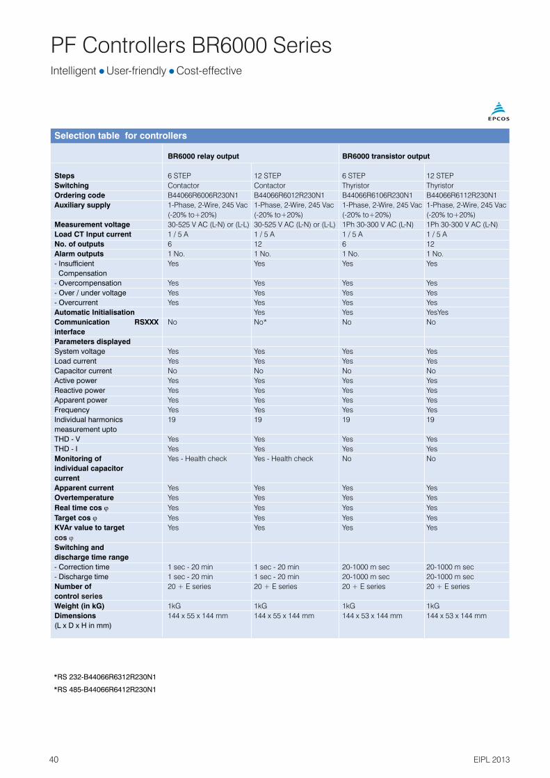
Selection table for controllers
BR6000 relay output BR6000
Steps 6 STEP 12 STEP 6 STEP 12 STEP
Switching Contactor Contactor Thyristor Thyristor
Ordering code B44066R6006R230N1 B44066R6012R230N1 B44066R6106R230N1 B44066R6112R230N1
Auxiliary supply 1-Phase, 2-Wire, 245 Vac 1-Phase, 2-Wire, 245 Vac 1-Phase, 2-Wire, 245 Vac 1-Phase, 2-Wire, 245 Vac
(-20% to+20%) (-20% to+20%) (-20% to+20%) (-20% to+20%)
Measurement voltage 30-525 V AC (L-N) or (L-L) 30-525 V AC (L-N) or (L-L) 1Ph 30-300 V AC (L-N) 1Ph 30-300 V AC (L-N)
Load CT Input current 1 / 5 A 1 / 5 A 1 / 5 A 1 / 5 A
No. of outputs 6 12 6 12
Alarm outputs 1 No. 1 No. 1 No. 1 No.
- Insufficient Yes Yes Yes Yes
Compensation
- Overcompensation Yes Yes Yes Yes
- Over / under voltage Yes Yes Yes Yes
- Overcurrent Yes Yes Yes Yes
Automatic Initialisation Yes Yes YesYes
Communication RSXXX No No* No No
interface
Parameters displayed
System voltage Yes Yes Yes Yes
Load current Yes Yes Yes Yes
Capacitor current No No No No
Active power Yes Yes Yes Yes
Reactive power Yes Yes Yes Yes
Apparent power Yes Yes Yes Yes
Frequency Yes Yes Yes Yes
Individual harmonics 19 19 19 19
measurement upto
THD - V Yes Yes Yes Yes
THD - I Yes Yes Yes Yes
Monitoring of Yes - Health check Yes - Health check No No
individual capacitor
current
Apparent current Yes Yes Yes Yes
Overtemperature Yes Yes Yes Yes
Real time cos j Yes Yes Yes Yes
Target cos j Yes Yes Yes Yes
KVAr value to target Yes Yes Yes Yes
Switching and
discharge time range
- Correction time 1 sec - 20 min 1 sec - 20 min 20-1000 m sec 20-1000 m sec
- Discharge time 1 sec - 20 min 1 sec - 20 min 20-1000 m sec 20-1000 m sec
Number of 20 + E series 20 + E series 20 + E series 20 + E series
control
Weight (in kG) 1kG 1kG 1kG 1kG
Dimensions 144 x 55 x 144 mm 144 x 55 x 144 mm 144 x 53 x 144 mm 144 x 53 x 144 mm
(L x D x H in mm)
transistor output
cos j
series
*RS 232-B44066R6312R230N1
*RS 485-B44066R6412R230N1
Intelligent l lUser-friendly Cost-effective

41EIPL 2013
PF Controllers BR5000 Series
Features Microcontroller logic for
measurements Control mode: Binary, unequal, Preset and user definedMultifunctional LCD displayThree CT sensing for unbalanced loadsDual target Power Factor setting-useful for utility and DG mode operationAutomatic synchronization possibleSeparate 3 CT monitoring of healthiness of capacitor within panelData loggingRS 232 in front and RS 232/485switchable connection at rearStep operation indication on LCD display plus LED which facilitatesviewing from a distanceUnique facility of including ‘FixedCapacitor Bank’ for purpose of Transformer compensation. This can be set such that the controller doesn’t ‘see’ this capacitor
Unique external temperature
Settable alarm facility -undervoltage, overvoltage and so onSettable auxiliary outputs - 2 Nos for Alarm, etc.Auxilary input -1 NoEMI/EMC type testedIndividual Harmonic measurement
thUpto 15
Protection WarningOver / under voltageCapacitor over / under currentOver / under frequencyLoad unbalanceOver temperatureOut of steps (Indication)NV-Ram battery down
Important display parametersVoltageCurrentActive powerReactive powerApparent powerCapacitor currentPer phase values of V, I and neutral currentPower factorFrequencyVTHD
ITHD
Technical DataAuxiliary supply voltage -1Ph, 415V (-40% to + 20%)Measurement voltage: 3PH 3 wire 415 VAC (-40% to + 20%)Current Input - 1A or 5ASteps - 8 and16 relay outputsSupply frequency - 45 Hz to 62 Hz
Mechanical and MaintenanceO OOperating temperature - 0 to 70 C
Storage temperature -O O-10 C to +75 C
Humidity -0 to 98%
Intelligent l lUser-friendly Cost-effective
GeneralThe BR5000 controller series is intended to be used with unbalanced three phase loading conditions and to correct the power factor. The controller needs 3 Load CT inputs and corresponding voltages. The overall compensation is done on averaging basis. The controller is having ultra intelligent processor in built. It covers almost all the electrical parameters to be displayed and monitored .
The three versions of BR5000 Controller are
BR5000 – 16 for contactor switching logic for slow varying loads
BR5000 – 16TX for rapidly changing loading conditions (Option for GSM communication available) BR5000 – HT for High tension upto 33kV sensing of power factors and correction. Version available in8/16 steps.
Dynamic Power Factor Controller (Transistorised) available in 16 steps
Special 8/16 step Controller for Medium Voltage application available

Load CT feedback
SUPPLY
Capacitorcurrent CTfeedback
Note:CT connectionselectable 1A or 5A Example:Select either S1 (1A) or S5 (5A) along with S (common)
L
O
A
D
Panelincomer
330 ohms/3W 0.1 MFD/1kV (recommended)
K1
K1
C1 C2 C3 C4 C5 C6 C7 C8Com
K2 K3 K4 K5 K6 K7 K8
Output commands.
K2 K8
Step-2 Step-8Step-1
N NN
Typical wiring diagram for PF correction : Contactor switching
PF Controller BR5000 Relay Output
Rear side connectionsfor meas. voltage, loadCT sec.and Capacitor CT sec.
YS1
YS5
YPh
BPh
L1
L2BS
1BS5
R
Y
B
N
RS1
RS5
BS
2A
2A
2A
2A
2A
RPh
YS BS
6A
RS
42 EIPL 2013
YS1
YS5
YSRS1
RS5
RSBS1
BS5
Intelligent l lUser-friendly Cost-effective
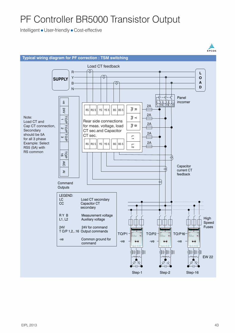
Load CT feedback
Typical wiring diagram for PF correction : TSM switching
T O/P
16
AIC
AI
SUPPLY
L
O
A
D
Panelincomer
Step-16
HighSpeed Fuses
EW 22
Step-2Step-1
T O/P1 T O/P2 T O/P16
-ve -ve -ve
Capacitorcurrent CTfeedback
CommandOutputs
LEGEND:LC Load CT secondaryCC Capacitor CT secondary
R Y B Measurement voltageL1, L2 Auxiliary voltage
24V 24V for commandT O/P 1,2,..16 Output commands
-ve Common ground for command
PF Controller BR5000 Transistor Output
RPh
YPh
BPh
L1
L2
T O/P
2T O
/P3
T O/P
1-ve
24
V
RS 5
RS 5
YS 5
YS 5
BS 5
BS 5
RS
RS
YS
YS
BS
BS
Note:Load CT and Cap CT connection, Secondary should be 5A for all 3 phaseExample: Select RS5 (5A) with RS common
R
Y
B
N
2A
2A
2A
2A
2A
Rear side connectionsfor meas. voltage, loadCT sec.and Capacitor CT sec.
43EIPL 2013
Intelligent l lUser-friendly Cost-effective

PF Controllers BR5000 Series
Selection table for controllers
BR5000 BR5000
Steps 8 STEP 16 STEP 16 STEP
Switching Contactor Contactor Thyristor
Ordering code B44066R5908A415N1 B44066R5916A415N1 B44066R5716A415N1
Auxiliary supply 1Ph 415V (-40% to +20%) 1Ph 415V (-40% to +20%) 1Ph 415V (-40% to +20%)
Measurement voltage 3Ph 3wire 415V (-40% to +20%) 3Ph 3wire 415V (-40% to +20%) 3Ph 3wire 415V (-40% to +20%)
Load CT Input current 1/5 A-separate connectors 1 / 5 A-separate connectors only 5Amp CT secondary
for either of the CT connections for either of the CT connections
No. of outputs 8 Nos. relay o/p of burden 16 Nos. relay o/p of burden 16 digital outputs
1000VA by contactor coils 1000VA by contactor coils maximum 20 mA loading
Alarm outputs 2 Nos. 2 Nos. 1 No.
-Insufficient Yes Yes Yes (only display)
Compensation
-Overcompensation Yes Yes Yes
-Over / under voltage Yes Yes Yes
-Overcurrent Yes Yes Yes
Automatic initialisation No NoNo
Communication RSXXX RS232 and RS485 RS232 and RS485 RS232 and RS485
interface
Parameters displayed --
System voltage Yes Yes Yes
Load current Yes Yes Yes
Capacitor current No No No
Active power Yes Yes Yes
Reactive power Yes Yes Yes
Apparent power Yes Yes Yes
Frequency Yes Yes Yes
Individual harmonics 15 15 15
measurement upto
THD - V Yes Yes Yes
THD - I Yes Yes Yes
Monitoring of Yes - Health check Yes - Health check Yes - total panel capacitor
individual capacitor current monitored
current
Apparent current Yes Yes Yes
Overtemperature Yes Yes (only INT temp.)
Real time cos j Yes Yes Yes
Target cos j Yes (upper and lower target Yes (upper and lower target Yes- (upper and lower target
PF- programmable) PF- programmable) PF- programmable)
KVAr value to target Yes - displayed as Yes - displayed as Yes - displayed as
cos j System reactive power System reactive power System reactive power
Switching and
discharge time range
-Correction time 1 - 240 sec 1 - 240 sec 20-5000 m sec
-Discharge time 1 - 240 sec 1 - 240 sec NA
Number of control series Unequal, Unequal, Binary, unequal
C-series (1-15), E-series C-series (1-15), E-series C-series (1-15), E-series
Weight (in kG) 2.5 kG 2.5 kG 2.5 kG
Dimensions 144 x 155 x 144 mm 144 x 155 x 144 mm 144 x 155 x 144 mm
(L x D x H in mm)
relay output transistor output
44 EIPL 2013
Intelligent l lUser-friendly Cost-effective

PF Controllers BR4000 Series
GeneralThe BR4000 controller series is the most economical series and intended to serve the basic purpose of power factor corrections... The simplest menu driven version controller with navigational keys. The microcontroller based logic, multifunctional display of electrical parameters, compact size 96 x 96 mm and protections makes this controller extremely user friendly.
Intelligent l lUser-friendly Cost-effective
Features Microcontroller logic for
measurements User friendly operationControl mode: binary, unequal, Preset and User definedMultifunctional LCD displaySingle CT sensing for unbalanced loadsCompact 96X96 mm front fasciaSuitable for auto / manual operationIndividual harmonic measurement
thupto 15
Protection WarningOver / under voltageOver / under loadOver temperatureUser friendly operation
Important display parametersVoltageCurrentActive powerReactive power Apparent powerFrequencyVTHD
ITHD
Technical DataMeasurement voltage: 1PH 230 VAC (-25% to +20%) Current input selectable- 1A or 5A for load with class 2 accuracyAuxiliary supply - 1Ph, 230V(-25% to +20%)Steps - 4 and 8 relay outputsSupply frequency -47 Hz to 53 Hz
Mechanical and Maintenance
Compact sizeOperating temperature
O O- 0 to 50 C Storage temperature -
O O-5 C to 65 CHumidity -0 to 98%
BR4000 Controller series is available in 4 stages and 8 stages. Best suited with conventional APFC applications.
45EIPL 2013

PF Controllers BR4000 Series
NC
8
C7
C6
C5
C4
C3
C2
C1
CO
M
L1
S1
S5 S
Output commands to capacitor contactors
Auxiliary and MeasurementVoltage Connection230 V, 1 Phase, 2 Wire
Load CT ConnectionSelectable 1A or 5AExample: Select eitherS1 (1A) or S5 (5A)along with S (common)
Typical wiring diagram for PF correction
Rear side terminals - measurement voltage, measurement current and auxiliary supply
Load sideCapacitor BankAux and
Meas Voltage
L1 (R)
L2 (Y)
L3 (B)
N
L1 N
C1C2C3C4 C8
K1S S1/S5 COM
BR 4008 Controller
2A 6A
PE
Load Current CT
46 EIPL 2013
Intelligent l lUser-friendly Cost-effective

PF Controllers BR4000 Series
BR4000 relay output
Steps 4 STEP 8 STEP
Switching Contactor Contactor
Ordering code B44066R4904A230N1 B44066R4808A230N1
Auxiliary supply / 1-Phase, 2-Wire, 230 Vac (-25% to +20%) 1-Phase, 2-Wire, 230 Vac (-25% to +20%)
Measurement voltage (common for both measurement and auxiliary) (common for both measurement and auxiliary)
Load CT input current 1 / 5 A - separate connectors for 1 / 5 A - separate connectors for
either of the CT connections either of the CT connections
No. of outputs 4 Nos. Relay o/ps of 5A @230V AC Resistive 8 Nos. Relay o/ps of 5A @230V AC Resistive
Alarm outputs No No
-Insufficient compensation Yes (only display) Yes (only display)
-Overcompensation No No
-Over / under voltage Yes (not editable) Yes, programmable
(Factory set UV@170V (P-N) resume@178V,
OV@276V (P-N) resume@264V)
-Overcurrent No Yes, programmable
Automatic initialisation No No
Communication interface RSXXX No No
Parameters displayed
System voltage Yes Yes
Load current Yes Yes
Capacitor current No No
Active power Yes Yes
Reactive power Yes Yes
Apparent power Yes Yes
Frequency Yes Yes
Individual harmonics 15 15
measurement upto
THD - V Yes Yes
THD - I Yes Yes
Monitoring of individual No No
Capacitor current
Apparent current Yes Yes
Overtemperature Yes (only INT temp.) Yes (only INT temp.)
Real time cos j Yes Yes
Target cos j Yes (single target PF - programmable) Yes (upper and lower target PF programmable)
Yes (as system reactive power) Yes (
Switching and
discharge time range
- Correction time 1 - 1200 sec 1 - 65530 sec
- Discharge time 1 - 1200 sec 1 - 65530 sec
Number of control series Only unequal Binary, unequal, C-series, E-series
Weight (in kG) 1 kG 1 kG
Dimensions 96 x 90 x 96 mm 96 x 90 x 96 mm
(L x D x H in mm)
KVAr value to target as cos j system reactive power)
Selection table for controllers
47EIPL 2013
Intelligent l lUser-friendly Cost-effective

48 EIPL 2013
PF Controller BR7000
General
The PF controller BR7000* is a folllow-up development of the PF controller BR6000-series, featuring two devices in one: it can be used as a controller as well as a grid measuring tool.
The BR7000 offers 15 relay outputsfor the steps and three message/alarm relays. Due to the possibility ofprogramming, the 15 outputs can beused for a broad range of applica-tions, for example:
15 conventional steps, each forone three-phase capacitor
15 steps for single-phase capaci-tors, where each output will switch
a single-phase capacitor to N(usually 5 per phase, balancing ofgrid is possible)
Mixed operation: 6 single-phasecapacitors (2 per phase) for balancing plus 9 steps for conventional compensation(three-phase capacitors)
The controller can be connected to a PC via an RS485 interface. The Windows-based softwareBR7000-SOFT allows the readoutof acquired data. The possibility of graphical display of all values offers a comfortable visualization.
Features
LCD full graphic display128 x 64 dots, 8 linesSelf explanatory menu navigation in five languagesThree-phase measuring and controlling; display of following grid parameters:– Voltage – Current– Frequency– Real power– Reactive power– Apparent power– Power factor– Missing reactive power– Harmonic of voltage and current
(up to 31st)– THD-V– THD-I– TemperatureHELP-button for interactive help text
15 switching outputs3 additional alarm/message relays2 isolated interfacesDetailed error messages with timestampAutomatic initialization/test runAutomatic and manual operation,service operation, expert modeThree-phase and single-phase controlling; mixed mode possibleDisplay and storage of maximumvalues, switching operations andoperating timeDisplay of date and timeTime-controlled functions possibleby internal timerOscilloscope mode for graphical displayQuick programming
15 relay outputs lThree-phase measuring and controlling
l
l
l
l l
l
l
l
l
l
l
l
l
l
l
l
*BR7000 is imported and sold in India.

49EIPL 2013
PF Controller BR7000
BR7000
Supply voltage 110 … 230 V AC 50/60 Hz
Measurement voltage range 3 · 30 … 440 V AC (L-N); 50 … 760 V AC (L-L)
Power consumption < 3 VA
Operating ambient temperature –20 … 60 °C
Display illuminated graphic display, 128 x 64 dots, 8 lines
Large display of 3 grid parameters selection in display editor
Plain language E / ES / GER / RU / TR
In- and outputs
Number of relay outputs 15 switching outputs, freely programmable for switching of 1- or 3-phase capacitors
Number of transistor outputs –
Alarm/message relay 1/1
Additional separate fan relay yes
Interface 2 independent isolated RS485-interfaces
Input 2nd parameter-set switchover target PF yes
Special functions
Measuring three-phase
Controlling single-phase, three-phase, mixed mode
Automatic initialization yes
Test-run of complete PFC-system yes
Quick-program yes
Internal timers yes
Oscilloscope (graphical display) mode yes
Display editor yes
Backwards navigation ESCAPE button yes
HELP button for interactive help text yes
Number of control series 20 series pre-set
Control series editor for free programming yes
15 relay outputs lThree-phase measuring and controlling

PF Controller BR7000
Parameters displayed (three-phase display)
Apparent current (A) real value / large display / in %
Reactive power (KVAr) real value / large display / in %
Active power (kW) real value / large display / in %
Apparent power (kVA) real value / large display / in %
KVAr value to target cos j real value / large display / in %
Energy real value / large display
Frequency real value / large display
Temperature real value / large display
Real-time cos j real value / large display
Target cos j real value / large display
Individual harmonics up to up to 31st, real value / in % / bar graph
THD-V, THD-I real value / in % / bar graph
Time/date yes
Recall recorded values
Min. and maximum voltage yes, with time stamp
Maximum current yes, with time stamp
Maximum active power yes, with time stamp
Maximum reactive power yes, with time stamp
Maximum apparent power yes, with time stamp
Maximum value THD-V, THD-I yes, with time stamp
Maximum temperature (°C) yes, with time stamp
Operation time of all capacitors yes
Number of contactor switching operations yes
Others
Weight 1 kg
Dimensions (h x w x d) 144 x 144 x 60 mm
PC-software included yes
Suitable for dynamic PFC no
Ordering code B44066R7415E230
50 EIPL 2013
15 relay outputs lThree-phase measuring and controlling

PF Controller BR7000
BR7000-SOFT Windows-basedsoftware
This program offers the possibility fora comfortable parameterization,recording, analysis and visualization of grid parameters in online operationvia a PC. It is compatible with PF controllers BR6000-R12/S485 (V5.0 onwards) and series BR7000.
The software allows the recording anda graphical evaluation of all values including export- and print function.The spectrum of harmonics can bedisplayed as bar chart.
The configuration manager is used fora complete read out, editing, storingand writing of all parameters of the PF controller via PC. All data can bestored in a configuration file.
Features
Connection to RS485-busAdministration of several PF controllers possibleConvenient analysis of recorded valuesDirect connection to USB port of aPC via USB adapterCD-ROM included in the delivery ofPF controller BR7000
51
l
l
l
l
l
l
EIPL 2013
15 relay outputs lThree-phase measuring and controlling

Grid Analysis Tool MC7000-3
General
The measuring device MC7000-3*has been developed for three-phase measuring, display andstorage of electric parameters inlow-voltage grids. The Windows-based software (included in the delivery) allows a fast and comfort-able evaluation of the measureddata. Based on the findings of thisevaluation the optimum design fora tailormade PFC solution or theinspection of an existing one iseasily performed. The collecteddata is available in Excel-formatgiving the user further processingoptions. As an additional featurethe MC7000-3 is equipped with an
SD memory card slot. A memorycard (1 GB) for data storage andeasy passing on to a PC is alreadyincluded in the delivery.Featuring an illuminated 128 x 64graphic display and a large numberof configuration options for datacollection, display and storage thenew standard measuring tool is flexible and easy to use in the field.Additionally its compact designand the light weight suitcase makeit easy to transport. A further benefitfor very user is the availability ofnot only English, but also German,Spanish, Russian and Turkish asmenu languages.
Features
Measuring, display and storage ofnumerous parameters– Voltage (3-phase)– Current (3-phase)– Frequency (3-phase)– Active power (3-phase)– Reactive power (3-phase)– Apparent power (3-phase)– Power factor (3-phase)– Active, reactive and apparent
energy– Voltage harmonics (up to 51st)– Harmonics of current (up to 51st)– TDH-V (3-phase)– THD-I (3-phase)– TemperatureComfortable programming ofrecording interval and duration viatimersDisplay and internal storage of maximum values with time stampDisplay of date and timeDisplay of harmonics, bar diagramavailableLarge number of display options e.g.rotating display and adjustment offont size
PC software included
Software for evaluation of grid parameters for Windows operatingsystemAdministration of several projectspossibleGraphical display– Several pre-configured graphical
display of standard values– Graphical display of selected grid
values, large number of configuration options
– Comfortable editing of para metersand time interval
– Display as line graph or bar diagram
– Copy into clipboard and print function available
Mathematical evaluation of measured values– Automatic calculation of required
KVAr (target-cos-jto be set byuser)
– Evaluation of measured harmonicsand recommendation of detuningfactor of a PFC system of calculatedsize
– Influence of detuning on the harmonicsfor the calculated detuningfactor and system size is provided
52
Three-phase measuring lEasy evaluation of data 1GB memory card includedl
ll
l
l
l
l
l
l
l
l
*MC7000-3 is imported and sold in India
EIPL 2013

Grid Analysis Tool MC7000-3
Technical data : Grid analysis tool MC7000-3
Weight
Grid analysis tool MC 7000-3
Approx. 4 kg
Dimensions (h x w x d) Compact light weight plastic suitcase 390 x 310 x 147 mm (outside dimensions)
Operating voltage 110 … 230 V AC ±15%(auxillary voltage)
Power consumption < 5 VA
Frequency 50/60 Hz
Max. measuring voltage1) 3 · 30 … 440 V AC (L-N), 50/60 Hz(3-phase) 3 · 50 … 760 V AC (L-L), 50/60 Hz
Measuring current (3-phase) 30, 300, 3000 A (MiniFlex flexible current clamps, to be ordered separately)
Display Illuminated, full graphic, 128 x 64 dots
Menu D / E / ES / RU / TR
Ambient temperature range –10 ... 50 °C(operation)
Storage temperature range –20 ... 60 °C
Pollution degree 2
Overvoltage class CAT III
Protection degree accord. IP40IEC 60529
Connection N connection mandatory, PE in case N not available
Security IEC 61010-1 :2001, EN 61010-1:2001
Accessories included 3 safety voltage measuring cables 2 m (black, red, violet), 1000 V, CAT IV, incl. high power fuse1 safety voltage measuring line 2 m, blue, 1000 V, CAT III4 safety dolphin clips 1000 V, CAT III, black, red, violet, blueWindows-based software CD-ROMLow power device connectionOrdering code: B44066M7777E230
Accessory mandatory, 3 flexible MiniFlex current clamps, cable 2.8 m, 600 V rms (CAT IV), 1000 V rms (CAT III)but not included Max. 3000 A, sensor 400 mm
Ordering code 1 piece: B44066M1301E230Ordering code 3 pieces: B44066M1303E230
1) Incl. all tolerances and overvoltages
53EIPL 2013
Three-phase measuring lEasy evaluation of data 1GB memory card includedl

Switching Devices - Capacitor Duty Contactors Soft Switching of Capacitor l l lExcellent Damping of Inrush Improved Power Quality UL Certified
General
When a capacitor is switched to anAC voltage, the result is a resonantcircuit damped to a greater or lesserdegree. The switching of capacitorscan cause high inrush currents,particularly when they are switchedin parallel to others already activatedin the power line, and if highshort-circuit powers are present onthe line.
Capacitor contactors with dampingresistors make use of pre-switchingauxiliary contacts. They close beforethe main contacts and pre-loadthe capacitor thus avoiding currentpeak values.
This influences positively the lifeexpectancy of the capacitor significantly in addition to the positive impact on the power quality (avoidingtransients and voltage sags thatotherwise may be caused byswitching in capacitors).
The capacitor duty contactors are offered in two versions, viz Standard series Premium series (imported)
Applications Damping of inrush current in
low-voltage PFC systems For PFC systems with and
without reactors
Features Excellent damping of inrush
current Improved power quality (e.g.
avoidance of voltage sags) Longer useful service life of main
contacts of capacitor contactor Soft switching of capacitor and
thus longer useful service life Enhanced mean life expectancy
of PFC system Reduced ohmic losses Leading contacts with wiper
function Tamper-proof and protected
resistors Easy access for cable connection Voltage range: 400…690 V Output range: 12.5…100 KVAr Series J230 / C240 for all
PFC systems AC6b utilization category
Approvals UL file E224924 NLDX and NLDX 7
for J seriesUL file E334934 NLDX and NLDX 7for C series
54 EIPL 2013

Switching Devices - Capacitor Duty Contactors
Type B44066*****J230
Main contacts S1811 S2411 S3211 S5011 S6211 S7411 S90111) 1) 1) 1) 1) 1) 1)Rated insulation voltage V V [V AC] 690 690 690 690 690 690 1,000I IS
Admissible frequency of operation 1/h 120 120 120 120 120 80 80 80
Contact life million 0.25 0.15 0.15 0.15 0.15 0.12 0.12 0.12
operations
Cable cross section2Solid or standard [mm ] 1.5–6 2.5–25 2.5–25 4–50 4–50 4–50 0.5–95/10–120 0.5–95/10–1202Flexible [mm ] 1.5–4 2.5–16 2.5–16 10–35 10–35 10–35 0.5–70/10–95 0.5–70/10–952Flexible with multicore cable end [mm ] 1.5–4 2.5–16 2.5–16 6–35 6–35 6–35 0.5–70/10–95 0.5–70/10–95
Cables per clamp 2 1 1 1 1 1 2 2
Operating range of V magnet coils 0.85–1.1 0.85–1.1 0.85–1.1 0.85–1.1 0.85–1.1 0.85–1.1 0.85–1.1 0.85–1.1S
in multiples of control voltage1)Auxiliary contacts
)1 1) 1) 1) 1) 1) 1) 1)Rated insulation voltage V V [V AC] 690 690 690 690 690 690 690 690I IS
Rated current Ith
at ambient temperature
max. 40 °C Icoth [A] 16 10 10 10 10 10 10 10
max. 60 °C Icoth [A] 12 6 6 6 6 6 6 6
Utilization category AC15
220 to 240 V Icoth [A] 12 3 3 3 3 3 3 3
380 to 440 V Icoth [A] 4 2 2 2 2 2 2 2
Short circuit protection
Highest fuse rating Icoth [A] 25 20 20 20 20 20 20 20
slow, gL (gG)
Auxiliary contacts NO/NC 1/1 1/1 1/1 1/1 1/1 1/1 1/1 1/1
S99111)1,000
Technical data : Capacitor duty contactors premium series
IEC 947-4-1, IEC 947-5-1, EN 60947-4-1, EN 60947-5-1, VDE 0660 Dimensional drawing: see datasheet1) Applies to networks with grounded star point, overvoltage category I to IV, pollution severity 3 (industrial standard), Vimp = 8 kV. Values for other conditions on request.
Capacitor power at ambient temperature,voltage, 50/60 Hz Rated current Weight Ordering code
380 – 400 V 415 – 440 V 660 – 690 Vo o o o o o o o50 C 60 C 50 C 60 C 50 C 60 C 50 C 60 C
KVAr KVAr KVAr KVAr KVAr KVAr A A kg
0–12.5 0–12.5 0–13 0–13 0–20 0–20 18 18 0.34 B44066S1811J230
10–20 10–20 10.5–22 10.5–22 17–33 17–33 28 28 0.60 B44066S2411J230
10–25 10–25 10.5–27 10.5–27 17–41 17–41 36 36 0.60 B44066S3211J230
20–33.3 20–33.3 23–36 23–36 36–55 36–55 48 48 1.10 B44066S5011J230
20–50 20–50 23–53 23–53 36–82 36–82 72 72 1.10 B44066S6211J230
20–75 20–60 23–75 23–64 36–120 36–100 108 87 1.10 B44066S7411J230
33–80 33–75 36–82 36–77 57–120 57–120 115 108 2.30 B44066S9011J230*
33–100 33–90 36–103 36–93 57–148 57–148 144 130 2.30 B44066S9911J230*
Main technical parameters 230V coil:
Connection diagram
* without CCC
All types B44066S****J230 (with preload resistors),B44066S1811J230 with wires on the bottom, B44066S9911J230 with resistors inside housing.
2
1 2 3
4 6A 2
AUX
A 1
L 1 L2 L3
55EIPL 2013
Soft Switching of Capacitor l l lExcellent Damping of Inrush Improved Power Quality UL Certified

Switching Devices - Capacitor Duty Contactors
Type B44066*****C240Main contacts C1011 C1211 C1611 C2011 C2511 C3312 C4012 C6012
1) 1) 1) 1) 1) 1) 1) 1)Rated insulation voltage V V [V AC] 690 690 690 690 690 690 690 690I IS
Admissible frequency of operation 1/h 240 240 240 240 240 240 240 100Contact life million operations 0.2 0.2 0.2 0.1 0.1 0.1 0.1 0.1Cable cross section
Flexible with [mm ] 2.5 2.5 4 4 6 16 16 5021 conductor Flexible with [mm ] 1.5 1.5 2.5 4 4 6 6 25
cable end sleeve - 2 conductors2Solid without cable end sleeve - [mm ] 4 4 6 10 16 25 25 5021 conductor Solid without [mm ] 4 4 6 6 10 16 16 35
cable end sleeve - 2 conductorsOperating range of magnet coils 0.78-1.1 0.78-1.1 0.78-1.1 0.78-1.1 0.78-1.1 0.78-1.1 0.78-1.1 0.78-1.1in multiples of control voltage Vs
1)Auxiliary contacts1) 1) 1) 1) 1) 1) 1) 1)Rated insulation voltage V V [V AC] 690 690 690 690 690 690 690 690I is
Rated current I th
at ambient temperature: 40° C Icoth[A] 10 10 10 10 10 10 10 10 60° C Icoth[A] 8 8 8 8 8 8 8 8Utilization category AC15220 ... 240 V Icoth[A] 3 3 3 3 3 3 3 3380 ... 440 V Icoth[A] 1.5 1.5 1.5 1.5 1.5 1.5 1.5 1.5Short circuit protection Icoth[A] 10 10 10 10 10 10 10 10 Highest fuse size, slow, gL (gG)Auxiliary contacts NO 1 1 1 1 1 1 1 1
NC 1 1 1 1 1 2 2 2
2cable end sleeve -
Capacitor power at ambient temperature, voltage, 50 / 60 Hz Rated current Weight Ordering code
380 - 400 V 415 - 440 V 660 - 690 V
55 °C 55 °C 55 °C 55 °C
KVAr KVAr KVAr A kg
0-10 0-10 0-12.5 14 0.43 B44066S1011C240
0-12.5 0-12.5 0-18 18 0.43 B44066S1211C240
0-16.7 0-16.7 0-24 24 0.43 B44066S1611C240
0-20 0-20 0-30 29 0.43 B44066S2011C240
0-25 0-25 0-36 36 0.43 B44066S2511C240
0-33.3 0-33.3 0-48 48 0.43 B44066S3312C240
0-40 0-40 0-58 58 0.43 B44066S4012C240
0-60 0-60 0-92 92 0.43 B44066S6012C240
Main technical parameters 240 V coil:
Connection diagrams
Types B44066S...1C240 Types B44066S...2C240
IEC 947-4-1, IEC 947-5-1, EN 60947-4-1, EN 60947-5-1, VDE 0660 Dimensional drawing: see datasheet1) Applies to networks with grounded star point, overvoltage category I to IV, pollution severity 3 (industrial standard), Vimp = 8 kV. Values for other conditions on request.
AUX
2
1 13
14
31
32
2 3
4 6A 2
AUX
A 1
L 1 L2 L3
Technical data : Capacitor duty contactors standard series
56 EIPL 2013
Soft Switching of Capacitor l l lExcellent Damping of Inrush Improved Power Quality UL Certified

Switching Devices - Thyristor Modulesfor Dynamic PFC TSM Series
GeneralConventional systems for powerfactor correction are used to optimize the power factor and reduce the level of harmonics in the grid. The usage of new technologies in modern industry has negative impacts on electric power quality of the main supply networks, e.g. frequent high load fluctuations and harmonic oscillation.
Excessive currents, increased losses and flickering will not only influence the supply capacity but will also have a significant impact on the operation of sensitive electronic devices.
The solution for this are dynamicpower factor correction systems.With the thyristor module seriesTSM-LC and TSM-HV, we providethe main component – “the electronicswitch” – for dynamic powerfactor correction.The TSM module series offers fastelectronically controlled, self-observing thyristor switches for capacitive loads up to 50 KVAr, thatare capable to switch PFC capacitorswithin a few milliseconds nearlywithout a limitation to the numberof switchings during the capacitorlifetime.
Applications Main supply networks with high
load fluctuations for dynamic PFC systems
Presses Welding machines
Elevators Cranes Wind turbines
Features Easy installation: it can be used
similar to a contactor All the intelligence needed is
offered within the thyristor moduleitself
Reaction time: 5 milliseconds only Permanent self-controlling of:
– voltage parameter– phase sequence– capacitor outputDisplay of– operation– faults– activation
Voltage range: 440 V and 690 V Output range:
440 V: 10, 25 and 50 KVAr690 V: 50 KVAr
Ultrafast Smooth Switching l l lNatural Cooled Compact Design Enhanced Life of System
57EIPL 2013

Switching Devices - Thyristor Modulesfor Dynamic PFC TSM Series
Dynamic PFC network BR5000-T multiple stages
Dynamic PFC network BR6000-T multiple stages
58 EIPL 2013
2A
2A
Ultrafast Smooth Switching l l lNatural Cooled Compact Design Enhanced Life of System

Switching Devices - Thyristor Modulesfor Dynamic PFC TSM Series
Selection table TSM series
TSM-LC 10 TSM-LC 25 TSM-LC 50
Ordering code B44066T0010R440 B44066T0025R440 B44066T0050R440 B44066T0050R690
Rated voltage 380 … 440 V 380 … 440 V 380 … 440 V 690 V
Max. grid voltage: 440 V 440 V 440 V 690 V
– in conventional PFC
systems(without reactors)
– in detuned PFC system 440 V 440 V 440 V 690 V
(7% detuning) (no upwards tolerance) (no upwards tolerance) (no upwards tolerance)
– in detuned PFC 400 V 400 V 400 V 690 V
system (14% detuning)
Frequency 50/60 Hz 50/60 Hz 50/60 Hz 50/60 Hz
Maximum power / 10 KVAr 25 KVAr 50 KVAr 50 KVAr
at nominal voltage
Power circuit Direct connection Direct connection Direct connection Direct connection
4 pole via terminal 4 pole via busbar 4 pole via busbar 4 pole via busbar2 2 2 2clamps (D = 6 mm (cable lug 25mm (cable lug 25mm (cable lug 25mm
2resp. 4 mm ) D =8 mm) D =8 mm) D =8 mm)
Neutral required No* No* No* Yes**
Aux. supply voltage No No No 230 V AC
required
Connection from bottom from bottom from bottom from bottom
Losses (PD in W) 2.0 x l (in A) typical; 2.0 x l (in A) typical; 2.0 x l (in A) typical; 3.0 x l (in A) typical; at
35 W (thermal) 75 W (thermal) 150 W (thermal) 690 V/ 50 KVAr approx.
125 W (thermal)
Recommended fuses 3 x BS Type 3 x BS Type 3 x BS Type 3 x BS Type
“superfast” (AC 690 V) 40 A (AC 690 V) 80 A (AC 690 V) 160 A (AC 690 V)
Dimensions in mm 163 x 150 x 75 157 x 200 x 180 157 x 200 x 180 157 x 200 x 195
(w x h x d )
Weight 1.75 kg 4.8 kg 4.8 kg 5 kg
LED display per phase 2 2 2 1
Cascading yes yes yes yes
Ambient temperature –10 °C ... 55 °C –10 °C ... 55 °C –10 °C ... 55 °C –10 °C ... 55 °C
Discharge resistors 1 1 1 Standard resistor
EW-22 needed sufficient
Three phase current 1 1 1 1
limitation reactor needed***
TSM-HV 50
*For operation with three-phase capacitor or three single-phase capacitors. **Only for and compulsorily for operation with single-phase capacitors. ***For PFC systems without detuning reactors mandatory.
Type/Description Ordering CodeDischarge resistors EW-22 at least 1 piece per step B44066T0022S400to be used for all types of TSM-LC if fast re-switching timeis required. For higher rated steps please contact yourlocal sales office.
EW-22:Dimensions (w x d x h) : 90 x 50 x 100 mmWeight (approx.) : 0.3 kgDesign panel : for mounting on heat sink/fittingConnection : wago terminal, ready for three-phase connection to the capacitor
Note :Three phase current limitation reactor for thyristor modulesTSM-series in conventional dynamic PFC-systems without reactor is a mustUsed for limitation of the pace of current increase di/dT in the thyristorsto the maximum permissible value
Accessories for TSM-LC modules
59EIPL 2013
Ultrafast Smooth Switching l l lNatural Cooled Compact Design Enhanced Life of System

Technical Data
Input signal 24 VDC 3V, 15mA
Output voltage Maximum 1V drop
on input signal
Output current 100mA max.
Output type Transistor output
Number of inputs 16
Number of outputs 16o o
Temperature range 0 C to 60 C
Mounting Din Rail mounting
Dimensions (L x W x H) 72 x 125 x 125 mm
Total weight (kG) 0.4 kG (approx)
±
Features Transistorised output for fast switching Short circuit protection for outputs Standard DIN rail mount design provides for easy mounting
From SMPS
To TSMModule
From SMPS
- VE
- VE
I/P16
+24V
+24V
O/P16
O/P1I/P1
From APFCController
Output Buffer card
Dimensions and Connection
Buffer Card
9 10 11 12 13 14 15 16
1 2 3 4 5 6 7 8
72
Front View
1
25
BUFFER CARD 16 STEPS
72
Top View
1
25
125
Side View
1
25
1
15
4
4
37
4
4
60 EIPL 2013
Current amplifier for TSM application lShort circuit protected

Reactors - Antiresonance Harmonic Filter
GeneralThe increasing use of modern power electronic apparatus (drives, uninterruptible power supplies, etc.)produces nonlinear current andthus influences and loads the network with harmonics (line pollution).
The power factor correction or capacitance of the power capacitorforms a resonant circuit in conjunction with the feeding transformer. Experienceshows that the self-resonantfrequency of this circuit is typically between 250 and 500 Hz, i.e. in the region of the 5th and 7th harmonics.
Such a resonance although can leadto the following undesirable effects:– overloading of capacitors,– overloading of transformers and
transmission equipment,– interference with metering and
control systems, computers andelectrical gear,
– resonance elevation, i.e. amplification of harmonics,
– voltage distortion.
These resonance phenomena canbe avoided by connecting capacitorsin series with filter reactors inthe PFC system. These so called“detuned” PFC systems are scaledin a way that the self-resonant
frequency is below the lowest line harmonic. The detuned PFC system is purely inductive seen by harmonics above this frequency. For the base line frequency (50 or 60 Hz usually), the detuned system on the other hand acts purely capacitive, thus correcting the reactive power.
Applications Avoidance of resonance
conditions Tuned and detuned harmonic
filters Reduction of harmonic distortion
(network clearing) Reduction of power losses
Features High harmonic loading capability Very low losses High linearity to avoid choke tilt Low noise Convenient mounting Long expected life time Temperature protection (NC contact)
* According to DIN ENV VV61000-2-2
Type tested at CPRI ’H’ Class insulation Thermal Micro Switch Linearity 173%l l l ≥
Technical data and limit values
Three-phase filter reactors to EN 60289
Filter reactors
Harmonics* V = 0.5% V (duty cycle = 100%)3 R
V = 6.0% V (duty cycle = 100%)5 R
V = 5.0% V (duty cycle = 100%)7 R
V = 3.5% V (duty cycle = 100%)11 R
V = 3.0% V (duty cycle = 100%)13 R
22 2Effective current Irms = (I +I ... I )1 3 13
Fundamental current I = 1.06 · I (50 Hz or 60 Hz current of capacitor)1 R
Temperature protection microswitch (NC)
Dimensional drawings and terminals see page 62 and 63
Frequency 50 Hz or 60 Hz
Voltage 230, 380, 400, 415, 440, 690, 750, 800, 1000
Output 5 … 100 KVAr
Detuning 5.67%, 7%, 14%
Cooling natural
Ambient temperature 40 °C
Class of insulation H
Enclosure IP00
√
61EIPL 2013

KVAr Material Code Rated Current (A) I rms (A) Inductance (mH) Terminations
5 B44066D7005K440N1 6.6 7.45 9.28 CU. 6/6 Sq. mm
10 B44066D7010K440N1 13.2 14.9 4.65 CU. 6/6 Sq. mm
12.5 B44066D7012K440N1 16.5 18.7 3.71 CU. 6/6 Sq. mm
15 B44066D7015K440N1 19.65 22.35 3.1 AL. 8/35 Sq. mm
20 B44066D7020K440N1 26.24 29.78 2.32 AL. 8/35 Sq. mm
25 B44066D7025K440N1 32.8 37.2 1.86 AL. 8/35 Sq. mm
30 B44066D7030K440N1 39.36 44.7 1.55 AL. 8/50 Sq. mm
40 B44066D7040K440N1 52.49 59.6 1.16 AL. 8/50 Sq. mm
50 B44066D7050K440N1 65.61 74.5 0.93 AL. 8/50 Sq. mm
75 B44066D7075E440N1 98.41 111.68 0.62 20X3 CU BUSBAR
100 B44066D7100E440N1 131.22 148.91 0.46 25X3 CU BUSBAR
Rated voltage - 440 V 7% aluminum wound reactors
Rated voltage - 415 V 7% aluminum wound reactors
Electrical Parameters and Terminations
Electrical Parameters and Terminations
KVAr Material Code Rated Current (A) I rms (A) Inductance (mH) Terminations
5 B44066D7005K415N1 6.96 7.89 8.257 CU. 6/6 Sq. mm
10 B44066D7010K415N1 13.91 15.79 4.128 CU. 6/6 Sq. mm
12.5 B44066D7012K415N1 17.39 19.73 3.303 CU. 6/6 Sq. mm
15 B44066D7015K415N1 20.87 23.68 2.752 AL. 8/35 Sq. mm
20 B44066D7020K415N1 27.82 31.58 2.064 AL. 8/35 Sq. mm
25 B44066D7025K415N1 34.78 39.47 1.651 AL. 8/35 Sq. mm
30 B44066D7030K415N1 41.74 47.36 1.376 AL. 8/50 Sq. mm
40 B44066D7040K415N1 55.65 63.15 1.032 AL. 8/50 Sq. mm
50 B44066D7050K415N1 69.56 78.94 0.826 AL. 8/50 Sq. mm
75 B44066D7075E415N1 104.34 118.41 0.55 20x3 CU BUSBAR
100 B44066D7100E415N1 139.12 157.88 0.413 25x3 CU BUSBAR
Reactors - Antiresonance Harmonic Filter
62 EIPL 2013
Reactor dimensional details
L W
e
n2 d2
b
R. H. SIDE VIEWELEVATION
1
n1A 7
open slotd1 x d2 - 4 Nos.
WAGO TERMINALL TYPE
2.5 mm sq/500 V.
l2
d1
H
Type tested at CPRI ’H’ Class insulation Thermal Micro Switch Linearity 173%l l l ≥

Type tested at CPRI ’H’ Class insulation Thermal Micro Switch Linearity 173%l l l ≥

Fundamentals of Power Factor Correction
The rational use of electrical energycalls for economical generation, trans-mission and distribution with little losses. That means restricting all fac-tors in electrical networks that causelosses. One of these factors is laggingreactive power. Loads in industrial andpublic power grids are primarily of anohmic-inductive nature. The purposeof systems for power factor correctionin networks is to compensate the gen-erated lagging reactive power by lead-ing reactive power at defined nodes.This also serves to avoid impermissiblyhigh voltage drops and additionalohmic losses. The necessary leadingpower is produced by capacitors par-allel to the supply network, as close aspossible to the inductive load. Staticcapacitive compensation devices
that an electrical installation operatesmore economically (higher effectivepower for the same apparent power).
Improved voltage quality
Reduced voltage drops
Optimum cable design– Cable cross-sections can be
reduced with improvement of powerfactor (less current). In existing installations for instance, extra orhigher power can be transmitted.
Reduced transmission losses The transmission and switching devices carry less current, i.e. onlythe effective power, meaning that the ohmic losses in the leads are reduced.
l
l
l
l
reduce the lagging reactive powercomponent transmitted over the net-work. If grid conditions change, the required leading reactive power canbe matched in steps by adding or taking out single power capacitors(automatic PFC) to compensate thelagging reactive power.
Benefits of power factor correction
Fast return on investment throughlower power costs – Power factor correction reduces
the reactive power in a system. – Power consumption and thus
power costs drop in proportion.
Effective use of installation An improved power factor means
l
l
Power factor correction systemwith filter circuit reactors for reduction of harmonics.
M3 –
M3 –
PFC controller
Fuses
Capacitorcontactors
Thyristormodules
Reactors
PFCcapacitors
Typical power factor correction circuit diagramm
64 EIPL 2013

Wavy cut design
kWh meter
Apparentpower
Capacitors forcompensation
Grid
kvarh meter
PS
Q
Conventional power factor correction
Section A
Capacitorwindings
Metal spray
Core
Film and film-free margin
Metalization
Metalization
Heavy edge
EPCOS wavy cut
Section A
Without EPCOSwavy cut
Solid contact zone
Crackspossible
Flame-sprayed area
Heavy edge
Flame-sprayedcontact area (Zn)
Large effectivecontact area
Metalization
Components of Power Factor Correction
1. Capacitor
Power factor correction (PFC) capacitorsproduce the necessary leading reactive power to compensate the lagging reactive power. They should be capable of withstanding high inrush currents caused by switching operations (>100 I ). If they are connected in R
parallel, i.e. as banks, the inrush current
lwill increase ( 150 I ) because theR
charging current comes from the power line as well as from other capacitors connected in parallel. Design of capacitors MKK/MKP technologyMetalized plastic compact capacitorswith self-healing properties and apolypropylene dielectric. Film metallization with zinc/aluminum alloyresults in high performance and a low film thickness allowing significantlymore compact dimensionsand a lower weight.A heavy edge and special film-cuttingtechnique (optimized combination ofwavy and smooth cuts) produces amaximum effective surface for themetal spraying or contacting process
l
≥
l
l
l
Series PhaseCap and PhaseCap
HD dry technology – impregnation with an inert gas
(nitrogen N ).2
Series PhaseCap Compact –
semi-dry biodegradable resin.
Series PhiCap – impregnation
with semi-dry biodegradable soft
resin.
MKV technology
Based on oil-impregnated polypropylene - paper capacitor
winding. The winding element consists of double sided
metalized paper as the electrodecarrier and an unmetalized
polypropylene film as the dielectric.This combination is especially well
suited for high power dissipations.
The film-paper arrangement thatforms the winding is wound in a
slightly staggered alignment: one
edge of each double-sided metalized
paper projects from the winding.
The edges are electrically contacted
with vaporized zinc. The Schooping
or metal-spray process uses zinc of
the highest purity.
65EIPL 2013

Components of Power Factor Correction
Safety
Self-healing properties
In the event of thermal or electricaloverload,an electric breakdown occurs. The dielectric in the breakdownchannel is broken down into highlycompressed plasma that explodes outof the breakdown channel and pushesthe dielectric layers apart. The dis-charge continues within the spreadingplasma via the metal layers so that themetal surrounding the faulty area iscompletely burnt out. This producesperfect isolation of the faulty area within microseconds. The self-healingprocess results in negligible capaci-tance loss – less than 100 pF perevent. The capacitor remains fullyfunctional during the entire process.
Overpressure disconnector
At the end of the capacitor’s servicelife or when a high pressure forms inside the can, the overpressure disconnector is activated.
The specially designed cover with an expansion bead (or bellow as shown in lower fig.) moves upwards
separate the wires and disconnectwillthe capacitor safely from the line. Thedisconnector is separated at its breakpoint (small notch) and the flow of current to the capacitor windings isinterrupted.
Caution: To ensure full functionality of an over-pressure disconnector, the following isrequired:
1. The elastic elements must not behindered, i.e.– connecting lines must be flexible
leads (cables),– there must be sufficient space (at
least 20 mm) for expansion abovethe connections (specified for thedifferent models),
– folding beads must not be retained by clamps.
2. The maximum permissible fault current of 10 000 A to the UL 810standard must not be exceeded.
3. Stress parameters of the capacitormust be within the IEC 60831 specification.
Dry technology/vacuum impregnation
The active winding elements are heated and then dried for a defined period. Impregnation is performed under vacuum. In this way, air andmoisture are extracted from the innercapacitor, and oxidation of the electrodes as well as partial discharges are avoided. Afterwards, the capacitorelements are hermetically sealed incases (e.g. aluminum). This elaborateprocess ensures excellent capacitancestability and long useful life.
Self-healing
1 Dielectric2 Metalized electrodes3 Material displacing shock wave4 Ai r gap with metal vapor
5,6 P l asma zone7 B o u ndary layer between gas phase dielectric and plasma8 B r e akdown channel9 G a s phase dielectric
10 Zone of displaced metalization and dielectric (isolating region)
Overpressure disconnector
10 µm
Aluminium Can
A B
Bellow
Terminal
Snapped connection
A Safety device
2. Power factor controller Modern PF controllers are micropro-
cessor based. The microprocessor analyzes the signal from a current transformer and produces switching commands to control the contactors
that add or remove capacitor stages.
Intelligent control by microprocessor based PF controllers ensures even
, utilization of capacitor stages a minimized number of switching operations and an optimized life
.cycle of the capacitor bank
After the required capacitor output , has been determined the number of . steps should be defined The broad product range of controllers from : EPCOS allows customized solutions
the BR4904 is suited to small PFC .systems with four steps
66
30 µm
EIPL 2013

Components of Power Factor Correction
for conventional, dynamic andmixed compensation with six andtwelve steps for medium and largesystems respectively.
The PF controller BR7000 with its 15relay outputs offers a broad range ofapplications, e.g. 15 conventionalsteps (each for one three-phase capa citor), 15 steps for single-phasecapacitors or mixed operation (see page 50).
Rule of thumb: the number of stepsdepends on the number of loads, i.e.the more small inductive loads, thehigher the number of steps should be.The switching time is also of major im-portance here: the more frequently acapacitor is switched, the more stressis placed on it and its contactors.
3. Multi measuring device
An external meter combining severalfeatures in a single device. Combinedwith the appropriate PF controller, it allows the monitoring, display andstorage of various grid parameters. Itprovides additional protection for thecapacitor and the PFC system. As astandalone solution, it acts as a meter,a signal trigger for thyristor modules oras a switch.
4. MC7000-3 grid analyzer
Offering three-phase measuring, display and storage of electric para-meters in LV-grids, the MC7000-3,housed in a light-weight suitcase, isthe optimum grid analysis tool for eval-uation of new PFC-system-design orinspection of existing ones. A varietyof accessories that come along withthe device such as SD memory card, Windows-based software andseveral cables and clamps make theMC7000-3 a valuable instrument forPQS.
5. Switching devices
Two types of switching devices areavailable from EPCOS: capacitor con-tactors and thyristor modules. Beforechoosing a switching device for a PFCsystem, the user must consider thenumber of switching operations.
Capacitor contactor
Contactors are electromechanicalswitching elements used to switch capacitors or reactors and capacitorsin standard or detuned PFC systems.The pre-switching auxiliary contacts of EPCOS capacitor contactors closebefore the main contact and avoidpeak current values by pre-loading thecapacitor. Note: Even when using capacitor contactors, it is important notto exceed the annual switching capa-bility of the particular capacitor series.
Thryristor modules
Fast-changing loads of any kind require technologies that act in realtime. In dynamic PFC systems, thyristor modules replace slow-actingelectromechanical switches. This notonly allows them to react within a fewmilliseconds, but also increases the lifeexpectancy of all components withoutany mechanical wear out of thethyristor module.Note: A dynamic PF controller is required, e.g. of the BR6000-T series.
6. Reactors (compensation and filtering)
Power distribution networks are in-creasingly subjected to harmonic pol-lution from modern power electronicsdevices, known as non-linear loads,e.g. drives, uninterruptible power sup-plies and electronic ballasts. Harmonicsare dangerous for capacitors con-nected in the PFC circuit, especially ifthey operate at a resonant frequency.The series connection of a reactor and capacitor to detune the seriesresonant frequency (the capacitor’sresonant frequency) helps to preventca pacitor damage. The most criticalfrequencies are the 5th and 7th har-monics (250 and 350 Hz at 50 Hz gridfrequency). Detuned capacitor banks also help to reduce the harmonic
distortion level and clean the network.
A ppropriate ventilation/air circulationis must, when system is with detunedharmonic filter reactor and capacitor
7. Discharge devices
Discharge resistors
Discharge resistors are required to discharge capacitors and protecthuman beings against electric shockhazards as well as to switch capacitorsin automatic PFC equipment(opposing phase).EPCOS discharge resistors are designed to discharge capacitors to 50 V or less within 60 seconds.
Before switching on again, capacitors must be discharged to 10% or less of their nominal voltage.Discharge resistors are included inthe scope of delivery, pre-mountedfor the PhaseCap Premium, PhaseCap Compact, PhaseCap HD,PhiCap B32344 series and MKV- capacitors.
Caution: Discharge and short-circuit the capacitor before handling it!
Discharge reactor
Whenever fast discharge of a capacitoris required, a discharge resistor isnot sufficient. Discharge reactors mustbe used to allow a discharge of withina few seconds. Also, the various stepsin a PFC system can then be switchedmuch faster, minimizing losses at thesame time.
8. Protection
An HRC fuse or MCCB acts as a safetydevice for short-circuit protection.
HRC fuses do not protect a ca pac itoragainst overload – they are designedfor short-circuit protection only.
The HRC fuse rating should be 1.6to 1.8 times the nominal capacitorcurrent.
Caution:
Caution:
Do not use HRC fuses for switching(risk of arcing!).
l
l
l
l
l
l
The BR6000 series is available
67EIPL 2013

Standard Values: Selection Tables for Cables,Cable Cross Sections and Fuses
Selection table
Power Current Cross section Fuse rating
KVAr
Rated voltage 230 V, 50 Hz
2.5 6.3 1.5 10
5.0 12.6 4.0 25
7.5 18.8 6.0 35
10.0 25.1 10.0 50
12.5 31.4 16.0 50
15.0 37.7 16.0 63
20.0 50.2 25.0 80
25.0 62.8 35.0 100
30.0 75.8 50.0 125
40.0 100.4 70.0 160
50.0 125.5 95.0 200
75.0 188.3 185.0 315
100.0 251.0 2 x 120.0 400
125.0 - - -
150.0 - - -
175.0 - - -
200.0 - - -
Rated voltage 400 V, 50 Hz
2.5 3.6 1.5 10
5.0 7.2 2.5 16
7.5 10.8 2.5 16
10.0 14.4 4.0 25
12.5 18.0 6.0 35
15.0 28.8 10.0 50
25.0 36.0 16.0 63
30.0 43.2 25.0 80
40.0 57.6 35.0 100
50.0 72.0 50.0 125
75.0 108.3 70.0 160
100.0 144.3 120.0 250
125.0 180.3 185.0 315
150.0 216.5 2 x 95.0 350
175.0 252.6 2 x 95.0 4002 x 120.0 200.0 288.0 500
Rated voltage 440 V, 50 Hz
2.5 3.3 1.5 10
5.0 6.6 2.5 16
7.5 10.0 2.5 16
10.0 13.2 4.0 25
12.5 16.8 4.0 25
15.0 19.8 6.0 35
20.0 26.4 10.0 50
25.0 33.0 16.0 63
30.0 39.6 25.0 80
40.0 52.8 35.0 100
50.0 66.0 50.0 125
75.0 99.0 70.0 160
100.0 132.0 95.0 200
125.0 165.0 185.0 315
150.0 198.0 2 x 95.0 350
175.0 231.0 2 x 95.0 400
200.0 264.0 2 x 120.0 500
2 A mm A
The above mentioned values are guidelines for operation in normal conditions at ambient temperatures up to 35 °C.Upgrade accordingly if conditions differ, e.g. temperature or harmonics differ. The internal wiring of a capacitor bank is sometimes possible with a smallercross section. Various parameters such as temperature inside the cabinet, cable quality, maximum cable insulation temperature, single or multi corecable, cable length and laying system have to be considered for a proper selection. The local panelbuilder/installer is responsible for a proper selection
of the cable sizes and fuses according to the valid regulations and standards in the specific country where the PFC panels are installed.
68 EIPL 2013

Standard Values: Selection Tables for Cables,Cable Cross Sections and Fuses
Selection table
Power Current Cross section Fuse rating2KVAr A mm A
Rated voltage 480 V, 50 Hz
2.5 3.0 1.5 10
5.0 6.0 2.5 16
7.5 9.0 2.5 16
10.0 12.0 4.0 25
12.5 18.0 6.0 35
15.0 21.0 6.0 35
20.0 24.0 10.0 50
25.0 30.0 10.0 50
30.0 36.0 16.0 63
40.0 48.0 25.0 80
50.0 60.0 35.0 100
75.0 90.0 70.0 160
100.0 120.0 95.0 200
125.0 150.0 120.0 250
150.0 180.0 185.0 315
175.0 210.0 2 x 95.0 350
200.0 240.0 2 x 95.0 400
Rated voltage 525 V, 50 Hz
2.5 2.7 1.5 10
5.0 5.5 1.5 10
7.5 6.9 2.5 16
10.0 11.0 2.5 16
12.5 13.7 4.0 25
15.0 16.5 4.0 25
20.0 22.0 6.0 35
25.0 27.5 10.0 50
30.0 33.0 16.0 63
40.0 44.0 25.0 80
50.0 55.0 35.0 100
75.0 82.5 70.0 160
100.0 110.0 95.0 200
125.0 137.5 95.0 200
150.0 165.0 185.0 300
175.0 193.0 2 x 95.0 350
200.0 220.0 2 x 95.0 350
Rated voltage 690 V, 50 Hz
2.5 2.1 1.5 10
5.0 4.2 1.5 10
7.5 6.3 1.5 10
10.0 8.4 2.5 16
12.5 10.5 2.5 16
15.0 12.6 4.0 25
20.0 16.7 4.0 25
25.0 20.9 6.0 35
30.0 25.1 10.0 50
40.0 33.5 16.0 63
50.0 41.8 25.0 80
75.0 62.8 50.0 125
100.0 83.7 70.0 160
125.0 105.0 70.0 160
150.0 126.0 95.0 200
175.0 146.0 120.0 250
200.0 167.0 128.5 315
The above mentioned values are guidelines for operation in normal conditions at ambient temperatures up to 35 °C.Upgrade accordingly if conditions differ, e.g. temperature or harmonics differ. The internal wiring of a capacitor bank is sometimes possible with a smallercross section. Various parameters such as temperature inside the cabinet, cable quality, maximum cable insulation temperature, single or multi core
of the cable sizes and fuses according to the valid regulations and standards in the specific country where the PFC panels are installed.cable, cable length and laying system have to be considered for a proper selection. The local panelbuilder/installer is
responsible for a proper selection
69EIPL 2013

Q =P x F(0.96)=...(KVAr)c mot
100 x 1.01=101.0 KVAr
<_Cos j 1
70 EIPL 2013

Approximate values (specified by the German Electricity Association VDEW) for fixed PFC of motors
Motor nominal rating Capacitor power rating
(750 r.p.m.*)(1500 r.p.m.*) (1000 r.p.m.*)KVAr KVAr KVAr
1 … 1.9 0.5 0.5 0.6
2 … 2.9 1 1. 1 1.2
3 … 3.9 1.5 1.6 1.7
4 … 4.9 2 2.1 2.3
5 … 5.9 2.5 2.6 2.9
6 … 7.9 3 3.2 3.5
8 … 10.9 4 4.2 4.6
11 … 13.9 5 5.3 5.8
14 … 17.9 6 6.3 6.9
18 … 21.9 7.5 8.0 8.6
22 … 29.9 10 10.5 11.5
30 … 39.9 approx. 40% of the motor power
40 and above approx. 35% of the motor power
*r.p.m.: revolutions per minute
Capacitor power rating Capacitor power rating
Individual PFC for Motors
The capacitor output should beapprox. 90% of the apparent powerof the motor when idle.
This means a power factor of 0.9 at full load and 0.95…0.98 during idling. Important: The capacitoroutput must not be rated too high forindividual compensated machineswhere the capacitor is directly connected with the motor clamp.
This especially applies when the machine has a big oscillating weight and still continues to rotate after switching off. The capacitor placed in parallel may act as generator for the motor which will cause seriousovervoltages.
The consequence could be heavy damage to the capacitor as well as to the motor.
71EIPL 2013

For an exact calculation of the rightcapacitor value, following formulacan be used:
Q = needed capacitor (KVAr)c
I %= magnetising current of0
the transformer AN = apparent rated power of the transformer in KVA
Standard values for transformers power factor correction
Rated apparent power
of transformer for oil immersed transformer for cast resin transformer
KVAr KVAr KVAr
10 1.0 1.5
20 2.0 1.7
50 4.0 2.0
75 5.0 2.5
100 5.0 2.5
160 7.0 4.0
200 7.5 5.0
250 8.0 7.5
315 10.0 8.0
400 12.5 8.5
500 15.0 10.0
630 17.5 12.5
800 20.0 15.0
1000 25.0 16.7
1250 30.0 20.0
1600 35.0 22.0
2000 40.0 25.0
2500 50.0 35.0
3150 60.0 50.0
Rated capacitor power Rated capacitor power
Individual PFC for Transformers
There are regional differences in the guidelines of power suppliersconcerning the admissible size ofcapacitors directly connected witha transformer. Therefore a consultation with the respective power supplier is recommended
before bank. Modern transformers havelaminations which only need lowcapacity to reverse the magnetism.In case the capacitor output is toohigh, stress increase may occurduring idling.
installation of a compensation
72 EIPL 2013

Detuned PFC in General
When installing capacitors for PFCpurpose, the problem of dealing withharmonics has to be faced. They haveto be taken into account when design-ing the PFC system in order to preventparallel and / or series resonance con-ditions that would damage the wholeelectrical system.
When PFC capacitors are connec ted,the inductance of the transformer to-gether with the capacitors forms a reso-nant circuit that could be excited by aharmonic current generated by the load.This resonant circuit has a resonancefrequency, and if a harmonic current ofthis frequency (or close to it) exists, it willlead the circuit into a resonance condi-tion where high current will flow throughthe branches (L: the transformer, and C: the capacitor bank), overloading themand raising the voltage across them andacross the whole electrical system that isconnected in parallel.
PFC detuned filtering is a technique tocorrect the power factor avoiding therisk of resonance condition performedby shifting the resonance frequency to lower values where no harmoniccurrents are present.
This is achieved by modifying thebasic LC circuit formed by the trans-former and the capacitor bank, intro-ducing a filter reactor in series with thecapacitors, making this way a morecomplex resonant circuit but with thedesired feature of having a resonancefrequency below the first existing har-monic. This way it’s not possible tohave a real resonance condition.
Besides this main objective, the reacttor connected in series with capacitorsform a series resonant circuit with acertain tuning frequency at which thebranch will offfer a low impedancepath. Filtering of harmonic currentsand “cleaning” of the grid will beachieved.
Components for PFC detuned filtersmust be carefully selected accordingto the desired PFC purpose, to theharmonics present in the system, tosome features of the system like shortcircuit power and impedances, to the desired filtering effect and to thecharacteristics of the resonant circuitconfigured.
For example, the voltage across thecapacitors will be higher than thenominal grid voltage when they have areactor connected in series.
The reactors must be selected in linewith the inductance value to obtain thedesired tuning frequency and currentcapabi lity high enough for the harmoniccurrent absorption that can be expected.The tuning frequency is usuallyindirectly referred to as the detuningfactor p and expressed as percentage.
PFC detuned filtering is an engi neeringspeciality that takes experiencedknow-how to implement it in a satisfy-ing and safe way.
The design instructions for detunedPFC systems on page 74 to 77 have to be followed to ensure an optimum performance of the PFC system.
Note: The recommendations given inthe selection tables are meant as asupport tool. EPCOS does not takeover any responsibility for the design,as apart from the theoretical conditionsthe prevailing circumstances in theapplication have to be taken intoaccount.
73EIPL 2013
f : fundamental frequencyf : tuning frequencyRES

Detuned PFC: Important Facts and Instructions
Important design instructions to be followed for detuned PFC Systems
Determine the necessary effec tivepower (kvar) of the capacitor bankin order to obtain the desired PF.
Design the capacitor stages in sucha way that the sensibility of the bankis around 15–20% of the total avail-able power. It’s not useful to have amore sensitive bank that reacts witha 5 or 10% of the total power be-cause this would lead to a highamount of switching operations,wasting the equipment unnecessari-ly when the real objective is to havea high average PF.
Try to design the bank with standard kvar values of effectivepower steps, preferably multiples of25 kvar.
Measure the presence of harmoniccurrents in the main feeder cable ofthe system without capacitors at allpossible load conditions. Determinefrequency and maximum ampli tudefor every harmonic that could exist.
4
3
2
1
Calcu late the Total Harmonic Distortion of Current THD-I =
Calculate every existing value for
Measure the presence of harmonicvoltages that might come from outside your system, if possible measure the HV side.Calculate the Total Harmonic Distortion of Voltage
Are there harmonics such as
(measured without capacitors)?If YES use PFC-DF and go toconsideration 7.If NO use standard PFC and skipconsiderations 7, 8 and 9.
Is there 3rd harmonic content, ?
If YES use PFC-DF with p = 14%and skip consideration 8.If NO use PFC-DF with p = 7%or 5.67% and go to consideration 8.
7
6
5
THD-V is: 3–7% use PFC-DF with p = 7% >7% use PFC-DF with p = 5.67%>10% ask for special filter design
Select the proper components us-ing EPCOS tables for PFC-DF andstandard values for effective power,the voltage and frequency of yourgrid, and the determined detunedfactor p.
Always use genuine EPCOS appli -cation-specific designed componentsfor PFC-DF. Please observe that re-actors are specified for their effectivepower at grid voltage and frequency.This power will be the real effectivepower of the whole LC set at funda-mental frequency. Capacitors forPFC-DF must be selected for a higher rated voltage than the grid’sbecause of the overvoltage causedby the series connection with the re-actor. Contactors for capacitors aredesigned as application-specific toreduce inrush capacitors currentsand to handle capacitive loads in areliable way.
9
8
10
74 EIPL 2013
1
.100

Capacitor Voltage Rating selection guideline for a Detuned Capacitor Bank
It is necessary to understand the importance of choosing the right voltage rating while using capacitors in a 'Detuned' system. In commonly accepted technical parlance, we say 'voltage drop across the reactor', however, notice that a capacitor and reactor are electrical components with opposite signs, i.e., =jX and -jXcL
Consider an additional overvoltage factor of 10% towards system voltage variation and harmonic loading. Then the design requirement would be 520.43V. Hence it is recommended that the capacitor voltage rating be chosen at the closest standard voltage rating of 525V.
Hence, when you apply a basic voltage divider formula to these impedances, it's obvious that there exists a steady state voltage 'rise' across the capacitor in the circuit.Now the steady state voltage across the capacitor shall beas follows:
7% detuning reactor
7% detuning reactor
Voltage across capacitor=1.075X440=473.12V
Voltage across capacitor=1.075X415=446.24V
System voltage440V
System voltage415V
Consider an additional overvoltage factor of 10% towards system voltage variation and harmonic loading. Then the design requirement would be 490.86V. Hence it is recommended that the capacitor voltage rating be chosen at the closest standard voltage rating of 500V, or atleast 480V.
Example with p=7% detuning reactor, X =100Ù and X =7ÙC L
Where X = p. XL C
_ j X C
_ j 100
V = cap
V = cap
p = Detuning percentage
_ j X j X+ LC
_ j 100 j 7+
x 1pu
x 1pu = 1.075 pu
75EIPL 2013
General

_ j 100V = cap _ j 100 j 14+
x 1pu = 1.63 pu
Capacitor Voltage Rating selection guideline for a Detuned Capacitor Bank
Consider an additional overvoltage factor of 10% towards system voltage variation and harmonic loading. Then the design requirement would be 562.79V. Hence it is recommended that the capacitor voltage rating be chosen at the closest standard voltage rating of 600V.
14% detuning reactor
14% detuning reactor
Voltage across capacitor=1.163X440=511.63V
Voltage across capacitor=1.163X415=482.56
System voltage440V
System voltage415V Consider an additional overvoltage
factor of 10% towards system voltage variation and harmonic loading. Then the design requirement would be 530.81V. Hence it is recommended that the capacitor voltage rating be chosen at the closest standard voltage rating of 525V.
Example with p=14% detuning reactor, X =100Ù and X =14ÙC L
76 EIPL 2013

Capacitor Voltage Rating selection guideline for a Detuned Capacitor Bank
5.67% detuning reactor
5.67% detuning reactor
Voltage across capacitor=1.06X440=466.45V
Voltage across capacitor=1.06X415=439.94V
System voltage440V
System voltage415V
Consider an additional overvoltage factor of 20% towards system voltage variation and harmonic loading. Notice the difference between the previous considerations of detuning. This is due to the fact that the detuning frequency has shifted
thupwards, more closer towards the 5 Harmonic frequency. This behaves
thlike a partially tuned filter for the 5 Harmonic frequency. Then the design requirement would be 559.74V. Hence it is recommended that the capacitor voltage rating be chosen at the closest standard voltage rating of 600V. It is also preferred that the type of capacitor chosen is one which has a reasonably larger overcurrent capability as well.
Consider an additional overvoltage factor of 20% towards system voltage variation and harmonic loading. Notice the difference between the previous considerations of detuning. This is due to the fact that the detuning frequency has shifted
thupwards, more closer towards the 5 Harmonic frequency. This behaves
thlike a partially tuned filter for the 5 Harmonic frequency. Then the design requirement would be 527.93V. Hence it is recommended that the capacitor voltage rating be chosen at the closest standard voltage rating of 525V. It is also preferred that the type of capacitor chosen is one which has a reasonably larger overcurrent capability as well.
Example with p= 5.67% detuning reactor, X =100Ù and X =5.67ÙC L
_ j 100V = cap _ j 100 5.67+
x 1pu = 1.06 pu
77EIPL 2013

Dynamic PFC:Important Facts and Instructions
shortens the life expectancy of the capacitor, but also increases the riskof premature failure and in the worstcase represents a potential safety risk.
But furthermore the capacitor itself isspecified for a limited number ofswitching operations per year. Thestandard IEC 60831 gives an accept-able value of 5 000 switching opera-tions per year, a value far belowswitching numbers up to 100 000 thatmay be required per year in dynamicapplications. Such large switchingnumbers and the respective overvolt-ages and overcurrents during eachswitching operation are likely to dam-age the capacitor and may lead to avery early capacitor failure.
In dynamic PFC systems, the capaci-tor contactors are replaced by thyris-tor modules that are suitable for anearby unlimited number of switchingoperations as there is no mechanicalwear-off. Thyristor modules featureelectronic semiconductor switchesthat are able to react to a changing re-active power demand on the ms scaleand that can switch capacitors withoutadditional stress. The EPCOS TSM-thyristor switches keep the capacitorsat the peak value of the grid voltageand connect them only when the gridreaches this peak voltage value. Thusthe capacitors are switched currentfree and inrush currents that can reachvalues of 200 times the nominal cur-rent for conventional contactors areavoided. Additionally capacitor dis-
charge times up to 50 sec as necessaryfor conventional PFC is not requiredhere.
In summary dynamic PFC does notonly prevent wear-off of the capacitorsand the switches and increases thusthe lifetime of a PFC system and itssafety. It also increases the powerquality in the grid essentially as it canalmost react in real time to reactivepower demands. Fast enough for ex-ample, to take care of motor start upeffects or spot welding requirements.
EPCOS offers all necessary key com-ponents to set up a dynamic PFC sys-tems as the thyristor modules (TSM,see page 57), the required fast transis-tor output controllers (BR6000-T, page38), and the EPCOS standard reactor(page 60) and of course capacitor series (page 12).
General
Conventional PFC systems quicklyreach their limits when they have todeal with fast changing loads. Applica-tions like rolling mills, steel presses,wind turbines, container cranes andlarge buildings include a huge amountof electric consumers that require a reactive power adjustment on the msscale. Production equipment, eleva-tors, chillers, and other electric de-vices not only require such dynamicreactions of the power factor compen-sation equipment, they also lead verysoon to a total number of switchingsthat exceeds the specifications ofstandard electromechanical contac-tors by far.
In conventional PFC systems, stan-dard capacitor contactors are used toswitch capacitor steps on and off.These electromechanical devices offerbetween 100 000 and 200000switching operations in total duringtheir life time which means that in suchan application they reach their life ex-pectancy after 1 to 2 years already. Ithas to be mentioned that capacitorsare much stricter limited with regard to the permitted annual number ofswitching operations (IEC 60831). Thistypically results in destruction of theirinrush current damping capability andmay also damage the contacts in themain power circuit. Burnt main con-tacts may produce oscillation or “un-clean” (re-bouncing) switching opera-tions. This massive overload not only
78 EIPL 2013

PFC Basic Formulae
Apparent Power
The apparent power is the power delivered to an electric circuit.
=S . . .3 V I (VA)
Formula 3
Connection and rating of capacitors
The reactive power of the capacitor is a function of its rated voltage andcurrent.
QC = VC · IC [VAr]
Formula 6
VC · 2V (V )C CQC = –––––––– = –––––X XC C
Formula 7
Formula 8
f: fre q u ency of networkXC: impedance of capacitorC: capacitance value
Formula (7) and (8) together
QC = (V 2)C · · C = (V 2)C · 2 · f · C
Formula 9
1 1XC = ––––– = –––––––––· C 2 · f · C
The following electrical formulasmay be used to calculate basic PFCvalues.
Active power
The amount of input power convertedto output power is the active power.
Formula 1
Power factor
The power factor of an AC electricalpower system is defined as the ratioof the real (active) power to the apparent power.
Active power PPower factor = ––––––––––––––– = ––
Apparent power S
Formula 4
Reactive power
The reactive power is the power consumed in an AC circuit due to theexpansion and collapse of magnetic(inductive) and electrostatic (capacitive)fields.
Formula 2
Power Factor Correction
When the AC load is partly capacitiveor inductive, the current waveform isout of phase with the voltage. Thisrequires additional AC current to begenerated that is not consumed bythe load, creating I2R losses in powercables. Capacitors are used to supplyreactive energy to inductive loads.Reactive energy must be produced asclosely as possible to the loads toprevent unnecessary flow of current inthe network. This is known as powerfactor correction.
QC = P · (tan 1 – tan 2 ) [VAr]
Formula 5
QC: reactive power neededP : total active power
: actual angle of cos j actual
: target angle of cos j actual
79EIPL 2013

80
PFC Basic Formulae
Capacitor in three-phase PFC application
Three-phase PFC applications have two types of capacitor connections: star and delta.
From formulae (9), (10) and (11)
Formula 12
VC = VL
Formula 13
From formulae (9), (10) and (13)
Formula 14
QTOT = 3 2(V )· L CDELTA
QTOT QTOTCDELTA = –––––––––– = ––––––––––––––
23·(V )L ·
· ·
23·(V )L · 2 ·f
QTOT = 3 · QC
Formula 10
VC = VL / 3
Formula 11
2(V )LQTOT = 3 · –––––– CSTAR( 3 2)
VNew2 fNewQNew = (––––– ) –––– ·· QC
V fR R
Formula 16
DELTA connection
Delta connection
VL
STAR connection
Star connection
VL
Capacitor output kvar:
From the formula (9), if we find theQnew with ratio: C will be constant.
Example 1:The relationship between active,reactive and real power and cos
In the diagram below, the power triangle shows an initial power factorof 0.70 for a 100 kW (real power) inductive load. The reactive power required by the load is 100 KVAr. By installing a 67-KVAr capacitor, the apparent power is reduced from 142 to 105 KVAr, resulting in a 26% reduction in current. The power factoris improved to 0.95. Formulas used (1), (2), (3) and (4).
Power factor calculations:
Before PFC: 100/142 = 0.70 or 70% After PFC: 100/105 = 0.95 or 95%
Real power = 100 kW
After PFC =105 KVA
Before PFC =142 KVA
Apparent power
Reactive powerBefore: 100 KVAr
Reactive powerAfter: 33 KVAr
Capacitance added = 67 KVAr
As a conclusion formula (12) and (14)
CSTARCDELTA = ––––––3
Formula 15
QTOT QTOTCSTAR = ––––––––– = –––––––––––––2(V )L · 2(V )L · 2 · f
These values are operating conditions:Qnew
Vnew
fnew
These values are the values capacitor is designed:QC
VC
fR
j
: new reactive power: new voltage: new frequency
: rated frequency: rated capacitor voltage: rated capacitor reactive power
EIPL 2013

PFC Basic Formulae
Example 4: Calculating apparent power reduction (S1–S2) in example 2
S1 – S2 = 70 kVA
Thus, additional power of 70 · (0.9) = 63 kW can be suppliedand transferred via the existing network.
S2 = P / cos 2 = 220 / 0.9
= 244 kVA
S1 = P / cos 1 = 220 / 0.7
= 314 kVA
Example 3: Calculating capacitor ratings forDELTA and STAR connections inexample 2
STAR connection:
VL 440VC = –––– = –––– = 254 V
3 3
QTOT QTOTCSTAR = ––––––––– = –––––––––––––2(V )L · 2(V )L · 2 · f
118.8 · 1000CSTAR = –––––––––––––––––
(440)2 · 2 ·50= 1 954 F / Line (phase)µ
CTOT
Example 2: Calculation of capacitor rating forindustrial installation
Given parameters:
Induction motor 220 kW
Network 440 V AC, (line delta) 3-phase
Frequency 50 Hz
Power factor– Current cos 0.7– Target cos 0.9 118.8 kvar
440 V/50Hz
M
220 kWcos ? = 0.7
Cable cross section calculation
Line current drawn by the motor:
I1 uncompensated load (0.7):
220 · 1 000I1 = ––––––––––––––––– = 412 A
3 · 440 · (0.7)
I2 compensated load (0.9):
220 · 1 000I2 = ––––––––––––––––– = 320 A
3 · 440 · (0.9)
Thus, the cable can carry an additional load of 92 A, or the designer can reduce the cable crosssection.
DELTA connection:
VC = VL= 440 V
QTOT QTOTCDELTA = –––––––––– =––––––––––––––23·(V )L
23·(V )L 2 ·f
118.8 · 1 000CDELTA = –––––––––––––––––––––
3· (440)2 ·2 ·50
Target to correct the power factor to 0.9:
cos 1 = 0.7 ta n 1 = 1.02
cos 2 = 0.9 t a n 2 = 0.48
QC = P (tan 1 – tan 2) = 220· 1000 (1.02 – 0.48) = 118.8 KVAr
81EIPL 2013

Cautions
Temperature class of capacitors tostandard IEC 60831-1
Capacitors are divided into tempera-ture classes. Each class is representedby a number followed by a letter, e.g.–40/D. The number is the lowest am-bient temperature at which a capacitormay operate. The upper limit tempera-ture is indicated by the letter (see tableabove).
The useful life of a capacitor dependsvery much on temperature. Propercooling of a capacitor must ensurethat the maximum temperature is notexceeded, other wise useful life is degraded. When configuring a circuit,one should make sure that capacitorsare not subjected to heat from
adjacent components (reactors, busbars, etc). Forced cooling is preferablefor compact designs. And it is highlyinadvisable to arrange capacitors directly above reactors. Exceedingspecified temperature limits may set inworst case the safety device out ofoperation.
Enclosure First digit Second digit
Ip00 No pro t e c t i o n a g a inst finger touch and ingress of No protection against ingress
Ip20 pro t e c t i o n a g a inst finger touch and solid foreign bodies No protection against ingress
Ip41 pro t e c t i o n a g a inst tool touch and solid foreign bodies Deep-water protection
Ip54 pro t e c t i o n a g a inst tool touch and solid foreign bodies Splash-water protection
of water
Temperature class of capacitors (according IEC 60831-1)
Enclosure of capacitors (IPxx)
x. voltage (V )Frequency (50 /60 Hz) Ma rms Max. duration Remarks
Line frequency 1.00 · VR Continuous duty Highest mean during entire operating ti me of capacitor; exceptions (see below) are
admissible for times of < 24 h
Line frequency 1.10 · VR 8 h daily Line voltage fluctuations
Line frequency 1.15 · VR 30 min daily Line voltage fluctuations
Line frequency 1.20 · VR 5 min daily Line voltage fluctuations
Line frequency 1.30 · VR 1 min daily Line voltage fluctuations
Line frequency Such that current does not exceed maximum admissible figure (I =1.3.I )max. Rwith harmonics
Maximum admissible overvoltage
Temperature class Temperature of capacitor surrounding air
Maximum Maximum mean for 24 h Maximum mean for 1 year
B 45 °C 35 °C 2 5 °C
C 50 °C 40 °C 3 0 °C
D 55 °C 45 °C 3 5 °C
of water
pro t e c t i o n a g a inst dust deposit
82
solid foreign bodies
12.5 mm diameter
1mm diameter
1mm diameter,
EIPL 2013

83EIPL 2013
Cautions
Enclosure of capacitors (IPxx)
For different models there are differenttypes of enclosure. The type of enclo-sure is indicated by a designation con-sisting of the two letters IP followed bytwo digits.
Current rating /maximum admissible overcurrent
The rated current (IR) is the current resulting for rated voltage (VR ) and fre-quency (in Hz), excluding transients.Maximum permitted rms current foreach particular capacitor is spe ci fiedin the data sheet. Continuously ex-ceeding of the nominal current willlead to increased self-heating of thecapacitor and reduce life time. Themaxi mum admissible overcurrent (I )max
of 1.3 · IR to IEC 60831 standard is maintained or overachieved by all capacitors in this catalog.The figuresfor over current allow for the combined effects of harmonics, over voltage andcapa citance tolerance.
Maximum admissible overvoltage
Capacitors from EPCOS are suitablefor operation on overvoltages quotedby IEC 60831 (see table). Overvolt-ages higher than 1.15 · VR reduce lifetime of the capacitor and must not occur more than 200 times during life time of capacitor. Overvoltagesabove 1.3 · VR must not occur at all,appropriate overvoltage protection(e.g. against lightning strikes) must be ensured.
Mean life expectancy
The mean life expectancy of powercapacitors is mainly governed by the following factors:– duration of overload,– ambient temperature and the
re sulting case temperature,– maximum rms current and the
resulting case temperature,– voltage height and duration.
The calculated life expectancy of the various series is stated for nominal operating conditions. If componentsare stressed less than the IEC 60831factors, longer useful life can be expected, and a correspondinglyshorter one or increased failure rate ifnominal parameters are exceeded.
Fuse protection
Power capacitors have to be protectedagainst short circuits by fuses orthermal magnetic overcurrent relays.Slow-blow, low- voltage high-breaking-capacity fuses (HRC) are preferable.The fuse rating should be 1. 6 to 1. 8times the rated current of the capacitor. Magnetic short circuit relaysshould be set to between 9 and 12times rated current to prevent themresponding to high inrush currents.Maximum allowed fault current of10 000 A in accord ance with UL 810standard must be ensured by the application design.
HRC fuses must not be usedfor switching. Resulting electricarcing can cause death! It may also cause capacitor failures, andresult, worst case, in capacitorbursting and fire.

84
Cautions
Switching of capacitors
When a capacitor is switched to anAC system, the result is a resonant circuit damped to a greater or lesserdegree. In addition to the rated current,the capacitor accepts a transientcurrent that is a multiple of (up to 200times) its rated current. Fast switching,low-bounce contactors should beused, and have the switching capacityfor capacitive currents stated by theproducer. Special capacitor contactorswith leading contacts that featureprecharging resistors to damp inrushcurrents are recommended. As perIEC 60831 standard, a maximum of5 000 switching operations per year is acceptable. Before considering ahigher number of switching opera-tions, please contact EPCOS.
Discharging
Capacitors must be discharged to amaximum of 10% of rated voltage before they are switched in again.Thisprevents an electric impulse dischargein the application, influences the capacitor’s useful life in PFC systems,and protects against electric shock.The capacitor must be discharged to50 V or less within 1 min. There mustnot be any switch, fuse or any other disconnecting device in the circuit between the power capacitor and thedischarging device. EPCOS suppliescapacitor dis charge re sis tors to all series, alternatively discharge reactorsare available.
Caution: Discharge and shortcircuit capacitor before handling!
Capacitors in networks with harmonics
Harmonics are produced in the opera-tion of electric loads with a non linearvoltage/current characteristic (e.g.rectifiers and inverters for drives,welding apparatus and uninterruptiblepower supplies). Harmonics are sinu-soidal voltages and currents with high-er frequencies of a multiple of the 50 or60 Hz line frequency. In low - voltagethree-phase systems the 5th and 7thharmonics are especially troublesome.Detuned PFC should be used in sys-tems subject to harmonics. This repre-sents a series resonant circuit of pow-er capacitor and reactor. The circuit istuned so that the series resonant fre-quency is below the lowest harmonics
appearing in the system. This pro-duces an inductive response to all fre-quencies above the series resonantfrequency, avoiding resonances withsystem inductances. Depending onthe selected series resonant frequencypart of the harmonic current is taken up by the detuned PFC system.The remainder of the harmonic currentflows into the superordinate system.The use of detuned PFC thus con-tributes to reducing voltage distortionthrough harmonics and lessens thedisturbing effect on proper operationof other electric loads.
Most international standards limitTHD-V on LV side to 5%. However ithas to be noted that in many gridsthese levels are exceeded and evenlower distortion, e.g. 3–4% THD-V cangenerate extreme overcurrents in caseof resonance condition.
Maximum overcurrents as specifiedunder technical data of each seriesmust not be exceeded.
Resonance must be avoided by ap-propriate panel design. Resonancemay cause very high overcurrentswhich can lead to capacitor failures,and worst case, to explosion and fire.
EIPL 2013

85
Cautions
Installation
Specifications like IEC 61921,VDE 0100, VDE 0101, VDE 0560 part4 and 46, EN 60831 and IEC60831apply to the installation and operationof power capacitors. Capacitorsshould be sited in cool and well venti-lated locations away from other heat-radiating elements. Natural heat dissi-pation is generally sufficient for coolingpurposes if enough air is able to flowto and away from them and the capacitors are spaced at least 20 mmapart. Otherwise, in a less well venti-lated environment, forced cooling(fans) will be necessary, scaled so thatthe maximum admissible ambienttemperature is not exceeded.
Useful life of capacitors strongly depends on the operating temperature(refer to page 44, temperature classesof capacitors).
Exceeding maximum allowed temper-ature may set the safety device out ofoperation.
Please read the Installation and Main-tenance Instructionson the internet atwww.epcos.com/pfc.
Note
Products shown in this catalog reflecttypical specifications. You are kindlyrequested to approve our productspecifications or request our approvalfor your specification before ordering.
Mechanical damage
In case of dents or any other mechanical damage, capacitors must not be used at all.
Vibration resistance
The resistance to vibration of capacitors corresponds to IEC 68, part 2–6.
Max. test conditions:
Test duration 2 h
Frequency range 10 ... 55 Hz correspondingto max. 0.7 g
Displacement 0.75 mmamplitude
Because the fixing and the terminals may influence the vibration properties, it is necessary to check stability whena capacitor is built in and exposed to vibration.Irrespective of this, you are advised not to locate capaci-tors where vibration amplitude reaches the maximum instrongly vibrating equipment.
Connection
Make sure connection cables are of flexible type or flexiblecopper bands are used. This is mandatory to allow theoverpressure disconnector work and avoid mechanicalstress on the terminals and feedthroughs.
The connection cables to the capacitor should be designed for a current of at least 1.5 times the rated current so that no heat is conducted into the capacitor. If reactors are used in an application, the distance between reactor and capacitor must be great enough so that no heat of the reactors, which are operating at a much higher temperature level, is conducted via connection cable to the capacitors.
Avoid bending cable lugs, cables or other mechanicalforce on the terminals. Otherwise leakages may set thesafety device out of operation.
Ensure firm fixing of terminals, fixing torque to be appliedas per individual specification.
Maximum specified terminal current (please refer to technical data of specific series) must not be exceeded atany case.
Grounding
The threaded bottom stud of the capacitor has to be used for grounding. In case grounding is done via metalchassis that the capacitor is mounted to, the layer of varnish beneath the washer and nut should be removed.
Storage and operating conditions
Do not use or store capacitors in corrosive atmosphere,especially where chloride gas, sulfide gas, acid, alkali, saltor the like are present. In dusty environments regularmaintenance and cleaning especially of the terminals is re-quired to avoid conductive path between phases and /orphases and ground.
EIPL 2013
Keep at least 20 mm space above the capacitor and do not attach any component on the top. This gap will allow a longitudinal extension of can in order to ensure that over-pressure disconnector can fully extend.

Capacitor Rack Module M V Capacitors
M V Contactors M V Capacitor Switch
AC (mfd) Capacitors
86
Other PFC products in the basket
EIPL 2013

Contacts:
Factory:
EPCOS India Private LimitedPlot No. E22 – 25 MIDC Area,Satpur, Nashik 422007, IndiaT: +91 253 2205 100 F: +91 253 2353 761
EPCOS India Private Limited Plot No -32 Sec. -5Phase –II, HSIIDC Growth Centre Bawal(Haryana) -123501, India T: +91 1284 263 500/600F: +91 1284 263 601
Sales Offices:
North :EPCOS India Private Limited 2nd Floor, Tower - A,C-28, 29,Logix Cyber Park Sector - 62,Noida - 201301, IndiaT: +91 120 450 5801F: +91 120 450 5818
East :EPCOS India Private Limited 49/2, Purnadas Road, 4th floor,Oxford Medical Centre BuildingKolkata 700 029, IndiaT: +91 33 2419 8870F: +91 33 2419 8815 West :EPCOS India Private LimitedAsha House (3rd floor),28, Suren Road (off Mathuradas Vasanji Road) Andheri (East), Mumbai - 400 093, India.T: +91 22 4256 0600F: +91 22 4256 0628
South : EPCOS India Private Limited 14/2, Rajesh Chambers,Brunton Road, Bengaluru 560001, IndiaT: +91 80 4039 0600 F: +91 80 4039 0603
Service Contacts:
Nashik:Plot No. E22 – 25 MIDC Area Satpur, Nashik 422007, India T: +91 253 2205 100/286F: +91 253 2353 [email protected]://www.service.epcos.in
North:EPCOS India Private Limited 2nd Floor, Tower - A, C-28, 29, Logix Cyber Park,Sector - 62, Noida - 201301, IndiaT: +91 120 4505 815F: +91 120 4505 [email protected]
West:EPCOS India Private Limited Asha House (3rd floor),28, Suren Road (off Mathuradas Vasanji Road),Andheri (East), Mumbai - 400 093, India.T: +91 22 4256 0627F: +91 22 4256 [email protected]
South:EPCOS India Private Limited 14/2, Rajesh Chambers, Brunton Road, Bengaluru 560001, India T: +91 80 4039 0645 F: +91 80 4039 [email protected]
EIPL 2013

EPCOS India Pvt. Ltd.A Member of TDK-EPC CorporationSales Head Office:14/2, Rajesh Chambers, Brunton Road, Bengaluru 560001. Tel: +91-80-4039 0640. Fax :+91-80-4039 0603.Email: [email protected].
EIPL- PFC Product Profile 2013 Prudent 012013 01
“Product development is a continuous process. Consequently the data indicated in this catalogue is subject to change without prior notice. For the latest information, contact your local partners.”