Embed Size (px)
Citation preview

The University of Manchester Research
Power-dense Bi-directional DC-DC Converters with HighPerformance InductorsDOI:10.1109/TVT.2019.2943124
Document VersionAccepted author manuscript
Link to publication record in Manchester Research Explorer
Citation for published version (APA):Calderon-Lopez, G., Scotlock, J., Wang, Y., Laird, I., Yuan, X., & Forsyth, A. (2019). Power-dense Bi-directionalDC-DC Converters with High Performance Inductors. IEEE Transactions on Vehicular Technology.https://doi.org/10.1109/TVT.2019.2943124
Published in:IEEE Transactions on Vehicular Technology
Citing this paperPlease note that where the full-text provided on Manchester Research Explorer is the Author Accepted Manuscriptor Proof version this may differ from the final Published version. If citing, it is advised that you check and use thepublisher's definitive version.
General rightsCopyright and moral rights for the publications made accessible in the Research Explorer are retained by theauthors and/or other copyright owners and it is a condition of accessing publications that users recognise andabide by the legal requirements associated with these rights.
Takedown policyIf you believe that this document breaches copyright please refer to the University of Manchester’s TakedownProcedures [http://man.ac.uk/04Y6Bo] or contact [email protected] providingrelevant details, so we can investigate your claim.
Download date:14. Mar. 2022

0018-9545 (c) 2019 IEEE. Personal use is permitted, but republication/redistribution requires IEEE permission. See http://www.ieee.org/publications_standards/publications/rights/index.html for more information.
This article has been accepted for publication in a future issue of this journal, but has not been fully edited. Content may change prior to final publication. Citation information: DOI 10.1109/TVT.2019.2943124, IEEETransactions on Vehicular Technology
Special Section on “Advanced Vehicle Power Propulsion Systems”
Abstract— An investigation is described into the optimization
of multi-phase, high power, bi-directional DC-DC interleaved converters suitable for Electric Vehicle (EV) applications. Two dual-interleaved topologies were considered initially for the optimization, the main difference being the magnetic devices: either discrete inductors (DI) or an Interphase Transformer (IPT). The comparison used a comprehensive multi-objective design optimization procedure for an 80 kW case study. High performance inductors comprising a split-core structure and dual-foil windings to reduce losses, and a 180 C core, enabled the DI to be competitive with IPT in terms of power density and efficiency. The optimized designs are validated experimentally with an 80 kW bi-directional SiC DC-DC converter, achieving a power density of 31.4 kW/L and specific power of 15.7 kW/kg. The study is then extended to 100-kW three and four-phase interleaved topologies.
Index Terms—DC-DC power converters, magnetic cores, DC inductors, design optimization
I. INTRODUCTION
The US DoE has set challenging targets for on-board power electronic systems in EVs: a power density of 13.4 kW/L, efficiency >94%, and specific power of 14.1 kW/kg by 2020, increasing to 100 kW/L by 2025 [1]. This motivates research into high power density bi-directional DC-DC converters for power trains and charging systems. Interleaved topologies at up to 100 kW are strong candidates as they reduce the current rating of the semiconductors and the size of the magnetic components, despite their higher component count and additional control circuitry [2].
This paper investigates the optimization of two dual-interleaved topologies using an 80-kW case study: one with
This work was supported by the UK Engineering and Physical Sciences
Research Council (EPSRC) National Centre for Power Electronics within the Converters Theme [EP/K035096/1] and Converter Architectures [EP/R004137/1].
Copyright © 2015 IEEE. Personal use of this material is permitted. However, permission to use this material for any other purposes must be obtained from the IEEE by sending a request to [email protected].
G. Calderon-Lopez and A. J. Forsyth are with The University of Manchester, Manchester, M13 9PL UK (e-mail: gerardo.calderon-lopez, andrew.forsyth@ manchester.ac.uk).
J. Scoltock is with The University of Sheffield, Sheffield, S1 4DE, UK. (e-mail: [email protected]).
Y. Wang is with the Hardware Department, Zytek Automotive/Continental Engineering Services, WS13 8RY, UK (e-mail: [email protected]).
I. Laird and X. Yuan are with are with the University of Bristol, Bristol BS8 1UB, UK. (e-mail: ian.laird, [email protected])
discrete inductors (DI), and the other with an Interphase Transformer (IPT) and additional filter inductor. The DI topology has been studied extensively, including for automotive applications [3-5], and multi-stage IPT versions have also been reported [6, 7]. The previous work is extended in this study by comparing the magnetic device approaches through a multi-objective design optimization procedure.
Design optimization is now important in power electronics [8, 9], as it offers a systematic framework for determining the optimal design of a converter for given requirements, enabling the comparison of different topologies in terms of key performance metrics such as volume and efficiency, providing also a consistent platform through which the inter-relationships between different design variables, such as switching frequency and magnetics design, can be fully-understood.
The two major contributions of this paper are to provide a basis for the selection of multi-phase interleaved converter topologies for high-power, on-board DC-DC converters, and the demonstration that high temperature, high performance gapped inductors offer a route to higher power densities.
The topologies and their respective magnetic components are discussed in Section II, whilst the optimization is outlined in Section III. Section IV presents the design optimization results for dual-interleaved converters in terms of power density, efficiency, and weight. The experimental validation is provided in Section V. Finally, a 100-kW case study for three multi-phase converters is presented in Section VI.
II. OVERVIEW OF CONVERTER TOPOLOGIES AND OPERATION
Fig. 1 shows the bi-directional dual-interleaved converters. The phases are linked to the low-voltage port VLV by either discrete inductors, Fig. 1(a), or an IPT with an additional filter inductor, Fig. 1(b). Key voltage and current waveforms demonstrate the main differences in operation. There is a 180° phase shift between the switching legs. The switching period is T. Continuous conduction mode is assumed.
SiC MOSFET power modules are used due to their superior switching frequency capability compared to silicon [10, 11]. The inductors comprise tape-wound nanocrystalline cores with Kapton-insulated foil windings, potted with epoxy resin into an aluminum can. The modules and magnetic components are mounted to a liquid-cooled cold plate and ceramic & film capacitors are used for filtering at both voltage ports.
In spite of the higher cost, limited range of shapes and fragile ribbons, nanocrystalline cores offer several advantages
Power-dense Bi-directional DC-DC Converters with High Performance Inductors
Gerardo Calderon-Lopez, James Scoltock, Member, IEEE , Yiren Wang, Ian Laird, Xibo Yuan, Senior Member, IEEE and Andrew J. Forsyth, Senior Member, IEEE

0018-9545 (c) 2019 IEEE. Personal use is permitted, but republication/redistribution requires IEEE permission. See http://www.ieee.org/publications_standards/publications/rights/index.html for more information.
This article has been accepted for publication in a future issue of this journal, but has not been fully edited. Content may change prior to final publication. Citation information: DOI 10.1109/TVT.2019.2943124, IEEETransactions on Vehicular Technology
Special Section on “Advanced Vehicle Power Propulsion Systems”
for high power automotive applications such as relatively low core and a high saturation flux density above 1 T, enabling efficient, compact and light devices with good thermal and mechanical properties. The thermal conductivity of nanocrystalline cores along its laminations is at least twice that of ferrites, 8–10 W/mK [12, 13], and the finished cores are not as brittle as ferrites. Furthermore, cores with maximum operating temperatures of 180 °C are available.
Their increased cost can be recovered indirectly through savings in other components: windings which require fewer turns & smaller copper area, compact cooling hardware and enclosures due to reduced losses and smaller dimensions. Compared to amorphous metal and powder cores, their losses are lower, and unlike powder cores, they do not exhibit a variable inductance depending on the DC current.
To reduce the overall inductor losses, two techniques are implemented: split-cores to lower the gap losses [14], and dual-foil windings to tackle the high-frequency losses in the conductors [15].
A. Topology with Discrete Inductors
In the DI topology, Fig. 1(a), each phase operates independently, with the current ripple in each inductor L1 and L2 as in a standard buck or boost converter. The interleaving cancels the total ripple current on the low-voltage source when the duty cycle D= 0.5. Each inductor has an average DC current of half the total, and the ripple is at the switching frequency, fs.
B. Topology with IPT and Filter Inductor
The IPT requires an additional filter inductor, Fig. 1(b), to reduce the ripple current on the low voltage port. Otherwise, a large ripple current and potentially discontinuous current operation would result due to the small leakage inductance of
the IPT The IPT coupling factor is typically >0.98 to ensure a minimum core volume [16].
The voltages in the IPT nodes, V1 and V2, alternate at the switching frequency with a peak of VHV. The IPT operates as an inductive divider for the differential voltage V12= V1–V2, resulting in a midpoint voltage, VM1, having a peak of VHV/2 at twice the switching frequency. Since the filter inductor faces lower volts-seconds at 2fs, its size can often be reduced significantly, and the topology can achieve higher power densities. Ideally, perfect ripple cancellation occurs at D= 0.5.
C. Magnetics Design
The inverse coupling of the IPT results in DC flux cancellation. However, the high differential voltage across the IPT tends to produce a high AC flux and sufficient turns are required to limit the core losses and prevent saturation. As a result, the IPT self-inductances, La & Lb, are high whilst their AC ripple current is low. Conversely, the DC flux density in the cores of the discrete and filter inductors is relatively high, so their AC flux density is relatively low. The lower AC voltage across the inductors means they require fewer turns, yielding lower inductance and higher AC current ripple.
The losses are due to: the windings, Pw, core, Ph, –which comprise the hysteresis, eddy current and anomalous losses– and gap, Pg, which are induced in the core laminations near the gap by the fringing flux. Core losses in the discrete and filter inductors are usually low, owing to their low AC flux density, whilst the gap loss is high as a result of the large gap required to prevent saturation. In the IPT, the gap loss is low since virtually no air gap is required.
In the context of this work, standard inductor designs comprise a single 155-°C core with single foil windings. Fig. 2 sketches the assembly and winding details of the high-performance inductors. The split-core method [14] uses a
Fig. 1. Schematic of DC-DC converter and magnetic devices.
(a) Inductor assembly with split-core and dual-foil windings.
(b) Cross-section view of a dual-foil winding.
Fig. 2. Details of the high performance inductors.

0018-9545 (c) 2019 IEEE. Personal use is permitted, but republication/redistribution requires IEEE permission. See http://www.ieee.org/publications_standards/publications/rights/index.html for more information.
This article has been accepted for publication in a future issue of this journal, but has not been fully edited. Content may change prior to final publication. Citation information: DOI 10.1109/TVT.2019.2943124, IEEETransactions on Vehicular Technology
Special Section on “Advanced Vehicle Power Propulsion Systems”
number of nanocrystalline cores placed side-by-side with an insulation layer in between, Fig. 2(a). As a result, the high frequency eddy current loops induced by the fringing flux at the gaps are disrupted, reducing the gap losses by up to 60% with four sub-cores at 100 kHz [14]. Also a higher temperature rise is allowed by using 180 °C core material. To reduce the AC copper losses, the windings have two parallel-connected foils [15], Fig. 2(b), reducing the AC resistance and enabling higher current densities.
III. DESIGN OPTIMIZATION STRATEGY
The strategy is based on the algorithm proposed in [17] for integer optimization problems, extending the procedure in [18] for the optimization of single and two-phase boost converters. The equations which were modified for this study are included in this section.
The design metrics are power density and efficiency, and the nominal specifications are summarized in Table I. The low-voltage port range reflects typical voltages of EV batteries, whilst the high-voltage port is a typical DC-link voltage for fast chargers and on-board EV inverters [10]. Optimization is performed at full load considering the full low-side voltage range. Table II summarizes the full set of design variables for both topologies, which are restricted to finite sets related to the magnetic design, capacitor selection, and switching frequency. The gap for the IPT is fixed at 0.1 mm, whilst for the inductors up to 6 mm is considered. For both topologies, the 1200 V/ 300 A Wolfspeed CAS300M12BM2 is used.
The nanocrystalline cores are taken from the Finemet F3CC series [19], Hitachi Metals, which offers 12 different sizes. Only inductor designs with a single core or four sub-cores are considered because the latter offers significant gap loss reduction, and the number of sub-cores is still convenient for manual assembly. A coupling factor of k= 0.98 for the IPT and a maximum cold plate surface temperature of 60 °C were assumed. The general converter layout and dimensions used to estimate the cold-plate area and the converter volume are shown in Fig. 3, allowing connections with minimal stray inductance and a robust mechanical structure.
The constraints are summarized in Table III, and the maximum fill factor, current density, peak flux density, and core temperature apply equally to the inductors and IPT.
Fig. 4 provides a flowchart of the optimization procedure. Each of the N possible designs, denoted sn, n ∈ 1, 2, ..., N, is enumerated in succession, and a set of detailed models is used to determine the component values and operating quantities of the converter, described as follows:
• Geometric: These determine for each magnetic component: the fill factor, dimensions, and required cold plate surface area, along with the overall boxed volume of the converter, Vol, which is approximated by,
( )( )max , ,CP CP CP cap mod magVol w l h h h h= + (1)
wCP and lCP, the width and length of the cold plate, Fig. 3, are estimated from the required area to mount the components. hCP, hmod, hmag and hcap correspond to the height of the cold plate, power module magnetic devices and capacitors. hCP and
hmod are fixed parameters, whilst hmag is calculated by a combination of a look-up table for the core and the estimations for windings and overall assembly based on the thickness and number of the turns. For the IPT converter this includes the height of the filter inductor and IPT, (hLf, hIPT), or for the DI converter, the height of the inductors, hIND. hcap is retrieved from a look-up table.
• Component values: Magnetic models determine all the inductance values. The geometric dimensions are also used to
TABLE II DESIGN VARIABLES AND THEIR RANGE OF VALUES
Variable Range of values
Inductors for DI and IPT topologies Inductor core type Finemet F3CC core series: F3CC06.3–0125 Number of sub-cores 1 or 4 Number of turns 2, 4,…, 24 Gap length 2, 3,…, 6 mm Copper foil thickness 0.1, 0.15, …, 0.5 mm Number of foils in coil 1or 2
Interphase Transformer IPT core type Finemet F3CC core series: F3CC06.3–0125 Number of turns in IPT 4, 8,…, 24 Copper foil thickness 0.15, 0.2, …, 0.5 mm
Both topologies Switching frequency 20, 25,…, 150 kHz Low voltage port capacitor EPCOS Ceralink No. low-side capacitors 1, 2, …, 5 High voltage port capacitor TDK B3277x series No. high-side capacitors 1, 2, …, 5
Fig. 3. Component layout for calculating the converter volume.
TABLE III CONSTRAINED QUANTITIES AND THEIR NOMINAL LIMITS
Maximum quantities Symbol Nominal limit Unit
Window fill factor Ku 0.7 – Current density J 10 A/mm² Peak flux density Bmax 1.1 T Core temperature Tcore 155, 180 C Junction temperature Tj 150 C Low-side voltage ripple VLVmax 2 %, VLV High-side voltage ripple VHVmax 2 %, VHV
TABLE I NOMINAL CONVERTER SPECIFICATIONS
Parameter Symbol Value Unit
Low voltage port range VLV 300–380 V Maximum high voltage port VHV 750 V Rated output power PR 80 kW Duty cycle range D 0.49–0.6 –

0018-9545 (c) 2019 IEEE. Personal use is permitted, but republication/redistribution requires IEEE permission. See http://www.ieee.org/publications_standards/publications/rights/index.html for more information.
This article has been accepted for publication in a future issue of this journal, but has not been fully edited. Content may change prior to final publication. Citation information: DOI 10.1109/TVT.2019.2943124, IEEETransactions on Vehicular Technology
Special Section on “Advanced Vehicle Power Propulsion Systems”
calculate the DC resistance of the windings. CLV and CHV are determined from a look-up table.
• Waveforms: Converter waveform models determine the DC and ripple voltages, currents, and flux densities at any operating condition.
• Losses: Magnetic and semiconductor losses are included. The winding losses, Pw, are calculated using Dowell's method and the harmonic content of the current ripple under perfect DC and AC current sharing between copper foils,
where RDC is the DC resistance per foil, IDC is the total DC current through the inductor, h is the harmonic number, RAC,h
is the AC resistance at the h-th harmonic, and Ih is the h-th harmonic amplitude [20]. The first ten harmonics of significance were considered.
The gap losses are estimated by the model proposed in [21] with a reduction factor due the split-core approach [14],
3 1.65 1.72 2 0.651.68 10g g c p cP l h f B n- -= ´ D (3)
lg is the gap length, hc is the total width of the stacked cores, f is the ripple frequency, Bp is the peak flux density, and nc is the number of sub-cores. The core losses are calculated using manufacturer data and the Flux-Waveform Coefficient method (WcSE) [22].
Semiconductor losses are calculated by interpolation from datasheet plots of the CAS300M12BM2. The MOSFET on-resistance and the diode forward voltage were estimated for Tj= 150 °C and the switching losses for a 2.5-Ω external gate resistance with a gate voltage of +20/–5 V.
• Thermal: A detailed lumped-parameter thermal model estimates the hot-spot temperatures of the magnetic devices, whereas the junction temperatures of the semiconductors are calculated from the datasheet’s thermal resistances and the thermal interface material.
Each design that satisfies all of the constraints is added to the set of feasible designs, Sf. Neither the inductance nor the maximum current in the inductors is limited. Instead, the inductance and its ripple current, IL, are computed and compared against the constraint Bmax:
( )0 2max
LIc T DC
g c m
N F IB
l l
m m
m
D+£
+ (4)
µ0= 410–7 H/m, NT is the number of turns, F is the fringing flux factor, lm is the mean magnetic path length, and µc is the incremental permeability.
The converter efficiency, , is estimated from the semiconductor and magnetic losses, PM, and Pmag. For the DI case, Pmag is the sum of the loss in the inductors, and for the IPT case, that of the filter inductor and IPT.
( )2100
R M mag
R
P P P
Ph
é ù- +ê ú= ê úë û
(5)
The subset of Pareto-optimal (non-dominated) designs, Sp⊂ Sf, is found once all feasible designs have been determined.
IV. OPTIMIZATION RESULTS FOR DUAL PHASE CONVERTERS
For the design space in Table II the DI and IPT topologies produced 1.94 million and 124.2 million designs respectively. The large difference is due to the greater number of design variables for the IPT topology.
The Pareto-optimal designs in terms of efficiency and power density are compared in Fig. 5 for both topologies, considering standard inductors with 155 °C cores and the 180 °C high performance inductors. The efficiency is weighted across the operating conditions, and validated experimentally in Section V. The target design selected for prototyping is indicated in Fig. 5. The feasible designs are different for each topology because the higher core temperature allows a smaller core size and/or higher switching
1022
,1
12
2 2DC
w DC AC h hh
IP R R I
=
é ùæ öê ú÷ç= +÷ç ÷ê úçè øê úë ûå (2)
Fig. 4. Flowchart of the multi-objective optimization procedure.

0018-9545 (c) 2019 IEEE. Personal use is permitted, but republication/redistribution requires IEEE permission. See http://www.ieee.org/publications_standards/publications/rights/index.html for more information.
This article has been accepted for publication in a future issue of this journal, but has not been fully edited. Content may change prior to final publication. Citation information: DOI 10.1109/TVT.2019.2943124, IEEETransactions on Vehicular Technology
Special Section on “Advanced Vehicle Power Propulsion Systems”
frequency, meaning the number of turns, gap length, and winding dimensions will differ accordingly.
Fig. 5 shows that the 180 °C inductors significantly increase the efficiency and the power density of the DI topology, with a maximum power density of 44 kW/L, whilst the impact of the 180 °C inductor on the IPT converter is lower and the achievable power densities are similar.
The impact of the switching frequency on the converter volume, efficiency and weight with 155 °C standard inductors is shown in Fig. 6 and with 180 °C high performance inductors in Fig. 7. The continuous lines correspond to the DI topology and the broken lines to the IPT. The major effect of switching frequency in the volume and weight of the DI topology is due to the reduced inductor size that is enabled by the lower losses of the split core and dual foil windings. In contrast these features have much less impact on the IPT since it has a very small gap and little current ripple. The improvements in the IPT topology observed in Fig. 5 and
Fig. 7 are mainly due to the 180 °C inductor. Fig. 6 shows the superiority of the IPT topology in volume,
efficiency and weight with standard inductors, Tcore 155 C. Above 40 kHz, the volume of the IPT topology does not vary significantly, whereas the impact of frequency on the volume of the DI is more noticeable, Fig. 6(a). The efficiency with the IPT is superior especially below 90 kHz, Fig. 6(b), and the IPT converter is lighter over the entire frequency range, Fig. 6(c).
Conversely with the 180 C high performance inductors, the overall converter volume becomes comparable for both topologies at 110 kHz, and slightly lower for the DI in the range of 115–130 kHz, Fig. 7(a), and similar power densities are possible. Fig. 7(b) and Fig. 7(c) show that in terms of efficiency and weight, the IPT topology is still superior; however; the difference in efficiency with the DI reduces, especially in the range of 45–90 kHz, Fig. 7(b). The IPT converter is lighter, but the difference reduces significantly as the frequency increases, resulting in comparable weight in the range 115–130 kHz, Fig. 7(c).
The improvements in volume and weight with a high core temperature in the IPT are slight, because the increase in core and winding loss with a smaller core outweighs the increased temperature capability. The efficiency improvements in the IPT topology with a high performance inductor result from a lower switching frequency as a higher current ripple can be handled, reducing the switch losses.
V. EXPERIMENTAL VALIDATION
A. Derivation of Practical Design from Optimization Results
(a) Volume vs switching frequency (b) Efficiency vs switching frequency (c) Weight vs switching frequency
Fig. 6. Comparison of minimum volume, efficiency and weight for both topologies with standard inductors, Tcore 155 C.
(a) Volume vs switching frequency (b) Efficiency vs switching frequency (c) Weight vs switching frequency
Fig. 7. Comparison of minimum volume, efficiency and weight for both topologies with high performance inductors, Tcore 180 C.
Fig. 5. Pareto-optimal designs for the converter with DI and with IPT.

0018-9545 (c) 2019 IEEE. Personal use is permitted, but republication/redistribution requires IEEE permission. See http://www.ieee.org/publications_standards/publications/rights/index.html for more information.
This article has been accepted for publication in a future issue of this journal, but has not been fully edited. Content may change prior to final publication. Citation information: DOI 10.1109/TVT.2019.2943124, IEEETransactions on Vehicular Technology
Special Section on “Advanced Vehicle Power Propulsion Systems”
The design of advanced inductors and optimization strategy were validated with a dual-interleaved DI prototype to the specifications of Table I. To provide a sensible trade-off between power density and efficiency, the target design is roughly halfway along the 180-°C Pareto curve, as indicated in Fig. 5. The chosen inductor design and switching frequency, 115 kHz, were decided after detailed finite element (FE) simulations to confirm the operating core temperature.
A multi-physics approach with coupled three-dimension (3D) electromagnetic (EM) and thermal FE simulations [23] in Opera-3D was used. First, the gap loss is obtained with the harmonic EM FE solver, then the overall core losses are transferred to the static thermal solver, which contains the models of the windings, potting and aluminum can. The EM simulations considered the four sub-cores, and the thermal simulations assumed a constant temperature boundary condition at the base of the aluminum can. Full details of the FE method, along with the thermal conductivities of the materials are provided in [23].
B. Construction Details
The components were arranged as in Fig. 3. The high-voltage side capacitors were chosen based on component availability, and are slightly different to those specified by the optimization. However; the differences in capacitance, DC voltage, weight and volume of the selected capacitors are minimal. A 20 F/500 V capacitor was used in the low-voltage port, and five 6.8 F/900 V capacitors were set in the high-voltage side. Off-the-shelf gate drivers were used, and a digital controller ensured current sharing between the phases by using a high speed, single sample, average current control algorithm [24].
A liquid-cooled cold plate was semi-customized to ensure high power density and good thermal performance. However, the minimum thickness is restricted and an additional non-drillable length of ~26 mm is required for the inner coolant channels. The cold plate dimensions are 142 mm 257 mm 18.1 mm, yielding a thermal resistance of ~5.5 C/kW at 9.4 LPM. The components were mounted to the cold plate using thermal interface material with conductivity of 3 W/mK.
Each inductor comprised four nanocrystalline sub-cores rated to 180 C [25], with overall dimensions equivalent to a Finemet F3CC0025 core [19]. Ceramic tiles were used as the gap spacers [23], and the coils have two 125-µm copper foils. The potting compound is rated at 3.2 W/mK [26]. The average measured inductance is 26.3 H at 115 kHz.
C. Power Density and Specific Power
Fig. 8 shows a breakdown of measured component weights. The total is 5.1 kg, which is 1.2 kg above that estimated at 115 kHz in Fig. 7(c), because some components were not considered in the optimization, adding 0.6 kg. The remaining difference is due to the larger semi-customized cold plate. Since the magnetic components account for ~50% of a converter’s mass [27], this study shows that the design optimization with high performance inductors can have a significant impact overall, enabling similar performance in the
DI and IPT systems. The prototype is shown in Fig. 9. The envelope outlined by
the cold plate edges and the top-most height measures 142 mm 257 mm 70 mm, yielding a volume of 2.55 L. At full output power, the power density is 31.4 kW/L and the specific power is 15.7 kW/kg. These figures exceed the 2020 targets set by the US DoE by 1.34 times in power density and 11% in specific power. However, the additional length of the semi-customized cold plate adds ~0.26 L, which if removed, could increase the power density to 34.9 kW/L.
D. Performance Evaluation
Table IV summarizes the performance evaluated at different conditions over the full voltage range on the low-voltage port and up to 752 V on the high-voltage side. The measured cold-plate temperature in steady-state was 40 C. In boost mode, an efficiency of 97.2% was measured at 60.8 kW and 97.4% in
Fig. 9. Picture of the converter prototype.
TABLE IV PERFORMANCE EVALUATION OF THE PROTOTYPE
Power (kW)
VLV (V)
VHV
(V) iL1 (A)
IQ,Drms1
(A)
(%) Tj,Q (C)
Tj,D (C)
Mode
38.4 311 500 38.7 47.3 97.4 83 50 Buck 48 300 752 60.2 65.4 96.6 90 56 Boost
54.4 340 752 61.4 61.6 97.0 90 57 Boost 60.8 380 752 62.8 59.2 97.2 89 57 Boost
Fig. 8. Weight breakdown of the prototype converter. The components marked with * were not considered in the optimization algorithm.

0018-9545 (c) 2019 IEEE. Personal use is permitted, but republication/redistribution requires IEEE permission. See http://www.ieee.org/publications_standards/publications/rights/index.html for more information.
This article has been accepted for publication in a future issue of this journal, but has not been fully edited. Content may change prior to final publication. Citation information: DOI 10.1109/TVT.2019.2943124, IEEETransactions on Vehicular Technology
Special Section on “Advanced Vehicle Power Propulsion Systems”
buck mode at 38.4 kW, with a maximum error of 0.3% with respect to the estimated values. Fig. 10(a) presents measured waveforms in buck mode, whilst Fig. 10(b) shows the boost mode. These experiments were limited to 500 V & 160 A due to power supply limitations. The waveforms correspond to the inductor current in one phase, i1, the diode voltage and lower switch current, VD1 and ID1, the drain-to-source voltage and current of the lower transistor, VDS1 and iQ1, respectively. The measured switching frequency is 115.2 kHz with a duty cycle, D, of 0.693 in buck mode, and 0.495 in boost mode. The measured DC currents in the inductor are 60.1 A and 80.6 A, with ripple currents of 38.7 A and 62.8 A, matching well the expected theoretical values at the operating conditions.
Maximum voltage overshoots of 9.6% and 16.9% were measured at the switching transients. The diode and switch currents show the extremely fast switching occurring at the turn-on instants, with a measured peak reverse diode current ~95 A, Fig. 10(a). The snappy behavior observed in the switch currents after turn-off is due to the Rogowski coil.
Fig. 11 compares the achieved power density against the
theoretical Pareto curve, where the efficiency is weighted across the three boost-mode operating points summarized in Table IV. It can be seen that, when the practical limitations regarding the cold plate are accounted for, the prototype provides a very good approximation of a theoretical Pareto-optimal design, validating the efficacy of the optimization approach.
The average measured temperature rise above the cold plate in the inductors near the gap was 135.3 °C, whilst the thermal model of the optimization algorithm estimated 127.1 °C, and the FE 127.4 °C. The errors are within 8.5 °C because both models assume ideal components with uniform thermal properties.
VI. EXTENSION TO THREE AND FOUR-PHASE CONVERTERS
The optimization study was extended to three multi-phase converters: three and four-phase DI (3P-DI & 4P-DI), and a four-phase with three IPTs (4P-IPT), Fig. 12. The case study considered the same voltage specifications and design variables, but a 100-kW rated power. For both DI topologies, the number of possible designs is 1.94 million, whilst for the four-phase IPT topology it is 21.1 million.
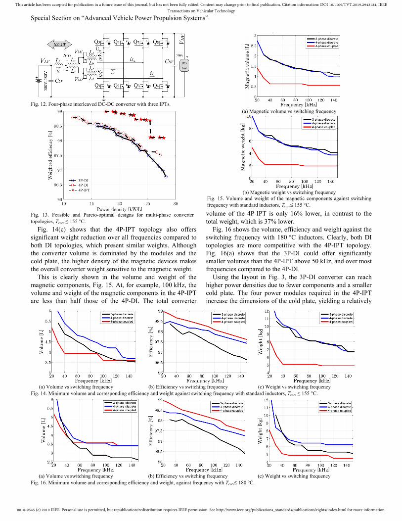
Fig. 13 shows the feasible Pareto-optimal designs for the three topologies in terms average full-load efficiency vs. power density with standard 155 °C inductors. The most obvious finding is that the three topologies achieve similar maximum power densities: 28.2 kW/L for the 3P-DI, 27.2 kW/L for the 4P-DI, and 27.8 kW/L for the 4P-IPT.
The plots in Fig. 14 compare the volume, efficiency and weight against the increase in switching frequency. The 4P-IPT shows a reducing size of the magnetic components before reaching its most power-dense design at 100 kHz, Fig. 14(a), beyond which the size of the IPTs cannot be further reduced. In contrast, the power-density of both DI topologies increases with frequency up to 140 kHz. Apparently, the 4P-IPT offers a lower volume than both DI topologies at almost any frequency, whilst the 4P-DI yields the highest volume.
Fig. 14(b) shows that the efficiency of the 4P-IPT is also superior. The semiconductor losses in the 4P-DI and 4P-IPT are very similar at each frequency; the difference in efficiency is driven by the magnetic losses. The major drop in efficiency of the 3P-DI is due to higher semiconductor losses.
Fig. 11. Weighted efficiency and power density of the prototype converter and the theoretical Pareto-front.
(a)
(b)
Fig. 10. Experimental waveforms of the converter, (a) Buck mode, 38.4 kW, VLV= 311 V, VHV= 500 V, IL= 120 A, D= 0.636. (b) Boost mode, 60.8 kW, VLV= 380 V, VHV= 752 V, IL= 160 A, D= 0.495.
0018-9545 (c) 2019 IEEE. Personal use is permitted, but republication/redistribution requires IEEE permission. See http://www.ieee.org/publications_standards/publications/rights/index.html for more information.
This article has been accepted for publication in a future issue of this journal, but has not been fully edited. Content may change prior to final publication. Citation information: DOI 10.1109/TVT.2019.2943124, IEEETransactions on Vehicular Technology
Special Section on “Advanced Vehicle Power Propulsion Systems”
Fig. 14(c) shows that the 4P-IPT topology also offers significant weight reduction over all frequencies compared to both DI topologies, which present similar weights. Although the converter volume is dominated by the modules and the cold plate, the higher density of the magnetic devices makes the overall converter weight sensitive to the magnetic weight.
This is clearly shown in the volume and weight of the magnetic components, Fig. 15. At, for example, 100 kHz, the volume and weight of the magnetic components in the 4P-IPT are less than half those of the 4P-DI. The total converter
volume of the 4P-IPT is only 16% lower, in contrast to the total weight, which is 37% lower.
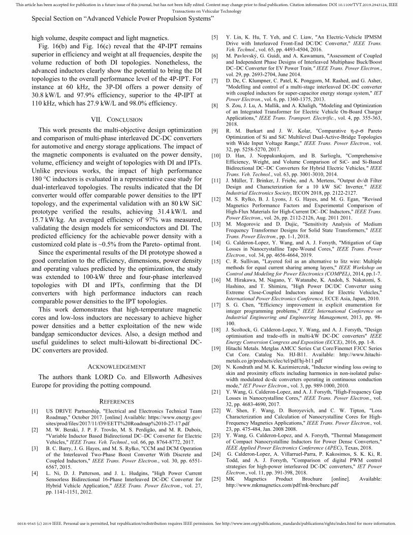
Fig. 16 shows the volume, efficiency and weight against the switching frequency with 180 °C inductors. Clearly, both DI topologies are more competitive with the 4P-IPT topology. Fig. 16(a) shows that the 3P-DI could offer significantly smaller volumes than the 4P-IPT above 50 kHz, and over most frequencies compared to the 4P-DI.
Using the layout in Fig. 3, the 3P-DI converter can reach higher power densities due to fewer components and a smaller cold plate. The four power modules required in the 4P-IPT increase the dimensions of the cold plate, yielding a relatively
(a) Volume vs switching frequency (b) Efficiency vs switching frequency (c) Weight vs switching frequency
Fig. 16. Minimum volume and corresponding efficiency and weight, against frequency with Tcore 180 C.
(a) Magnetic volume vs switching frequency
(b) Magnetic weight vs switching frequency
Fig. 15. Volume and weight of the magnetic components against switching frequency with standard inductors, Tcore 155 C.
(a) Volume vs switching frequency (b) Efficiency vs switching frequency (c) Weight vs switching frequency
Fig. 14. Minimum volume and corresponding efficiency and weight against switching frequency with standard inductors, Tcore ≤ 155 C.
Fig. 12. Four-phase interleaved DC-DC converter with three IPTs.
Fig. 13. Feasible and Pareto-optimal designs for multi-phase convertertopologies, Tcore ≤ 155 C.
0018-9545 (c) 2019 IEEE. Personal use is permitted, but republication/redistribution requires IEEE permission. See http://www.ieee.org/publications_standards/publications/rights/index.html for more information.
This article has been accepted for publication in a future issue of this journal, but has not been fully edited. Content may change prior to final publication. Citation information: DOI 10.1109/TVT.2019.2943124, IEEETransactions on Vehicular Technology
Special Section on “Advanced Vehicle Power Propulsion Systems”
high volume, despite compact and light magnetics. Fig. 16(b) and Fig. 16(c) reveal that the 4P-IPT remains
superior in efficiency and weight at all frequencies, despite the volume reduction of both DI topologies. Nonetheless, the advanced inductors clearly show the potential to bring the DI topologies to the overall performance level of the 4P-IPT. For instance at 60 kHz, the 3P-DI offers a power density of 30.8 kW/L and 97.9% efficiency, superior to the 4P-IPT at 110 kHz, which has 27.9 kW/L and 98.0% efficiency.
VII. CONCLUSION
This work presents the multi-objective design optimization and comparison of multi-phase interleaved DC-DC converters for automotive and energy storage applications. The impact of the magnetic components is evaluated on the power density, volume, efficiency and weight of topologies with DI and IPTs. Unlike previous works, the impact of high performance 180 °C inductors is evaluated in a representative case study for dual-interleaved topologies. The results indicated that the DI converter would offer comparable power densities to the IPT topology, and the experimental validation with an 80 kW SiC prototype verified the results, achieving 31.4 kW/L and 15.7 kW/kg. An averaged efficiency of 97% was measured, validating the design models for semiconductors and DI. The predicted efficiency for the achievable power density with a customized cold plate is ~0.5% from the Pareto- optimal front.
Since the experimental results of the DI prototype showed a good correlation to the efficiency, dimensions, power density and operating values predicted by the optimization, the study was extended to 100-kW three and four-phase interleaved topologies with DI and IPTs, confirming that the DI converters with high performance inductors can reach comparable power densities to the IPT topologies.
This work demonstrates that high-temperature magnetic cores and low-loss inductors are necessary to achieve higher power densities and a better exploitation of the new wide bandgap semiconductor devices. Also, a design method and useful guidelines to select multi-kilowatt bi-directional DC-DC converters are provided.
ACKNOWLEDGEMENT
The authors thank LORD Co. and Ellsworth Adhesives Europe for providing the potting compound.
REFERENCES [1] US DRIVE Partnership, "Electrical and Electronics Technical Team
Roadmap," October 2017. [online] Available: https://www.energy.gov/ sites/prod/files/2017/11/f39/EETT%20Roadmap%2010-27-17.pdf
[2] M. W. Beraki, J. P. F. Trovão, M. S. Perdigão, and M. R. Dubois, "Variable Inductor Based Bidirectional DC–DC Converter for Electric Vehicles," IEEE Trans. Veh. Technol., vol. 66, pp. 8764-8772, 2017.
[3] B. C. Barry, J. G. Hayes, and M. S. Ryłko, "CCM and DCM Operation of the Interleaved Two-Phase Boost Converter With Discrete and Coupled Inductors," IEEE Trans. Power Electron., vol. 30, pp. 6551-6567, 2015.
[4] L. Ni, D. J. Patterson, and J. L. Hudgins, "High Power Current Sensorless Bidirectional 16-Phase Interleaved DC-DC Converter for Hybrid Vehicle Application," IEEE Trans. Power Electron., vol. 27, pp. 1141-1151, 2012.
[5] Y. Lin, K. Hu, T. Yeh, and C. Liaw, "An Electric-Vehicle IPMSM Drive with Interleaved Front-End DC/DC Converter," IEEE Trans. Veh. Technol., vol. 65, pp. 4493-4504, 2016.
[6] M. Pavlovský, G. Guidi, and A. Kawamura, "Assessment of Coupled and Independent Phase Designs of Interleaved Multiphase Buck/Boost DC–DC Converter for EV Power Train," IEEE Trans. Power Electron., vol. 29, pp. 2693-2704, June 2014.
[7] D. De, C. Klumpner, C. Patel, K. Ponggorn, M. Rashed, and G. Asher, "Modelling and control of a multi-stage interleaved DC-DC converter with coupled inductors for super-capacitor energy storage system," IET Power Electron., vol. 6, pp. 1360-1375, 2013.
[8] S. Zou, J. Lu, A. Mallik, and A. Khaligh, "Modeling and Optimization of an Integrated Transformer for Electric Vehicle On-Board Charger Applications," IEEE Trans. Transport. Electrific., vol. 4, pp. 355-363, 2018.
[9] R. M. Burkart and J. W. Kolar, "Comparative -- Pareto Optimization of Si and SiC Multilevel Dual-Active-Bridge Topologies with Wide Input Voltage Range," IEEE Trans. Power Electron., vol. 32, pp. 5258-5270, 2017.
[10] D. Han, J. Noppakunkajorn, and B. Sarlioglu, "Comprehensive Efficiency, Weight, and Volume Comparison of SiC- and Si-Based Bidirectional DC–DC Converters for Hybrid Electric Vehicles," IEEE Trans. Veh. Technol., vol. 63, pp. 3001-3010, 2014.
[11] J. Müller, T. Brinker, J. Friebe, and A. Mertens, "Output dv/dt Filter Design and Characterization for a 10 kW SiC Inverter," IEEE Industrial Electronics Society, IECON 2018, pp. 2122-2127.
[12] M. S. Rylko, B. J. Lyons, J. G. Hayes, and M. G. Egan, "Revised Magnetics Performance Factors and Experimental Comparison of High-Flux Materials for High-Current DC–DC Inductors," IEEE Trans. Power Electron., vol. 26, pp. 2112-2126, Aug. 2011 2011.
[13] M. Mogorovic and D. Dujic, "Sensitivity Analysis of Medium Frequency Transformer Designs for Solid State Transformers," IEEE Trans. Power Electron., pp. 1-1, 2018.
[14] G. Calderon-Lopez, Y. Wang, and A. J. Forsyth, "Mitigation of Gap Losses in Nanocrystalline Tape-Wound Cores," IEEE Trans. Power Electron., vol. 34, pp. 4656-4664, 2019.
[15] C. R. Sullivan, "Layered foil as an alternative to litz wire: Multiple methods for equal current sharing among layers," IEEE Workshop on Control and Modeling for Power Electronics (COMPEL), 2014, pp.1-7.
[16] M. Hirakawa, M. Nagano, Y. Watanabe, K. Andoh, S. Nakatomi, S. Hashino, and T. Shimizu, "High Power DC/DC Converter using Extreme Close-Coupled Inductors aimed for Electric Vehicles," International Power Electronics Conference, ECCE Asia, Japan, 2010.
[17] S. G. Chen, "Efficiency improvement in explicit enumeration for integer programming problems," IEEE International Conference on Industrial Engineering and Engineering Management, 2013, pp. 98-100.
[18] J. Scoltock, G. Calderon-Lopez, Y. Wang, and A. J. Forsyth, "Design optimisation and trade-offs in multi-kW DC-DC converters" IEEE Energy Conversion Congress and Exposition (ECCE), 2016, pp. 1-8.
[19] Hitachi Metals. Metglas AMCC Series Cut Core/Finemet F3CC Series Cut Core. Catalog No. HJ-B11. Available: http://www.hitachi-metals.co.jp/products/elec/tel/pdf/hj-b11.pdf
[20] N. Kondrath and M. K. Kazimierczuk, "Inductor winding loss owing to skin and proximity effects including harmonics in non-isolated pulse-width modulated dc-dc converters operating in continuous conduction mode," IET Power Electron., vol. 3, pp. 989-1000, 2010.
[21] Y. Wang, G. Calderon-Lopez, and A. J. Forsyth, "High-Frequency Gap Losses in Nanocrystalline Cores," IEEE Trans. Power Electron., vol. 32, pp. 4683-4690, 2017.
[22] W. Shen, F. Wang, D. Boroyevich, and C. W. Tipton, "Loss Characterization and Calculation of Nanocrystalline Cores for High-Frequency Magnetics Applications," IEEE Trans. Power Electron., vol. 23, pp. 475-484, Jan. 2008 2008.
[23] Y. Wang, G. Calderon-Lopez, and A. Forsyth, "Thermal Management of Compact Nanocrystalline Inductors for Power Dense Converters," IEEE Applied Power Electronics Conference (APEC), Texas, 2018.
[24] G. Calderon-Lopez, A. Villarruel-Parra, P. Kakosimos, S. K. Ki, R. Todd, and A. J. Forsyth, "Comparison of digital PWM control strategies for high-power interleaved DC-DC converters," IET Power Electron., vol. 11, pp. 391-398, 2018.
[25] MK Magnetics Product Brochure [online]. Available: http://www.mkmagnetics.com/pdf/mk-brochure.pdf

0018-9545 (c) 2019 IEEE. Personal use is permitted, but republication/redistribution requires IEEE permission. See http://www.ieee.org/publications_standards/publications/rights/index.html for more information.
This article has been accepted for publication in a future issue of this journal, but has not been fully edited. Content may change prior to final publication. Citation information: DOI 10.1109/TVT.2019.2943124, IEEETransactions on Vehicular Technology
Special Section on “Advanced Vehicle Power Propulsion Systems”
[26] LORD Corporation. CoolThermTM SC-320 Thermally Conductive Silicone Encapsulant [Online]. Available: https://lordfulfillment.com/ pdf/44/DS3724_CoolThermSC-320.pdf
[27] N. Simpson and P. H. Mellor, "Additive manufacturing of shaped profile windings for minimal AC loss in gapped inductors," IEEE Intl. Electric Machines and Drives Conference (IEMDC), 2017, pp. 1-7.
Gerardo Calderon-Lopez received the degree of ing. en comunicaciones y electrónica from the National Polytechnic Institute (IPN), Mexico City in 1999, the M.Sc. in power electronics and drives from The Universities of Birmingham and Nottingham, U.K. in 2001, and the Ph. D. degree in power electronics from The
University of Manchester, U.K. in 2009. He is a Research Associate at The University of
Manchester. His research interests include power-dense converters and magnetic components.
James Scoltock (S’09–M’15) received the B.E. (Hons) and Ph.D. degrees, both in electrical and electronic engineering, from the University of Auckland, New Zealand, in 2009 and 2015, respectively. He was a Research Associate in the School of Electrical and Electronic Engineering, the University of
Manchester, U.K., from 2015 until 2017. He is currently a Research Associate in the Department of Electronic and Electrical Engineering, the University of Sheffield, U.K. His research interests include power electronics, electrical drives, model predictive control, and energy storage and management.
Yiren Wang received the B.Eng.(Hons.) degree in electrical and electronic engineering from The University of Manchester, Manchester, U.K. and North China Electric Power University, Baoding, China, in 2011, and the Ph.D. degree in power electronics from The University of Manchester, U.K., in 2015.
She was a Research Associate at The University of Manchester from 2016 to 2018. She is currently a Power Electronic Design Engineer at Zytek Automotive/Continental Engineering Services, U.K. Her research interests include magnetic components for high power density DC-DC converters, modeling, design and optimisation.
Ian Laird (S'09-M'11) received both the B.Eng. degree (Hons.I) in mechatronic engineering in 2008 and the PhD degree in electrical engineering (power electronics) in 2013 from the University of Sydney, NSW, Australia. From 2008 to 2009 he worked at the CSIRO material science and engineering division in
Lindfield, NSW, Australia in the thermoelectric energy group. From 2014 to 2019 he worked as a research associate in the
Electrical Energy Management Group (EEMG) at the University of Bristol. Currently he is a lecturer in the department of Electrical and Electronic Engineering at the University of Bristol. His research interests include thermoelectrics, converter topologies, wide band-gap devices and design optimization.
Xibo Yuan (S'09-M'11-SM'15) received the B.S. degree from China University of Mining and Technology, Xuzhou, China, and the Ph.D. degree from Tsinghua University, Beijing, China, in 2005 and 2010, respectively, both in electrical engineering.
He has been a Professor since 2017 in the Electrical Energy Management Group, Department of Electrical and Electronic Engineering, University of Bristol, Bristol, U.K. He also holds the Royal Academy of Engineering/Safran Chair in Advanced Aircraft Power Generation Systems.
His research interests include power electronics and motor drives, wind power generation, multilevel converters, application of wide-bandgap devices, electric vehicles and more electric aircraft technologies.
Andrew J. Forsyth (M’98) received the B.Sc.(Eng) degree in electrical engineering from Imperial College, London, U.K., in 1981 and the Ph.D. degree in power electronics from the University of Cambridge, Cambridge, U.K., in 1987.
He was a Design Engineer with GEC Electrical Projects Ltd from 1981 to 1983,
a Lecturer at the University of Bath from 1986-1990, and a Lecturer / Senior Lecturer at Birmingham University from 1991 to 2004. Since 2004 he has been Professor of Power Electronics at the University of Manchester, Manchester U.K. His research interests include high-frequency converters and magnetic components, converter modelling and control, aerospace and electric vehicle applications.