Embed Size (px)
Citation preview

Martin 16 Power-Assist System – Mk IV Self-contained, portable, power-assisted steering and sail sheeting system
Operator Manual

Martin 16 Power-Assist System – Mk IV Self-contained, portable, power-assisted steering and sail sheeting system
06/03/13 Operator Manual – Mk IV 1
Congratulations! The vision of the Martin 16 Power-Assist System is to get everyone out sailing. Men, women and children with significant disabilities use a Power-Assist System like yours to enjoy the freedom of independent sailing, by providing power-assisted steering and sheeting for the Martin 16 sloop, through a familiar joystick or sip & puff interface
Everything that you need to know about how to install, operate and care for your Power-Assist System is in this Operator Manual. If it’s not – give me a call!
Fair Sailing! Steve Alvey 403-870-7210
Warning to Operator The Martin 16 Power-Assist System is an ASSISTIVE DEVICE, intended to assist sailors with limited hand function to operate sailboats independently. INVENTURE MANAGEMENT LIMITED provides no specific warranties or claims of the Martin 16 Power-Assist System’s "fitness for use" for any person, on any particular vessel or sailing conditions. Sailing is a dangerous sport and the operator uses the Martin 16 Power-Assist System at his/her own risk. Operators are responsible for receiving proper training in the use of the Martin 16 Power-Assist System and for taking normal and appropriate precautions while using the system. Always have able-bodied persons on board your vessel so that, in conditions of inclement weather or when emergency maneuvers are required, they may disengage the Martin 16 Power-Assist System and steer the boat manually. In the event that the Martin 16 Power-Assist System malfunctions for any reason while sailing, always be prepared to revert to manual steering control.

Martin 16 Power-Assist System – Mk IV Self-contained, portable, power-assisted steering and sail sheeting system
06/03/13 Operator Manual – Mk IV 2
Table of Contents Martin 16 Power-Assist System A Brief History ......................................................................................................... 3 Joystick Module ...................................................................................................... 4 Sip & Puff Module ................................................................................................... 5 Windlass ................................................................................................................. 6 Battery Module / Intelligent Battery Charger .......................................................... 7 Other Optional Equipment .................................................................................. 7, 8 Power-Assist System Features & Operation Joystick Module ...................................................................................................... 9 Connectors ................................................................................................ 9 Power ....................................................................................................... 10 Indicator LEDs ......................................................................................... 10 Battery Meter ........................................................................................... 10 Audio BEEPs ........................................................................................... 10 Joystick .................................................................................................... 11 Wireless Remote Control ......................................................................... 11 Sip & Puff Module ................................................................................................ 12 Connectors .............................................................................................. 12 Power ....................................................................................................... 12 Pneumatic Connections ........................................................................... 13 Wireless Remote Control ......................................................................... 13 Wireless Remote Control (option at time of order) ............................................... 14 When you first receive your Power-Assist System System Test components on land ........................................................................ 15 Installing the Power-Assist System on a Martin 16 for the first time Install the Pedestal (Part # D030) ........................................................................ 18 Install the Tiller Cross Arm and Tiller Rod ............................................................ 19 Adjusting the length of the Tiller Rod ................................................................... 21 Installing the Sip&Puff Module (optional) ............................................................. 22 Installing the Bilge pump (optional) ...................................................................... 23 Installing the Power-Assist System each time you go sailing Install the Windlass: ............................................................................................. 24 Install the Power-Assist Joystick Module: ............................................................ 25 Install the Tiller Cross Arm and Tiller Rod ............................................................ 25 Install the Helm Drive Motor ................................................................................. 26 Donning the Upper Body Support Harness .......................................................... 27 Before you go sailing Adjust the JIB SLOT TRIM sheet ......................................................................... 28 Check (manual) Joystick is Centered ................................................................... 29 Check Tiller Rod is Centered ................................................................................ 29 Check Sip&Puff Module operation ....................................................................... 29 Check Wireless Remote Control operation .......................................................... 29 Check Electric Bilge Pump operation ................................................................... 29 Caution while sailing ........................................................................................ 30 Caring for your Martin 16 Power-Assist System ............................................ 32 Charging the battery ............................................................................................. 33 Warranty ............................................................................................................... 34 Appendix A: Spare /`Replacement parts ............................................................. 35

Martin 16 Power-Assist System – Mk IV Self-contained, portable, power-assisted steering and sail sheeting system
06/03/13 Operator Manual – Mk IV 3
M16 Power-Assist System – a Brief History The idea for sip & puff controls for a sailboat came from Sam Sullivan, a quadriplegic and founder of the Disabled Sailing Association. Sam had seen high-quads operate their wheelchairs by sip & puff, and envisioned that this technology might be used to control a sailboat. The world’s first sip & puff control system for a sailboat was designed by the Neil Squires Foundation (Vancouver, Canada) and installed on a Sunbird sloop the “Royal Spirit”. The Royal Spirit debuted at the Mobility Cup regatta in 1994.
The sip& puff technology was refined and adapted to the new Martin 16 sloop in 1998 under the “Royal Bank Project”. The Disabled Sailing Association of Alberta with the financial support of Royal Bank Financial Group managed this project. Steve Alvey brought a volunteer Project Team together, several companies donated parts and equipment, and a robust, self-contained system was designed and hand-manufactured to meet the needs of high-quad sailors. Steve Alvey and Mark Isaak continued development of the system in 1999 and advanced the design, functionality and reliability, culminating in the current Mark IV System.
Martin 16 Power-Assist Systems are in service at DSA programs in Canada, USA, UK, Japan, Greece, Australia and Puerto Rico. At Mobility Cup, Canada’s International Regatta for Sailors with Disabilities, more than 15 high-level quad sailors use Power-
Assist Systems to compete on the same starting line with 45 other sailors. The Power-Assist System has changed the lives of these sailors, and more like them each new season. Each year, we refine the function and capability of the system, through feedback from sailors. Please provide us with your feedback and help us make the Martin 16 Power-Assist System even better.

Martin 16 Power-Assist System – Mk IV Self-contained, portable, power-assisted steering and sail sheeting system
06/03/13 Operator Manual – Mk IV 4
M16 Power-Assist Joystick Module Self-contained, portable, weatherproof system components are intended for outdoor use in marine environment. The Power-Assist System can be installed in minutes on any standard Martin 16 sloop, or any other tiller-steered sloop (Freedom 20, Sonar, Catalina 22, etc.). Power-Assist Joystick
Module contains the main control computer and a joystick control in a weatherproof enclosure. The Joystick Module is light and can be
positioned comfortably beside the sailor – to the left or right – or on the sailor’s lap if necessary. Built-in "armrest" provides support for the sailor's arm for familiar wheelchair-like operation.
L.E.D. battery meter provides battery state
indicator before and during your sailing session
Any 12V power source can provide power to the Joystick Module: 1) the portable Power-Assist Battery Module or 2) a “house battery” on boats equipped with 12V DC power.
Emergency Disengage of the drive motor in the case of system malfunction is provided via a “quick-release” pin that can be operated from the rear seat of the Martin 16. (Note: Emergency Disengage is NOT accessible to helmsperson).
Auxiliary motor control (option at the time of
order). The Mk IV Joystick Module will control up to three additional bi-directional DC motors, via the ““y” axis of the joystick. These auxiliary functions may be used to control the jib trim, boom vang, or outhaul, for example.
Wireless Remote Control (option) provides wireless
control of all functions of the Power-Assist System, using a convenient and compact “key fob” remote control (automotive style). The Remote Control may be used by a person sailing with a sip & puff sailor, or an Instructor in a motor boat.

Martin 16 Power-Assist System – Mk IV Self-contained, portable, power-assisted steering and sail sheeting system
06/03/13 Operator Manual – Mk IV 5
M16 Sip & Puff Module Sip & Puff Module provides a
sensitive pneumatic control interface, allowing high-quadriplegic sailors to control the Power-Assist System functions using their breath. The sip & puff interface is a chest-mounted control “stalk”. The stalk positions two pneumatic “straws” within reach of the sailor’s lips: one to control the HELM and one to control the WINDLASS.
Any 12V power source can provide power to the Sip &
Puff Module: 1) the portable Power-Assist Battery Module or 2) a “house battery” on boats equipped with 12V DC power.
Wireless Remote Control (option) povides control of all functions of the Power-Assist System, using a convenient and compact “key fob” remote control (automotive style). The Remote Control may be used, for example, by a person sailing with a sip & puff sailor, or an Instructor in a motor boat.
Martin 16 Power-Assist System – Mk IV Self-contained, portable, power-assisted steering and sail sheeting system
06/03/13 Operator Manual – Mk IV 6
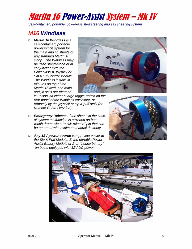
M16 Windlass Martin 16 Windlass is a
self-contained, portable power winch system for the main and jib sheets of any standard Martin 16 sloop. The Windlass may be used stand-alone or in conjunction with the Power-Assist Joystick or Sip&Puff Control Module. The Windlass installs in minutes on top of the Martin 16 keel, and main and jib sails are trimmed in unison via either a large toggle switch on the rear panel of the Windlass enclosure, or remotely by the joystick or sip & puff stalk (or Remote Control key fob).
Emergency Release of the sheets in the case
of system malfunction is provided on both winch drums via a “quick-release” pin that can be operated with minimum manual dexterity.
Any 12V power source can provide power to
the Sip & Puff Module: 1) the portable Power-Assist Battery Module or 2) a “house battery” on boats equipped with 12V DC power.

Martin 16 Power-Assist System – Mk IV Self-contained, portable, power-assisted steering and sail sheeting system
06/03/13 Operator Manual – Mk IV 7
M16 Power-Assist Battery Module Portable Battery Module houses a
13AH GEL-TYPE, “spill-proof” battery which provides from 5 - 8 hours sailing time before re-charging. The Battery Module may be used to power one or more of 1) Joystick Module, 2) Sip&Puff Module, 3) Windlass, and/or 4) Electric Bilge Pump. When not in use, a compact battery charger maintains the battery’s condition and ready for your next sailing session. (Note: APPROXIMATE battery life, as sailing conditions vary widely).
Intelligent Battery Charger is perfectly matched to the GEL-TYPE battery technology used in the Battery Module. This “global” multi-voltage charger 1) is compatible with any electric system in the world; 2) will charge battery to full capacity in less than three hours; 3) can be left on “charge” indefinitely, without risk of damage caused by over-charging the Battery Module, and 4) is UL, CSA and CE Approved. NOTE: common automotive or marine battery chargers are designed for larger, lead-acid type batteries, and can damage the Battery Module battery if left on charge for more than one hour.
M16 Adaptor Kit M16 Adaptor Kit provides necessary conversion
parts and instructions to make pre-1999 model Martin 16s accept the Power-Assist System. (Martin 16s manufactured after 1999 do not require this kit).
M16 Electric Bilge Pump Electric Bilge Pump provides automatic bilge pumping for sailors that cannot
operate the manual bilge pump. The Electric Bilge Pump is powered by the Battery Module.

Martin 16 Power-Assist System – Mk IV Self-contained, portable, power-assisted steering and sail sheeting system
06/03/13 Operator Manual – Mk IV 8
M16 Upper Body Support Harness The Upper Body Support Harness may be
worn by paraplegic, quadriplegic or hemiplegic sailors in weather and sea conditions where additional upper body support is required. The Upper Body Support Harness is made of robust webbing with industrial quick-release velcro fastenings. It can be adjusted to fit any sailor, and used on the Martin 16 as well as other adapted sailboats (and powerboats) wherever suitable anchor points can be arranged to each side of the sailor.

Martin 16 Power-Assist System – Mk IV Self-contained, portable, power-assisted steering and sail sheeting system
06/03/13 Operator Manual – Mk IV 9
M16 Power-Assist System Features & Operation Joystick Module CAUTION: ASSURE THAT ANYONE USING THE POWER-ASSIST SYSTEM IS ORIENTED IN ITS OPERATION AND CARE. We recommend that ONE PERSON be made responsible for your system’s care and maintenance. The Joystick Module contains the control computer, housed in a weatherproof container. The control computer is programmed to accept control inputs from the joystick and MODE buttons, and control the HELM DRIVE, WINDLASS and AUXILIARY MOTOR(S) (option).
Joystick Module - Connectors The Power-Assist Joystick Module has two water-resistant connectors on the rear panel of the enclosure. These connectors are labeled and keyed so that you cannot damage the Module by plugging them in to the incorrect connector.
Care of Connectors To assure reliable operation, IT IS IMPORTANT TO CARE FOR THESE CONNECTORS, to maintain their electrical integrity and to assure that no water enters the Power-Assist enclosure. Check that the weather-proof protective caps are snugly installed over un-used
Power-Assist Helm connectors at all times on and off the water. The Power cord connector has a KEY that allows it to fit only one way. Before
inserting the male plug, locate the KEY and align it with the connector KEY. Seat firmly and screw the retainer ring on until hand-tight.
Maintain connectors by cleaning them and spraying with a moisture displacement fluid (Boeing BOESHIELD T-9 is ideal. You can buy it at WEST MARINE).
Before you insert any male connector, check that it is free of water, dirt and/or sand. Clean it with fresh water if required and spray with BOESHIELD.
When transporting the system, be careful not to drag the cords and male connectors along the ground or through sand and dirt.
When seating 3-pin connectors, make sure that they seat firmly, and do not force the fit.
When removing 3-pin connectors, do not pull on the cords. Lift uniformly on entire connector housing.

Martin 16 Power-Assist System – Mk IV Self-contained, portable, power-assisted steering and sail sheeting system
06/03/13 Operator Manual – Mk IV 10
Joystick Module - Power The Joystick Module is powered up when you plug the power cord in – there is no power switch The Power cord connector has a KEY that allows it to fit only one way. Before inserting the male plug, locate the KEY and align it with the connector KEY. Seat firmly and screw the retainer ring on until hand-tight, so that power will not be accidentally switched off while sailing. The Joystick Module indicator LEDs and buzzer will
be tested during power-up, as the system initializes itself.
To turn the power OFF, you must disconnect the Joystick Module power cord.
Indicator LEDs Below the joystick are five light emitting diodes (LEDs). These LEDs indicate which functions the joystick will activate if deflected. Under normal circumstances, the HELM and WINCH LEDs will be lit.
Battery Meter Every ten seconds, the battery charge will be measured and the Battery Meter will indicate the level of charge in the battery. This is indicated by cycling the Indicator LEDS from left to right and then back again. Full charge is indicated by cycling all FIVE LEDS from left to right and back. Similarly, 80% = 4 LEDs; 60% = 3 LEDs; 40% = 2 LEDs; 20% = 1 LED. A critically low battery voltage level (less than 10.5V) is indicated by constantly flashing LED and a continuous BEEEEEP tone from the buzzer. Once the battery meter has cycled, the Indicator LEDs return to indicate the active functions (i.e. HELM and WINCH).
Audio BEEPs In addition to the LED indicators, an audio “BEEP” confirms the operation of the Joystick or pressing a button.
Martin 16 Power-Assist System – Mk IV Self-contained, portable, power-assisted steering and sail sheeting system
06/03/13 Operator Manual – Mk IV 11
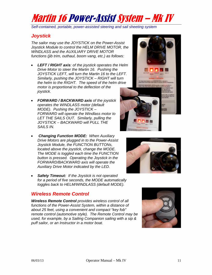
Joystick The sailor may use the JOYSTICK on the Power-Assist Joystick Module to control the HELM DRIVE MOTOR, the WINDLASS and the AUXILIARY DRIVE MOTOR functions (jib trim, outhaul, boom vang, etc.) as follows: LEFT / RIGHT axis: of the joystick operates the Helm
Drive Motor to steer the Martin 16. Pushing the JOYSTICK LEFT, will turn the Martin 16 to the LEFT. Similarly, pushing the JOYSTICK – RIGHT will turn the helm to the RIGHT. The speed of the helm drive motor is proportional to the deflection of the joystick.
FORWARD / BACKWARD axis of the joystick
operates the WINDLASS motor (default MODE). Pushing the JOYSTICK – FORWARD will operate the Windlass motor to LET THE SAILS OUT. Similarly, pulling the JOYSTICK – BACKWARD will PULL THE SAILS IN.
Changing Function MODE: When Auxiliary
Drive Motors are plugged in to the Power-Assist Joystick Module, the FUNCTION BUTTONs, located above the joystick, change the MODE. The MODE is toggled each time the FUNCTION button is pressed. Operating the Joystick in the FORWARD/BACKWARD axis will operate the Auxiliary Drive Motor indicated by the LED.
Safety Timeout: If the Joystick is not operated
for a period of five seconds, the MODE automatically toggles back to HELM/WINDLASS (default MODE).
Wireless Remote Control Wireless Remote Control provides wireless control of all functions of the Power-Assist System, within a distance of about 25 feet, using a convenient and compact “key fob” remote control (automotive style). The Remote Control may be used, for example, by a Sailing Companion sailing with a sip & puff sailor, or an Instructor in a motor boat.

Martin 16 Power-Assist System – Mk IV Self-contained, portable, power-assisted steering and sail sheeting system
06/03/13 Operator Manual – Mk IV 12
Sip & Puff Module The Sip & Puff Module provides a pneumatic control interface, allowing high-quadriplegic sailors to control the Power-Assist System functions using their breath. The Sip & Puff Module interface is a chest-mounted control “stalk”. The stalk positions two pneumatic “straws” within reach of the sailor’s lips: one to control the HELM and one to control the WINDLASS.
Sip & Puff Module - Connectors The Sip & Puff Module has a water-resistant connector on the rear panel of the enclosure to connect the HELM DRIVE.
Sip & Puff Module - Power The Sip & Puff Module is powered up when you plug the power cord in – there is no power switch. The Power cord connector has a KEY that allows it to fit only one way. Before inserting the male plug, locate the KEY and align it with the connector KEY. Seat firmly and screw the retainer ring on until hand-tight, so that power will not be accidentally switched off while sailing.

Martin 16 Power-Assist System – Mk IV Self-contained, portable, power-assisted steering and sail sheeting system
06/03/13 Operator Manual – Mk IV 13
Sip & Puff Module – Pneumatic Connections The pneumatic tubes on the Sip & Puff Chest Stalk have to be connected to the tubes on the Sip & Puff module. Once connected, they can be left connected as convenient for the sailor. Here’s how you connect the tubes:
The lengths of the two tubes for the Sip&Puff stalk are “keyed” to fit the Sip&Puff Module. (i.e. WHITE is shorter than BLACK tube connector)
Gently press the LUER fitting on the end of the tubing directly into the 1/8” tubing on the Sip&Puff Module. Work this fitting into the tube snuggly. Make certain that the connection is air-tight. Then hand tighten the knurled nut on the LUER fitting (BLACK and WHITE nuts). When seated properly, these nuts will grab the tubing when and tighten.
Wireless Remote Control Wireless Remote Control provides wireless control of all functions of the Power-Assist System, within a distance of about 25 feet, using a convenient and compact “key fob” remote control (automotive style). The Remote Control may be used, for example, by a Sailing Companion sailing with a sip & puff sailor, or an Instructor in a motor boat.
CAUTION: Sip & Puff module is recommended for “personal use” only: The components of the Sip & Puff Module come in contact with the user’s mouth, breath, saliva and other body fluids. Since disease can be transferred through body fluids, medical practice recommends that the Sip & Puff Stalk and the Sip & Puff Module be reserved for personal use (i.e. one Stalk/Module for each user). The user of the Sip & Puff stalk should always clean the stalk parts with denatured alcohol prior to use. Inspect the tubing for trapped moisture or saliva and disassemble and clean as required. The Operator is responsible for appropriate use of the Sip & Puff module components and the associated medical risks.

Martin 16 Power-Assist System – Mk IV Self-contained, portable, power-assisted steering and sail sheeting system
06/03/13 Operator Manual – Mk IV 14
Wireless Remote Control (option at time of order) As a safety feature, another person can control the Power-Assist Joystick Module or the Sip & Puff Module remotely, by pressing the buttons on a convenient wireless “key fob” control (automotive style). There are four buttons on the key fob: LEFT/RIGHT control the HELM DRIVE and UP/DOWN control the WINDLASS (out/in). In typical conditions, the Remote Control will work within a 25 foot radius of the Joystick or Sip&Puff Module. Your key fob will be coded to work only with the Module that you ordered it with. A sticker with a number on it (i.e. “4” or “27”) will identify the code for your key fob. You need to tell us this number when ordering a spare or replacement key fob. CAUTION: The key fob is convenient, but not waterproof. If it is raining or wet while sailing, keep the key fob dry! You may order spare/replacement key fobs any time. CAUTION: THE WIRELESS REMOTE CONTROL IS PROVIDED AS A CONVENIENT REMOTE CONTROL OPTION. OPERATION IS SUBJECT TO BATTERY CONDITION, RADIO INTERFERENCE AND WEATHER CONDITIONS, SO IT IS NOT GUARANTEED TO OPERATE RELIABLY.

Martin 16 Power-Assist System – Mk IV Self-contained, portable, power-assisted steering and sail sheeting system
06/03/13 Operator Manual – Mk IV 15
When you first receive your Power-Assist System… Your Power-Assist System and the optional accessories that you ordered have been system tested before being shipped to you. To familiarize yourself with the system, when you first receive your Martin 16 Power-Assist System:
Verify the System components against the packing slip enclosed with your system. Each component has your serial number and a part number on it.
Check for shipping damage Become familiar with and then connect all of the components and perform the
following System Tests on land. Problems? Call Steve Alvey at 403-870-7210
System Test components (on land)
If you have not already done so, take the time to read the System Features and Operation sections of this Manual. Gather the components of your Power-Assist System and place them on a clean surface. Place the Windlass on a soft towel for system tests. This will stop the winch drums from getting scuffed during testing. Identify the Power-Assist Connectors on each of the Battery Module, Joystick Module, Sip&Puff Module, Windlass, and Helm Drive. They are labeled and keyed to avoid mis-connection. See if you can connect the system components together… NOTE: if you have a Joystick Module and a Sip & Puff Module, you can only connect one of these to control the WINDLASS and HELM DRIVE at one time.
Identify and connect System Modules: 1. Windlass power cable to the Windlass connector
on the Battery Module NOTE: Connector is keyed
2. Helm Drive motor to HELM DRIVE connector on JOYSTICK MODULE (or SIP & PUFF MODULE)
3. Connect the Sip&Puff stalk tubing to the Sip&Puff Module:
4. Bilge Pump (option) to Bilge Pump connector on the Battery Module

Martin 16 Power-Assist System – Mk IV Self-contained, portable, power-assisted steering and sail sheeting system
06/03/13 Operator Manual – Mk IV 16
Connect to Power Connect the power cord to the Battery Module and fasten the retainer ring. . The Indicator LEDs will flash “on” as the system
initializes itself. Check the Battery Level Meter to assure that the battery is fully charged. After about ten seconds, all FIVE LEDS should cycle from left to right and then back again. If necessary, disconnect the power cord and charge the Battery Nodule.
Every ten seconds, the Battery Level Meter will
cycle, indicating the battery condition. Once you have a WINDLASS connected, the
Windlass Lamp will flash ON and OFF to indicate that the main computer is functioning correctly.
Test Joystick operation Operate the JOYSTICK on the Power-Assist Joystick Module: LEFT / RIGHT axis of the joystick operates the Helm Drive Motor to steer the Martin
16. Pushing the JOYSTICK LEFT, will turn the Martin 16 to the LEFT (HELM DRIVE extends). Similarly, pushing the JOYSTICK – RIGHT will turn the helm to the RIGHT (HELM DRIVE retracts).
FORWARD / BACKWARD axis of the joystick operates the WINDLASS motor
(default MODE). Pushing the JOYSTICK – FORWARD will operate the Windlass motor to LET THE SAILS OUT. Similarly, pulling the JOYSTICK – BACKWARD will PULL THE SAILS IN.
Test Sip & Puff operation (option) CAUTION: CLEAN THE SIP & PUFF STALK WITH ALCOHOL BEFORE AND AFTER USE. Connect the power cord to the Battery Module, and operate the SIP & PUFF Module functions as follows: HELM LEFT / RIGHT: Operate the Helm Drive motor by gently sipping and puffing
on the Sip & Puff stalk. The Helm Drive motor should respond promptly to the pressure of your breath. SIPPING retracts the Helm Drive motor. PUFFING extends the Helm Drive motor.
WINDLASS IN / OUT: To change to WINDLASS Mode, using your lips, gently “bite”
the nipple surrounding the Sip & Puff stalk, and release it. The Power-Assist System will “beep” once, and the HEARTBEAT LAMP will now flash on-and-off indicating WINDLASS Mode. Operate the WINDLASS motor by gently sipping and puffing on the Sip & Puff stalk. SIPPING will operate the Windlass motor to PULL THE SAILS IN. Similarly, PUFFING will LET THE SAILS OUT. The motor should respond promptly to the pressure of your breath.

Martin 16 Power-Assist System – Mk IV Self-contained, portable, power-assisted steering and sail sheeting system
06/03/13 Operator Manual – Mk IV 17
Test Bilge Pump operation (optional) Plug power cord into Battery Module. Then test the float switch operation as follows: Pick up the bilge pump and turn it “upside-down” to activate the float switch. The bilge pump should operate when up-side down, and turn off when right-side up. Test Wireless Remote Control (option) If you have a Wireless Remote Control with either a Joystick or Sip & Puff Control Module, test the four buttons and become familiar with the logical orientation of the key fob (i.e. so that LEFT BUTTON turns helm to the LEFT). The Wireless Remote Control will operate in a radius of about 25 feet from the Power-Assist Control Module, but is subject to shielding and interference. CAUTION: THE WIRELESS REMOTE CONTROL IS PROVIDED AS A CONVENIENT REMOTE CONTROL OPTION. OPERATION IS SUBJECT TO BATTERY CONDITION, RADIO INTERFERENCE AND WEATHER CONDITIONS, SO IT IS NOT GUARANTEED TO OPERATE RELIABLY. If any of the system components do not work as described, call Steve Alvey 403-870-7210.

Martin 16 Power-Assist System – Mk IV Self-contained, portable, power-assisted steering and sail sheeting system
06/03/13 Operator Manual – Mk IV 18
Installing the Power-Assist System on a Martin 16 for the first time… When you first get the system, you have to: (one time)
Install the Pedestal Socket Mount on your Martin 16 Install the Tiller Cross Arm and Tiller Rod on the Martin 16 rudder head Test the stop-to-stop operation of the Helm drive, and adjust as necessary to
center. Install the Pedestal Socket Mount (Raymarine Part # D030) 1. Identify the Pedestal Socket Mount (D030 on package). You’ll also need:
3/8” portable drill and ¼” bit 7/16” open-end wrench (small one) Large slot screwdriver Small tube of Sikaflex SEA-L or 241 Marine sealant or equivalent good
quality marine sealant, (NOT silicon caulking) 2. Locate the 6” hatch to the right of the helm seat.
Remove the hatch cover. Reach inside the cover and feel the “inner” construction of the cockpit just aft of the “scupper” in the ledge directly to the right of the seat back. You are going to install the pedestal on the ledge, just aft of the scupper.
3. Place the pedestal base plate on the ledge by
hand. It can be moved around, and you’re going to locate it about ¼” aft of the scupper, and ¼” from the edge of the lower cockpit wall (that runs down to the cockpit floor). You’re choosing a location that’s behind the scupper, but as far forward and to the left on the ledge as reasonable. Don’t locate it too close to these edges, as you have to install it with the backing plate inside the side tank. It will interfere with the inner walls if it’s too close to the edges. READ THIS INSTRUCTION AGAIN BEFORE DRILLING.
4. Hold the base plate firmly, and drill three ¼” holes, using the base plate as
your drilling guide. Ream the holes a bit to make the bolts fit freely. 5. Clean the cuttings away from the holes and put a thin bead of Sikaflex SEA-L
around each hole. Put the three ¼” bolts through the holes and then install the base plate on the ledge.

Martin 16 Power-Assist System – Mk IV Self-contained, portable, power-assisted steering and sail sheeting system
06/03/13 Operator Manual – Mk IV 19
6. Reach inside the hull with the aluminum backing plate and slide it over the
three bolts. This may take a little fiddling. If it won’t go on, your bolt holes may be crooked and may need to be reamed a bit more. Once on the three bolts, the backing plate should stay there by friction.
7. Place a lock washer and 7/16” nut on each bolt (supplied). You have to do
this by feel, so DON”T DROP THEM! Once you have tightened the nuts finger tight, place a 7/16” open-end wrench on each nut and tighten bolt with a large slot screwdriver. Don’t go bananas trying to over- tighten the bolts.
8. Thread the mount turret into the baseplate. Tighten snugly. Leave the
pedestal permanently in place.
Install the Tiller Cross Arm and Tiller Rod The ST 4000+ drive motor is connected to the Martin 16’s rudder head via the Tiller Rod and Tiller Cross Arm. These need to be installed once, and may or may not be left permanently in place. If you use the Power-Assist System EVERY TIME you go sailing, you may leave the Tiller Cross Arm and Tiller Rod installed. If you use the system only occasionally - for specific sailors that need it - I recommend that you install and remove the Tiller Cross Arm and Tiller Rod each time you use the system, and store with the Power-Assist System System components. Remove the 3/16” split pin from the Martin 16 rudder
head and then slide the Tiller Cross Arm over top of the rudder head from the back, forward. For proper control, it is important that the Tiller Cross Arm fit snuggly onto the rudder head. If it does not, it can be removed and gently squeezed in a metal vice to make it fit more snuggly. . NOTE: THERE ARE TWO DIFFERENT TYPES OF MARTIN 16 RUDDER HEAD FITTINGS THAT VARY SLIGHTLY IN SIZE. IF YOUR TILLER CROSS ARM DOES NOT SEEM TO FIT AT ALL, YOU MAY HAVE THE WRONG PART FOR YOUR RUDDER HEAD. Please call 403-870-7210 to get the correct part.
Once installed, align the holes in the Tiller Cross Arm, rudder head and M16 tiller and then re-insert the 3/16” split pin to secure all three of these Make sure that this pin is snug and cannot accidentally pop out while sailing. If necessary, tape it in place.

Martin 16 Power-Assist System – Mk IV Self-contained, portable, power-assisted steering and sail sheeting system
06/03/13 Operator Manual – Mk IV 20
CAUTION: IF YOUR RUDDER HEAD HAS MORE
THAN ONE HOLE FOR THE 3/16” SPLIT PIN, USE THE HOLE THAT IS LOCATED 4 ¼” INCHES AFT OF THE CENTER OF THE PINTEL (rudder pivot point). THE LOCATION OF THIS HOLE IS CRITICAL TO CORRECT OPERATION.
Lead the front end of the Tiller Rod through the
fairlead on the starboard aft deck.
Install the 5/16 clevis pin and split ring
When used frequently, the Tiller
Cross Arm and Tiller Rod may be left in place.

Martin 16 Power-Assist System – Mk IV Self-contained, portable, power-assisted steering and sail sheeting system
06/03/13 Operator Manual – Mk IV 21
Adjusting the length of the Tiller Rod There may be slight variations in the installation of the system from boat to boat, so you have to check the length of the Tiller Rod and adjust as necessary. Once you have installed the system
components, turn the Power-Assist System ON. Check that there is nothing in the way of the joystick (the sailor’s hands or legs), tiller or rudder and then operate the joystick to move the rudder all the way to PORT. WATCH THE ACTION OF THE TILLER ROD AND RUDDER and if it seems to be stressed in any way, STOP! If it is adjusted correctly, the M16 Tiller will reach its maximum travel when it is about ½” from the block on the aft deck.
Now operate the joystick to go all the way to STARBOARD. If it is adjusted correctly, the M16 Tiller will reach its maximum travel when it is about ½” from the block on the aft deck
If the action of the rudder is not centered (i.e. more to either PORT or STARBOARD), loosen the lock nut on the Tiller Rod and adjust the length of the rod.
If it turns TOO FAR TO PORT, make the Tiller Rod SHORTER. If TOO FAR TO STARBOARD, make the Tiller Rod LONGER. Adjust the length of the rod in increments until the action of the rudder is centered, and then re-tighten the lock nut. NOTE: Before tightening the lock-nut, check that the Emergency Disengage FAST PIN is in a VERTICAL position.
You will not have to adjust the length of the rod again as long as it is used on the SAME BOAT. If you use the Tiller Rod and Tiller Cross Arm on a DIFFERENT BOAT, repeat this adjustment procedure.

Martin 16 Power-Assist System – Mk IV Self-contained, portable, power-assisted steering and sail sheeting system
06/03/13 Operator Manual – Mk IV 22
Installing the Sip & Puff Module The Sip & Puff Module is fastened to the starboard (right) cockpit wall, using industrial Velcro called DUAL-LOK. Locate it slightly behind the location of the helmsperson’s elbow and orient the Module so that the pneumatic tubes face DOWN. When you have chosen a location:
Remove the backing on the adhesive DUAL-LOK on the back of the Sip & Puff Module
Press the module in place on the sidewall. Orient the Module so that the pneumatic tubes do not interfere with anything, and face down.
Once the DUAL-LOK is installed, you may remove the Sip & Puff Module when not in use.
Locate the Battery Module on the port side, beside the sailor’s seat.
The Sip & Puff Module power cord is connected to the Battery Module. The WINDLASS is connected directly to the Battery Module. The HELM DRIVE is connected to the connectort on the Sip & Puff Module.

Martin 16 Power-Assist System – Mk IV Self-contained, portable, power-assisted steering and sail sheeting system
06/03/13 Operator Manual – Mk IV 23
Installing the Bilge Pump (option) An automatic electric Bilge Pump may be installed in front of the keel trunk, and may be easily removed when not in use. Thoroughly CLEAN and
DRY the floor of the boat in the location in front of the keel trunk and behind the pick-up for the manual bilge pump.
Remove the backing on the adhesive DUAL-LOK on the base of the Bilge Pump.
Press the Bilge Pump on to the floor. Orient the discharge hose facing FORWARD.
Install the other end of the discharge hose on the through-hull fitting at the top of the keel trunk.

Martin 16 Power-Assist System – Mk IV Self-contained, portable, power-assisted steering and sail sheeting system
06/03/13 Operator Manual – Mk IV 24
Installing the Power-Assist System each time you go sailing…
Install the Windlass Undo the figure-eight knots and REMOVE both the
main sheet and the jib sheet from their normal position in the MAIN CLEAT on top of the keel plate. Let them hang down loosely from the splash deck fairleads.
Loosen the FRONT keel bolt nut with a large crescent wrench. Undo the nut three or four complete turns so that it is very loose.
Slide the “jaw” of the Windlass chassis UNDER both the NUT & WASHER of the front keel bolt. When the jaw is far enough forward, the aligning hole in the back of the Windlass chassis will slip over the REAR keel nut, and the Windlass will be sitting on top of the keel plate.
TIGHTEN the front keel nut snuggly with an adjustable wrench.
Now pick up the free end of the MAIN SHEET and feed it
UNDER the winch drum and immediately through the hole in the flange towards the HARKEN CLEAT on the flange. Pull 12” of rope through the hole and then cleat the rope in the HARKEN CLEAT and stuff the loose end into the center of the drum.
Then pick up the free end of the JIB SHEET and feed it UNDER the winch drum and immediately through the hole in the flange towards the HARKEN CLEAT on the flange. Pull 12” of rope through the hole and then cleat the rope in the HARKEN CLEAT and stuff the loose end into the center of the drum.
Under normal operation, the winch drums spool the sheets UNDER and UP THE BACK of the drum when sheeted in. NOTE THAT THE SAILOR CAN OPERATE THE WINCH LONG ENOUGH, SUCH THAT THIS BECOMES REVERSED. If the winch appears to be working “backwards”, this is what has happened. Simply operate the winch OUT to unspool all of the sheet and then continue in that direction to spool the sheets UNDER and UP THE BACK of the winch drums.

Martin 16 Power-Assist System – Mk IV Self-contained, portable, power-assisted steering and sail sheeting system
06/03/13 Operator Manual – Mk IV 25
Install Power-Assist Joystick Module First, determine the size of the sailor and then
adjust the seat fore-and-aft slot position and approximate height. This is easier to do BEFORE you install the Power-Assist Joystick Module.
Ask the sailor if they want the Power-Assist Joystick Module positioned for RIGHT HAND or LEFT HAND operation. Place the Power-Assist Joystick Module on the deck (RIGHT or LEFT).
Place the Battery Module to the side of the seat, opposite the Joystick Module.
Route the Windlass power cable down into the cockpit INSIDE the main or jib sheet fairlead and then back to connect to the Battery Module. NOTE: The connector is KEYED to fit only one way. Line up the key, push it in fully and then tighten down the locking ring snuggly.
CHECK that the protective caps for all other connectors are snuggly in place. IF THEY ARE NOT, THEY MAY ALLOW WATER INTO THE POWER-ASSIST JOYSTICK MODULE ENCLOSURE.
Place the Power-Assist Joystick Module on the shelf to the left or right of the sailor’s seat, about 2” – 3” ahead of the pedestal.
Install the Tiller Cross Arm and Tiller Rod The Tiller Rod is stored connected to the Tiller Cross
Arm. Lead the front end of the Tiller Rod through the fairlead on the starboard aft deck.
Now, remove the 3/16” split pin from the Martin 16 rudder head and then slide the Tiller Cross Arm over top of the rudder head from the back, forward.
Once installed, align the holes in the Tiller Cross Arm, rudder head and M16 tiller and then re-insert the 3/16” split pin to secure all three of these Make sure that this pin is snug and cannot accidentally pop out while sailing. If necessary, tape it in place. The Tiller Cross Arm and Tiller Rod may be left in place.

Martin 16 Power-Assist System – Mk IV Self-contained, portable, power-assisted steering and sail sheeting system
06/03/13 Operator Manual – Mk IV 26
Install the HELM DRIVE Motor If the Joystick Module will be mounted for
RIGHT HAND operation, coil the excess power cable around the ST 4000+ Drive Motor housing as shown. Leave an 8” tail on the power cord.
If the Power-Assist Joystick Module will be mounted for LEFT HAND operation, route the power cable from the ST 4000+ Drive Motor down under the seat and up to the shelf to the left of the sailor. NOTE: make sure that the cable does not interfere with the steering lines, and that a Sailing Companion in the rear seat will not fowl the cable with his/her feet.
Place the pin on the ST 4000+ Drive Motor in the pedestal socket, and then lead the power cord and press it snuggly into the connector marked “HELM DRIVE” on the rear of the Power-Assist Joystick Module.
Remove the EMERGENCY DISENGAGE FAST PIN, align and insert the Tiller Rod in the hole in the end of the ST 4000+ drive. Twist to align the holes and insert the FAST PIN from the top. To avoid scratching the finish of the boat, the pin should be oriented VERTCALLY when in place.
NOTE: In an emergency, this FAST PIN may have to be removed quickly to revert to manual steering. Test it a couple of times to assure that it can be removed easily.
Martin 16 Power-Assist System – Mk IV Self-contained, portable, power-assisted steering and sail sheeting system
06/03/13 Operator Manual – Mk IV 27
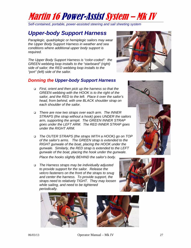
Upper-body Support Harness Paraplegic, quadriplegic or hemiplegic sailors may wear the Upper Body Support Harness in weather and sea conditions where additional upper body support is required. The Upper Body Support Harness is “color-coded”: the GREEN webbing loop installs to the “starboard” (right) side of sailor; the RED webbing loop installs to the “port” (left) side of the sailor.
Donning the Upper-body Support Harness
First, orient and then pick up the harness so that the GREEN webbing with the HOOK is to the right of the sailor, and the RED to the left. Place it over the sailor’s head, from behind, with one BLACK shoulder strap on each shoulder of the sailor.
There are now two straps over each arm. The INNER STRAPS (the strap without a hook) goes UNDER the sailors arm, supporting the armpit. The GREEN INNER STRAP goes under the LEFT ARM. The RED INNER STRAP goes under the RIGHT ARM.
The OUTER STRAPS (the straps WITH a HOOK) go on TOP of the sailor’s arms. The GREEN strap is extended to the RIGHT gunwale of the boat, placing the HOOK under the gunwale. Similarly, the RED strap is extended to the LEFT gunwale of the boat, placing the hook under the gunwale.
Place the hooks slightly BEHIND the sailor’s body.
The Harness straps may be individually adjusted to provide support for the sailor. Release the velcro fasteners on the front of the straps to snug and center the harness. To provide support, the straps need to relatively TIGHT. They may loosen while sailing, and need to be tightened periodically.

Martin 16 Power-Assist System – Mk IV Self-contained, portable, power-assisted steering and sail sheeting system
06/03/13 Operator Manual – Mk IV 28
Before you go sailing… When the Power-Assist System components have been installed, perform the following functional tests of the system at the dockside.
Check the Battery Meter. Every ten seconds, it should cycle all five LEDs from left to right and then back again, indicating that the battery is fully charged.
The WINDLASS LAMP should be flashing ON then OFF to indicate that the main
computer is functioning correctly.
Adjust the JIB SLOT TRIM sheet The Windlass adjusts both sails in unison. It is important that the RELATIVE position of the jib sail with respect to the main sail be adjustable. This is done by adjusting the JIB TRIM sheet as follows.
RELEASE the JIB TRIM sheet from the cleat located at the TOP LEFT of the Cleat Console.
Operate the joystick FORWARD momentarily. The Winch should operate, letting both the JIB SHEET and MAIN SHEET “out”, spooling line off of the drums.
Now check that both sails are clear to move (release the MAIN BOOM PREVENTER clip from the shroud so that the main boom swings freely)
Operate the joystick BACK, spooling in both the main and jib sheets smoothly onto both winch drums (clear snags and tangles in the sheets as required). Operate the Windlass until both sails come to the centerline of the boat. If one sail comes to the centerline before the other, tighten or release the JIB SLOT TRIM sheet so that they both come to the centerline at the same time. Cleat the JIB SLOT TRIM sheet.
Once adjusted, for safety while on the dock, operate the Windlass to let both sheets all the way OUT. Then clip the MAIN BOOM PREVENTER to the shroud.
Fine adjustments may be made to the JIB SLOT TRIM at any time while sailing.

Martin 16 Power-Assist System – Mk IV Self-contained, portable, power-assisted steering and sail sheeting system
06/03/13 Operator Manual – Mk IV 29
Check (manual) Joystick is Centered While using power-assisted steering, the manual JOYSTICK (in front of sailor) provides an important visual indicator of the position of the rudder. It’s important to check that it is properly centered before you leave the dock:
Operate the Power-Assist System joystick to move the RUDDER to a centered position. Now look at the (manual) JOYSTICK. If it is NOT centered, adjust the STEERING LINES on the aft deck until it is centered.
Check Tiller Rod is Centered While using power-assisted steering, the action of the steering must be centered to avoid loosing control or damage to the mechanics.
Check that there is nothing in the way of the JOYSTICK (the sailor’s hands or legs), the tiller or the rudder. Operate the joystick to move the rudder all the way to PORT. WATCH THE ACTION OF THE TILLER ROD AND RUDDER and if it seems to be stressed in any way, STOP! If it is adjusted correctly, the M16 Tiller will reach its maximum travel when it is about ½” from the block on the aft deck.
Now operate the joystick to go all the way to STARBOARD. If it is adjusted correctly, the M16 Tiller will reach its maximum travel when it is about ½” from the block on the aft deck
If the action of the rudder is not centered (i.e. more to either PORT or STARBOARD), loosen the lock nut on the Tiller Rod and adjust the length of the rod to center the action.
Check Sip&Puff Module operation If you are using a Sip&Puff Module, ask the sailor to check the HELM and WINDLASS operation via the Sip&Puff interface. Check that the Sip&Puff Stalk is securely fastened to the sailor’s lifejacket and that it may not be jarred loose while sailing. Check that the Sip&Puff Module is securely fastened to the cockpit wall and that it may not be jarred loose while sailing.
Check Wireless Remote Control operation (option) If you are using a Wireless Remote Controll, orient the key fob and check the system functions. Walk down the dock at least 25 or more feet and retest the key fob functions. The key fob is not waterproof so, as a precaution, place it in a plastic bag if it could get wet while sailing.
Check Electric Bilge Pump operation (option) An Electric Bilge Pump may be installed on the floor of the cockpit ahead of the keel, with the discharge hose connected at the top of the keel box, under the splash deck. The Bilge Pump has a float switch that will automatically activate the pump if a significant amount of water enters the cockpit.

Martin 16 Power-Assist System – Mk IV Self-contained, portable, power-assisted steering and sail sheeting system
06/03/13 Operator Manual – Mk IV 30
Warning to Operator The Martin 16 Power-Assist System is an ASSISTIVE DEVICE, intended to assist sailors with limited hand function to operate sailboats independently. INVENTURE MANAGEMENT LIMITED provides no specific warranties or claims of the Martin 16 Power-Assist System’s "fitness for use" for any person, on any particular vessel or sailing conditions. Sailing is a dangerous sport and the operator uses the Martin 16 Power-Assist System at his/her own risk. Operators are responsible for receiving proper training in the use of the Martin 16 Power-Assist System and for taking normal and appropriate precautions while using the system. Always have able-bodied persons on board your vessel so that, in conditions of inclement weather or when emergency maneuvers are required, they may disengage the Martin 16 Power-Assist System and steer the boat manually. In the event that the Martin 16 Power-Assist System malfunctions for any reason while sailing, always be prepared to revert to manual steering control.
Caution while sailing Over six years of daily use in a wide variety of sailing venues, wind and sea state conditions, the Power-Assist System has proven to provide reliable power-assisted steering and sheeting control of a Martin 16 sloop. The system allows sailors with significant disabilities to safely and independently control their Martin 16. Nevertheless, the system does not provide the same level of response, feedback and “feel” that manual systems do. Sailors are required to be prudent in their use of the equipment and follow diligent safety precautions: The Power-Assist System will not respond to steering commands as quickly
as the helm may be turned manually (Hard-over-PORT to Hard-over-Starboard takes about 4 seconds). Be aware of this limitation and be cautious when maneuvering at slow speeds around docks, or in close proximity to other boats or hazards.
The Power-Assist System and Windlass electric motors are powerful enough to cause harm to clothing and paralyzed limbs. Make sure that the sailor’s clothing and paralyzed limbs are clear of the action of the Windlass and the Joystick when under power assist.
In heavy winds and waves, the system will draw more power and the battery
will discharge more quickly. If you are using an Electric Bilge Pump and shipping a lot of water, THE BATTERY MAY ONLY LAST 1 – 2 HOURS.

Martin 16 Power-Assist System – Mk IV Self-contained, portable, power-assisted steering and sail sheeting system
06/03/13 Operator Manual – Mk IV 31
Keep an eye on the battery meter and be prepared to revert to manual operation if required at any time.
In the event that the Power-Assist System malfunctions for any reason while
sailing, always be prepared to revert to manual steering control by removing the EMERGENCY DISENGAGE FAST PIN on the HELM DRIVE Motor. Sailors not capable of doing this on their own should always sail with an able-bodied Sailing Companion.
In the event that the WINDLASS malfunctions for any reason while sailing,
always be prepared to revert to manual sheeting by pulling the EMERGENCY RELEASE PINS on each of the winch drums. Once released, the drums rotate freely allowing manual sheeting. Sailors not capable of doing this on their own should always sail with an able-bodied Sailing Companion.
Power-Assist Systems are often used in Disabled Sailing Programs shared
among a number of sailors and operated by volunteer staff. It is recommended that ONE mechanically-oriented person be made responsible for a shared system, to assure that the system is properly maintained and that sailors and volunteers receive the necessary training in safe use of the Systems.

Martin 16 Power-Assist System – Mk IV Self-contained, portable, power-assisted steering and sail sheeting system
06/03/13 Operator Manual – Mk IV 32
Caring for your M16 Power-Assist System When not in use, remove and store the System Modules. The Power-
Assist System Modules are intended to be removed from the boat and stored in a cool, dry place when not in use. DO NOT LEAVE THE COMPONENTS ON THE BOAT OR OUTSIDE IN THE WEATHER WHEN NOT IN USE.
Joystick Module, Sip & Puff Module and Battery Module are housed in a
weatherproof enclosure, but is not guaranteed to be waterproof. The sensitive electronic components are located at the top of the system so that even if water penetrates the enclosure, it should not damage the electronics. Under normal use there is no reason to open the Joystick Module enclosure. In order to maintain the integrity of the weatherproof seals in the system:
REPLACE caps tightly over electrical connectors when they’re not in
use. Spray some marine grade electrical lubricant into the connectors periodically.
CLOSE the VENT on the Battery Module when sailing, or exposed to salt or fresh water spray/splash.
RINSE the entire system with fresh water after sailing. DO NOT use a high-pressure hose. Wipe the components down with a dry rag before storing. NOTE: This is very important when used in salt water.
OPEN the VENT on the Battery Module when charging. CLEAN CONNECTORS and spray with a moisture displacing fluid
such as BOESHIELD T-9 (available at WEST MARINE stores). Protect the joystick – it is a mechanically sensitive switching device. Be
careful to protect it from impact and abuse when using the system, when transporting it, and when it’s stored. Check the integrity of the rubber “bellows” on the Joystick for cracks or cuts and replace it if necessary.
CAUTION: Power-Assist Modules are NOT warranted against water
damage. Due to the number of exposed electrical connectors, the possibility of the vent being left open and the susceptibility to abuse, the Power-Assist Modules are not warranted against water damage. The Power-Assist Joystick Module is a sensitive computer product subject to harsh conditions. Under good care, these Modules are water tight and will operate reliably for years of service. IT IS THE OWNER’S RESPONSIBILITY TO TREAT THE POWER-ASSIST JOYSTICK MODULE WITH CARE.

Martin 16 Power-Assist System – Mk IV Self-contained, portable, power-assisted steering and sail sheeting system
06/03/13 Operator Manual – Mk IV 33
Charging the Battery Module When not sailing, the Battery Module is designed to be constantly on
“CHARGE”, even for extended periods (i.e. over winter months). When not in use, STORE YOUR BATTERY MODULE IN A COOL, DRY LOCATION, AND PLUG IN THE INTELLIGENT BATTERY CHARGER. The Intelligent Battery Charger supplied with your system draws very little current, will not overcharge the GEL CELL battery, and will keep the battery in top condition. When not in use, if you do not have the system on CHARGE, the batteries will “self-discharge” over time. This may cause irreversible damage to the battery.
CAUTION: Always use the Intelligent Battery Charger supplied with the Power-Assist system. When GEL TYPE batteries are "short" circuited, or over-charged" by the wrong kind or battery charger, the battery may vent hydrogen gas, which is highly flammable.
CAUTION: before connecting your charger, assure that the VENT IS OPEN. Leave the vent open during charging.
Intelligent Battery Charger is perfectly matched to the GEL-TYPE battery
technology used in the Battery Module. This “global” multi-voltage charger 1) is compatible with any electric system in the world; 2) will charge battery to full capacity in less than three hours; 3) can be left on “charge” indefinitely, without risk of damage caused by over-charging the Battery Module, and 4) is UL, CSA and CE Approved. CAUTION: common automotive or marine battery chargers are designed for larger, lead-acid type batteries, and can damage the Battery Module battery if left on charge for more than one hour.
If using a boat’s “House Battery” as the 12V power supply for your Power-
Assist System, follow the charging procedure recommended by the manufacturer of the boat’s battery system.
Martin 16 Power-Assist System – Mk IV Self-contained, portable, power-assisted steering and sail sheeting system
06/03/13 Operator Manual – Mk IV 34
Warranty The Martin 16 Power-Assist System is constructed of high quality marine/automotive components by INVENTURE MANAGEMENT LIMITED. INVENTURE MANAGEMENT LIMITED warranties the system components for a period of 1 year from the date of shipment. No warranty is provided for: the battery water damage of electronic
components. mechanical damage to any
component that results from neglect or abuse.
Systems must be shipped to INVENTURE MANAGEMENT LIMITED for warranty repairs. If your Power-Assist System does not operate as expected, please call or e-mail: Steve Alvey 403-870-7210 ([email protected]).
Fair Sailing!

Martin 16 Power-Assist System – Mk IV Self-contained, portable, power-assisted steering and sail sheeting system
06/03/13 Operator Manual – Mk IV 35
Appendix A: Spare / Replacement parts
Part # Description Location
A134 ST 4000+ HELM DRIVE rudder drive
A700 Helm Drive Pedestal Mount (D030) Mounting socket
A137 Tiller pushrod Pushrod
A138 pushrod turnbuckle end pushrod turnbuckle end
A140 3/16" fastpin 3/16" fastpin
A141 Tiller cross arm rudder head
W204 Windlass power cable assembly
BP499 Electric Bilge Pump
BP403 Bilge pump discharge hose 3/4" hose x 3'
BM599 Battery Module
BC699 Intelligent Battery Charger
S398 Sip & Puff stalk with chest mounting plate (personal)
A802 Wireless Remote Control – key fob
A807 Upper Body Support Harness
A123 Joystick Module – computer
A103 Joystick Module – replacement joystick
S300 Sip & Puff Module - computer (less switches)
S330 Sip & Puff Module - Pneumatic switches (set of 3)
S398 Sip & Puff stalk with chest mounting plate (personal)
P1600 Pelican 1600 custom shipping case To order spare or replacement parts, go to www.martin16.com : Steve Alvey 403-870-7210 fax 403-233-2285 [email protected]


![[Modelik 1997 02] - WWI British MK-IV Male](https://img.dokumen.tips/doc/110x75/577cc44e1a28aba71198db2d/modelik-1997-02-wwi-british-mk-iv-male.jpg)