Embed Size (px)
Citation preview

21 - 26 April 2018 Dubai International Convention
& Exhibition Centre, UAE
ITA - AITES WORLDTUNNEL CONGRESS
POSTER PAPERPROCEEDINGS

2 3
HYDRAULIC ASSESSMENT OF TUNNEL- DESIGNED FOR DIVERSION AND DEPLETION
Balkrishna Shankar ChavanScientist-D, Central Water and Power Research Station, [email protected]
ABSTRACT
Increasing urban population and the pace of industrial and other developments led to increase in water demand. Many of metropolitan and urban cities are facing acute shortage of water for domestic and industrial purposes To reduce the stress on water supply infrastructure, existing water sources are utilized to fullest and new sources are continuously added to augment the water supply. Major problems in design of tunnel for water flow are flow conditions in approach to tunnels, in tunnel and downstream of tunnel. Even though art of tunneling is very old and well documented, new challenges in design and construction in difficult situations are added over the years. In this paper various hydraulic aspects related to tunnel interlinking rivers are described. Major head loss in tunnel flow is due to friction. Detailed information on investigation by various researchers related to friction factor is attached in Annexure A.
Main aspects of the Project will be presented, including geology, construction sequence, support system, and significant construction events such as TBM excavation passage, excavation through transition zones (diaphragm walls/concrete support). Numerical analyses have been performed to back analyse the observed behaviour and evaluate excavation safety. The developed analyses were capable to reproduce the difference of behaviour at different shafts as well as at the different support systems (diaphragm wall versus sprayed concrete).
Key Words: Discharge, Diversion Tunnel, Explicit Equation, Friction Factor
1. INTRODUCTION
A river diversion tunnel is used to divert river water during construction of a project. Once construction is over, diversion tunnel is plugged before initiating storage of water consequently tunnel part becomes redundant. No universally accepted standards are available for design of temporary structures like coffer dams and diversion tunnels. Tunnel construction has high costs and usually adopted when other solutions are unfeasible. Length of tunnel is kept minimum as possible. To minimize the project cost, part of diversion tunnel can be reused for depletion of reservoir storage. There are instances where part of river diversion tunnels have been used as depletion tunnel after construction of dam is completed. In India projects such as Yamuna, Doyang, Nagarjunsagar, Salal have successfully used the concept of multipurpose tunnel for diversion of river flow and depletion of reservoir. Hydraulic design associated with such tunnels has to function satisfactorily for high discharge at low head during construction and also high head low discharge during operation period of project. Present paper describes hydraulic problems associated with design of diversion cum depletion tunnel. Methodology adopted to arrive at solutions for design parameters in selecting flood flow, tunnel flow capacity during diversion as well as depletion, transitions in shape, energy dissipater at tunnel exit and smooth return of flow to river downstream of the structure.
1.1 Need for diversion of water Urban centers are providing job opportunities, educational facilities and better living, because of which people migrate to cities. The rate of population growth of metropolitan and urban cities of India is unprecedented. Mumbai being the capital city of the state of Maharashtra is also the commercial and financial capital of the country. Actual growth of city and forecast is shown in Figure. 1.
Figure 1: Population Growth of Mumbai City.
1.2 To meet increased demand of water of Mumbai urban agglomerate, a proposal of interlinking Damanganga and Panjal rivers is proposed.The link envisages transfer of balance available water at the proposed Bhugad reservoir across Damanganga river and at the proposed Khargihill reservoir across Vagh river, a tributary of Damanganga river, in Damanganga basin for augmenta-tion of water supply to Greater Mumbai to meet its domestic and industrial water requirements in the near future. The Bhugad and Khargihill reservoirs (proposed by NWDA) and Pinjal reservoir (proposed by Government of Maharashtra across Pinjal river, a tributary of Vaitarna river) are proposed to be connected through pressure tunnels. The purpose is to make the combined water from Bhugad and Khargihill reservoirs to reach Pinjal reservoir from where further arrangements for transmitting the water to Greater Mumbai will be made by Municipal Corporation of Greater Mumbai (MCGM) and Mumbai Metropolitan Region Development Author-ity (MMRDA)[6].
The salient details of Damanganga-Pinjal link project are briefly described below:• A 826.60 m long composite dam is proposed on Damanganga river near village Bhugad in Peint taluka of Nasik district of Maharashtra State and very near to bor-der of Valsad district of Gujarat. The FRL, of the dam fixed on the basis of detailed Surveys & Investigations at 163.87 m. The gross and live storage capacities of the storages are 426.39 Mm3 and 400.00 M m3 respectively. The maximum height of dam is 68.63 metres.
• A 16.85 km long Bhugad-Khargihill link tunnel with 5.0 m diameter connecting Bhugad and Khargihill reservoirs below their minimum draw down levels (MDDLs)is proposed.
• A 572.80 m long composite dam across river Vagh at Khargihill site near village Behadpada in MokhadaTaluka of Thane district of Maharashtra State is proposed. The FRL, of the dam fixed on the basis of detailed Surveys & Investigations at 154.52 m. The gross and live storage capacities have been fixed as 460.79 Mm3 & 420.50 Mm3 respectively. The maximum height of dam shall be 75.62m.
4 5
• A 25.70 km long Khargihill-Pinjal link tunnel with 5.25 m diameter connecting Khargihill and Pinjal reservoirs below their MDDLs.
• A 681 m long Pinjal dam on river Pinjal (tributary of Vaitarna river) near village Khidse in Jawhar taluka of Thane district has been proposed by Govt.of Mahar-ashtra. The FRL, have been fixed on the basis of detailed Surveys & Investigations by Government of Maharashtra as 141.00 m. The gross and live storage capacities have been fixed as 413.57 Mm3 and 401.55 Mm3 respectively.
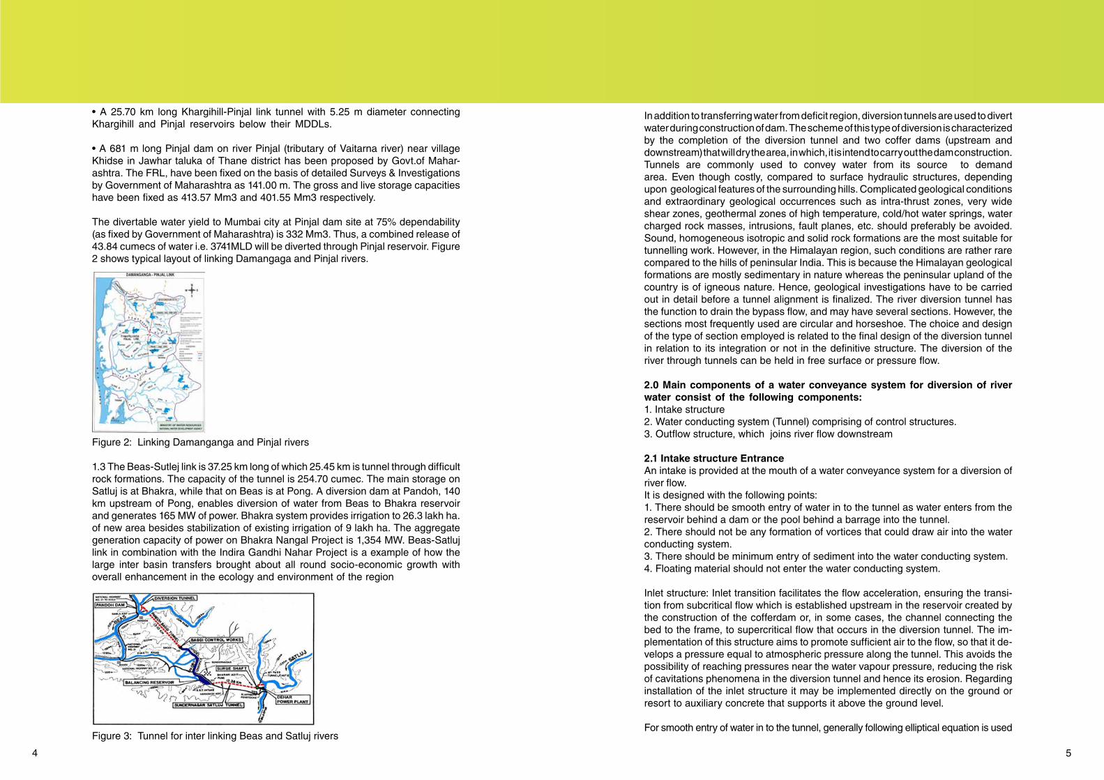
The divertable water yield to Mumbai city at Pinjal dam site at 75% dependability (as fixed by Government of Maharashtra) is 332 Mm3. Thus, a combined release of 43.84 cumecs of water i.e. 3741MLD will be diverted through Pinjal reservoir. Figure 2 shows typical layout of linking Damangaga and Pinjal rivers.
Figure 2: Linking Damanganga and Pinjal rivers
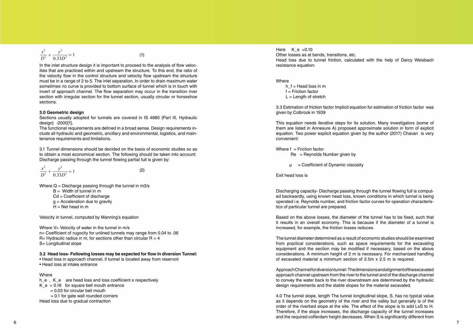
1.3 The Beas-Sutlej link is 37.25 km long of which 25.45 km is tunnel through difficult rock formations. The capacity of the tunnel is 254.70 cumec. The main storage on Satluj is at Bhakra, while that on Beas is at Pong. A diversion dam at Pandoh, 140 km upstream of Pong, enables diversion of water from Beas to Bhakra reservoir and generates 165 MW of power. Bhakra system provides irrigation to 26.3 lakh ha. of new area besides stabilization of existing irrigation of 9 lakh ha. The aggregate generation capacity of power on Bhakra Nangal Project is 1,354 MW. Beas-Satluj link in combination with the Indira Gandhi Nahar Project is a example of how the large inter basin transfers brought about all round socio-economic growth with overall enhancement in the ecology and environment of the region
Figure 3: Tunnel for inter linking Beas and Satluj rivers
In addition to transferring water from deficit region, diversion tunnels are used to divert water during construction of dam. The scheme of this type of diversion is characterized by the completion of the diversion tunnel and two coffer dams (upstream and downstream) that will dry the area, in which, it is intend to carry out the dam construction. Tunnels are commonly used to convey water from its source to demand area. Even though costly, compared to surface hydraulic structures, depending upon geological features of the surrounding hills. Complicated geological conditions and extraordinary geological occurrences such as intra-thrust zones, very wide shear zones, geothermal zones of high temperature, cold/hot water springs, water charged rock masses, intrusions, fault planes, etc. should preferably be avoided. Sound, homogeneous isotropic and solid rock formations are the most suitable for tunnelling work. However, in the Himalayan region, such conditions are rather rare compared to the hills of peninsular India. This is because the Himalayan geological formations are mostly sedimentary in nature whereas the peninsular upland of the country is of igneous nature. Hence, geological investigations have to be carried out in detail before a tunnel alignment is finalized. The river diversion tunnel has the function to drain the bypass flow, and may have several sections. However, the sections most frequently used are circular and horseshoe. The choice and design of the type of section employed is related to the final design of the diversion tunnel in relation to its integration or not in the definitive structure. The diversion of the river through tunnels can be held in free surface or pressure flow.
2.0 Main components of a water conveyance system for diversion of river water consist of the following components: 1. Intake structure 2. Water conducting system (Tunnel) comprising of control structures. 3. Outflow structure, which joins river flow downstream
2.1 Intake structure Entrance An intake is provided at the mouth of a water conveyance system for a diversion of river flow. It is designed with the following points:1. There should be smooth entry of water in to the tunnel as water enters from the reservoir behind a dam or the pool behind a barrage into the tunnel. 2. There should not be any formation of vortices that could draw air into the water conducting system. 3. There should be minimum entry of sediment into the water conducting system. 4. Floating material should not enter the water conducting system.
Inlet structure: Inlet transition facilitates the flow acceleration, ensuring the transi-tion from subcritical flow which is established upstream in the reservoir created by the construction of the cofferdam or, in some cases, the channel connecting the bed to the frame, to supercritical flow that occurs in the diversion tunnel. The im-plementation of this structure aims to promote sufficient air to the flow, so that it de-velops a pressure equal to atmospheric pressure along the tunnel. This avoids the possibility of reaching pressures near the water vapour pressure, reducing the risk of cavitations phenomena in the diversion tunnel and hence its erosion. Regarding installation of the inlet structure it may be implemented directly on the ground or resort to auxiliary concrete that supports it above the ground level.
For smooth entry of water in to the tunnel, generally following elliptical equation is used
6 7
(1)
In the inlet structure design it is important to proceed to the analysis of flow veloc-ities that are practiced within and upstream the structure. To this end, the ratio of the velocity flow in the control structure and velocity flow upstream the structure must be in a range of 2 to 5. The inlet separation. In order to drain maximum water sometimes no curve is provided to bottom surface of tunnel which is in touch with invert of approach channel. The flow separation may occur in the transition river section with irregular section for the tunnel section, usually circular or horseshoe sections.
3.0 Geometric designSections usually adopted for tunnels are covered in IS 4880 (Part III, Hydraulic design) -2000[1]. The functional requirements are defined in a broad sense. Design requirements in-clude all hydraulic and geometric, ancillary and environmental, logistics, and main-tenance requirements and limitations.
3.1 Tunnel dimensions should be decided on the basis of economic studies so as to obtain a most economical section. The following should be taken into account: Discharge passing through the tunnel flowing partial full is given by:
(2)
Where Q = Discharge passing through the tunnel in m3/s B = Width of tunnel in m Cd = Coefficient of discharge g = Acceleration due to gravity H = Net head in m
Velocity in tunnel, computed by Manning’s equation
Where V= Velocity of water in the tunnel in m/sn= Coefficient of rugocity for unlined tunnels may range from 0.04 to .06 R= Hydraulic radius in m, for sections other than circular R = 4S= Longitudinal slope
3.2 Head loss- Following losses may be expected for flow in diversion Tunnel: • Head loss in approach channel, if tunnel is located away from reservoir • Head loss at intake entrance
Where h_e , K_e are head loss and loss coefficient s respectivelyK_e = 0.16 for square bell mouth entrance = 0.03 for circular bell mouth = 0.1 for gate wall rounded corners Head loss due to gradual contraction
Here K_e =0.10 Other losses as at bends, transitions, etc. Head loss due to tunnel friction, calculated with the help of Darcy Weisbach resistance equation:
Where h_f = Head loss in m f = Friction factor L = Length of stretch
3.3 Estimation of friction factor Implicit equation for estimation of friction factor was given by Colbrook in 1939
This equation needs iterative steps for its solution. Many investigators (some of them are listed in Annexure A) proposed approximate solution in form of explicit equation. Two power explicit equation given by the author (2017) Chavan is very convenient:
Where f = Friction factor Re = Reynolds Number given by
μ = Coefficient of Dynamic viscosity
Exit head loss is
Discharging capacity- Discharge passing through the tunnel flowing full is comput-ed backwardly, using known head loss, known conditions in which tunnel is being operated i.e. Reynolds number, and friction factor curves for operation characteris-tics of particular tunnel are prepared.
Based on the above losses, the diameter of the tunnel has to be fixed, such that it results in an overall economy. This is because if the diameter of a tunnel is increased, for example, the friction losses reduces.
The tunnel diameter determined as a result of economic studies should be examined from practical considerations, such as space requirements for the excavating equipment and the section may be modified if necessary, based on the above considerations. A minimum height of 2 m is necessary. For mechanized handling of excavated material a minimum section of 2.5m x 2.5 m is required.
Approach Channel for diversion tunnel- The dimensions and alignment of the excavated approach channel upstream from the river to the tunnel and of the discharge channel to convey the water back to the river downstream are determined by the hydraulic design requirements and the stable slopes for the material excavated.
4.0 The tunnel slope, length The tunnel longitudinal slope, S, has no typical value as it depends on the geometry of the river and the valley but generally is of the order of the riverbed slope at the site. The effect of the slope is to add LxS to H. Therefore, if the slope increases, the discharge capacity of the tunnel increases and the required cofferdam height decreases. When S is significantly different from
1
33.0 2
2
2
2
=+D
yDx
1
33.0 2
2
2
2
=+D
yDx

8 9
the average value assumed, the effect on the cofferdam height estimated from guides in this study should be accounted for. A circular diameter (D) of the tunnel is used to represent and compute the tunnel cross-sectional area available for the flow. In the case of the horseshoe section, the equivalent circular section should be employed. L depends on the extent of the site needed to remain dry and is typical-ly a few tens of meters more than the base width of the dam. It is generally greater for embankment dams than for concrete dams. In any given project, L is fairly fixed and is not subject to optimization here. In the optimization attempt, D and H are inter-related and vary together. Greater H requires smaller D and vice versa.Longer tunnels are generally associated with smaller optimum diameter-Dopti-mum regardless of Q and W and the support type. When the tunnel is very long, an overly large tunnel must be avoided and heightening of the cofferdam should be examined instead. It is prudent that some who follow the tradition of determining D only by Q and W often overlook the simple fact of dependency of Doptimum on L.Reservoir depletion tunnel comprises three sub-structures: Inlet Structure, Tunnel body and Outlet Structure. Section of a depletion tunnel studied at Central Water and Power Research Station is shown in Figure 4.
5.0 Tunnels Tunnels need to be designed and constructed in an efficient manner for the best performance. The Bureau of Indian Standards code IS: 4880-1976 “Code of practice for design of tunnels conveying water” (Parts 1 to 4)[1] provides guidelines for design of a tunnel under various situations. The following are the salient points.
5.1 Tunnel layout The first aspect that needs to be decided for a tunnel is the alignment, that is, the route layout of the tunnel in plan. Figure 5 shows the possible alignment for the tunnel water conveyance system for a diversion of water through tunnel. The inlet structure geometry must be hydrodynamic, both in plan and in longitudinal profile to avoid flow separation. The flow separation may occur in the transition river section with irregular section for the tunnel section, usually circular or horseshoe sectionsThe layout is usually governed by the geological features of the surrounding hills. Complicated geological conditions and extraordinary geological occurrences such as intra-thrust zones, very wide shear zones, geothermal zones of high temperature, cold/hot water springs, water charged rock masses, intrusions, fault planes, etc. should preferably be avoided. Sound, homogeneous isotropic and solid rock formations are the most suitable for tunnelling work. However, in the Himalayan region, such con-ditions are rather rare compared to the hills of peninsular India. This is because the Himalayan geological formations are mostly sedimentary in nature whereas the pen-insular upland of the country is of igneous nature. Hence, geological investigations have to be carried out in detail before a tunnel alignment is finalized.
Figure 4. Diversion Tunnel and Depletion Tunnel arrangement in the Model
Figure 5. Layout plan for Diversion and Depletion Tunnel
5.2Diversion tunnel body: The flow in a river diversion tunnel should occur in supercritical scheme to provide quick acceleration required by deploying of upstream structure. In the river diversion tunnel design it should be noted that in the river diversion through this structure, the flow depth should progress to uniform depth. Thus, it is necessary to define under which conditions the flow is to proceed along the diversion tunnel. Therefore, it is possible to conclude the existence of hydraulic jumps inside the tunnel and determine its location. Studying the flow conditions inside the tunnel consists of analyzing the flow depths along the tunnel by defining the backwater curves. Thus, it is important to trace the backwater curves for diversion tunnel with the goal of establishment the various flow depths along the structure allowing the flow classification.
Flow conditions in tunnel: The occurrence of hydraulic jumps inside the river diversion tunnel can cause structural problems. By establishing the different depths inside the tunnel, it is possible to determine the amount of total movement inside it and the hydraulic jump position. Knowing the flow depths is very important in the study of the river diversion tunnel, so it is imperative to establish backwater curves inside the tunnel. This computation is based on the Bernoulli’s theorem.
Free surface flow: In most cases, flow takes place in free surface and should not exceed 70% of the tunnel capacity. When deploying a river diversion with pressure flow, it must be ensured that the structure’s altimetry track allow the respective domes to always be situated below the isometric line to avoid depressions that may cause structural and hydraulic inconvenient. The study of flow through the tunnel is hampered by the tunnel geometry. The tunnel cross section assumes generally circular or horseshoe geometry. In case of using a river diversion tunnel is possible to convert it in the bottom discharge of the final structure. This approach has advantages, especially in project costs.
The location of diversion tunnel or tunnels is affected by topography, abutment foundation conditions, hydraulic requirements, and economy of construction. Except for some high-head dams, it usually is economical to place an outlet tunnel near stream elevation and use it for diversion during construction. A tunnel should be located far enough into the abutment to obtain adequate cover for the character of rock encountered, and the tunnel alignment must meet the hydraulic requirements. The most economical location to pass around or under the dam and meet the

10 11
foregoing requirements should be selected. An alternate plan used for some deep reservoirs has a high-level intake at the head of an inclined tunnel connecting with a tunnel through the abutment near river level. After serving its purpose of diversion during construction, the low-level tunnel is plugged at the upstream side of the intersection and the inclined tunnel and downstream portion of the low-level tunnel with a connecting curved transition from the permanent outlet. This plan may be economical and satisfactory under special conditions where the reservoir is very deep, the minimum water surface is high, and rock foundation is adequate. Because of the difficult foundation and structural problems involved in this type of construction, thorough foundation investigations and comparative studies should be made and this plan should not be selected without full analysis of its practicability and economy. The advantage of the high-level intakes for a very deep reservoir is the lower intake structure and lower head on intake gates, resulting in a less expensive intake structure. Disadvantages of this type of outlet are: cost of the inclined tunnel, difficulty of obtaining an adequate foundation for the intake structure, and the difficulty of excavation for and the complexity of the transition structure at the junction of the inclined tunnel with the low-level tunnel. Particular care should be taken to obtain high quality concrete, smooth gradual curves, and good alignment at the junction. If the intake structure is located directly over the low-level tunnel, there should be an ample thickness of good, sound rock between the intake base and the tunnel to transmit the foundation loads to the main rock mass. Sometimes conditions may be favourable for locating the intake far enough to one side of the low-level tunnel to simplify the problem of supporting the intake structure. For some high dams, outlet works separate from diversion facilities and located much higher than the river channel may be suitable. In such cases, overall economy may result from use of separate high-level outlets and use of the downstream portion of the diversion tunnel as part of the spillway outlet.
5.3 Number and size of tunnels. The proper selection of number and size of diversion tunnels depends on hydraulic requirements, the maximum size of tunnel which it is practicable to drive in the rock encountered, operating flexibility, and economy of construction. In some instances it may be necessary to limit the size of tunnel in yielding rock to prevent excessive movement in the surrounding rock. Generally the larger the tunnel within practicable driving limits, the more economical it is per unit flow capacity. Also, the approach and discharge channels and the intake structure usually are more economical for fewer tunnels because the reduced width results in less channel excavation and a narrower intake structure. However, if it is necessary to use two parallel gates in each larger tunnel and only one in the smaller, the intake structure may not be reduced and economy may not be affected by use of larger tunnels. The most economical number of tunnels which will meet the other require-ments should be used. A single tunnel is used when, as is frequently the case, the required diameter to handle the entire discharge is not over 20 ft to 25 ft. In order to provide reasonable operating flexibility, a total of not less than two service gates should be provided in the outlet works. In some cases, this requirement may influence the number of tunnels. Detailed design and construction procedures for tunnels are provided in EM 1110-2-2901, A Tunnels and Shafts in Rock[4].
5.4 Influence of downstream levels for diversion tunnelsWhen dimensioning the river diversion tunnel it is important to study the influence of the downstream level into the flow conditions inside the tunnel, once it may not be guaranteed that the establishment of the uniform system within the diversion
tunnel ensures that free surface flow occurs along its entire length. In order to proceed with the study of the downstream level influence, it is necessary to analyze the altimetry placement of diversion tunnel. Submerged flow considerably reduces the discharging capacity of the tunnel. A first stage begins by analyzing the total momentum inside the tunnel, comparing it with the natural bed total momentum. In the case of the natural bed total momentum overcome the values obtained in the tunnel, the hydraulic jump occurs inside the tunnel. Thus it is possible to determine the existence of hydraulic jump, and if there is, proceeding to its location. The occurrence of a hydraulic jump inside the diversion tunnel involves a correction of the upstream altimetry position. The calculation of the flow depths by defin-ing curves backwater enables the calculation of the total momentum into the river diversion enabling comparison with the total momentum in the natural bed and the location of the hydraulic jump.
5.5 Multiple diversion tunnelsFor at least two reasons, the designer may choose multiple (mostly twin) tunnels to carry a large design flood: (I) large cross-section needed to divert large flood is associated with specific problems such as higher tunnel stability risks and expensive support measures, need for more complicated excavation or support equipment, and more risks brought about for the abutments specially when the overburden or the rock quality is not sufficient; (ii) the design flood may not happen during construction and the discharge in a great majority of construction days is much below the design flood. Therefore, twin tunnels may be constructed, one to carry the usual low and average discharges another with a higher invert elevation to carry the additional part of the design flood. When the second one is construct-ed sufficiently higher than the first, it may be mostly used as access road tunnel between upstream and downstream parts of the dam during construction, a double arch 180m high concrete dam under construction in southwest of Iran). The designer may choose to apply support but avoid RC lining in the second tunnel.
6.0 Tunnel exit It is also essential to design the entry and exit points of the tunnel very carefully. Where the tunnel emerges out of the hill slope, a structure in the form of an arch is usually provided, which is called the portal. Since at this point the water leaves the tunnel, it is prone to hydraulic head loss and erosion. Proper transition shape has to be provided to keep the loss minimum and to avoid cavitations. The length and slope of the transition depends upon the velocity and flow conditions prevailing in the tunnel, economics, construction limitations, etc. It is generally preferred that a hydraulic model study is conducted to arrive at an efficient but economic transition. tunnel. When a circular tunnel flowing partly full empties into a chute, the transition from the tunnel section to one with a flat bottom may be made in the open channel downstream from the tunnel portal or it may be made within the tunnel so that the bottom will be flat at the portal section. Ordinarily, the transition should be made by gradually decreasing the circular quadrants from full radius at the upstream end of the transition to zero at the downstream end. For usual installations the length of the transition can be related to the exit velocity. An empirical rule which may be used to design a satisfactory transition for velocities up to 6 m/s is as follows:
Where L = length of transition in m, v = exit velocity in m/s, and D = tunnel diameter in m

12 13
6.1 Outlet Structure: The return diverted flow, through the river diversion, can be made through direct connection to the river or by deploying outlet structure. The deployment of the res-titution structure may have two objectives, the dissipation of excess energy or the recovery of part of the kinetic energy. The need to implant a restitution structure is associated with the fact that the flow in the tunnel that is supercritical or if the downstream section of the tunnel is elevated compared to the river bottom, hinder-ing establishment subcritical conditions in the restitution area. The outlet structure can match the deployment of a transition structure or deployment of stilling basin. Diversion tunnel discharge can be led to directly in to river depending upon gra-dient of river. To avoid bank erosion some form of bank protection is provided. In case of depletion tunnel exits, where high velocity may occur, energy dissipation arrangement has to be provided as shown in fig: 6.It works well as part jet is lifted to 350 splitting and spreading before plunging in to river pool.
Figure 6. Recommended Energy Dissipation arrangement for depletion Tunnel.
7.0Cost Analysis- Following are the main factors affecting overall cost of the tunnela)Capital investmentb) Cost of equipmentsc) Interest charges on capital cost of tunnel, d) Annual maintenance charges,e) Whether lined or unlined and f) Cost of gates and their hoists.
8.0 Tunnel inspection and maintenance:Inspection of tunnel and its maintenance takes an important role in sustainable functioning of the tunnel. Inspection is carried out at lean water levels. Sometime tunnel has to be closed down. As such very little time is available for inspection as compared to other types of tunnels.Another hurdle for inspection of hydraulic tunnels is remoteness.
Cavitations: - Design shall be such that negative pressures are avoided. Cavitation observed at Sardar Sarovar tunnel is shown in Figure 8.
Figure 7. Prototype photograph showing exposed reinforcement inside Tun-nel due to cavitations
Closing of river diversion: For diversion tunnels, it is necessary to close the flow through diversion tunnel to start filling the dam or divert the tributary flow through definitive structures that are completed. The temporary diversion closure can be permanent or temporary (Pinheiro, 2002). In temporary closure, it is common to use a gate. For permanent closing it is implanted a concrete plug inside the diver-sion structure. The planned temporary diversion closure must be programmed according to a study of local flow conditions and the closing of the river coincide with the dry season. The type of diversion structure influences naturally provisional closing. In the case of the structure consist of two diversion tunnels it is possible to make the closing of one of the tunnels continuing the flow to be diverted by other tunnel (ICOLD, 1986)[5].
References:[1] BIS 4880 (Part III, Hydraulic design)-2000, Code of practice for design of tun-nels conveying water.
[2] Balkrishna Shankar Chavan (2017), Unified Equation for Estimation of Friction Factor, Proceedings of 37th IAHR World Congress, Aug13-18, held at Kuala Lum-pur, Malaysia Pages 5885-5893
[3] Bureau of Reclamation (BUREC) 1987, Design of Small Dams, 3rd edition, Bu-reau of Reclamation, Water Resources Technical Publication, Denver.
[4] EM 1110-2-2901, A Tunnels and Shafts in Rock Bureau of Reclamation, Water Resources Technical Publication, Denver
[5] ICOLD. 1986. River Control during Dam Construction, bulletin 48a, Paris. Man-zanares, A.A. 1980.
[6] MMRDA, MCGM, (2006) Development plan for Greater Mumbai

14 15
ANNEXURE-A
TABLE -1. Application of Friction Factor Formulae for estimation of frictional loss in Tunnel flow
BIOGRAPHY
Author is professionally associated with Indian Water Works Association (Life Member), American Society of Civil Engineers (ASCE), International Association for Hydro-Environmental Research (IAHR) and Indian Society for Hydraulics(ISH) as a member. Presently working with Central Water and Power Research Station (CWPRS), India, as a Scientist- D (Chief Research Officer). He did B.E (Civil) in1982 and subsequently M.Tech. (Water Resources Engineering) from Indian .Institute Technology Bombay. The major area of his research was reservoir and appurtenant structures, Water Conductor System, Control Structures, sedimentation in water flow. He was involved in the development of Spillway and Energy Dissipaters, Control Structures and Water Conductor Systems. Worked on many prestigious projects in Indian region such as Sardar Sarovar, Narmada (Indira Sagar), Punatsangchhu(Bhutan), Subansiri, Lower Siang, Chamera, Doyang, Hasdeo-Bango projects. While working in CWPRS, he had published over 23 research papers in National and International journals and conferences. Recently worked as a Moderator for sessions of Conference organized by ASCE .

FOR VISITINGTHANK YOU
ITAAITES