Embed Size (px)
Citation preview
Position Sensorless Control of PMSM
Based on a Novel Sliding Mode Observer over
Wide Speed Range
Song Chi, Student Member, and Longya Xu, Fellow IEEEDept. of Electrical and Computer Engineering
The Ohio State University2015 Neil Avenue
Columbus, OH 43210 USA
Abstract- A position sensorless control scheme ofpermanent magnet synchronous machines (PMSM) withoutsaliency is proposed. The rotor position angle of PMSM isestimated by a novel sliding mode observer over a widespeed range including flux-weakening region. A feedback ofthe equivalent control is applied in the sliding modeobserver. Compared to conventional sliding modeobservers (SMO), the proposed approach features theflexibility to design the sliding mode observer with broadoperating range. By properly selecting equivalent controlfeedback gains, the estimation error of rotor position anglecan be reduced in the low-speed range and fast convergenceguaranteed in the high-speed range. Computer simulationand experimental results are presented to verify theproposed sensorless control algorithm.
Keywords-sensorless; PMSM; sliding mode observer; widespeed range
I. INTRODUCTION
Permanent magnet synchronous machines (PMSM)have been increasingly applied for drive applications dueto their high power density, torque to inertia ratio and highefficiency. To achieve the field-oriented control of aPMSM, knowledge of rotor position is required. Usuallythe rotor position angle is measured by a shaft encoder,resolver, or Hall sensors. However, the presence of suchsensors increases the cost and encumbrance of the overallsystem as well as reduces its robustness and reliability.Furthermore, it is difficult to install and maintain aposition sensor due to the limited space and/or rigidenvironment with severe shaft vibration. Therefore, it isdesirable to eliminate position sensors in vector controlPMSM drives.
For this purpose, researches have been conductedwidely in the past two decades. Several main techniquesof sensorless control have been extensively studied forPMSM drives, which can be broadly categorized into twogroups: 1) magnetic-saliency-based and 2) observer-basedestimation. In the first group, the rotor position can beestimated by using inductance variations due to the
magnetic saturation and/or saliency of PMSM.Techniques based on this idea, e.g. the "INFORM"method [1] and the high-frequency signal injectionmethod [2], are playing an important role on thesensorless control of PMSM drives requiring standstilland low-speed operation. Unfortunately such approachesonly work at low speeds for PMSMs with saliency and aretoo complicated to be easily implemented in real-time.The second group includes the Luenberger observer [3],full-order state observer with feedback linearization ofnon-linear state [4], D-state observer [5], and so on.However, the poles and zeros of the system transferfunction may vary due to parameter variations, and modeluncertainties always degrade the performance of theseobservers.
Previous studies show that sliding mode observers(SMO) have attractive advantages of robustness todisturbances and low sensitivity to parameter variationswhen the sliding mode truly happens. In principle, slidingmode approaches can only be achieved by discontinuouscontrol and switching at infinite frequency. In reality,however, no such sliding mode will take place inimplementation due to the limited switching frequencyand sampling rate. As a result, the discretizationchattering problem normally exists. The boundarysolution has been used to solve the chattering problem byreplacing the discontinuous control with a saturationfunction which approximates the sign function in aboundary layer of sliding mode manifold. In such a way,the invariance property of sliding mode is partiallypreserved in the sense that the state trajectories areconfined to a small vicinity of the manifold. However,within the boundary layer, the state behavior and furtherconvergence to zero cannot be guaranteed [6].
For SMO based sensorless control of PMSM, twochallenges have to be dealt with properly: first, the verysmall magnitude of the back-EMF at low speeds and thesecond, the sufficient high switching gain satisfying thenecessary conditions for SMO convergence in the high-speed range. It is known that the minimum operatingspeed and the quality of the estimated rotor position at low
1-4244-0449-5/06/$20.00 ©2006 IEEE IPEMC 2006

speeds depend on the quantization error of discrete-timecontroller. On the other hand, the high switching gaincauses large ripples on the estimated component, resultingin large estimation error.
Peixoto et al proposed a speed control system of aPMSM drive, in which the sliding mode observer wasbuilt to estimate the induced back-EMF, rotor position andspeed. The back-EMF information was obtained from thefiltered switching signals relative to the current estimationerror. To design the switching gain over a wide speedrange may be a challenging job using this observer model[7].Han et al presented a method to estimate the speed of a
PMSM based on sliding mode observer. Lyapunovfunctions were chosen for determining the adaptive lawfor the speed and stator resistance estimator. It can befound that the existence condition of sliding mode was noteasily guaranteed for the convergence of the SMO. Alsothe integration of speed may bring more error on theestimated rotor position angle [8].
Elbuluk et al investigated a SMO for estimating theposition and speed of a PMSM. Instead of directly usingfiltered switching signals by a low-pass filter, an observerwas designed to undertake the filtering task for theestimated back-EMF. It is stated that the observer has thestructure of an extended Kalman filter and is expected tohave high filtering properties [9]. Unfortunately noexperimental results were given to show the feasibility ofthe proposed method. Similar technique has also beendiscussed in [6].Kang et al proposed an iterative sliding mode observer
for the estimation of back-EMF of a PMSM withoutsaliency and thus rotor position angle in high-speed range.By iterating the general SMO recursively several timeswithin a sample period of PI current regulators, chattingcomponents of the estimated currents and back-EMF canbe reduced. However, this method doesn't help much forthe low-speed operation [10].To cope with the foregoing problems, this paper
presents a sensorless vector control algorithm for PMSMswithout saliency. The rotor position angle is estimated bya novel sliding mode observer over a wide speed rangeincluding flux-weakening region. A feedback method ofequivalent control is proposed. By this method theestimation error of rotor position angle can be reduced inthe low-speed range and fast convergence guaranteed inthe high-speed range without chattering problem. Inaddition, the stability analysis is conducted and selectionof the feed back gain discussed. The proposed sensorlesscontrol algorithm is implemented in a fully digital speedcontrol system based on a digital signal processor (DSP),TMS320F2812. Computer simulation and experimentalresults are used to verify its validity.
II. MATHEMATICAL MODEL OF PMSM IN THESTATIONARY REFERENCE FRAME
The dynamic equations of a PMSM without saliency inthe stationary reference frame can be expressed in thematrix form as
is=A is+B(s-is+) (1)
where A = ILsRLS L B=I Ls ]0 Rs ILs 0L lLs
is ViXsSV,Le 1=e.r.sin8re B = Mj=K.0 s f)
L, Rs and Ke refer to the parameters of stator inductance,resistance and back-EMF constant.
III. SLIDING MODE OBSERVER
The sliding mode observer is designed as
is ='A -is +B - (v7 s +I Z- eq +Z)(2)
1 >-1 Z K sign (is -is)
where A =-
RJ/LS RJl-Rs/L,-
i=iC6 =V*sHis =
As_
,z- Fsig4ic, ac)1sig4i -is) = IiSlgivl-ls)=.A -i)
YLo Ls
Bs= AM
iosBs Vr=L
Llf]
k 0LO k-
In (2), 1 is the feedback gain of the equivalent controlZeq, and k, normally positive (k >0), is the switching gainof the discontinuous control Z,. The superscript '*'indicates a command variable.The equivalent control Zeq can be obtained as in
k sign(ias -ias ) 1Zeqeq coZeq=~ ~ ~ ~ ~~L) (3)
s + CO,c: freq_ cutoff

A low-pass filter is used in (3). It is noticed that itscutoff frequency should be designed properlycorresponding to the fundamental frequency of currents.
Fig. 1 shows a block diagram of the proposed slidingmode observer.
0r = -tan- ( sa ) = - Ztan-( )es6 Zeq,6
(7)
It is noticed that the estimated rotor position angle frshould be added by 2Z when the rotation direction isopposite.
IV. STABILITY ANALYSIS
Let the positive definite function,
V = * ST2 S > O
2(8)
Figure 1. Block diagram of the proposed sliding mode observer
To solve the chattering problem, the sign function isreplaced by a saturation function as shown in Fig. 2.When the magnitude of current error is less than Eo, thecontrol Z changes to a saturation function as
Z = - kI (iS - iS )
be a Lyapunov function candidate. Its time derivativealong the system trajectories is of the form
1V =ST.s~A=S T +ST=SAS +SB ( e s + I Zzeq + Z )
(9)
Considering (4) and ,u = 1/ wc , we get
where k, = k /Eo.
k
-EO
zV~ = ST. S
> STAS + STB* +k( I+ 1)STB * sign(S)=F1s +F
=F1+F2
(10)
EO
where-k
Figure 2. Diagram of the saturation function
Considering (1) and (2), we can obtain the dynamicsliding mode motion equation as expressed in
S =A S+B (es + .Zeq +Z)
where S =is -is(4)
Fl T=STAS
FLs{*L5 esa k /Ps ++ sian(isC9]
7 s +1+
+ i S,6 FeS+- k lu + si s }
IJ L Ps + I j fa < o'lsi PsS4 +A i>(< 0
If the switching gain of Z, k, is large enough toguarantee the following [2]
T .S <O (5)
then sliding mode will exist and we get
From (1), we know that A is negative and B positivedefinite. Consequently Fl is negative.
Assuming ,1 is very small with regard to the highcutoff frequency wtcof the low-pass filter, F2 is negativeif the following satisfies.
Leas (6)
Furthermore, the rotor position angle Or can beestimated by using the equivalent control Zeq as follows.
Jk -,S I+l > le,aI
IusL + I
o>k. (I+ I)>| I|j,Imax (1 1)
>
----
i.1 - i1
or 1as - 1a
It is implied that the feedback gain I must be largerthan -1 with any positive switching gain k, i.e. I > -1.
Therefore, the time derivative of V is negative withenough large positive switching gain k, which testifiesto convergence to S(t) = 0 with finite time and therebythe existence of sliding mode.
V. SELECTION OF FEEDBACK GAIN OF EQUIVALENTCONTROL
A. Below the base speed: 0> 1> -1
From (6), we can see that the magnitude of theequivalent control Zeq is always larger than that of theback-EMF with 0> 1 > -1. The rotor position of PMSMis calculated from Zeq. Although the back-EMF issmall at low speed, the estimated Zeq is enlarged byselecting the feedback gain satisfying 0> 1 > -1.Therefore, with the same quantization limits in thereal-time implementation, the proposed observer isable to work at lower speeds, or improve the quality ofthe estimated rotor position angle, equivalentlyextending the minimum operating speed.
B. Above the base speed, i.e. flux-weakening region:I > 0
From (11), it can be seen that the effective switchinggain of the control Z is enlarged by selecting thefeedback gain I > 0. This property results in fasterconvergence rate of the proposed asymptotic observer.
Speed'-a
On the other hand, the switching gain k can bedesigned with smaller value than those in conventionalSMOs under same conditions. By this approach, usingsame low-pass filters, the ripples on the equivalentcontrol Zeq can be reduced, and thus ripples on theestimated position angle are very small.
In the paper, 1= -0.5 below the base speed and 1= 1above the base speed are selected for the computersimulation and experimental testing.
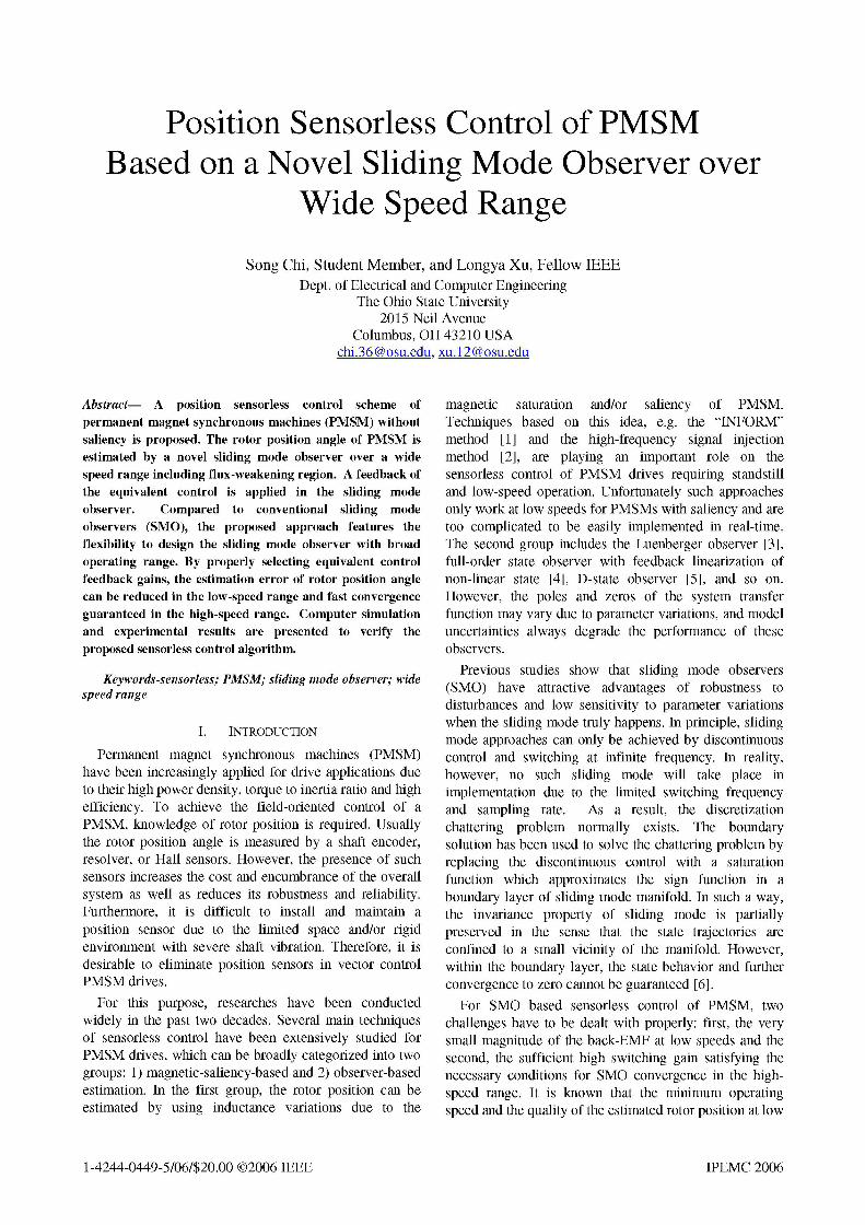
VI. OVERALL CONTROL SYSTEM
Fig. 3 shows a block diagram of the overall controlsystem, which consists of a speed PI regulator, a flux-weakening controller, 2 current PI regulators, a speedcalculator implemented by a Phase-Locked Loop (PLL)and a rotor position estimator by the sliding modeobserver. In addition, the conventional modules forvector control such as Clark, Park and inverse Parktransformation, space vector PWM generation module,a 3-phase power inverter and the PMSM are included.When the speed of the PMSM is above its base speed,the flux-weakening controller will be activated, whichnot only takes over the speed regulation but alsoautomatically generates the required demagnetizingcurrent for the flux-weakening operation.
iPark T
ilculaor Rotor Position
Estimator
Figure 3. Block diagram of overall control system
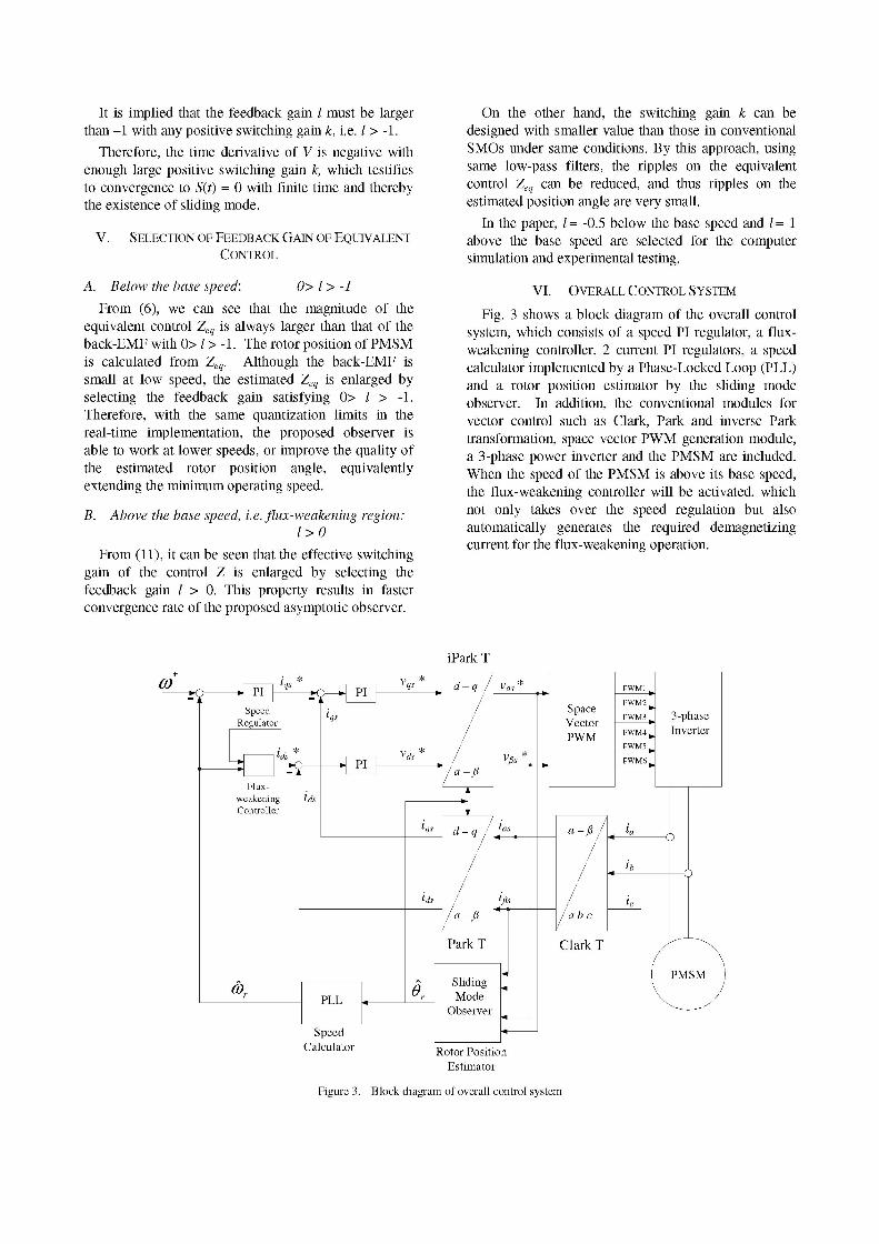
VII. SIMULATION AND EXPERIMENTAL RESULTS
A. Simulation resultsThe proposed position sensorless control algorithm
based on the sliding mode observer was simulated bySimulink/MatLab. The parameters of PMSM were: R, =
16 ohm, Ls= 60 mH and Ke = 0.22 Vs/rad. The base speedwas 250 rpm. The dc bus voltage of the power inverterwas 3 1OV. The space vector PWM algorithm was appliedand updated every 50 ps with respect to the switchingfrequency of 20kHz. Variables in the speed and currentregulators were in per unit. The speed base was defined as
1250 rpm and current base was 7A. The switching gain kof the sliding mode observer was 800. The cutofffrequency of the low-pass filter for obtaining theequivalent control was 400021 rad/s while the maximumfundamental frequency of current was 100021 rad/s.
Sliding Mode Observer (TI 10 Nm, Speed 50 rpm)
0j42 0°63 0 64 0°65 0°66 0°67 0168
-0 01 0 0 -10026 0 65 0066 0067 0.68
100
0 ---- -- -
-1000 62 0.63 0064 065 0.66 0.67 0.66
062 0l3 004 000 000 0 0l0l0 01
0
-0010062 0063 O04 065 0066 0067 0068
1000
00 05 15 2 26 3 0 4 40 ,sample
(a)
Sliding Mode Observer (TI 1 Nm, Speed= 1000 rpm)
O~90706O791 0.7910 01792 0~79250.7 07920 0.7940 01
L0 010~70 079000 0791 07010 0~792 07905 0.793 07920 0.794
6000 ~
79 07000 0791 07010 079.2 07020 0.793 0 7020 0.704
0 79 07 0 0791 0 7910 0 792 07920 0793 07930 0794
0
0~70 07200 0721 07210 0702 07925 0722 0.7935 0.7241000
0
-1000 i ~ i0 00- 1 10-5 205 3 30-! 4 406 0
samnple 10b
(b)
Figure 4. Actual and estimated angle (up) and estimation error (2nd),estimated back-EMF (3 d), measured and estimated current i05 (4th) and
error (5th), and sliding mode control Za (bottom) (a) 1= 0.5, (b) 1=1
Figs.4 shows the simulation results when the motor wasrunning at 50rpm with I = -0.5 in (a) and at 1000rpm withI = 1 in (b). In the two cases, actual and estimatedwaveforms of both rotor position angle and stator currentalmost overlap together with very small errors (muchsmaller than 0.01). In the figure, 0.01 of angle errorrepresents 0.57 electrical degree. In addition, the controlZa was sampled in real time at minimum frequency of 1GHz. Other signals were sampled at fixed 100 kHz. It isnoticed that Za is not aligned with other signals in timeand plotted in sample dots.
B. Experimental resultsAn experimental PMSM drive system was set up to
verify the proposed sensorless control, which included: 1)a 48-pole non-saliency outer-rotor PMSM with its basespeed of 250 rpm, 2) a DSP controller based on aneZdspF2812 DSP board, 3) a three-phase power inverterand 4) a dynamometer coupled with the shaft of thePMSM as load. The switching frequency of powerinverter was 20kHz. Space vector PWM was used for thePWM generation. The dc bus voltage of the powerinverter was 31OV and the maximum current was 7A. Thesampling frequency of the current and voltagemeasurement was 20 kHz. The parameters of PMSMwere: RS=16 ohm, Ls=60 mH and Ke=0.22 Vs/rad, same asin the simulation.
In Figs. 5 and 6, the real rotor position is measured bythe encoder ( 0encoder ) and the estimated one ( OsMo ) bythe proposed sliding mode observer. Hall sensor signalHall_A and phase current ia and ib are also displayed.
Figs.5 shows the experimental results when the motorwas running at 50 rpm (20% base speed) with a constantload of 10 Nm (30% maximum torque) and Fig.6 at 1000rpm (400% base speed) with a constant load of 1 Nm(50% available maximum torque according to speed). Wecan see the well-behaved rotor position estimation fromthe SMO observer and the well-regulated sinusoidalcurrent waveforms. The estimated angle 0SMO aligns with
Oencoder and Hall_A well. The output rotor positionsignals in Fig. 6 are rounded on the bottom corner due tothe limited bandwidth of monitor circuits. The details ofthe measured and estimated rotor position angle wererecored by real-time data logging and shown in Fig. 7.
Figs.8 through 10 show the transient response when themotor was running at 50, 500 and 1000 rpm with step-onand -off load of 10 Nm, 5 Nm and 2 Nm respectively. Asobserved, the speed is well regulated over a wide rangeregardless of load disturbance.
Figs. 11 shows the experimental results when the motorwas accelerated from 50 to 1025 rpm and stayed for 25 sand then decelerated to 50 rpm. The dc bus voltage variedbetween 320V and 280V due to operating conditions. Theload was added with 0.5 Nm. The feedback gain kchanged at 180 rpm with the onset of the flux-weakeningoperation. We can observe the automatically generateddemagnetizing current id, and the good performance of
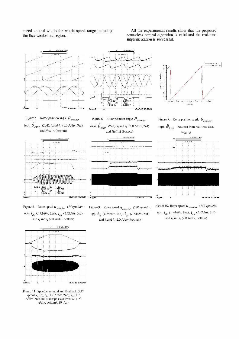
speed control within the whole speed range includingthe flux-weakening region.
All the experimental results show that the proposedsensorless control algorithm is valid and the real-timeimplementation is successful.
Stopped bU
from SMO|| from encoder|
Figure 5. Rotor position angle 0encoder
(up), OSMO (2nd), iaand ib (1.0 A/div, 3rd)and Hall_A (bottom)
05,09,18 16: 34:39lOkn
Figure 6. Rotor position angle 0encoder
(up), 0SMO (2nd), iaand ib (2.0 A/div, 3rd)and Hall_A (bottom)
Figure 7. Rotor position angle 0encoder
(up), OSMO (bottom) from real-time data
loggingV 05,09,18 176 19: 52
T: R:
HALL A Freq IB His.Z0 .49 Hz .792
IA lax 1A HMs1.5210 Ul 790.08nV
Sopwped
Figure 8. Rotor speed n encoder (75 rpmldiv,
up), ids (I. 7A/div, 2nd), iqs (I. 7A/div, 3rd)
and ia and ib (2.0 A/div, bottom)
05:/09/1S 17: 37: 51Ok
...:.....:. ....................................................................... ....... ....... ....
Stopped 2 05/09/18 17:13:04 Stopped 2 05/09/18 17:19:58
Figure 9. Rotor speed n encoder (380 rpm/div, Figure 10. Rotor speed nencoder (757 rpm/div,
up), ids (1.7A/div, 2nd), i (I.7A/div, 3rd) up), ids (1.7A/div, 2nd), iqs (I.7A/div, 3rd)
and ia and ib (2.0 A/div, bottom) and ia and ib (2.0 A/div, bottom)
Stoppied 1 05/091/10 17:38i:09
Figure 11. Speed command and feedback (757rpm/div, up), id, (1.7 A/div, 2nd), iq, (1.7
A/div, 3rd) and stator phase current ias (1.0A/div, bottom), 10 s/div
......................~................. ......... ........ ..
HALL A Freq IB Hns HALL A-399.8 .Hz: 2.I.. U2:0::
IA Max IA Hins1.8420 U 1. 2878 U
J1; 1)~~~~~~~~~~~~* < Main >>
1, v0.0910 0.0915 0.0920 0.0925 0.0930 0.0935 0.0940
time (s)
S OPPed SY'0' 05,109,18 17 :55 :5i Iaa a . a.
-U:-t nnW
Itnnd ^a al E1C*Q
M.il
------ I
1.0
0.9 -1
0.8
0.7
0.6
0.5
0.4
0.3
0.2
0.1
0. 0 -L
.112rC 05/09/16 13:59 :23
VIII. CONCLUSIONS
In this paper, a sensorless vector control scheme ispresented for PMSMs without saliency using a novelsliding mode observer. The rotor position angle isestimated based on the equivalent control signals overwide speed range including flux-weakening region. Bya feedback method of the equivalent control, theestimation error of rotor position angle is reduced in thelow speeds and fast convergence guaranteed in the highspeeds. Stability of the proposed sliding mode isproved by a Lyapunov function. The speed of PMSMis well regulated in the whole speed range regardless ofload disturbance. The validity of the proposed controlalgorithm has been demonstrated by both computersimulation and experimental results.
ACKNOWLEDGMENT
This work was supported by the Research andEngineering Center of Whirlpool.
REFERENCES
[1] M. Schroedl, "Sensorless control of AC machines at low speedand standatill based on the "INFORM" method," in Conf. Rec.IEEE-IAS Annu. Meeting, vol. 1, 1996, pp. 270-277.
[2] M. J. Corley and R. D. Lorenz, "Rotor position and velocityestimation for permanent magnet synchronous machine atstandstill and high speed," in Conf. Rec. IEEE-IAS Annu.Meeting, vol. 1, 1996, pp. 36-41.
[3] K. W. Lim, K. S. Low and M. F. Rahman, "A position observerfor permanent magnet synchronous motor drive," IECONAnnu. ConferenceRecord, pp. 1004-1008, 1994.
[4] Y. Yamamoto, Y. Yoshida and T. Ashikaga, "Sensorlesscontrol of PM motor using full order flux observer," IEEJTrans. Ind. Applt., vol. 124, pp. 743-749, Aug. 2004.
[5] S. Shinnaka, "New "D-state-observer"-based vector control forsensorless drive of permanent-magnet synchronous motors,"IEEE Trans. Ind. Applicat., vol. 41, pp. 825-833, May./June.2005.
[6] Vadim Utkin, J. Guldner and Jingxin Shi, "Sliding modecontrol in electromechanical systems," lIs Edition,Taylor&Francis, 1999.
[7] Z. M. Peixoto, et al., "Speed control of permanent magnetmotors using sliding mode observers for induced emf, positionand speed estimation," in Conf. Rec. IEEE-IAS Annu. Meeting,vol. 2, 1995, pp. 1023-1028.
[8] Y. S. Han, J. S. Choi and Y.S. Kim, "Sensorless PMSM drivewith a sliding mode control based adaptive speed and statorresistance estimator," IEEE Trans. Magnetics, vol. 36, pp.3588-3591, Sept. 2000.
[9] M. Elbuluk and C. Li, "Sliding mode observer for wide-speedsensorless control of PMSM drives," in Conf. Rec. IEEE-IASAnnu. Meeting, vol. 1, 2003, pp. 480-485.
[10] K. Kang, J. Kim and et al, "Sensorless control of PMSM inhigh speed range with iterative sliding mode observer," inConf. Rec.IEEE- APEC'04, vol. 2, 2004, pp. 1111-1116.