Embed Size (px)
Citation preview

Sensorless FOC of PMSM using SmartFusion2 Devices
Reference Guide

Sensorless FOC of the PMSM Control using SmartFusion2 Devices Reference Guide
Table of Contents
Sensorless FOC of PMSM using SmartFusion2 Devices ........................................... 5 Introduction .................................................................................................................................................... 5 References .................................................................................................................................................... 6
Control Theory ............................................................................................................... 7 Permanent Magnet Synchronous Motor ........................................................................................................ 7 Theory of Sensorless FOC ............................................................................................................................ 8 FOC Algorithm Blocks ................................................................................................................................... 9
Software Design ........................................................................................................... 21 Sensorless FOC .......................................................................................................................................... 21 State Definitions........................................................................................................................................... 21 API Function Definition ................................................................................................................................ 22
FPGA Fabric Design .................................................................................................... 29 Fabric Implementation ................................................................................................................................. 29 Principle of Operation .................................................................................................................................. 29 Inputs and Outputs of Fabric Top Block ...................................................................................................... 30 Configuration Parameters of Single Axis Top Block .................................................................................... 34 FSM Implementation ................................................................................................................................... 36
Appendix ...................................................................................................................... 39 Configuration Parameters ............................................................................................................................ 46
Product Support ........................................................................................................... 49 Customer Service ........................................................................................................................................ 49 Customer Technical Support Center ........................................................................................................... 49 Technical Support ........................................................................................................................................ 49 Website ........................................................................................................................................................ 49 Contacting the Customer Technical Support Center ................................................................................... 49 ITAR Technical Support .............................................................................................................................. 50
Sensorless FOC of the PMSM Control using SmartFusion2 Devices Reference Guide 3

Sensorless FOC of PMSM using SmartFusion2 Devices
Introduction This reference manual provides information on: • The top-level field programmable gate array (FPGA) hardware design details of multi-axis field oriented control
(FOC) algorithm for permanent-magnet synchronous motor (PMSM) control using SmartFusion®2 system-on-chip (SoC) FPGA and IGLOO®2 FPGA devices.
• The top-level software design details of single-axis sensorless FOC using embedded microcontroller of SmartFusion2 devices.
Microsemi® offers simple and easy to use reference designs to implement with SmartFusion2 devices to develop motor control applications. Following are the distinctive features of the Microsemi motor control reference design: • Advanced motor control for three-phase PMSM motors • Sensorless control with torque and speed loop closed • Sensorless FOC loop time of ~6 µs when implemented in the FPGA fabric • Rotation in both directions (Forward and Backward) • PWM Signals are driven to user-predefined state when a fault is detected • The three-phase PWM generation block has center-aligned and edge-aligned modes, and has break before make
logic with a dead-time insertion feature. • All the developed IP blocks are scalable and can easily be adapted to user’s platform • IP blocks are easily configurable SmartFusion2 devices contain: • A hard embedded microcontroller subsystem (MSS) • An FPGA fabric consisting of programmable logic tiles • Mathblocks • Static random access memory (SRAM) • SERDES channels • Phase-locked loops (PLLs) The highly integrated SmartFusion2 device has major advantages in terms of: • MSS • FPGA fabric • Hard mathblocks • Ethernet • Controller area network (CAN) • Universal serial bus (USB) • Serial peripheral interface (SPI) • inter-integrated circuit (I2C) • 3.3 V I/O interfaces These components make it a preferred choice in the development of motor driver control, power supply regulators, solar inverters, etc. The SmartFusion2 device offers low-power advantage, high-immunity to single event upset (SEU), and high-level of security. With an FPGA-based motor controller, designers have the flexibility in terms of design while achieving a reliable and deterministic performance.
Sensorless FOC of the PMSM Control using SmartFusion2 Devices Reference Guide 5
Sensorless FOC of PMSM using SmartFusion2 Devices
References
Microsemi Publications • PI Controller Hardware Implementation User Guide • Ramp Profile Hardware Implementation User Guide • Angle and Speed Calculation MSS Software Implementation User Guide • Clarke and Inverse Clarke Transformations Hardware Implementation User Guide • Core3PhasePWM Hardware Configuration User Guide • Park and Inverse Park Transformations Hardware Implementation User Guide • Space Vector Pulse Width Modulation Hardware Implementation User Guide • Ramp Profile MSS Software Implementation User Guide • PI Controller MSS Software Implementation User Guide • Park, Inverse Park and Clarke, Inverse Clarke Transformations MSS Software Implementation User Guide • Space Vector Pulse Width Modulation MSS Software Implementation User Guide See the following web page for a complete and up-to-date listing of motor control documentation: http://www.microsemi.com/applications/motor-control
6 Sensorless FOC of the PMSM Control using SmartFusion2 Devices Reference Guide
Control Theory
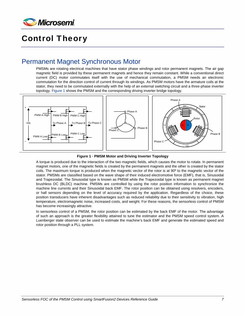
Permanent Magnet Synchronous Motor PMSMs are rotating electrical machines that have stator phase windings and rotor permanent magnets. The air gap magnetic field is provided by these permanent magnets and hence they remain constant. While a conventional direct current (DC) motor commutates itself with the use of mechanical commutation, a PMSM needs an electronic commutation for the direction control of current through its windings. As PMSM motors have the armature coils at the stator, they need to be commutated externally with the help of an external switching circuit and a three-phase inverter topology. Figure 1 shows the PMSM and the corresponding driving inverter bridge topology.
Vdc
PWM A High
PWM A LowPWM B Low
PWM B High PWM C High
PWM C Low
To Phase A
+
_
To Phase B To Phase C
Phase C
Phase A
Phase BN S
010
100
001
101
011
Phase C
Phase B
Rotor
Phase A
Stator
110
Figure 1 · PMSM Motor and Driving Inverter Topology
A torque is produced due to the interaction of the two magnetic fields, which causes the motor to rotate. In permanent magnet motors, one of the magnetic fields is created by the permanent magnets and the other is created by the stator coils. The maximum torque is produced when the magnetic vector of the rotor is at 90º to the magnetic vector of the stator. PMSMs are classified based on the wave shape of their induced electromotive force (EMF), that is, Sinusoidal and Trapezoidal. The Sinusoidal type is known as PMSM while the Trapezoidal type is known as permanent magnet brushless DC (BLDC) machine. PMSMs are controlled by using the rotor position information to synchronize the machine line currents and their Sinusoidal back EMF. The rotor position can be obtained using resolvers, encoders, or hall sensors depending on the level of accuracy required by the application. Regardless of the choice, these position transducers have inherent disadvantages such as reduced reliability due to their sensitivity to vibration, high temperature, electromagnetic noise, increased costs, and weight. For these reasons, the sensorless control of PMSM has become increasingly attractive. In sensorless control of a PMSM, the rotor position can be estimated by the back EMF of the motor. The advantage of such an approach is the greater flexibility attained to tune the estimator and the PMSM speed control system. A Luenberger state observer can be used to estimate the machine’s back EMF and generate the estimated speed and rotor position through a PLL system.
Sensorless FOC of the PMSM Control using SmartFusion2 Devices Reference Guide 7
Control Theory
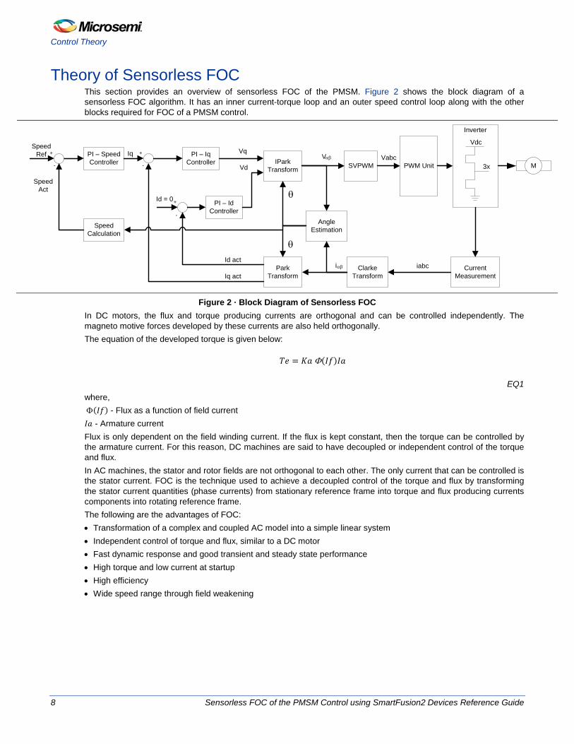
Theory of Sensorless FOC This section provides an overview of sensorless FOC of the PMSM. Figure 2 shows the block diagram of a sensorless FOC algorithm. It has an inner current-torque loop and an outer speed control loop along with the other blocks required for FOC of a PMSM control.
Vdc
3x
Current Measurement
Clarke Transform
Park Transform
Angle Estimation
IPark Transform SVPWM PWM Unit
i
Vabc
iabc
PI – Iq Controller
PI – IdController
PI – Speed Controller
Id = 0
Id act
Iq act
Iq
Speed Calculation
Speed Ref
Inverter
Vq
Vd M
+ +
+
-
--
αβ
Vαβ
θ
θ
Speed Act
Figure 2 · Block Diagram of Sensorless FOC
In DC motors, the flux and torque producing currents are orthogonal and can be controlled independently. The magneto motive forces developed by these currents are also held orthogonally. The equation of the developed torque is given below:
𝑇𝑒 = 𝐾𝑎 Φ(𝐼𝑓)𝐼𝑎
EQ1 where, Φ(𝐼𝑓) - Flux as a function of field current 𝐼𝑎 - Armature current Flux is only dependent on the field winding current. If the flux is kept constant, then the torque can be controlled by the armature current. For this reason, DC machines are said to have decoupled or independent control of the torque and flux. In AC machines, the stator and rotor fields are not orthogonal to each other. The only current that can be controlled is the stator current. FOC is the technique used to achieve a decoupled control of the torque and flux by transforming the stator current quantities (phase currents) from stationary reference frame into torque and flux producing currents components into rotating reference frame. The following are the advantages of FOC: • Transformation of a complex and coupled AC model into a simple linear system • Independent control of torque and flux, similar to a DC motor • Fast dynamic response and good transient and steady state performance • High torque and low current at startup • High efficiency • Wide speed range through field weakening
8 Sensorless FOC of the PMSM Control using SmartFusion2 Devices Reference Guide
FOC Algorithm Blocks
FOC Algorithm Blocks The following sub-sections describes each of the blocks required for a successful implementation of FOC system: • Current Measurement • Clarke Transformation • Inverse Clarke Transformation • Park Transformation • Inverse Park Transformation • Space Vector Pulse Width Modulation • PWM Generation • Angle Calculation • Speed Calculation • Open Loop Mode • Ramp Function
Current Measurement The current measurement block interfaces with an analog to digital converter (ADC) that accurately measures the current at periodic intervals. The current measurement block triggers the start of ADC conversion process and collects sampled results from up to six channels. It provides the following features: • Triggers ADC start conversion (sampling) process • Supports dual triggering of samples • Collects data upto six channels and arranges them in 14- and/or 12-bit format • Generates the results ready signal for each individual channel when the results are ready • Protects results if the results are not read by the host interface by ignoring subsequent samples • Supports Power saving modes in external ADC devices • Supports Auto scan mode The phase currents are typically measured from the current measurement block at 50 µs interval.
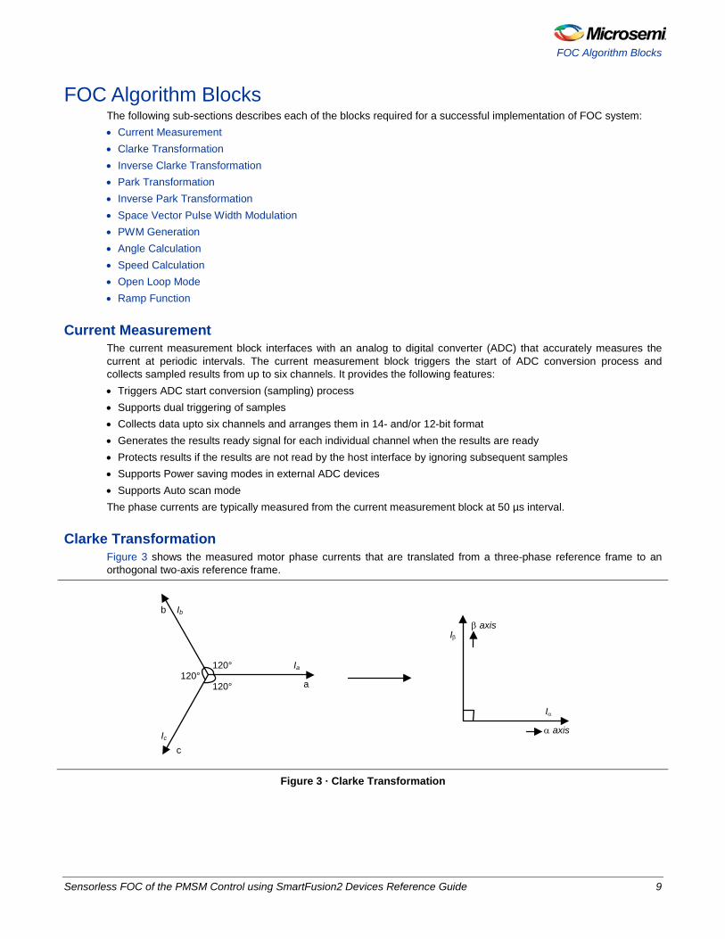
Clarke Transformation Figure 3 shows the measured motor phase currents that are translated from a three-phase reference frame to an orthogonal two-axis reference frame.
120°120°
120° a
b
c
Ia
Ib
Ic
Iα
Iβ
α axis
β axis
Figure 3 · Clarke Transformation
Sensorless FOC of the PMSM Control using SmartFusion2 Devices Reference Guide 9
Control Theory
The transformation is expressed in the following equations:
𝐼𝛼 = 𝐼𝑎
EQ2
𝐼𝛽 =1√3
(𝐼𝑎 + 2𝐼𝑏)
EQ3 where, 𝐼𝑎 and 𝐼𝑏 are phase quantities 𝐼𝛼 and 𝐼𝛽 are stationary orthogonal reference frame quantities
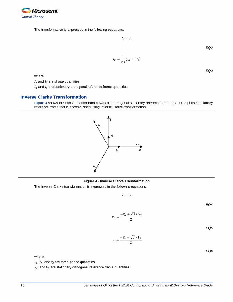
Inverse Clarke Transformation Figure 4 shows the transformation from a two-axis orthogonal stationary reference frame to a three-phase stationary reference frame that is accomplished using Inverse Clarke transformation.
α
β
Va
Vb
Vc
Vβ
Vα
Figure 4 · Inverse Clarke Transformation
The Inverse Clarke transformation is expressed in the following equations:
𝑉𝑎 = 𝑉𝛼
EQ4
𝑉𝑏 =−𝑉𝛼 + √3 ∗ 𝑉𝛽
2
EQ5
𝑉𝑐 =−𝑉𝛼 − √3 ∗ 𝑉𝛽
2
EQ6 where, 𝑉𝑎, 𝑉𝑏, and 𝑉𝑐 are three-phase quantities 𝑉𝛼, and 𝑉𝛽 are stationary orthogonal reference frame quantities
10 Sensorless FOC of the PMSM Control using SmartFusion2 Devices Reference Guide
FOC Algorithm Blocks
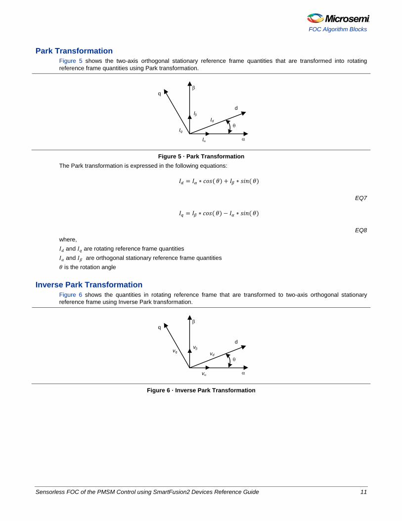
Park Transformation Figure 5 shows the two-axis orthogonal stationary reference frame quantities that are transformed into rotating reference frame quantities using Park transformation.
α
βq
Iβ
Iq
Iα
Id
d
θ
Figure 5 · Park Transformation
The Park transformation is expressed in the following equations:
𝐼𝑑 = 𝐼𝛼 ∗ 𝑐𝑜𝑠(𝜃) + 𝐼𝛽 ∗ 𝑠𝑖𝑛(𝜃)
EQ7
𝐼𝑞 = 𝐼𝛽 ∗ 𝑐𝑜𝑠(𝜃) − 𝐼𝛼 ∗ 𝑠𝑖𝑛(𝜃)
EQ8 where, 𝐼𝑑 and 𝐼𝑞 are rotating reference frame quantities 𝐼𝛼 and 𝐼𝛽 are orthogonal stationary reference frame quantities 𝜃 is the rotation angle
Inverse Park Transformation Figure 6 shows the quantities in rotating reference frame that are transformed to two-axis orthogonal stationary reference frame using Inverse Park transformation.
α
βq
vβvq
vα
vd
d
θ
Figure 6 · Inverse Park Transformation
Sensorless FOC of the PMSM Control using SmartFusion2 Devices Reference Guide 11
Control Theory
The Inverse Park transformation is expressed in the following equations:
𝑉𝛼 = 𝑉𝑑 ∗ 𝑐𝑜𝑠(𝜃) − 𝑉𝑞 ∗ 𝑠𝑖𝑛(𝜃)
EQ9
𝑉𝛽 = 𝑉𝑞 ∗ 𝑐𝑜𝑠(𝜃) + 𝑉𝑑 ∗ 𝑠𝑖𝑛(𝜃)
EQ10 where, 𝑉𝛼 and 𝑉𝛽 are orthogonal stationary reference frame quantities 𝑉𝑑 and 𝑉𝑞 are rotating reference frame quantities 𝜃 is the rotation angle
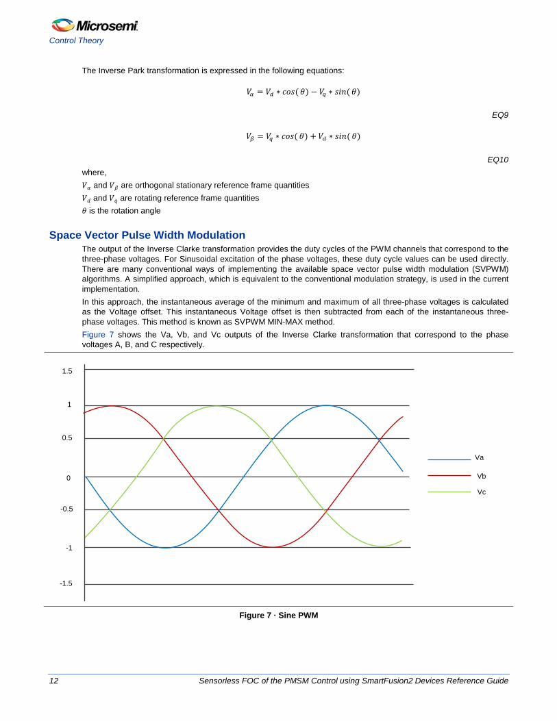
Space Vector Pulse Width Modulation The output of the Inverse Clarke transformation provides the duty cycles of the PWM channels that correspond to the three-phase voltages. For Sinusoidal excitation of the phase voltages, these duty cycle values can be used directly. There are many conventional ways of implementing the available space vector pulse width modulation (SVPWM) algorithms. A simplified approach, which is equivalent to the conventional modulation strategy, is used in the current implementation. In this approach, the instantaneous average of the minimum and maximum of all three-phase voltages is calculated as the Voltage offset. This instantaneous Voltage offset is then subtracted from each of the instantaneous three-phase voltages. This method is known as SVPWM MIN-MAX method. Figure 7 shows the Va, Vb, and Vc outputs of the Inverse Clarke transformation that correspond to the phase voltages A, B, and C respectively.
Vc
Va
1.5
1
0.5
0
-0.5
-1
-1.5
Vb
Figure 7 · Sine PWM
12 Sensorless FOC of the PMSM Control using SmartFusion2 Devices Reference Guide
FOC Algorithm Blocks
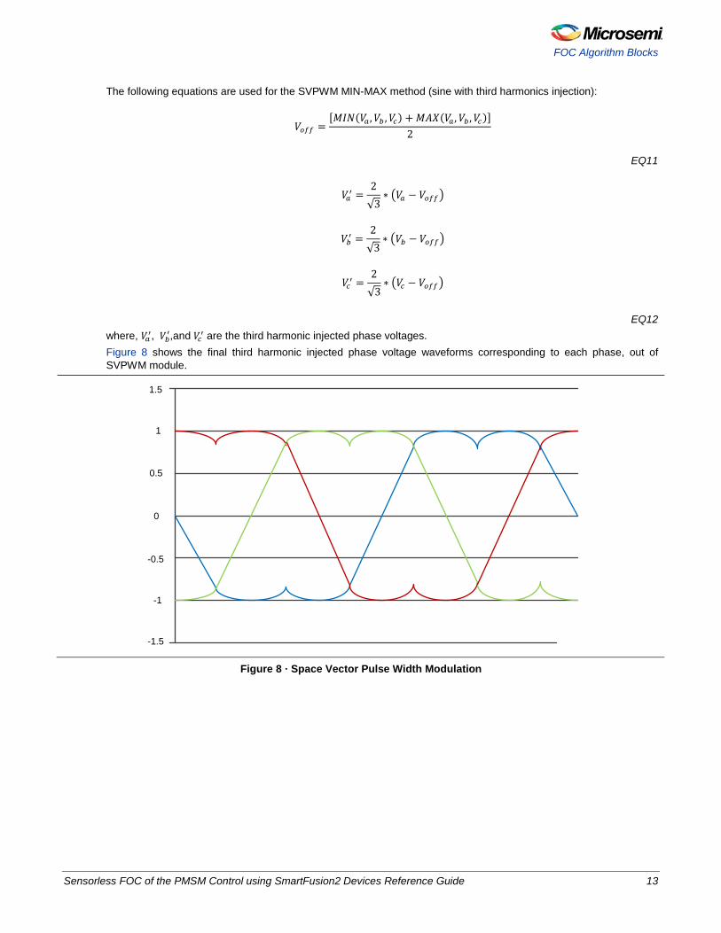
The following equations are used for the SVPWM MIN-MAX method (sine with third harmonics injection):
𝑉𝑜𝑓𝑓 =[𝑀𝐼𝑁(𝑉𝑎 ,𝑉𝑏 ,𝑉𝑐) + 𝑀𝐴𝑋(𝑉𝑎 ,𝑉𝑏 ,𝑉𝑐)]
2
EQ11
𝑉𝑎′ =2√3
∗ �𝑉𝑎 − 𝑉𝑜𝑓𝑓�
𝑉𝑏′ =2√3
∗ �𝑉𝑏 − 𝑉𝑜𝑓𝑓�
𝑉𝑐′ =2√3
∗ �𝑉𝑐 − 𝑉𝑜𝑓𝑓�
EQ12 where, 𝑉𝑎′, 𝑉𝑏′,and 𝑉𝑐′ are the third harmonic injected phase voltages. Figure 8 shows the final third harmonic injected phase voltage waveforms corresponding to each phase, out of SVPWM module.
-1
-0.5
0
0.5
1
1.5
-1.5
Figure 8 · Space Vector Pulse Width Modulation
Sensorless FOC of the PMSM Control using SmartFusion2 Devices Reference Guide 13
Control Theory
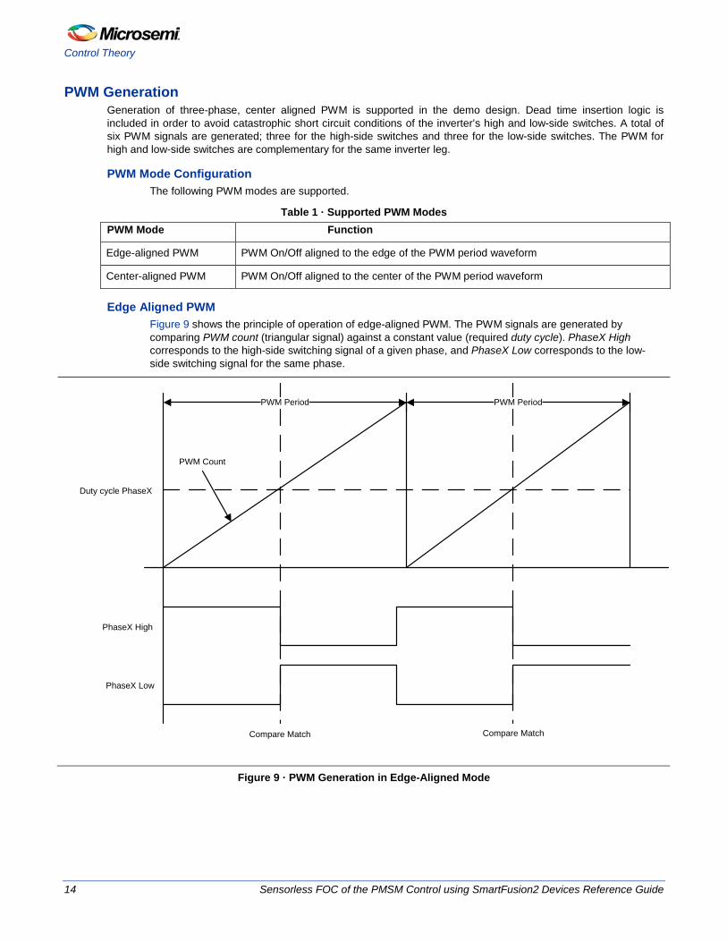
PWM Generation Generation of three-phase, center aligned PWM is supported in the demo design. Dead time insertion logic is included in order to avoid catastrophic short circuit conditions of the inverter’s high and low-side switches. A total of six PWM signals are generated; three for the high-side switches and three for the low-side switches. The PWM for high and low-side switches are complementary for the same inverter leg.
PWM Mode Configuration The following PWM modes are supported.
Table 1 · Supported PWM Modes PWM Mode Function
Edge-aligned PWM PWM On/Off aligned to the edge of the PWM period waveform
Center-aligned PWM PWM On/Off aligned to the center of the PWM period waveform
Edge Aligned PWM Figure 9 shows the principle of operation of edge-aligned PWM. The PWM signals are generated by comparing PWM count (triangular signal) against a constant value (required duty cycle). PhaseX High corresponds to the high-side switching signal of a given phase, and PhaseX Low corresponds to the low-side switching signal for the same phase.
PWM Period PWM Period
PWM Count
Duty cycle PhaseX
PhaseX High
PhaseX Low
Compare Match Compare Match
Figure 9 · PWM Generation in Edge-Aligned Mode
14 Sensorless FOC of the PMSM Control using SmartFusion2 Devices Reference Guide
FOC Algorithm Blocks
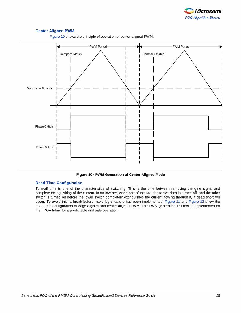
Center Aligned PWM Figure 10 shows the principle of operation of center-aligned PWM.
PWM Period PWM Period
Duty cycle PhaseX
PhaseX High
PhaseX Low
Compare Match Compare Match
Figure 10 · PWM Generation of Center-Aligned Mode
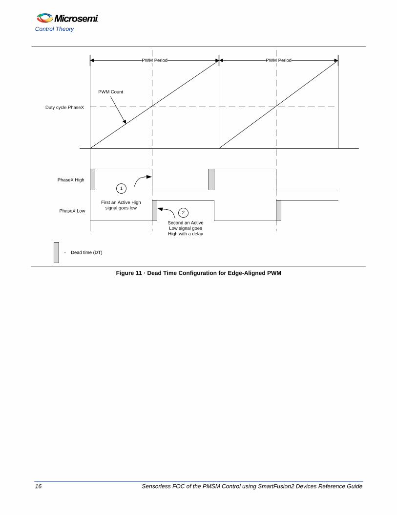
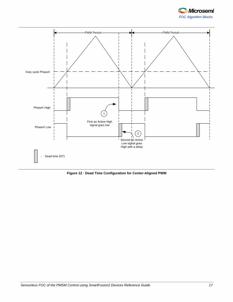
Dead Time Configuration Turn-off time is one of the characteristics of switching. This is the time between removing the gate signal and complete extinguishing of the current. In an inverter, when one of the two phase switches is turned off, and the other switch is turned on before the lower switch completely extinguishes the current flowing through it, a dead short will occur. To avoid this, a break before make logic feature has been implemented. Figure 11 and Figure 12 show the dead time configuration of edge-aligned and center-aligned PWM. The PWM generation IP block is implemented on the FPGA fabric for a predictable and safe operation.
Sensorless FOC of the PMSM Control using SmartFusion2 Devices Reference Guide 15
Control Theory
PWM Period PWM Period
PWM Count
Duty cycle PhaseX
PhaseX High
PhaseX Low
First an Active High signal goes low
Second an Active Low signal goes High with a delay
1
2
- Dead time (DT)
Figure 11 · Dead Time Configuration for Edge-Aligned PWM
16 Sensorless FOC of the PMSM Control using SmartFusion2 Devices Reference Guide
FOC Algorithm Blocks
PWM Period PWM Period
Duty cycle PhaseX
PhaseX High
PhaseX Low
Second an Active Low signal goes High with a delay
2
First an Active High signal goes low
1
- Dead time (DT)
Figure 12 · Dead Time Configuration for Center-Aligned PWM
Sensorless FOC of the PMSM Control using SmartFusion2 Devices Reference Guide 17
Control Theory
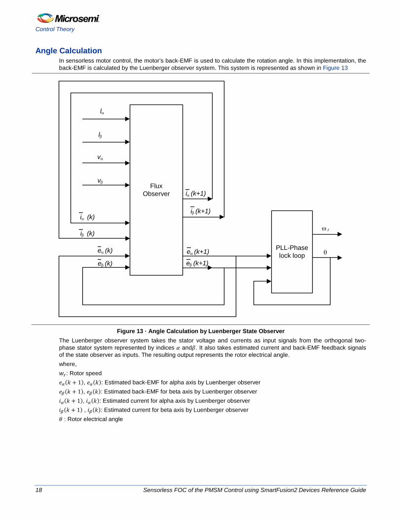
Angle Calculation In sensorless motor control, the motor’s back-EMF is used to calculate the rotation angle. In this implementation, the back-EMF is calculated by the Luenberger observer system. This system is represented as shown in Figure 13
Flux Observer
PLL-Phaselock loop
vα
vβ
lβ
lα
iβ (k)
iα (k+1)
iβ (k+1)
eα (k) eα (k+1)
eβ (k+1)
iα (k)
eβ (k)
θ
ω r
Figure 13 · Angle Calculation by Luenberger State Observer
The Luenberger observer system takes the stator voltage and currents as input signals from the orthogonal two-phase stator system represented by indices 𝛼 and𝛽. It also takes estimated current and back-EMF feedback signals of the state observer as inputs. The resulting output represents the rotor electrical angle. where, 𝑤𝑟: Rotor speed 𝑒𝛼(𝑘 + 1), 𝑒𝛼(𝑘): Estimated back-EMF for alpha axis by Luenberger observer 𝑒𝛽(𝑘 + 1), 𝑒𝛽(𝑘): Estimated back-EMF for beta axis by Luenberger observer 𝑖𝛼(𝑘 + 1), 𝑖𝛼(𝑘): Estimated current for alpha axis by Luenberger observer 𝑖𝛽(𝑘 + 1) , 𝑖𝛽(𝑘): Estimated current for beta axis by Luenberger observer 𝜃 : Rotor electrical angle
18 Sensorless FOC of the PMSM Control using SmartFusion2 Devices Reference Guide
FOC Algorithm Blocks
Speed Calculation The rotor angle from the angle calculation module is given as input to the speed calculation module. The speed is computed every 50 µs. The speed calculation uses a low-pass filter to smoothen the rotor speed. The low-pass filter is represented by the following equation:
𝑌𝑘 = ((𝐶𝑜𝑒𝑓𝑓𝐴 ∗ 𝑟𝑜𝑡𝑜𝑟 𝑠𝑝𝑒𝑒𝑑) − (𝐶𝑜𝑒𝑓𝑓𝐵 ∗ 𝑌𝑘 − 1) + 𝑌𝑘 − 1)
EQ13 where, 𝑌𝑘: Output of low-pass filter 𝐶𝑜𝑒𝑓𝑓𝐴: Filter coefficient A 𝐶𝑜𝑒𝑓𝑓𝐵: Filter coefficient B 𝑌𝑘−1: Previous output of low-pass filter The rotor speed output from the low-pass filter is in radian/seconds. This speed value is converted into an RPM by the following equations:
𝜔 = 2𝜋𝑓
EQ14
𝑠𝑝𝑒𝑒𝑑 =120𝑓𝑝
EQ15 where, 𝑓: Electrical frequency of the rotor. 𝑝: Number of poles.
Open Loop Mode When the motor is started, there will not be any back-EMF. To generate sufficient back-EMF, the motor is started with a particular constant open-loop speed. During this period, the angle calculation block also runs to estimate the rotor angle. After certain period, the estimated angle and the open-loop angle match with a minimal offset. The motor can switch to closed loop after which the position is continuously estimated by the angle calculation block. The period of time in which the motor runs in an open-loop for the rotor electrical angle to match with the open-loop angle can be configured. This time period is referred as the Switch Time.
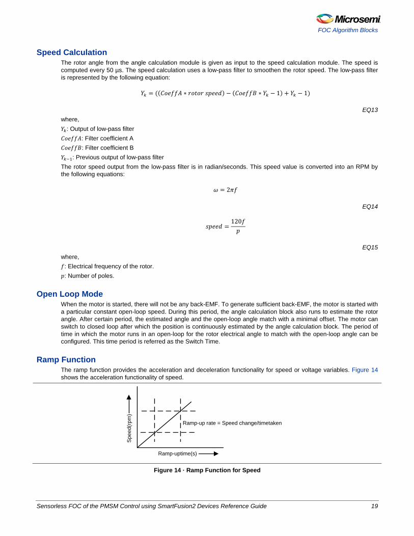
Ramp Function The ramp function provides the acceleration and deceleration functionality for speed or voltage variables. Figure 14 shows the acceleration functionality of speed.
Ramp-uptime(s)
Ramp-up rate = Speed change/timetaken
Spe
ed(r
pm)
Figure 14 · Ramp Function for Speed
Sensorless FOC of the PMSM Control using SmartFusion2 Devices Reference Guide 19
Control Theory
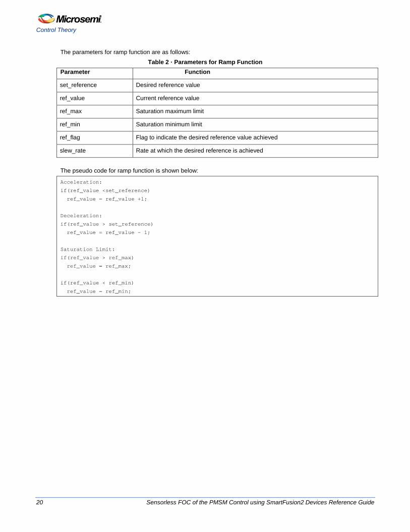
The parameters for ramp function are as follows: Table 2 · Parameters for Ramp Function
Parameter Function
set_reference Desired reference value
ref_value Current reference value
ref_max Saturation maximum limit
ref_min Saturation minimum limit
ref_flag Flag to indicate the desired reference value achieved
slew_rate Rate at which the desired reference is achieved
The pseudo code for ramp function is shown below:
Acceleration:
if(ref_value <set_reference)
ref_value = ref_value +1;
Deceleration:
if(ref_value > set_reference)
ref_value = ref_value – 1;
Saturation Limit:
if(ref_value > ref_max)
ref_value = ref_max;
if(ref_value < ref_min)
ref_value = ref_min;
20 Sensorless FOC of the PMSM Control using SmartFusion2 Devices Reference Guide
Sensorless FOC
Software Design
Sensorless FOC In Sensorless FOC implementation, the initial rotor position of the motor is unknown. The back-EMF is zero when the rotor is stationary. The motor initially runs in open-loop and after a predefined interval (switch time) it switches to closed-loop. To run the motor in open-loop, you need rotor position and applied voltage. The initial rotor position angle and applied voltage are computed using V/F method. In open-loop, the calculated rotor position angle and applied voltage are applied smoothly by ramp function to avoid any sudden jerks in the motor while incrementing/decrementing angle and applied voltage. The rotor position is estimated in parallel by Luenberger method while the motor is running in open-loop. After the Switch Time, the motor continues to spin in closed-loop with angle estimated from the Luenberger observer as a reference. For angle estimation to work correctly, accurate current measurement is a key requirement. The phase current measurements are synchronized with PWM signals and measurements are taken every mid-period match of PWM. These currents are subsequently converted to alpha and beta quantities. The alpha and beta quantities of currents and voltages are fed to angle estimation block along with previous estimated angle. The angle estimation block estimates 𝛼 and 𝛽 quantities of back-EMF by Luenberger observer equations. These back-EMFs are fed to PLL to compute the actual rotor position of motor. This sensorless FOC system controls with inner torque with outer speed control. The reference speed can be ramped up or ramped down from actual speed using ramp function for smooth transition. The torque and speed PI blocks can be tuned by configurable Kp and Ki parameters. Space vector modulation (SVM) method is used to add fundamental and third harmonic phase voltages. The SVM voltage is converted into PWM by SVPWM block and is fed to the core PWM block. The complete algorithm runs at every mid period match of PWM.
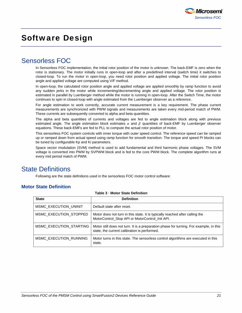
State Definitions Following are the state definitions used in the sensorless FOC motor control software:
Motor State Definition Table 3 · Motor State Definition
State Definition
MSMC_EXECUTION_UNINIT Default state after reset.
MSMC_EXECUTION_STOPPED Motor does not turn in this state. It is typically reached after calling the MotorControl_Stop API or MotorControl_Init API.
MSMC_EXECUTION_STARTING Motor still does not turn. It is a preparation phase for turning. For example, in this state, the current calibration is performed.
MSMC_EXECUTION_RUNNING Motor turns in this state. The sensorless control algorithms are executed in this state.
Sensorless FOC of the PMSM Control using SmartFusion2 Devices Reference Guide 21
Software Design
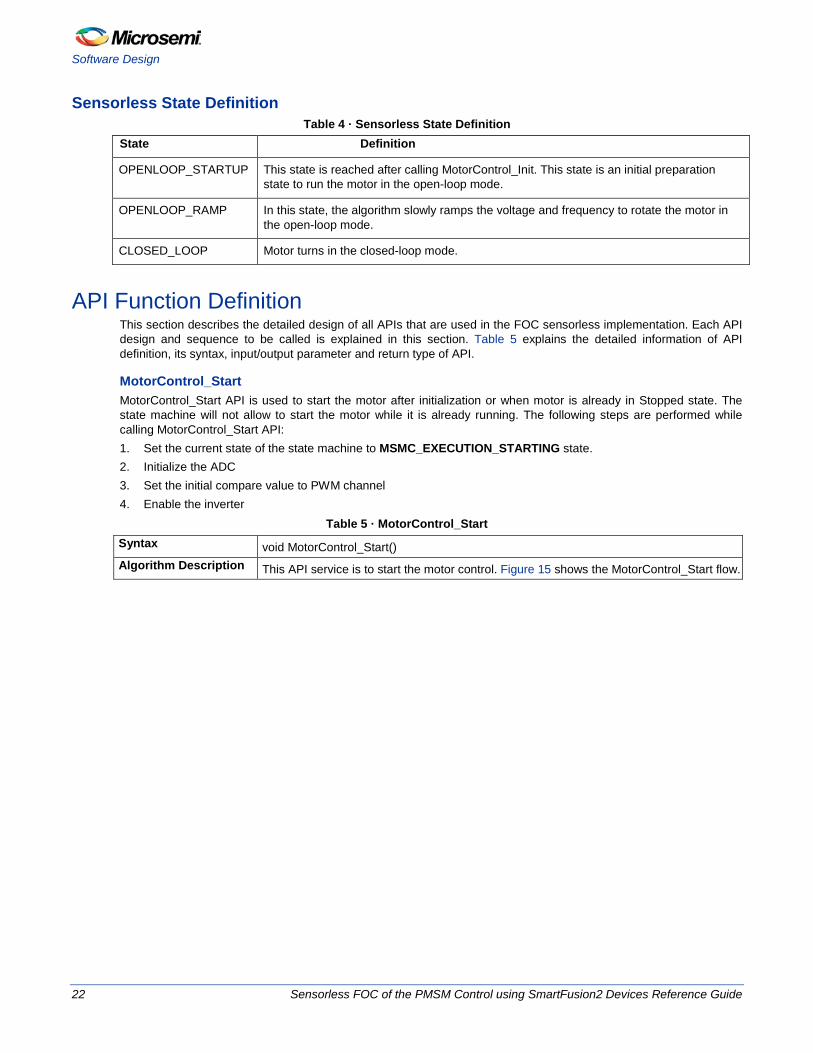
Sensorless State Definition Table 4 · Sensorless State Definition
State Definition
OPENLOOP_STARTUP This state is reached after calling MotorControl_Init. This state is an initial preparation state to run the motor in the open-loop mode.
OPENLOOP_RAMP In this state, the algorithm slowly ramps the voltage and frequency to rotate the motor in the open-loop mode.
CLOSED_LOOP Motor turns in the closed-loop mode.
API Function Definition This section describes the detailed design of all APIs that are used in the FOC sensorless implementation. Each API design and sequence to be called is explained in this section. Table 5 explains the detailed information of API definition, its syntax, input/output parameter and return type of API.
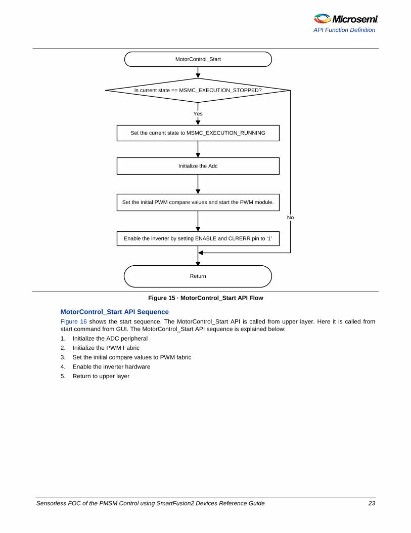
MotorControl_Start MotorControl_Start API is used to start the motor after initialization or when motor is already in Stopped state. The state machine will not allow to start the motor while it is already running. The following steps are performed while calling MotorControl_Start API: 1. Set the current state of the state machine to MSMC_EXECUTION_STARTING state. 2. Initialize the ADC 3. Set the initial compare value to PWM channel 4. Enable the inverter
Table 5 · MotorControl_Start Syntax void MotorControl_Start() Algorithm Description This API service is to start the motor control. Figure 15 shows the MotorControl_Start flow.
22 Sensorless FOC of the PMSM Control using SmartFusion2 Devices Reference Guide
API Function Definition
MotorControl_Start
Set the current state to MSMC_EXECUTION_RUNNING
Initialize the Adc
Set the initial PWM compare values and start the PWM module.
Return
Is current state == MSMC_EXECUTION_STOPPED?
Enable the inverter by setting ENABLE and CLRERR pin to ‘1’
No
Yes
Figure 15 · MotorControl_Start API Flow
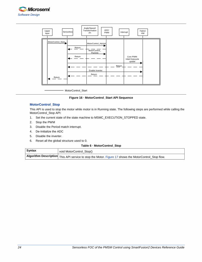
MotorControl_Start API Sequence Figure 16 shows the start sequence. The MotorControl_Start API is called from upper layer. Here it is called from start command from GUI. The MotorControl_Start API sequence is explained below: 1. Initialize the ADC peripheral 2. Initialize the PWM Fabric 3. Set the initial compare values to PWM fabric 4. Enable the inverter hardware 5. Return to upper layer
Sensorless FOC of the PMSM Control using SmartFusion2 Devices Reference Guide 23
Software Design
Upper layer
Fabric/HW
Angle/Speed/Transformation
/PIADC/PWM InterruptSensorless
MotorControl_Start
MotorControl_Start
Return
Return
Return
Return
Return
MotorControl_AdcInit
Core PWM:Intial Dutycycle
update
Enable Inverter
MotorControl_PwmInit
Figure 16 · MotorControl_Start API Sequence
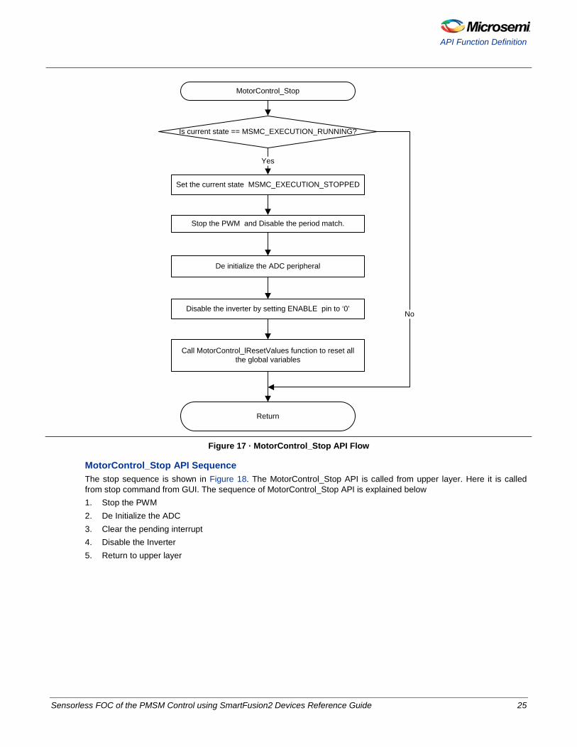
MotorControl_Stop This API is used to stop the motor while motor is in Running state. The following steps are performed while calling the MotorControl_Stop API: 1. Set the current state of the state machine to MSMC_EXECUTION_STOPPED state. 2. Stop the PWM 3. Disable the Period match interrupt. 4. De-Initialize the ADC 5. Disable the inverter. 6. Reset all the global structure used to 0.
Table 6 · MotorControl_Stop Syntax void MotorControl_Stop() Algorithm Description This API service to stop the Motor. Figure 17 shows the MotorControl_Stop flow.
24 Sensorless FOC of the PMSM Control using SmartFusion2 Devices Reference Guide
API Function Definition
MotorControl_Stop
Set the current state MSMC_EXECUTION_STOPPED
Stop the PWM and Disable the period match.
De initialize the ADC peripheral
Return
Yes
Is current state == MSMC_EXECUTION_RUNNING?
Disable the inverter by setting ENABLE pin to ‘0’
Call MotorControl_lResetValues function to reset all the global variables
No
Figure 17 · MotorControl_Stop API Flow
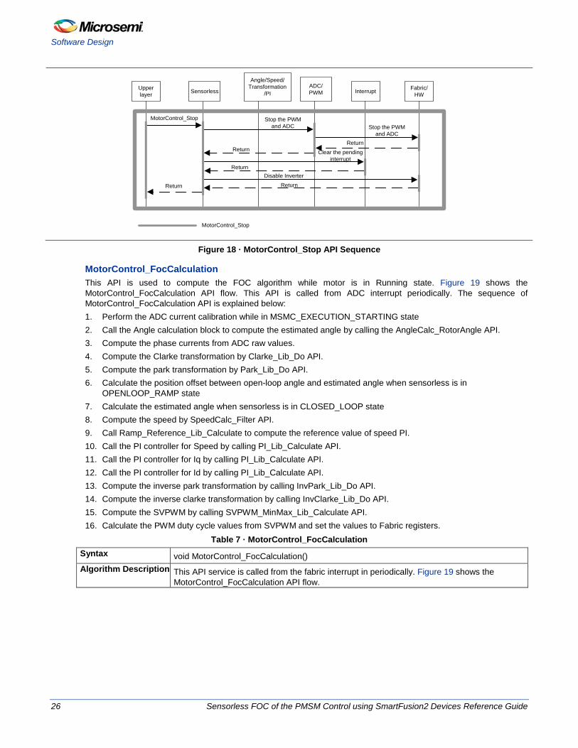
MotorControl_Stop API Sequence The stop sequence is shown in Figure 18. The MotorControl_Stop API is called from upper layer. Here it is called from stop command from GUI. The sequence of MotorControl_Stop API is explained below 1. Stop the PWM 2. De Initialize the ADC 3. Clear the pending interrupt 4. Disable the Inverter 5. Return to upper layer
Sensorless FOC of the PMSM Control using SmartFusion2 Devices Reference Guide 25
Software Design
Upper layer
Fabric/HW
Angle/Speed/Transformation
/PIADC/PWM InterruptSensorless
MotorControl_Stop Stop the PWM and ADC Stop the PWM
and ADCReturn
Return Clear the pending interrupt
ReturnDisable Inverter
ReturnReturn
MotorControl_Stop
Figure 18 · MotorControl_Stop API Sequence
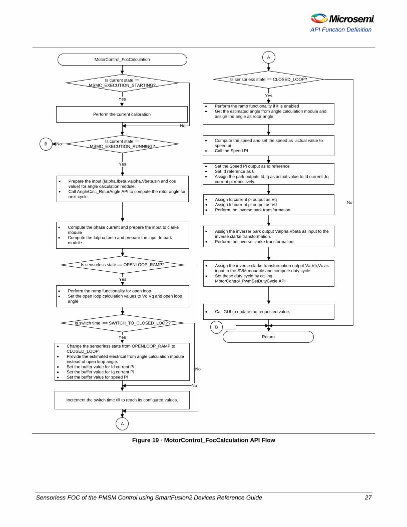
MotorControl_FocCalculation This API is used to compute the FOC algorithm while motor is in Running state. Figure 19 shows the MotorControl_FocCalculation API flow. This API is called from ADC interrupt periodically. The sequence of MotorControl_FocCalculation API is explained below: 1. Perform the ADC current calibration while in MSMC_EXECUTION_STARTING state 2. Call the Angle calculation block to compute the estimated angle by calling the AngleCalc_RotorAngle API. 3. Compute the phase currents from ADC raw values. 4. Compute the Clarke transformation by Clarke_Lib_Do API. 5. Compute the park transformation by Park_Lib_Do API. 6. Calculate the position offset between open-loop angle and estimated angle when sensorless is in
OPENLOOP_RAMP state 7. Calculate the estimated angle when sensorless is in CLOSED_LOOP state 8. Compute the speed by SpeedCalc_Filter API. 9. Call Ramp_Reference_Lib_Calculate to compute the reference value of speed PI. 10. Call the PI controller for Speed by calling PI_Lib_Calculate API. 11. Call the PI controller for Iq by calling PI_Lib_Calculate API. 12. Call the PI controller for Id by calling PI_Lib_Calculate API. 13. Compute the inverse park transformation by calling InvPark_Lib_Do API. 14. Compute the inverse clarke transformation by calling InvClarke_Lib_Do API. 15. Compute the SVPWM by calling SVPWM_MinMax_Lib_Calculate API. 16. Calculate the PWM duty cycle values from SVPWM and set the values to Fabric registers.
Table 7 · MotorControl_FocCalculation Syntax void MotorControl_FocCalculation() Algorithm Description This API service is called from the fabric interrupt in periodically. Figure 19 shows the
MotorControl_FocCalculation API flow.
26 Sensorless FOC of the PMSM Control using SmartFusion2 Devices Reference Guide
API Function Definition
MotorControl_FocCalculation
Perform the current calibration
• Compute the phase current and prepare the input to clarke module
• Compute the Ialpha,Ibeta and prepare the input to park module
Is current state == MSMC_EXECUTION_STARTING?
• Perform the ramp functionality for open loop• Set the open loop calculation values to Vd,Vq and open loop
angle
Is current state == MSMC_EXECUTION_RUNNING?
Is sensorless state == OPENLOOP_RAMP?
Yes
Yes
Is switch time == SWITCH_TO_CLOSED_LOOP?
• Change the sensorless state from OPENLOOP_RAMP to CLOSED_LOOP
• Provide the estimated electrical from angle calculation module instead of open loop angle.
• Set the buffer value for Id current Pi• Set the buffer value for Iq current Pi • Set the buffer value for speed Pi
A
Increment the switch time till to reach its configured values.
Yes
No
Yes
No
No
A
Is sensorless state == CLOSED_LOOP?
• Perform the ramp functionality if it is enabled• Get the estimated angle from angle calculation module and
assign the angle as rotor angle
• Compute the speed and set the speed as actual value to speed pi
• Call the Speed PI
• Set the Speed Pi output as Iq reference• Set Id reference as 0• Assign the park outputs Id,Iq as actual value to Id current ,Iq
current pi repectively.
• Assign Iq current pi output as Vq• Assign Id current pi output as Vd• Perform the inverse park transformation
• Assign the inverser park output Valpha,Vbeta as input to the inverse clarke transformation.
• Perform the inverse clarke transformation
• Assign the inverse clarke transformation output Va,Vb,Vc as input to the SVM moudule and compute duty cycle.
• Set these duty cycle by calling MotorControl_PwmSetDutyCycle API
• Prepare the input (Ialpha,Ibeta,Valpha,Vbeta,sin and cos value) for angle calculation module.
• Call AngleCalc_RotorAngle API to compute the rotor angle for next cycle.
Return
Yes
• Call GUI to update the requested value.
B
B
No
No
Figure 19 · MotorControl_FocCalculation API Flow
Sensorless FOC of the PMSM Control using SmartFusion2 Devices Reference Guide 27
Software Design
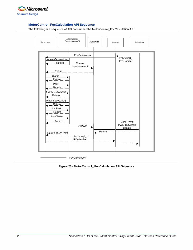
MotorControl_FocCalculation API Sequence The following is a sequence of API calls under the MotorControl_FocCalculation API.
Fabric/HW
Angle/Speed/Transformation/PI ADC/PWM Interrupt
FabricIrq0_IRQHandler
FocCalculation
Clarke
Park
Speed Calculation
Return
Return
Return
Return Current Measurement
Return
Angle Calculation
Pi for Speed,Id,Iq
Inv Park
Inv Clarke
Return
Return
Return
SVPWMCore PWM:
PWM Dutycycle update
ReturnReturn of SVPWMFabricIrq0_IRQHandler
Sensorless
FocCalculation
Figure 20 · MotorControl_ FocCalculation API Sequence
28 Sensorless FOC of the PMSM Control using SmartFusion2 Devices Reference Guide
Fabric Implementation
FPGA Fabric Design
This section describes implementation of sensorless FOC control of PMSM as implemented in the FPGA fabric hardware. The FPGA design is implemented using VHDL hardware description language and is designed to efficiently utilize SmartFusion2/IGLOO2 fabric resources. The following subsections describe the micro architecture of the top-level design.
Fabric Implementation
PI Controller
Inverse Park
Inverse Clark SVPWM
Park Clark
Angle Estimation
Sine Cos LUT
SpeedFilter
Iq_Ref
Id_Ref
Speed_Act
Speed_Ref
Id/Iq_Act
Scheduler000:Axis0001:Axis1010:Axis2011:Axis3100:Axis4101:Axis5
Id/Iq_Act
Axis Id
Axis Id
SpeedFilterSpeedFilterSpeedFilterSpeedFilterSpeedFilterPWM
SpeedFilterSpeedFilterSpeedFilterSpeedFilterSpeedFilterADC IF
PI SEL00:Speed01:Torqu10:FluxPI
TDM
MUX
TDM
MUX
TDM
MUX
T D M M U X
Timer50 us
50usAxis0 Axis1 Axis2 Axis3 Axis4 Axis5 Reserved Axis0
PWM Period
FOC Loop Time
6 us
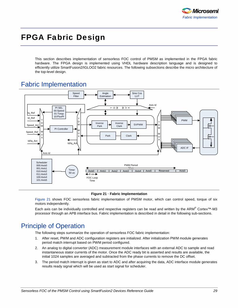
Figure 21 · Fabric Implementation Figure 21 shows FOC sensorless fabric implementation of PMSM motor, which can control speed, torque of six motors independently. Each axis can be individually controlled and respective registers can be read and written by the ARM® Cortex™-M3 processor through an APB interface bus. Fabric implementation is described in detail in the following sub-sections.
Principle of Operation The following steps summarize the operation of sensorless FOC fabric implementation: 1. After reset, PWM and ADC configuration registers are initialized. After initialization PWM module generates
period match interrupt based on PWM period configured. 2. An analog to digital converter (ADC) measurement module interfaces with an external ADC to sample and read
instantaneous stator currents of the motor. Once the ADC ready bit is asserted and results are available, the initial 1024 samples are averaged and subtracted from the phase currents to remove the DC offset.
3. The period match interrupt is given as start to ADC and after acquiring the data, ADC interface module generates results ready signal which will be used as start signal for scheduler.
Sensorless FOC of the PMSM Control using SmartFusion2 Devices Reference Guide 29
FPGA Fabric Design
4. The three-phase currents are converted to a two-axis coordinate system. This conversion provides Iα and Iβ from measured stator currents Ia, Ib, and Ic. This conversion is done by the Clark module which is instantiated in the CPICIP_TOP module.
5. The two-axis coordinate system is rotated to align with the rotor flux using the transformation angle that was computed at the previous iteration of the FOC control loop. This conversion provides the Id and Iq variables from Iα and Iβ. Id and Iq are the quadrature phase currents transformed into the rotating d-q coordinate system. For steady state conditions, Id and Iq are constants. This transformation is done by using Park Transformation module which is instantiated in CPICIP_TOP.
6. Difference error signals are computed using actual speed, Id, Iq, and corresponding reference values of each. • Speed reference is user driven that sets the desired speed of the motor • The Id reference controls rotor magnetizing flux • The Iq reference controls the torque output of the motor • All the error signals are driven to PI controllers which are instantiated in SPI_IDPI_IQPI module where a single
PI is used to do all the three operations in a time division multiplexed fashion • The outputs of Id PI and Iq PI will provide Vd and Vq which are voltage vectors that will be sent to motor
7. 𝑉𝑑 and 𝑉𝑞 are rotated back to stationary reference frame using the new angle. This calculation provides the next quadrature voltage values 𝑉𝑎 and 𝑉𝑏. This operation is done using Inverse park transformation module which is instantiated in CPICIP_TOP module.
8. A new transformation angle is calculated using the Vα, Vβ, Iα, and Iβ by the angle calculation block 9. Vα and Vβ are transformed back to three-phase voltages by the SVPWM module 10. The three-phase voltages are used to calculate the new PWM duty cycle values that generate the desired
voltage vector. This is implemented using Core3PhasePWM module. 11. After Step 10, the scheduler starts the next axis and repeats the above steps till all the six-axis are updated. CPICIP_TOP is a top file instantiating Clark, Park, Inverse Park, and Inverse Clark which uses single Multiply-Accumulate-Subtract (MAS) block and SPI_IDPI_IQPI is a top file which does all three PI operations using a single PI controller.
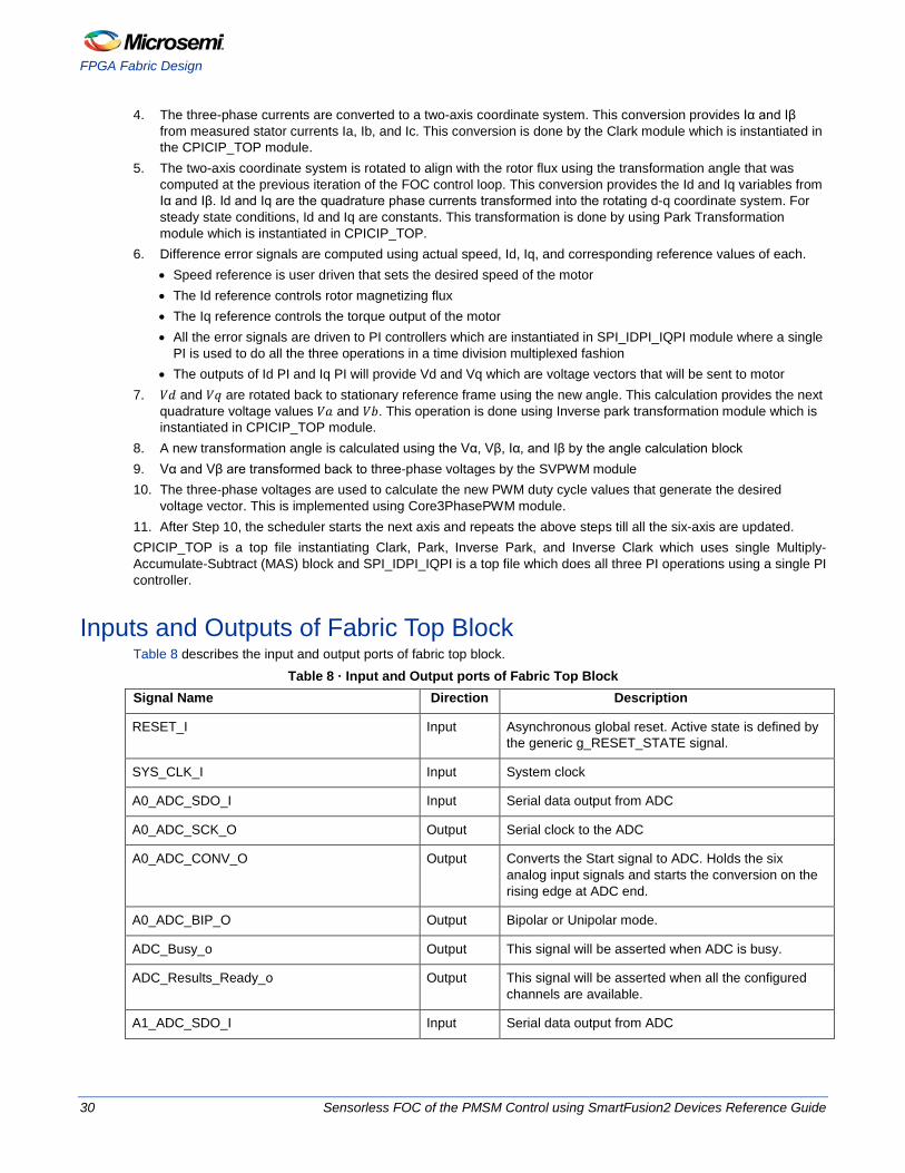
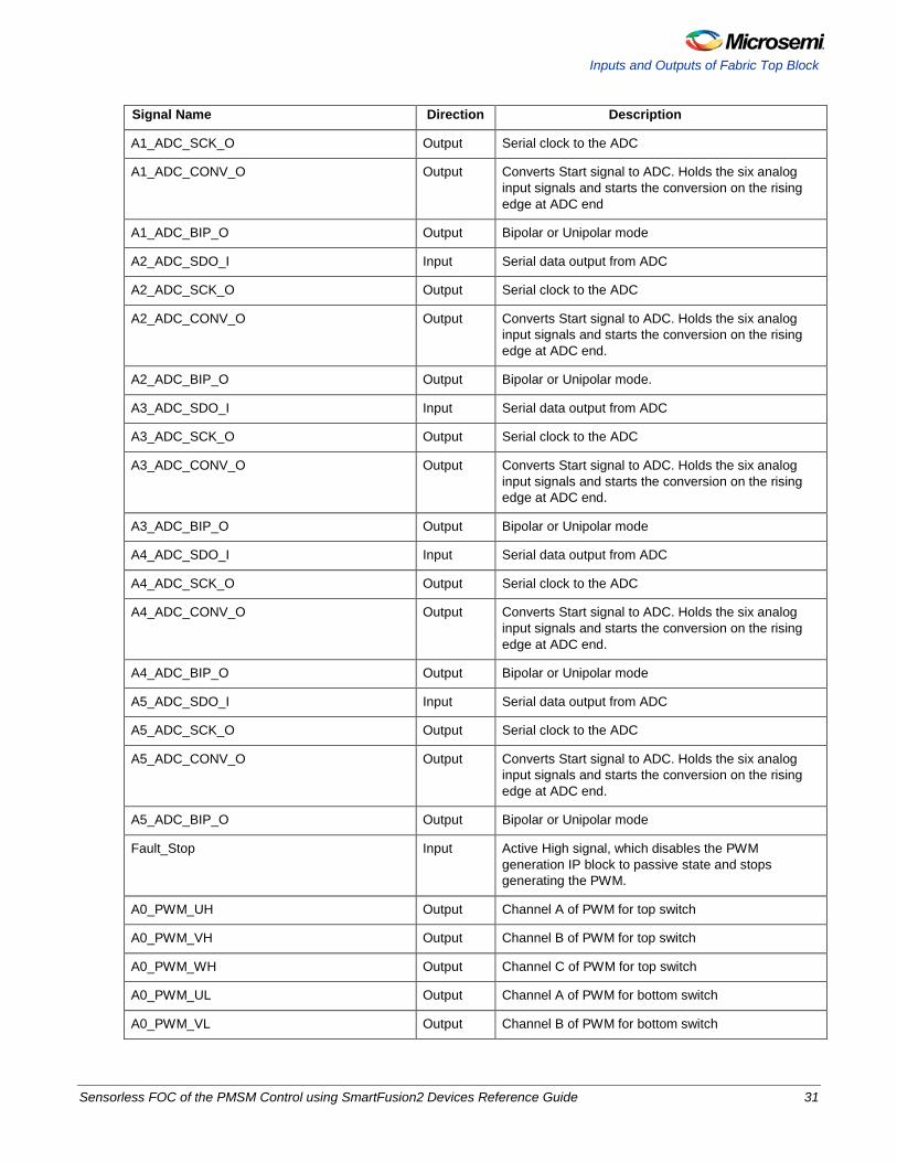
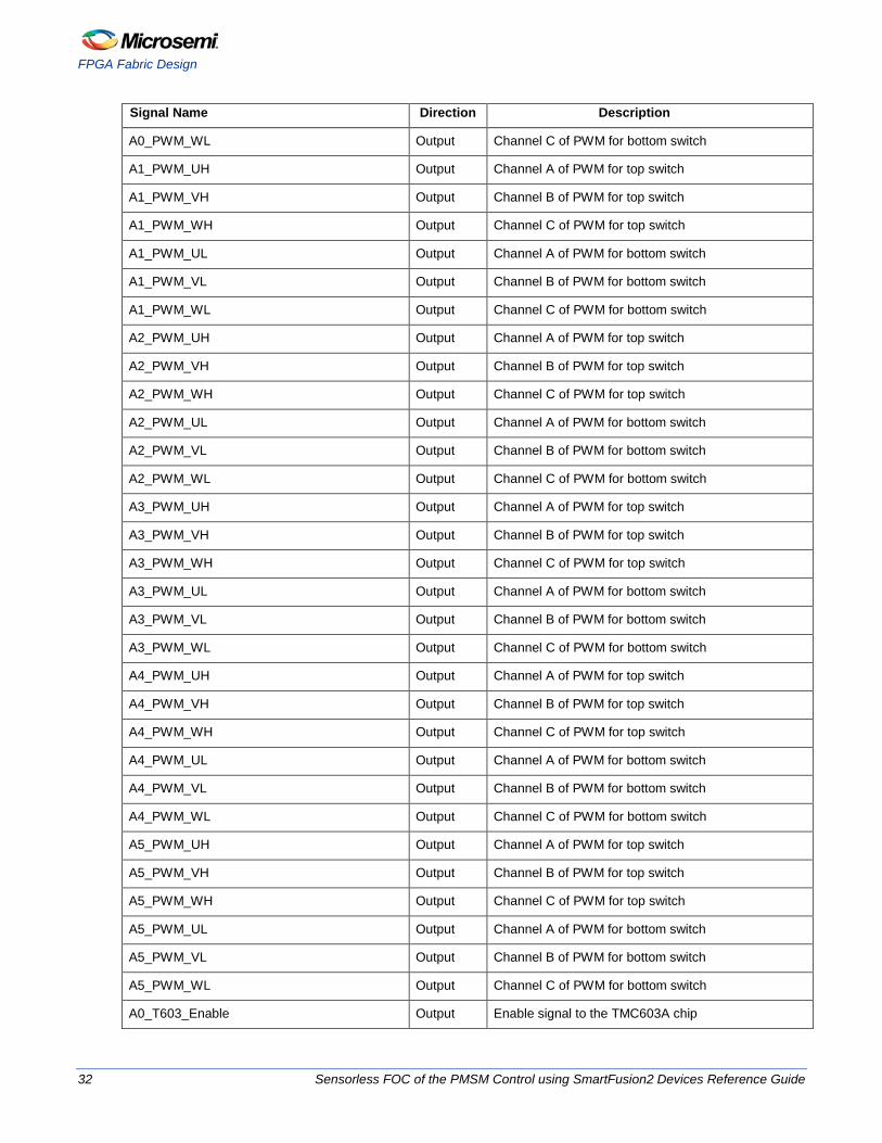
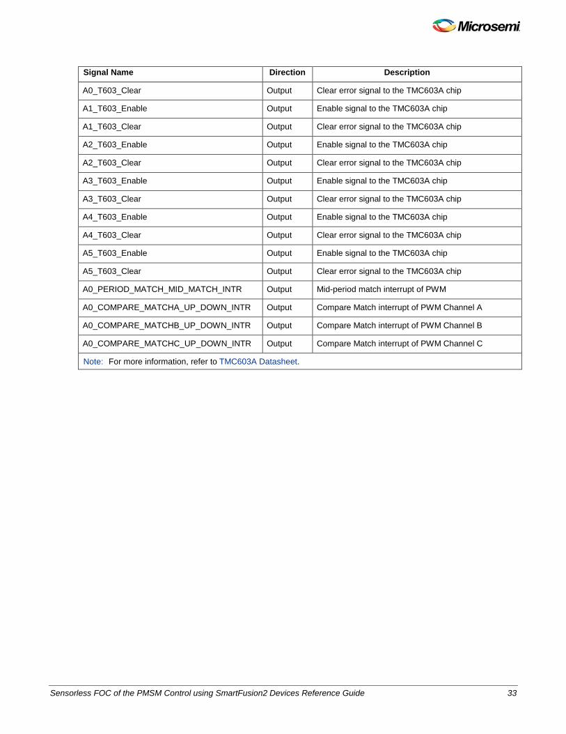
Inputs and Outputs of Fabric Top Block Table 8 describes the input and output ports of fabric top block.
Table 8 · Input and Output ports of Fabric Top Block Signal Name Direction Description
RESET_I Input Asynchronous global reset. Active state is defined by the generic g_RESET_STATE signal.
SYS_CLK_I Input System clock
A0_ADC_SDO_I Input Serial data output from ADC
A0_ADC_SCK_O Output Serial clock to the ADC
A0_ADC_CONV_O Output Converts the Start signal to ADC. Holds the six analog input signals and starts the conversion on the rising edge at ADC end.
A0_ADC_BIP_O Output Bipolar or Unipolar mode.
ADC_Busy_o Output This signal will be asserted when ADC is busy.
ADC_Results_Ready_o Output This signal will be asserted when all the configured channels are available.
A1_ADC_SDO_I Input Serial data output from ADC
30 Sensorless FOC of the PMSM Control using SmartFusion2 Devices Reference Guide
Inputs and Outputs of Fabric Top Block
Signal Name Direction Description
A1_ADC_SCK_O Output Serial clock to the ADC
A1_ADC_CONV_O Output Converts Start signal to ADC. Holds the six analog input signals and starts the conversion on the rising edge at ADC end
A1_ADC_BIP_O Output Bipolar or Unipolar mode
A2_ADC_SDO_I Input Serial data output from ADC
A2_ADC_SCK_O Output Serial clock to the ADC
A2_ADC_CONV_O Output Converts Start signal to ADC. Holds the six analog input signals and starts the conversion on the rising edge at ADC end.
A2_ADC_BIP_O Output Bipolar or Unipolar mode.
A3_ADC_SDO_I Input Serial data output from ADC
A3_ADC_SCK_O Output Serial clock to the ADC
A3_ADC_CONV_O Output Converts Start signal to ADC. Holds the six analog input signals and starts the conversion on the rising edge at ADC end.
A3_ADC_BIP_O Output Bipolar or Unipolar mode
A4_ADC_SDO_I Input Serial data output from ADC
A4_ADC_SCK_O Output Serial clock to the ADC
A4_ADC_CONV_O Output Converts Start signal to ADC. Holds the six analog input signals and starts the conversion on the rising edge at ADC end.
A4_ADC_BIP_O Output Bipolar or Unipolar mode
A5_ADC_SDO_I Input Serial data output from ADC
A5_ADC_SCK_O Output Serial clock to the ADC
A5_ADC_CONV_O Output Converts Start signal to ADC. Holds the six analog input signals and starts the conversion on the rising edge at ADC end.
A5_ADC_BIP_O Output Bipolar or Unipolar mode
Fault_Stop Input Active High signal, which disables the PWM generation IP block to passive state and stops generating the PWM.
A0_PWM_UH Output Channel A of PWM for top switch
A0_PWM_VH Output Channel B of PWM for top switch
A0_PWM_WH Output Channel C of PWM for top switch
A0_PWM_UL Output Channel A of PWM for bottom switch
A0_PWM_VL Output Channel B of PWM for bottom switch
Sensorless FOC of the PMSM Control using SmartFusion2 Devices Reference Guide 31
FPGA Fabric Design
Signal Name Direction Description
A0_PWM_WL Output Channel C of PWM for bottom switch
A1_PWM_UH Output Channel A of PWM for top switch
A1_PWM_VH Output Channel B of PWM for top switch
A1_PWM_WH Output Channel C of PWM for top switch
A1_PWM_UL Output Channel A of PWM for bottom switch
A1_PWM_VL Output Channel B of PWM for bottom switch
A1_PWM_WL Output Channel C of PWM for bottom switch
A2_PWM_UH Output Channel A of PWM for top switch
A2_PWM_VH Output Channel B of PWM for top switch
A2_PWM_WH Output Channel C of PWM for top switch
A2_PWM_UL Output Channel A of PWM for bottom switch
A2_PWM_VL Output Channel B of PWM for bottom switch
A2_PWM_WL Output Channel C of PWM for bottom switch
A3_PWM_UH Output Channel A of PWM for top switch
A3_PWM_VH Output Channel B of PWM for top switch
A3_PWM_WH Output Channel C of PWM for top switch
A3_PWM_UL Output Channel A of PWM for bottom switch
A3_PWM_VL Output Channel B of PWM for bottom switch
A3_PWM_WL Output Channel C of PWM for bottom switch
A4_PWM_UH Output Channel A of PWM for top switch
A4_PWM_VH Output Channel B of PWM for top switch
A4_PWM_WH Output Channel C of PWM for top switch
A4_PWM_UL Output Channel A of PWM for bottom switch
A4_PWM_VL Output Channel B of PWM for bottom switch
A4_PWM_WL Output Channel C of PWM for bottom switch
A5_PWM_UH Output Channel A of PWM for top switch
A5_PWM_VH Output Channel B of PWM for top switch
A5_PWM_WH Output Channel C of PWM for top switch
A5_PWM_UL Output Channel A of PWM for bottom switch
A5_PWM_VL Output Channel B of PWM for bottom switch
A5_PWM_WL Output Channel C of PWM for bottom switch
A0_T603_Enable Output Enable signal to the TMC603A chip
32 Sensorless FOC of the PMSM Control using SmartFusion2 Devices Reference Guide
Signal Name Direction Description
A0_T603_Clear Output Clear error signal to the TMC603A chip
A1_T603_Enable Output Enable signal to the TMC603A chip
A1_T603_Clear Output Clear error signal to the TMC603A chip
A2_T603_Enable Output Enable signal to the TMC603A chip
A2_T603_Clear Output Clear error signal to the TMC603A chip
A3_T603_Enable Output Enable signal to the TMC603A chip
A3_T603_Clear Output Clear error signal to the TMC603A chip
A4_T603_Enable Output Enable signal to the TMC603A chip
A4_T603_Clear Output Clear error signal to the TMC603A chip
A5_T603_Enable Output Enable signal to the TMC603A chip
A5_T603_Clear Output Clear error signal to the TMC603A chip
A0_PERIOD_MATCH_MID_MATCH_INTR Output Mid-period match interrupt of PWM
A0_COMPARE_MATCHA_UP_DOWN_INTR Output Compare Match interrupt of PWM Channel A
A0_COMPARE_MATCHB_UP_DOWN_INTR Output Compare Match interrupt of PWM Channel B
A0_COMPARE_MATCHC_UP_DOWN_INTR Output Compare Match interrupt of PWM Channel C
Note: For more information, refer to TMC603A Datasheet.
Sensorless FOC of the PMSM Control using SmartFusion2 Devices Reference Guide 33
FPGA Fabric Design
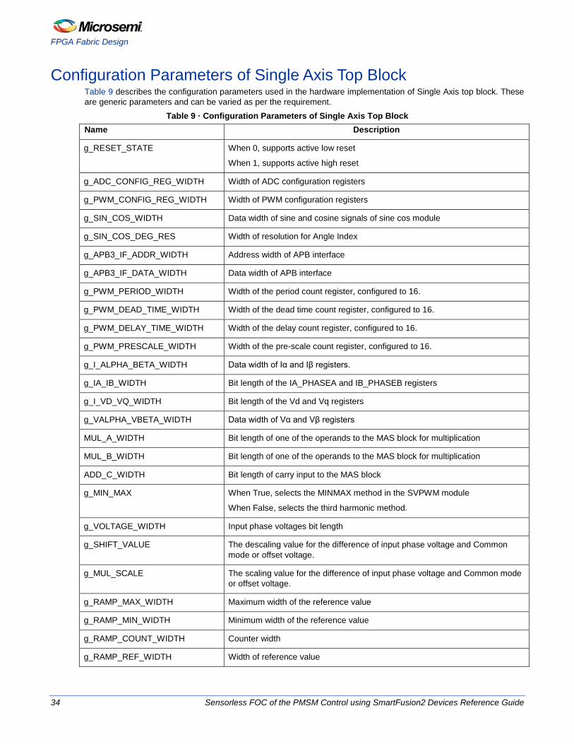
Configuration Parameters of Single Axis Top Block Table 9 describes the configuration parameters used in the hardware implementation of Single Axis top block. These are generic parameters and can be varied as per the requirement.
Table 9 · Configuration Parameters of Single Axis Top Block Name Description
g_RESET_STATE When 0, supports active low reset
When 1, supports active high reset
g_ADC_CONFIG_REG_WIDTH Width of ADC configuration registers
g_PWM_CONFIG_REG_WIDTH Width of PWM configuration registers
g_SIN_COS_WIDTH Data width of sine and cosine signals of sine cos module
g_SIN_COS_DEG_RES Width of resolution for Angle Index
g_APB3_IF_ADDR_WIDTH Address width of APB interface
g_APB3_IF_DATA_WIDTH Data width of APB interface
g_PWM_PERIOD_WIDTH Width of the period count register, configured to 16.
g_PWM_DEAD_TIME_WIDTH Width of the dead time count register, configured to 16.
g_PWM_DELAY_TIME_WIDTH Width of the delay count register, configured to 16.
g_PWM_PRESCALE_WIDTH Width of the pre-scale count register, configured to 16.
g_I_ALPHA_BETA_WIDTH Data width of Iα and Iβ registers.
g_IA_IB_WIDTH Bit length of the IA_PHASEA and IB_PHASEB registers
g_I_VD_VQ_WIDTH Bit length of the Vd and Vq registers
g_VALPHA_VBETA_WIDTH Data width of Vα and Vβ registers
MUL_A_WIDTH Bit length of one of the operands to the MAS block for multiplication
MUL_B_WIDTH Bit length of one of the operands to the MAS block for multiplication
ADD_C_WIDTH Bit length of carry input to the MAS block
g_MIN_MAX When True, selects the MINMAX method in the SVPWM module
When False, selects the third harmonic method.
g_VOLTAGE_WIDTH Input phase voltages bit length
g_SHIFT_VALUE The descaling value for the difference of input phase voltage and Common mode or offset voltage.
g_MUL_SCALE The scaling value for the difference of input phase voltage and Common mode or offset voltage.
g_RAMP_MAX_WIDTH Maximum width of the reference value
g_RAMP_MIN_WIDTH Minimum width of the reference value
g_RAMP_COUNT_WIDTH Counter width
g_RAMP_REF_WIDTH Width of reference value
34 Sensorless FOC of the PMSM Control using SmartFusion2 Devices Reference Guide
Name Description
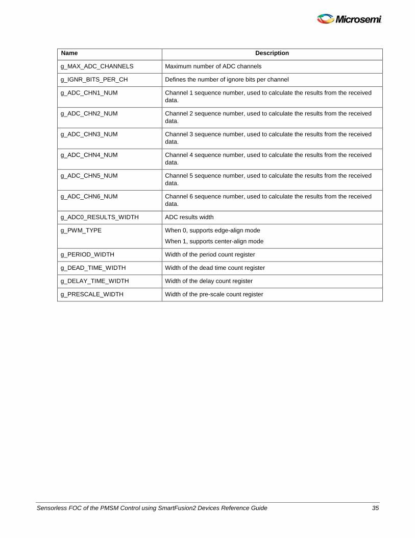
g_MAX_ADC_CHANNELS Maximum number of ADC channels
g_IGNR_BITS_PER_CH Defines the number of ignore bits per channel
g_ADC_CHN1_NUM Channel 1 sequence number, used to calculate the results from the received data.
g_ADC_CHN2_NUM Channel 2 sequence number, used to calculate the results from the received data.
g_ADC_CHN3_NUM Channel 3 sequence number, used to calculate the results from the received data.
g_ADC_CHN4_NUM Channel 4 sequence number, used to calculate the results from the received data.
g_ADC_CHN5_NUM Channel 5 sequence number, used to calculate the results from the received data.
g_ADC_CHN6_NUM Channel 6 sequence number, used to calculate the results from the received data.
g_ADC0_RESULTS_WIDTH ADC results width
g_PWM_TYPE When 0, supports edge-align mode
When 1, supports center-align mode
g_PERIOD_WIDTH Width of the period count register
g_DEAD_TIME_WIDTH Width of the dead time count register
g_DELAY_TIME_WIDTH Width of the delay count register
g_PRESCALE_WIDTH Width of the pre-scale count register
Sensorless FOC of the PMSM Control using SmartFusion2 Devices Reference Guide 35
FPGA Fabric Design
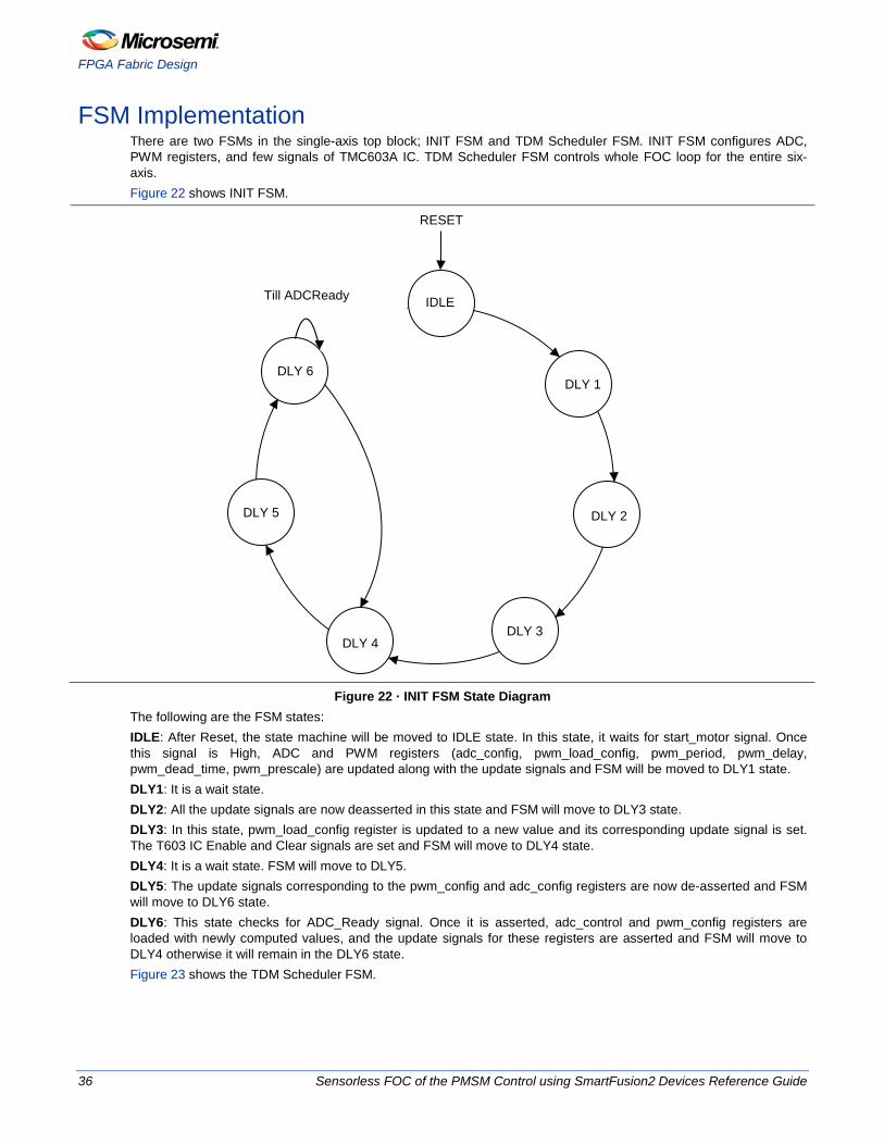
FSM Implementation There are two FSMs in the single-axis top block; INIT FSM and TDM Scheduler FSM. INIT FSM configures ADC, PWM registers, and few signals of TMC603A IC. TDM Scheduler FSM controls whole FOC loop for the entire six-axis. Figure 22 shows INIT FSM.
RESET
Till ADCReady IDLE
DLY 1
DLY 2
DLY 3DLY 4
DLY 5
DLY 6
Figure 22 · INIT FSM State Diagram
The following are the FSM states: IDLE: After Reset, the state machine will be moved to IDLE state. In this state, it waits for start_motor signal. Once this signal is High, ADC and PWM registers (adc_config, pwm_load_config, pwm_period, pwm_delay, pwm_dead_time, pwm_prescale) are updated along with the update signals and FSM will be moved to DLY1 state. DLY1: It is a wait state. DLY2: All the update signals are now deasserted in this state and FSM will move to DLY3 state. DLY3: In this state, pwm_load_config register is updated to a new value and its corresponding update signal is set. The T603 IC Enable and Clear signals are set and FSM will move to DLY4 state. DLY4: It is a wait state. FSM will move to DLY5. DLY5: The update signals corresponding to the pwm_config and adc_config registers are now de-asserted and FSM will move to DLY6 state. DLY6: This state checks for ADC_Ready signal. Once it is asserted, adc_control and pwm_config registers are loaded with newly computed values, and the update signals for these registers are asserted and FSM will move to DLY4 otherwise it will remain in the DLY6 state. Figure 23 shows the TDM Scheduler FSM.
36 Sensorless FOC of the PMSM Control using SmartFusion2 Devices Reference Guide
FSM Implementation
RESET
IDLE
STARTCALIB
STARTADC
RES 1
STARTADC
RES 2
STARTADC
RES 3
STARTMVS
VAMVS
VBMVS
VCMVS
WAITSTATE
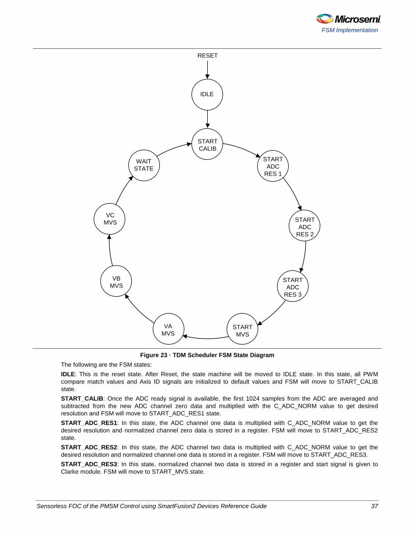
Figure 23 · TDM Scheduler FSM State Diagram
The following are the FSM states: IDLE: This is the reset state. After Reset, the state machine will be moved to IDLE state. In this state, all PWM compare match values and Axis ID signals are initialized to default values and FSM will move to START_CALIB state. START_CALIB: Once the ADC ready signal is available, the first 1024 samples from the ADC are averaged and subtracted from the new ADC channel zero data and multiplied with the C_ADC_NORM value to get desired resolution and FSM will move to START_ADC_RES1 state. START_ADC_RES1: In this state, the ADC channel one data is multiplied with C_ADC_NORM value to get the desired resolution and normalized channel zero data is stored in a register. FSM will move to START_ADC_RES2 state. START_ADC_RES2: In this state, the ADC channel two data is multiplied with C_ADC_NORM value to get the desired resolution and normalized channel one data is stored in a register. FSM will move to START_ADC_RES3. START_ADC_RES3: In this state, normalized channel two data is stored in a register and start signal is given to Clarke module. FSM will move to START_MVS state.
Sensorless FOC of the PMSM Control using SmartFusion2 Devices Reference Guide 37
FPGA Fabric Design
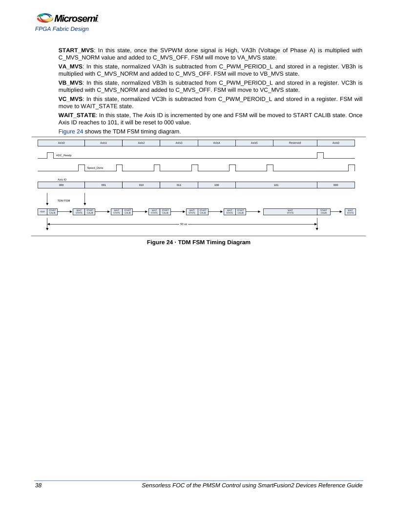
START_MVS: In this state, once the SVPWM done signal is High, VA3h (Voltage of Phase A) is multiplied with C_MVS_NORM value and added to C_MVS_OFF. FSM will move to VA_MVS state. VA_MVS: In this state, normalized VA3h is subtracted from C_PWM_PERIOD_L and stored in a register. VB3h is multiplied with C_MVS_NORM and added to C_MVS_OFF. FSM will move to VB_MVS state. VB_MVS: In this state, normalized VB3h is subtracted from C_PWM_PERIOD_L and stored in a register. VC3h is multiplied with C_MVS_NORM and added to C_MVS_OFF. FSM will move to VC_MVS state. VC_MVS: In this state, normalized VC3h is subtracted from C_PWM_PEROID_L and stored in a register. FSM will move to WAIT_STATE state. WAIT_STATE: In this state, The Axis ID is incremented by one and FSM will be moved to START CALIB state. Once Axis ID reaches to 101, it will be reset to 000 value. Figure 24 shows the TDM FSM timing diagram.
ADC_Ready
Speed_Done
TDM FSM
STARTCALIB
WAITSTATE
STARTCALIB
WAITSTATE
STARTCALIB
WAITSTATE
STARTCALIB
WAITSTATE
STARTCALIB
WAITSTATE
STARTCALIB
WAITSTATE
STARTCALIB
WAITSTATEIDLE
50 us
Axis0 Axis1 Axis2 Axis3 Axis4 Axis5 Reserved Axis0
000 001 010 011 100 101 000
Axis ID
Figure 24 · TDM FSM Timing Diagram
38 Sensorless FOC of the PMSM Control using SmartFusion2 Devices Reference Guide
FSM Implementation
Appendix
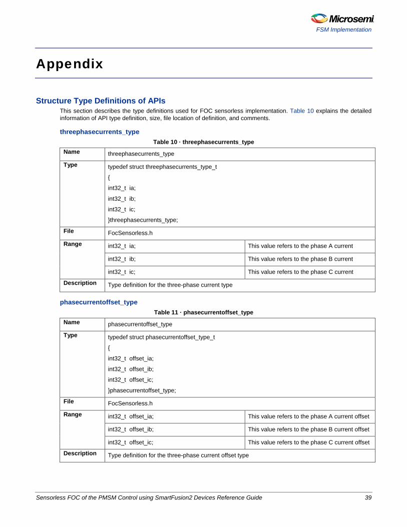
Structure Type Definitions of APIs This section describes the type definitions used for FOC sensorless implementation. Table 10 explains the detailed information of API type definition, size, file location of definition, and comments.
threephasecurrents_type Table 10 · threephasecurrents_type
Name threephasecurrents_type
Type typedef struct threephasecurrents_type_t
{
int32_t ia;
int32_t ib;
int32_t ic;
}threephasecurrents_type;
File FocSensorless.h
Range int32_t ia; This value refers to the phase A current
int32_t ib; This value refers to the phase B current
int32_t ic; This value refers to the phase C current
Description Type definition for the three-phase current type
phasecurrentoffset_type Table 11 · phasecurrentoffset_type
Name phasecurrentoffset_type
Type typedef struct phasecurrentoffset_type_t
{
int32_t offset_ia;
int32_t offset_ib;
int32_t offset_ic;
}phasecurrentoffset_type;
File FocSensorless.h
Range int32_t offset_ia; This value refers to the phase A current offset
int32_t offset_ib; This value refers to the phase B current offset
int32_t offset_ic; This value refers to the phase C current offset
Description Type definition for the three-phase current offset type
Sensorless FOC of the PMSM Control using SmartFusion2 Devices Reference Guide 39
Appendix
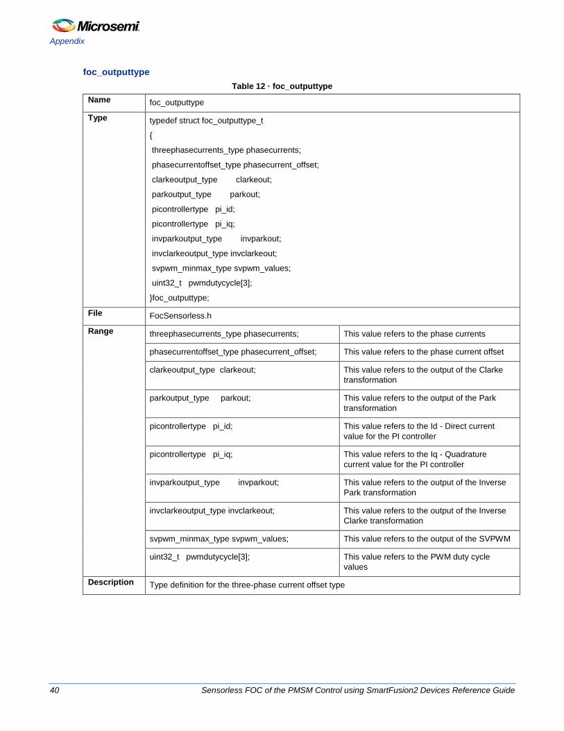
foc_outputtype Table 12 · foc_outputtype
Name foc_outputtype
Type typedef struct foc_outputtype_t
{
threephasecurrents_type phasecurrents;
phasecurrentoffset_type phasecurrent_offset;
clarkeoutput_type clarkeout;
parkoutput_type parkout;
picontrollertype pi_id;
picontrollertype pi_iq;
invparkoutput_type invparkout;
invclarkeoutput_type invclarkeout;
svpwm_minmax_type svpwm_values;
uint32_t pwmdutycycle[3];
}foc_outputtype;
File FocSensorless.h
Range threephasecurrents_type phasecurrents; This value refers to the phase currents
phasecurrentoffset_type phasecurrent_offset; This value refers to the phase current offset
clarkeoutput_type clarkeout; This value refers to the output of the Clarke transformation
parkoutput_type parkout; This value refers to the output of the Park transformation
picontrollertype pi_id; This value refers to the Id - Direct current value for the PI controller
picontrollertype pi_iq; This value refers to the Iq - Quadrature current value for the PI controller
invparkoutput_type invparkout; This value refers to the output of the Inverse Park transformation
invclarkeoutput_type invclarkeout; This value refers to the output of the Inverse Clarke transformation
svpwm_minmax_type svpwm_values; This value refers to the output of the SVPWM
uint32_t pwmdutycycle[3]; This value refers to the PWM duty cycle values
Description Type definition for the three-phase current offset type
40 Sensorless FOC of the PMSM Control using SmartFusion2 Devices Reference Guide
FSM Implementation
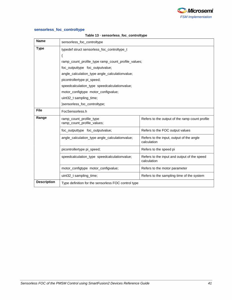
sensorless_foc_controltype Table 13 · sensorless_foc_controltype
Name sensorless_foc_controltype
Type typedef struct sensorless_foc_controltype_t
{
ramp_count_profile_type ramp_count_profile_values;
foc_outputtype foc_outputvalue;
angle_calculation_type angle_calculationvalue;
picontrollertype pi_speed;
speedcalculation_type speedcalculationvalue;
motor_configtype motor_configvalue;
uint32_t sampling_time;
}sensorless_foc_controltype;
File FocSensorless.h
Range ramp_count_profile_type ramp_count_profile_values;
Refers to the output of the ramp count profile
foc_outputtype foc_outputvalue; Refers to the FOC output values
angle_calculation_type angle_calculationvalue; Refers to the input, output of the angle calculation
picontrollertype pi_speed; Refers to the speed pi
speedcalculation_type speedcalculationvalue; Refers to the input and output of the speed calculation
motor_configtype motor_configvalue; Refers to the motor parameter
uint32_t sampling_time; Refers to the sampling time of the system
Description Type definition for the sensorless FOC control type
Sensorless FOC of the PMSM Control using SmartFusion2 Devices Reference Guide 41
Appendix
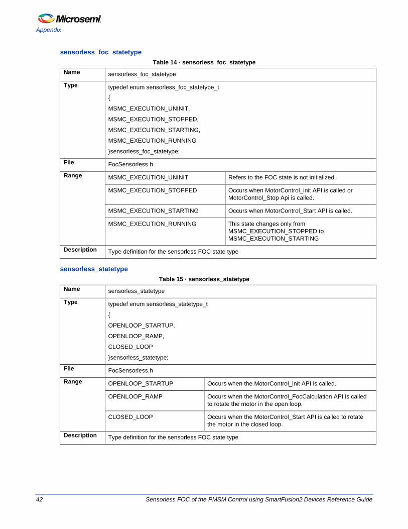
sensorless_foc_statetype Table 14 · sensorless_foc_statetype
Name sensorless_foc_statetype
Type typedef enum sensorless_foc_statetype_t
{
MSMC_EXECUTION_UNINIT,
MSMC_EXECUTION_STOPPED,
MSMC_EXECUTION_STARTING,
MSMC_EXECUTION_RUNNING
}sensorless_foc_statetype;
File FocSensorless.h
Range MSMC_EXECUTION_UNINIT Refers to the FOC state is not initialized.
MSMC_EXECUTION_STOPPED Occurs when MotorControl_init API is called or MotorControl_Stop Api is called.
MSMC_EXECUTION_STARTING Occurs when MotorControl_Start API is called.
MSMC_EXECUTION_RUNNING This state changes only from MSMC_EXECUTION_STOPPED to MSMC_EXECUTION_STARTING
Description Type definition for the sensorless FOC state type
sensorless_statetype Table 15 · sensorless_statetype
Name sensorless_statetype
Type typedef enum sensorless_statetype_t
{
OPENLOOP_STARTUP,
OPENLOOP_RAMP,
CLOSED_LOOP
}sensorless_statetype;
File FocSensorless.h
Range OPENLOOP_STARTUP Occurs when the MotorControl_init API is called.
OPENLOOP_RAMP Occurs when the MotorControl_FocCalculation API is called to rotate the motor in the open loop.
CLOSED_LOOP Occurs when the MotorControl_Start API is called to rotate the motor in the closed loop.
Description Type definition for the sensorless FOC state type
42 Sensorless FOC of the PMSM Control using SmartFusion2 Devices Reference Guide
FSM Implementation
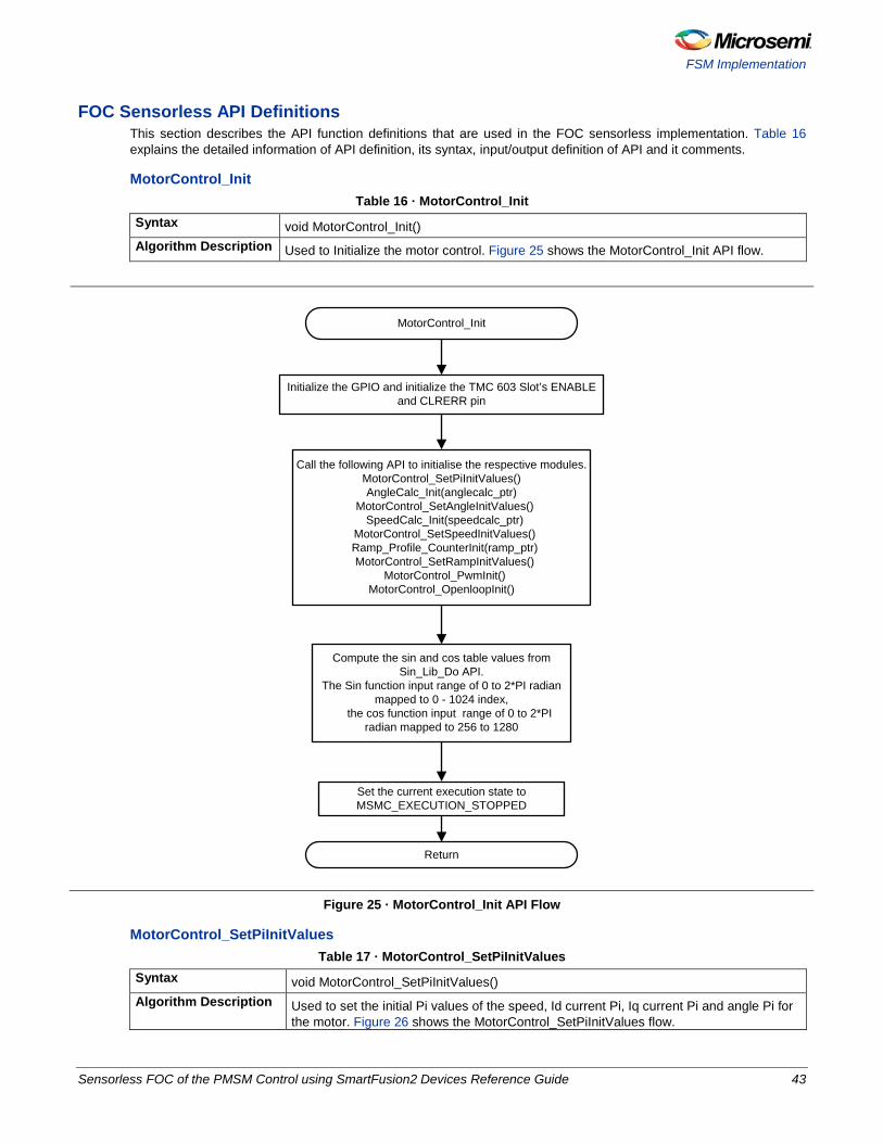
FOC Sensorless API Definitions This section describes the API function definitions that are used in the FOC sensorless implementation. Table 16 explains the detailed information of API definition, its syntax, input/output definition of API and it comments.
MotorControl_Init Table 16 · MotorControl_Init
Syntax void MotorControl_Init() Algorithm Description Used to Initialize the motor control. Figure 25 shows the MotorControl_Init API flow.
MotorControl_Init
Initialize the GPIO and initialize the TMC 603 Slot’s ENABLE and CLRERR pin
Call the following API to initialise the respective modules.MotorControl_SetPiInitValues()AngleCalc_Init(anglecalc_ptr)
MotorControl_SetAngleInitValues() SpeedCalc_Init(speedcalc_ptr)
MotorControl_SetSpeedInitValues() Ramp_Profile_CounterInit(ramp_ptr) MotorControl_SetRampInitValues()
MotorControl_PwmInit()MotorControl_OpenloopInit()
Compute the sin and cos table values from Sin_Lib_Do API.
The Sin function input range of 0 to 2*PI radian mapped to 0 - 1024 index,
the cos function input range of 0 to 2*PI radian mapped to 256 to 1280
Set the current execution state to MSMC_EXECUTION_STOPPED
Return
Figure 25 · MotorControl_Init API Flow
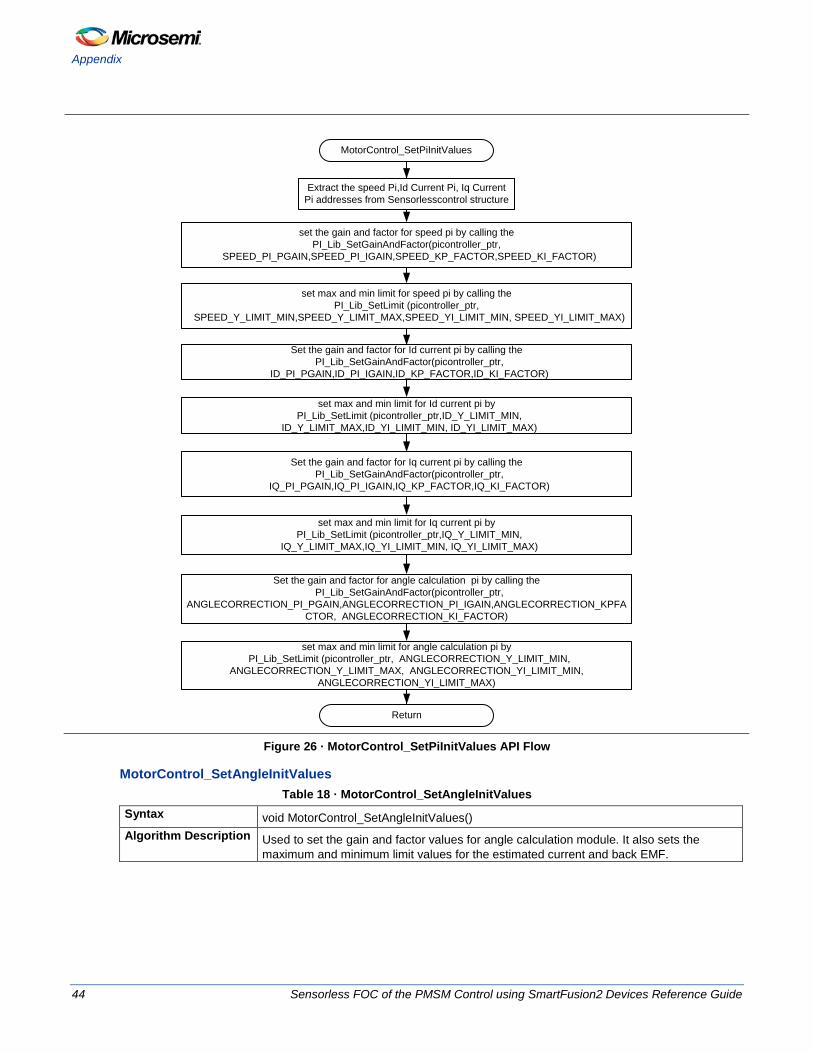
MotorControl_SetPiInitValues Table 17 · MotorControl_SetPiInitValues
Syntax void MotorControl_SetPiInitValues() Algorithm Description Used to set the initial Pi values of the speed, Id current Pi, Iq current Pi and angle Pi for
the motor. Figure 26 shows the MotorControl_SetPiInitValues flow.
Sensorless FOC of the PMSM Control using SmartFusion2 Devices Reference Guide 43
Appendix
MotorControl_SetPiInitValues
Return
set the gain and factor for speed pi by calling the PI_Lib_SetGainAndFactor(picontroller_ptr,
SPEED_PI_PGAIN,SPEED_PI_IGAIN,SPEED_KP_FACTOR,SPEED_KI_FACTOR)
Extract the speed Pi,Id Current Pi, Iq Current Pi addresses from Sensorlesscontrol structure
set max and min limit for speed pi by calling the PI_Lib_SetLimit (picontroller_ptr,
SPEED_Y_LIMIT_MIN,SPEED_Y_LIMIT_MAX,SPEED_YI_LIMIT_MIN, SPEED_YI_LIMIT_MAX)
Set the gain and factor for Id current pi by calling the PI_Lib_SetGainAndFactor(picontroller_ptr,
ID_PI_PGAIN,ID_PI_IGAIN,ID_KP_FACTOR,ID_KI_FACTOR)
set max and min limit for Id current pi by PI_Lib_SetLimit (picontroller_ptr,ID_Y_LIMIT_MIN,
ID_Y_LIMIT_MAX,ID_YI_LIMIT_MIN, ID_YI_LIMIT_MAX)
Set the gain and factor for Iq current pi by calling the PI_Lib_SetGainAndFactor(picontroller_ptr,
IQ_PI_PGAIN,IQ_PI_IGAIN,IQ_KP_FACTOR,IQ_KI_FACTOR)
set max and min limit for Iq current pi by PI_Lib_SetLimit (picontroller_ptr,IQ_Y_LIMIT_MIN,
IQ_Y_LIMIT_MAX,IQ_YI_LIMIT_MIN, IQ_YI_LIMIT_MAX)
Set the gain and factor for angle calculation pi by calling the PI_Lib_SetGainAndFactor(picontroller_ptr,
ANGLECORRECTION_PI_PGAIN,ANGLECORRECTION_PI_IGAIN,ANGLECORRECTION_KPFACTOR, ANGLECORRECTION_KI_FACTOR)
set max and min limit for angle calculation pi by PI_Lib_SetLimit (picontroller_ptr, ANGLECORRECTION_Y_LIMIT_MIN,
ANGLECORRECTION_Y_LIMIT_MAX, ANGLECORRECTION_YI_LIMIT_MIN, ANGLECORRECTION_YI_LIMIT_MAX)
Figure 26 · MotorControl_SetPiInitValues API Flow
MotorControl_SetAngleInitValues Table 18 · MotorControl_SetAngleInitValues
Syntax void MotorControl_SetAngleInitValues() Algorithm Description Used to set the gain and factor values for angle calculation module. It also sets the
maximum and minimum limit values for the estimated current and back EMF.
44 Sensorless FOC of the PMSM Control using SmartFusion2 Devices Reference Guide
FSM Implementation
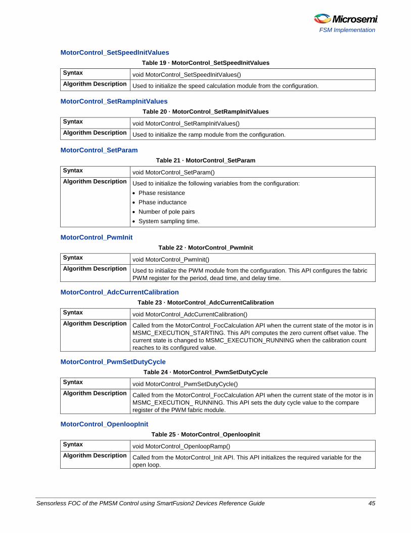
MotorControl_SetSpeedInitValues Table 19 · MotorControl_SetSpeedInitValues
Syntax void MotorControl_SetSpeedInitValues() Algorithm Description Used to initialize the speed calculation module from the configuration.
MotorControl_SetRampInitValues Table 20 · MotorControl_SetRampInitValues
Syntax void MotorControl_SetRampInitValues() Algorithm Description Used to initialize the ramp module from the configuration.
MotorControl_SetParam Table 21 · MotorControl_SetParam
Syntax void MotorControl_SetParam() Algorithm Description Used to initialize the following variables from the configuration:
• Phase resistance • Phase inductance • Number of pole pairs • System sampling time.
MotorControl_PwmInit Table 22 · MotorControl_PwmInit
Syntax void MotorControl_PwmInit() Algorithm Description Used to initialize the PWM module from the configuration. This API configures the fabric
PWM register for the period, dead time, and delay time.
MotorControl_AdcCurrentCalibration Table 23 · MotorControl_AdcCurrentCalibration
Syntax void MotorControl_AdcCurrentCalibration() Algorithm Description Called from the MotorControl_FocCalculation API when the current state of the motor is in
MSMC_EXECUTION_STARTING. This API computes the zero current offset value. The current state is changed to MSMC_EXECUTION_RUNNING when the calibration count reaches to its configured value.
MotorControl_PwmSetDutyCycle Table 24 · MotorControl_PwmSetDutyCycle
Syntax void MotorControl_PwmSetDutyCycle() Algorithm Description Called from the MotorControl_FocCalculation API when the current state of the motor is in
MSMC_EXECUTION_ RUNNING. This API sets the duty cycle value to the compare register of the PWM fabric module.
MotorControl_OpenloopInit Table 25 · MotorControl_OpenloopInit
Syntax void MotorControl_OpenloopRamp() Algorithm Description Called from the MotorControl_Init API. This API initializes the required variable for the
open loop.
Sensorless FOC of the PMSM Control using SmartFusion2 Devices Reference Guide 45
Appendix
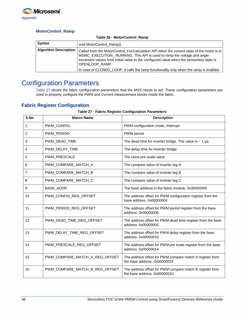
MotorControl_Ramp Table 26 · MotorControl_Ramp
Syntax void MotorControl_Ramp() Algorithm Description Called from the MotorControl_FocCalculation API when the current state of the motor is in
MSMC_EXECUTION_ RUNNING. This API is used to ramp the voltage and angle increment values from initial value to the configured value when the sensorless state is OPENLOOP_RAMP. In case of CLOSED_LOOP, it calls the ramp functionality only when the ramp is enabled.
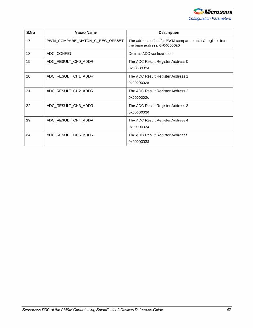
Configuration Parameters Table 27 shows the fabric configuration parameters that the MSS needs to set. These configuration parameters are used to properly configure the PWM and Current measurement blocks inside the fabric.
Fabric Register Configuration Table 27 · Fabric Register Configuration Parameters
S.No Macro Name Description
1 PWM_CONFIG PWM configuration mode, interrupt.
2 PWM_PERIOD PWM period
3 PWM_DEAD_TIME The dead time for inverter bridge. The value is ~ 1 µs.
4 PWM_DELAY_TIME The delay time for inverter bridge
5 PWM_PRESCALE The clock pre-scale value
6 PWM_COMPARE_MATCH_A The compare value of inverter leg A
7 PWM_COMPARE_MATCH_B The compare value of inverter leg B
8 PWM_COMPARE_MATCH_C The compare value of inverter leg C
9 BASE_ADDR The base address in the fabric module. 0x30000000
10 PWM_CONFIG_REG_OFFSET The address offset for PWM configuration register from the base address. 0x00000004
11 PWM_PERIOD_REG_OFFSET The address offset for PWM period register from the base address. 0x00000008
12 PWM_DEAD_TIME_REG_OFFSET The address offset for PWM dead time register from the base address. 0x0000000C
13 PWM_DELAY_TIME_REG_OFFSET The address offset for PWM delay register from the base address. 0x00000010
14 PWM_PRESCALE_REG_OFFSET The address offset for PWM pre scale register from the base address. 0x00000014
15 PWM_COMPARE_MATCH_A_REG_OFFSET The address offset for PWM compare match A register from the base address. 0x00000018
16 PWM_COMPARE_MATCH_B_REG_OFFSET The address offset for PWM compare match B register from the base address. 0x0000001C
46 Sensorless FOC of the PMSM Control using SmartFusion2 Devices Reference Guide
Configuration Parameters
S.No Macro Name Description
17 PWM_COMPARE_MATCH_C_REG_OFFSET The address offset for PWM compare match C register from the base address. 0x00000020
18 ADC_CONFIG Defines ADC configuration
19 ADC_RESULT_CH0_ADDR The ADC Result Register Address 0
0x00000024
20 ADC_RESULT_CH1_ADDR The ADC Result Register Address 1
0x00000028
21 ADC_RESULT_CH2_ADDR The ADC Result Register Address 2
0x0000002c
22 ADC_RESULT_CH3_ADDR The ADC Result Register Address 3
0x00000030
23 ADC_RESULT_CH4_ADDR The ADC Result Register Address 4
0x00000034
24 ADC_RESULT_CH5_ADDR The ADC Result Register Address 5
0x00000038
Sensorless FOC of the PMSM Control using SmartFusion2 Devices Reference Guide 47


Product Support
Microsemi SoC Products Group backs its products with various support services, including Customer Service, Customer Technical Support Center, a website, electronic mail, and worldwide sales offices. This appendix contains information about contacting Microsemi SoC Products Group and using these support services.
Customer Service Contact Customer Service for non-technical product support, such as product pricing, product upgrades, update information, order status, and authorization.
From North America, call 800.262.1060 From the rest of the world, call 650.318.4460 Fax, from anywhere in the world 408.643.6913
Customer Technical Support Center Microsemi SoC Products Group staffs its Customer Technical Support Center with highly skilled engineers who can help answer your hardware, software, and design questions about Microsemi SoC Products. The Customer Technical Support Center spends a great deal of time creating application notes, answers to common design cycle questions, documentation of known issues and various FAQs. So, before you contact us, please visit our online resources. It is very likely we have already answered your questions.
Technical Support Visit the Microsemi SoC Products Group Customer Support website for more information and support (http://www.microsemi.com/soc/support/search/default.aspx). Many answers available on the searchable web resource include diagrams, illustrations, and links to other resources on website.
Website You can browse a variety of technical and non-technical information on the Microsemi SoC Products Group home page, at http://www.microsemi.com/soc/.
Contacting the Customer Technical Support Center Highly skilled engineers staff the Technical Support Center. The Technical Support Center can be contacted by email or through the Microsemi SoC Products Group website.
Email You can communicate your technical questions to our email address and receive answers back by email, fax, or phone. Also, if you have design problems, you can email your design files to receive assistance. We constantly monitor the email account throughout the day. When sending your request to us, please be sure to include your full name, company name, and your contact information for efficient processing of your request. The technical support email address is [email protected].
My Cases Microsemi SoC Products Group customers may submit and track technical cases online by going to My Cases.
Sensorless FOC of the PMSM Control using SmartFusion2 Devices Reference Guide 49

Product Support
Outside the U.S. Customers needing assistance outside the US time zones can either contact technical support via email ([email protected]) or contact a local sales office. Sales office listings can be found at www.microsemi.com/soc/company/contact/default.aspx.
ITAR Technical Support For technical support on RH and RT FPGAs that are regulated by International Traffic in Arms Regulations (ITAR), contact us via [email protected]. Alternatively, within My Cases, select Yes in the ITAR drop-down list. For a complete list of ITAR-regulated Microsemi FPGAs, visit the ITAR web page.
50 Sensorless FOC of the PMSM Control using SmartFusion2 Devices Reference Guide


50200536-1/02.14
Microsemi Corporate Headquarters One Enterprise, Aliso Viejo CA 92656 USA Within the USA: +1 (949) 380-6100 Sales: +1 (949) 380-6136 Fax: +1 (949) 215-4996
Microsemi Corporation (NASDAQ: MSCC) offers a comprehensive portfolio of semiconductor solutions for: aerospace, defense and security; enterprise and communications; and industrial and alternative energy markets. Products include high-performance, high-reliability analog and RF devices, mixed signal and RF integrated circuits, customizable SoCs, FPGAs, and complete subsystems. Microsemi is headquartered in Aliso Viejo, Calif. Learn more at www.microsemi.com.
© 2014 Microsemi Corporation. All rights reserved. Microsemi and the Microsemi logo are trademarks of Microsemi Corporation. All other trademarks and service marks are the property of their respective owners.