Embed Size (px)
Citation preview

MAINTENANCEMANUAL
PN: 15-9314


WARNING: To prevent fire or shock hazard, do not expose the printer torain or moisture.

DisclaimerInformation in this publication is subject to change without notice. However, as productimprovements become available, Ithaca Peripherals will make every effort to provide updatedinformation for the products described in this publication.
Ithaca Peripherals cannot, however, guarantee that changes in software and equipment made byother manufacturers, and referred to in here, do not affect the applicability of the information in thispublication.
Copyright© 1998-1999 Ithaca Peripherals. All rights reserved.Revision C, December 1999Printed in USA
No part of this publication may be reproduced, stored in a retrieval system, or transmitted, in anyform or by any means, mechanical, photocopying, recording, or otherwise, without the prior writtenpermission of Ithaca Peripherals.
TrademarksIthaca and PcOS are registered trademarks of Ithaca Peripherals. Ithaca Peripherals is a TransactTechnologies Incorporated Company. Epson and ESC/POS are registered trademarks of SeikoEpson Corporation. Axiohm is a registered trademark of Dardell Technologies. IBM is a registeredtrademark of the International Business Machines Corporation.

Federal Communications Commission RadioFrequency Interference StatementThe Series 150 Printer complies with the limits for a Class A computing device in accordance withthe specifications in Part 15 of FCC rules, which are designed to minimize radio frequencyinterference during installation; however, there is no guarantee that radio or television interferencewill not occur during a particular installation. If this equipment does cause interference to radio ortelevision reception, which can be determined by turning the equipment off and on while the radio ortelevision is on, the user is encouraged to try to correct the interference by one or more of thefollowing measures:
♦ Reorient the radio or television receiving antenna;
♦ Relocate the printer with respect to the receiver;
♦ Plug the printer and receiver into different circuits.
If necessary, the user may consult their dealer or an experienced radio/television technician foradditional suggestions. The user may find the following booklet prepared by the FederalCommunications Commission helpful: How to Identify and Resolve Radio/TV InterferenceProblems.
The booklet is available from the United States Government Printing Office, Washington, DC20402. Ask for stock number 004-000-00345-4.
Canadian Department of Communications RadioInterference StatementThe Series 150 Printer does not exceed Class A limits for radio noise emissions from digitalapparatus set out in the Radio Interference Regulations of the Canadian Department ofCommunications.
UL, C-UL, VDE, CE StatementIthaca Peripherals’ printers are UL and C-UL Listed, VDE Certified, and carry the CE Mark.


Table of Contents i
TABLE OF CONTENTS
PRODUCT INFORMATION 1What is in this book? ...............................................................................................................1
Who should read this book?...............................................................................................1
What does it cover? ...........................................................................................................1
Where can you find more information?...............................................................................1
Contacting Ithaca Peripherals ..................................................................................................1
Warranty Information..............................................................................................................2
Options .............................................................................................................................2
Service..............................................................................................................................2
Ordering Supplies....................................................................................................................2
Paper ................................................................................................................................3
Ribbon Cassettes...............................................................................................................3
Take-up Spool...................................................................................................................3
Print Head and Clamp .......................................................................................................3
Cables...............................................................................................................................4
Description of the Series 150 Printer ........................................................................................4
Series 150 Models .............................................................................................................5
Standard Features..............................................................................................................6
Optional Features ..............................................................................................................6
Technical Specifications ..........................................................................................................7
Printing.............................................................................................................................7
Print Characteristics ..........................................................................................................7
Reliability .........................................................................................................................8
Dimensions .......................................................................................................................8
Weight ..............................................................................................................................8
Power Requirements..........................................................................................................8
Environmental Conditions..................................................................................................8
Communication Interfaces and Cash Drawer Connectors..........................................................9
Serial Cable ......................................................................................................................9
Parallel Cable..................................................................................................................11
IEEE 1284 Bidirectional Parallel Cable ...........................................................................11

Series 150 Maintenance Manualii
Cash Drawer Pin Assignments.........................................................................................11
CLEANING AND ADJUSTMENTS 13Cleaning the Printer ...............................................................................................................13
Making Adjustments..............................................................................................................13
Diagnosing the Print Quality............................................................................................14
Tools Required to Adjust the Platen Gap..........................................................................14
Adjusting the Platen Gap .................................................................................................15
ASSEMBLY/DISASSEMBLY 17Precautions for Disassembly ..................................................................................................17
Assembly/Disassembly Tools ..........................................................................................17
Power Cord ...........................................................................................................................18
Communication Cables ..........................................................................................................19
Serial Cable ....................................................................................................................19
Parallel Cable..................................................................................................................20
Cash Drawer Cables ..............................................................................................................20
Ribbon Cassette.....................................................................................................................21
Removing the Ribbon Cassette.........................................................................................21
Installing the Ribbon Cassette..........................................................................................21
Print Head .............................................................................................................................23
Removing the Print Head.................................................................................................23
Installing the Print Head ..................................................................................................25
Covers...................................................................................................................................26
Cassette Cover without Knife.................................................................................................27
Cassette Cover with Knife......................................................................................................27
Paper Cover with Journal Lock ..............................................................................................28
Electronics and Mechanism Base ...........................................................................................29
Knife Option (Model 151)......................................................................................................31
Knife Assembly .....................................................................................................................32
Take-up Motor Assembly Kit (Models 152 and 153) ..............................................................34
Switch Assembly and Light Pipes ..........................................................................................36
Print Mechanism....................................................................................................................37
Validation Mechanism ...........................................................................................................38
Carriage Assembly ................................................................................................................39
Carriage Motor Assembly......................................................................................................40
Forms Compensation .............................................................................................................41
Original Forms Compensation Assembly (Models 151 and 152) .............................................42

Table of Contents iii
Original Forms Compensation Assembly (Model 153)............................................................43
Reduced-sound Forms Compensation Assembly .....................................................................44
Original Line Feed Motor and Gears ......................................................................................45
Reduced-sound Line Feed Motor and Gear.............................................................................46
Cash Drawer Harnesses.........................................................................................................47
Parallel/Serial Communication PC Boards .............................................................................48
Controller PC Board..............................................................................................................49
Power Supply........................................................................................................................50
AC Inlet and AC Switch ........................................................................................................51
TROUBLESHOOTING 53Determining the Problem .......................................................................................................54
Operating the Keypad ............................................................................................................67
Buttons ...........................................................................................................................67
AC Power Switch............................................................................................................68
Indicator Lights .....................................................................................................................68
Printer Fault Indicators ..........................................................................................................69
Product Self-Tests .................................................................................................................70
Level 0 Diagnostics .........................................................................................................70
Extended Diagnostics ......................................................................................................70
Checking Connections and Resistance ....................................................................................73
Print Head.......................................................................................................................73
Space Motor Assembly....................................................................................................74
Line Feed Motor..............................................................................................................74
APPENDIX A: THEORY OF OPERATION 75Electrical Operation...............................................................................................................76
Circuit Operation ............................................................................................................76
Microprocessor and Peripheral Circuits..................................................................................77
Microprocessor (U1: 80C154) .........................................................................................77
Program ROM (U4) ........................................................................................................77
Program RAM (U2) ........................................................................................................77
RAM (U5) ......................................................................................................................77
LSI (M7U042-026) .........................................................................................................77
Initialization ..........................................................................................................................78
Interface Control ...................................................................................................................78
Parallel Interface .............................................................................................................78
Serial Interface................................................................................................................78

Series 150 Maintenance Manualiv
Print Head Drive Circuit ........................................................................................................79
Carriage Drive.......................................................................................................................79
Space Motor Control .......................................................................................................79
Slit Encoder ....................................................................................................................80
Line Feed ..............................................................................................................................81
Alarm Circuits.......................................................................................................................81
Drive Circuit Fault Alarm Circuit ....................................................................................81
Head Overheat Alarm Circuit ..........................................................................................81
Power Supply ........................................................................................................................82
AC Input ...............................................................................................................................82
Mechanical Operation............................................................................................................82
Print Head Mechanism and Operation..............................................................................82
Print Head Operation.......................................................................................................83
Space Mechanism and Operation ...........................................................................................83
Ribbon Feed Mechanism and Operation .................................................................................84
Ribbon Feed Operation....................................................................................................84
Ribbon Cartridge.............................................................................................................84
Receipt Feed Motor ...............................................................................................................84
Paper Exhaust .......................................................................................................................84
APPENDIX B: PARTS LISTS 85Packing Materials/Publications ..............................................................................................86
Printer Assembly ...................................................................................................................88
Paper Cover ..........................................................................................................................90
Cassette Cover without Knife.................................................................................................91
Cassette Cover with Knife......................................................................................................92
Electronic Base......................................................................................................................93
Cutter....................................................................................................................................94
Knife Assembly .....................................................................................................................95
Take-up Motor Assembly ......................................................................................................97
Switch Assembly and Light Pipes ..........................................................................................98
Print and Validation Mechanism Assemblies ..........................................................................99
Carriage Assembly ..............................................................................................................101
Carriage Motor Assembly....................................................................................................102
Mechanism Base (Original Forms Compensation Assembly).................................................103
Mechanism Base (Reduced-sound Forms Compensation Assembly)......................................105
Original Forms Compensation Assembly (Models 151 and 152) ...........................................107
Original Forms Compensation Assembly (Model 153)..........................................................108

Table of Contents v
Reduced-sound Forms Compensation Assembly ...................................................................109
Original Line Feed Motor and Gears ....................................................................................110
Reduced-sound Line Feed Motor and Gear...........................................................................111
Electronic Base Assembly....................................................................................................112
APPENDIX C: SCHEMATICS 115Controller/ASIC ..................................................................................................................116
Memory/Receipt Motor Drive..............................................................................................117
Space Motor Control ...........................................................................................................118
Head Control.......................................................................................................................119
Control Interface .................................................................................................................120
Control Interface .................................................................................................................121
Interface..............................................................................................................................122
USB Interface......................................................................................................................123


Product Information 1
PRODUCT INFORMATION
WHAT IS IN THIS BOOK?Who should read this book?This book is intended for trained, service technicians.
What does it cover?This book only covers the Series 150 Printer, not the entire point-of-sale system, but it willtell you all you need to know about properly maintaining and servicing the printer. You willlearn how to clean and adjust the printer, troubleshoot problems, and disassemble theprinter.
This book also provides general and technical information about the printer, so you willlearn what the features are, how reliable it is, and what its printing capabilities are.
Where can you find more information?A Programmer’s Guide is available to help you program a point-of-sale terminal or apersonal computer to work with the printer. It describes the commands the printerrecognizes to perform its functions.
An Operator’s Guide is also available and is intended for new or experienced operators. Itcovers setting up and using the Series 150 Printer with any point-of-sale system.
For information about ordering these books, refer to the next section.
CONTACTING ITHACA PERIPHERALSThe Sales and Technical Support Departments will be able to help you with most of yourquestions. Contact the Technical Support Department to receive technical support, orderdocumentation, receive additional information about the Series 150 Printer, obtain informationabout your warranty, or send a printer in for service. To order supplies or receive informationabout other Ithaca Peripherals products, contact the Sales Department.
You may reach both the Sales and Technical Support Departments at the following address andtelephone or fax numbers:

Series 150 Maintenance Manual2
Ithaca Peripherals20 Bomax DriveIthaca, NY 14850 USA
Main telephone (607) 257-8901Main fax (607) 257-8922Sales fax (607) 257-3868Technical Support fax (607) 257-3911Technical Support E-mail [email protected] site http://www.ithper.com
WARRANTY INFORMATIONOptionsAll Ithaca Peripherals PcOS Series 150 Printers come with a standard 24-month warrantycovering both parts and labor that starts upon shipment from the factory. An optionalwarranty, covering both parts and labor for an additional 12 months, may be purchasedseparately.
For more information concerning the warranty options, please contact the Sales Departmentat Ithaca Peripherals. See “Contacting Ithaca Peripherals” on page 1.
ServiceIthaca Peripherals has a full service organization to meet your printer service and repairrequirements. If your printer needs service, please directly contact Ithaca Peripherals’Technical Support Department at (607) 257-8901 for a return authorization.
Ithaca Peripherals offers the following service programs to meet your needs:
♦ Extended Warranty,
♦ Depot Repair,
♦ Maintenance Contract, and
♦ Internet Support.
ORDERING SUPPLIESYou may order supplies by calling Ithaca Peripherals or by faxing the order form shipped in thebox with the printer.
♦ Phone (607) 257-8901, and ask for the Sales department, or
♦ Fax the order form to (607) 257-3868.

Product Information 3
You may order the following supplies:
♦ Paper,
♦ Ribbon cassettes,
♦ Take-up spools,
♦ Print heads, and
♦ Cables.
PaperPaper Type Dimensions Stock Number
Receipt Paper Single-ply Width: 3.25 inches (82.55 mm)Diameter: 3.5 inches (88.9 mm)Length: 240 feet (7315 cm)
100-1667
Receipt-Journal Paper Double-ply Width: 3.25 inches (82.55 mm)Diameter: 3.5 inches (88.9 mm)Length: 125 feet (3810 cm)
98-0558
Receipt-Journal Paper Triple-ply Width: 3.25 inches (82.55 mm)Diameter: 3.5 inches (88.9 mm)Length: 85 feet (2591 cm)
06-0720
Ribbon CassettesColor Supplier Stock Number
Black Ithaca Peripherals 100-7565
Purple Ithaca Peripherals 100-7859
Note: Your warranty may be voided if other than genuine Ithaca Peripheralsribbons are used.
Take-up SpoolTake-up Spool Stock Number
Journal Take-up Spool 90-02026
Print Head and ClampPrint Head and Clamp Stock Number
Print Head R90-7337
Print Head Clamp R06-0571

Series 150 Maintenance Manual4
CablesCables Stock Number
110V Power Cable 06-0561
230V Power Cable 06-0806
Parallel Communication Cable 253-9800007
Serial Communication Cable PC, 9-pin Female to 9-pin Female PC, 9-pin Female to 25-pin Female
10-202010-2021
DESCRIPTION OF THE SERIES 150 PRINTER
The PcOS (personal computer, point-of-sale) Series 150 Printer is a stand-alone, 40-column,high-speed impact printer. The Series 150 Printer performs a variety of functions in a point-of-sale environment and is available in the following models:
♦ Model 151: Receipt Printer;
♦ Model 152: Receipt/Journal Printer; and
♦ Model 153: Receipt/Validation Printer (with or without Journal).

Product Information 5
Series 150 Models
PcOS Model 151 Receipt PrinterThe Model 151 is a receipt printer used for applications requiring high-speed printing ofreceipts.
♦ 340 characters per second bidirectional print
♦ 41-column print at 17 characters per inch
PcOS Model 152 Receipt and Journal PrinterThe Model 152 is a receipt and journal printer used for applications requiring atransaction audit trail (journal) in addition to high-speed printing of receipts.
♦ 340 characters per second bidirectional print
♦ 41-column print at 17 characters per inch
♦ Journal take-up
PcOS Model 153 Receipt, Journal, and Validation PrinterThe Model 153 is a receipt and validation printer (with or without journal) used forapplications requiring up to 15 lines of print on inserted forms such as checks or chargeslips. In addition, it provides the same high-speed journal and receipt printing as theModel 152.
♦ 340 characters per second bidirectional print
♦ 41-column print at 17 characters per inch
♦ Journal take-up (optional)
♦ Form insertion sensor
♦ 15-line validation

Series 150 Maintenance Manual6
Standard FeaturesThe following features and items are standard on all Series 150 Printers:
♦ Centronics parallel interface with 6K buffer;
♦ Internal International Power Supply (95 to 265 VAC);
♦ Operating controls and lights
Power On/Off switch and indicator,
FEED button,
RELEASE button, and
RESUME button;
♦ Ready, Alarm, and Power LED’s;
♦ Paper out sensor;
♦ Operator controlled self-test;
♦ Cash drawer connectors (RJ12) and driver (24V, 1.5 amp pulse for approximately 150ms; drawer open/closed status reporting);
♦ Nine-pin stored energy print head;
♦ Short line-seeking logic;
♦ Characters and graphics
Lowercase characters with descenders,
340 characters per second bidirectional print,
41-column print at 17 characters per inch,
Emphasized and enhanced print, and
IBM compatible all-points-addressable (APA) graphics;
♦ Software-controlled vertical spacing;
♦ Snap-on ribbon cassette; and
♦ Steel receipt tear-off bar.
Optional FeaturesThe optional features either replace a standard feature or enhance the operation of theprinter. All optional features are installed at the factory and must be selected when theprinter is ordered.
♦ RS-232C serial communication interface
♦ IEEE 1284 bidirectional parallel communication interface
♦ USB (Universal Serial Bus)
♦ OPOS drivers
♦ Knife (Model 151)
♦ Journal cover lock
♦ Custom colors and logo

Product Information 7
TECHNICAL SPECIFICATIONSPrinting♦ Printing method Impact dot matrix
♦ Head wire arrangement 9-pins in line
♦ Print wire diameter 0.012 inch (0.34 mm)
♦ Print wire pitch 0.013 inch (0.35 mm)
♦ Print directions bidirectional, logic-seeking
♦ Print zone 2.8 inches (71.1 mm) or 2.4 inches (61.0 mm)
Print CharacteristicsThe Series 150 Printer prints characters in a variety of pitches as shown in the followingtable. Each pitch can also be printed in a variety of styles affecting the appearance of thecharacters and the speed of the printer.
For information about programming the printer to print a particular pitch or style, pleaserefer to the Programmer’s Guide. You may order the Programmer’s Guide from IthacaPeripherals. See “Contacting Ithaca Peripherals” on page 1.
Pitch (Characters per Inch) Maximum Charactersper Line
Characters per Second
8 18 220
10 24 275
12 28 330
15 36 340
17.1 (Condensed) 41 340
20 (Super condensed) 48 340
24 (Super condensed) 57 340
5 (Double-wide) 12 175
6 (Double-wide) 14 175
7.5 (Double-wide) 18 175
8.5 (Condensed, double-wide) 20 175
10 (Condensed, double-wide) 24 175
12 (Super condensed, double-wide) 28 175

Series 150 Maintenance Manual8
Reliability♦ Mean time between failure (except print head): 30,000 hours (Model 151)
♦ Print head life: 200 million characters
♦ Mean time to repair: 15 minutes
Dimensions♦ Width: 6.63 inches (168 mm)
♦ Length: 11.25 inches (286 mm)
♦ Height: 5.75 inches (146 mm)
Weight♦ Approximate weight: 7.0 pounds (3.2 kg)
♦ Approximate shipping weight: 10.0 pounds (4.5 kg)
Power RequirementsThe Series 150 Printer is designed to be AC self-powered in domestic and internationalmarkets. The printer is equipped with a universal input power supply that is designed tooperate worldwide without modification.
SupplyVoltageRating(VAC)
SupplyVoltage
Range (VAC)
Frequency(Hz)
RatedPower(watts)
Current Idle(amps)
CurrentPrinting(amps)
100 - 240 90 - 264 47 - 63 45 0.08 @ 120VAC0.04 @ 240VAC
0.9 @ 120VAC0.5 @ 240VAC
Environmental ConditionsThe printer will run at its best when stored and operated in an environment that meets thefollowing temperature and humidity conditions:
♦ Operating temperature: 32° to 122°F (0° to 50°C)
♦ Storage temperature: -14° to +140°F (-10° to +60°C)
♦ Operating relative humidity: 10% to 90% (noncondensing)
♦ Storage relative humidity: 5% to 90%

Product Information 9
COMMUNICATION INTERFACES AND CASHDRAWER CONNECTORS
Serial CableCable RequirementsThe PcOS Series 150 Printer requires an RS-232C shielded cable, no more than 50 feetlong. The cable must be UL and CSA approved.
RS-232C CommunicationThe RS-232C interface uses the following protocol and communication characteristics:
♦ Up to 19.2K baud
♦ Up to 6K buffer
♦ Ready/Busy or XON/XOFF protocol
♦ Communications diagnostic mode
Pin Assignments for 9-pin Printer ConnectorPin Name Description
1 DCD Data Carrier Detect
2 RX Receive Data
3 TX Transmit Data
4 DTR Data Terminal Ready
5 GND Signal Ground
6 DSR Data Set Ready
7 RTS Request To Send
8 CTS Clear To Send
9 SSD Secondary Data

Series 150 Maintenance Manual10
Serial Cable ConfigurationsThe following cable configurations are for different host requirements.
Serial Personal Computer to Series 150 (Null Modem)
Ithaca Peripherals’ part number, 10-2020, 9-pin to 9-pin female cable for PcOSSeries 150 Printers should be used to connect personal computers with 9-pin serialports.
DTRDSRDCDTXDRXDGNDRTSCTS
46132578
DTRDSRDCDTXDRXDGNDRTSCTS
46132578
Nine-pinFemale
PC
Nine-pinFemalePrinter
PN 10-2020
Serial AT to Series 150 (Null Modem)
Ithaca Peripherals’ part number, 10-2021, 9-pin to 25-pin female cable for PcOSSeries 150 printers should be used to connect personal computers with 25-pin serialports.
DTRDSRDCDTXDRXDGNDRTSCTS
206823745
DTRDSRDCDTXDRXDGNDRTSCTS
46132578
Twenty- f ive-pinFemale
PC
Nine-pinFemalePrinter
PN 10-2021

Product Information 11
Parallel CableCable RequirementsThe PcOS Series 150 Printer requires a 25-pin male D-shell connector at the printer. Toconnect the printer to most personal computers, use Ithaca Peripherals’ part number:253-9800007 25-pin male to 25-pin male parallel interconnect cable.
Pin AssignmentsPin(s) Signal Description Direction
1 STROBE Clock data to printer Host to Printer
2-9 D0 - D7 Data Host to Printer
10 ACK\ Printer accepted data Printer to Host
11 BUSY Printer busy Printer to Host
12 PE Paper Out/Status Printer to Host
13 SLCT Printer selected Printer to Host
14 AUTOFD Autofeed paper Host to Printer
15 ERR\ Printer error Printer to Host
16 INIT\ Initialize the printer Host to Printer
17 SLIN Select printer Host to Printer
18-25 GND Ground
IEEE 1284 Bidirectional Parallel CableThe PcOS Series 150 Printer supports the IEEE 1284, bidirectional, parallel-peripheral,interface standard, Modes 0 and 4. This provides a bidirectional link to the parallel port.Refer to the Programmer’s Guide for further information. See “Contacting IthacaPeripherals” on page 1.
Cash Drawer Pin AssignmentsIthacaFunction Drawer 1 Drawer 2
Drawer Drive + Pin 4 Pin 4
Drawer Drive - Pin 5 Pin 1
Status Signal Pin 2 Pin 2
Status Ground Pin 3 Pin 3
Frame Ground Pin 6 Pin 6
No Connect Pin 1 Pin 5

Series 150 Maintenance Manual12
Epson/AxiohmFunction Drawer 1 Drawer 2
Drawer Drive + Pin 4 Pin 4
Drawer Drive - Pin 2 Pin 5
Status Signal Pin 3 Pin 3
Status Ground Pin 6 Pin 6
Frame Ground Pin 1 Pin 1
No Connect Pin 5 Pin 2
StarFunction Drawer 1 Drawer 2
Drawer Drive + Pin 2 Pin 2
Drawer Drive - Pin 3 Pin 3
Status Signal Pin 6 Pin 6
Frame Ground Pin 1 Pin 1
No Connect Pin 4 Pin 4
No Connect Pin 5 Pin 5

Cleaning and Adjustments 13
CLEANING ANDADJUSTMENTS
CLEANING THE PRINTERRemove paper dust periodically by using a vacuum cleaner or air compressor.
Caution: Do not use alcohol- or petroleum-based chemicals to clean the printeras these will damage the plastic parts. The carriage rack isparticularly sensitive and will be permanently damaged if exposed tothese chemicals. Take special care not to get the cleaner on anyelectronic components.
None of the internal parts of the printer require lubrication or routine maintenance. Apply acommon cleaner such as fantastik® or Formula 409® to a damp cloth and gently wipe thesurface of the printer and keypad.
MAKING ADJUSTMENTSThe adjustments described in this section are required to correct print head drag, print qualityflaws, or the print mechanism.
If the print density on a print sample is consistent from top to bottom and the print head does notdrag, no adjustment is necessary. If the print head drags or if the print sample is inconsistent,adjust the platen gap. (See page 15).

Series 150 Maintenance Manual14
Diagnosing the Print QualityFollow the flow chart to determine which procedure to use to correct specific printproblems.
N
N
YAdjust platen gap
?
Prints oneither top or bottom, but
not both?
en gap.
End
N
Y
Y
Replace ribbon.Prints
toolight?
Stilllight
Adjust plat
Print Quality DiagnosisExamine the print sample.
Tools Required to Adjust the Platen GapCaution: Using the wrong tools may cause personal injury or damage the
printer. Be sure to use the proper tools when maintaining orservicing the Series 150 Printer.
The following list provides the tools necessary to adjust the platen gap:
♦ #1 Phillips screwdriver,
♦ 0.012-inch (0.305-mm) thickness gauge,
♦ Paper clip, and
♦ Nut driver.

Cleaning and Adjustments 15
Adjusting the Platen Gap
2
3
4
5
6
7

Series 150 Maintenance Manual16
1. Turn off the printer.
2. Remove the paper from the printer.
3. Remove the ribbon cassette (1).
4. Move the print head (3) to the right.
5. With a 0.012-inch (0.305 mm) thickness gauge, check the air gap between the platen (2)and the print head (3). The air gap should measure 0.012 ± 0.002 inch (0.305 ± 0.050mm).
6. If an adjustment is needed, press down on the outer ring of the adjusting gear (4) withthe straightened end of a paper clip, and turn the adjusting screw (5) with a #1 Phillipsscrewdriver until the gap measures 0.012 ± 0.002 inch (0.305 ± 0.050 mm).
Turn the adjusting gear (4) counterclockwise to decrease the air gap, clockwise toincrease the air gap.
7. Move the print head (3) to the left end of the platen (2), and check the air gap as in Step5.
8. If an adjustment is needed, loosen the nut (6) at the left end of the carriage support rail(7).
Move the rail up or down to decrease the air gap.
9. Retighten the nut (6).
10. Recheck the air gap at both sides of the platen (2).

Assembly/Disassembly 17
ASSEMBLY/DISASSEMBLYPRECAUTIONS FOR DISASSEMBLY
Before disassembling any part of the printer, be sure to turn off the power. Disconnect the ACpower cord, communication cable, and cash drawer cables.
Caution: Controller board and keypad PC board can easily be damaged bystatic electricity. Observe electrostatic discharge (ESD) precautions.Wear a grounded wrist strap, and use a static mat or other protectedwork surface. Do not place the printed circuit boards directly on theprinter or floor.
Assembly/Disassembly Tools
Caution: Using the wrong tools may cause personal injury or damage theprinter. Be sure to use the proper tools when maintaining orservicing the printer.
The following list provides the necessary tools for properly maintaining the Series 150Printer.
♦ Screwdrivers
#0 Phillips
#1 Phillips
#2 Phillips
Small flat blade
Large flat blade
♦ Nut Drivers
0.16 inch (5/32 inch) (4.1 mm)
0.19 inch (5/16 inch) (4.8 mm)
0.22 inch (5.5 mm)
♦ Miscellaneous
0.012-inch (0.305-mm) thickness gauge
Hobby knife
Small needle-nose pliers

Series 150 Maintenance Manual18
POWER CORDCaution: The printer must be grounded through the three-prong power
connector. Do not use a ground defeating adapter.
PowerSwitch
On Off
Back ofPrinter
1. Be sure to turn off the power switch.
Back ofPrinter
PowerCord
2. Disconnect the external AC power source and the power cord from the power socket locatedon the back of the printer.

Assembly/Disassembly 19
COMMUNICATION CABLESDepending on the interface your system uses, disconnect either the serial or parallelcommunication cable from the connector on the back of the printer.
Serial Cable
Back ofPrinter
9-pin SerialInterface Connector
1. Turn off the printer and host system or personal computer.
2. Loosen the two mounting screws on each side of the cable connector.
3. Disconnect the 9-pin serial interface cable from the connector located on the back of theprinter.
Refer to the “Communication Interfaces and Cash Drawer Connectors” on page 9 forinformation on the serial cable requirements.

Series 150 Maintenance Manual20
Parallel Cable
Back ofPrinter
25-pin ParallelInterface Connector
1. Turn off the printer and host system or personal computer.
2. Disconnect the 25-pin parallel interface cable from the connector located on the back ofthe printer.
Refer to the “Communication Interfaces and Cash Drawer Connectors” on page 9 forinformation on the parallel cable requirements.
CASH DRAWER CABLES
Back ofPrinter
Connector 1Cash DrawerConnector 2
Cash Drawer
1. Turn off the printer.
2. Disconnect the cash drawer cable to the connectors located on the back of the printer.
If you need an adapter, contact the Technical Support Department at Ithaca Peripherals. See“Contacting Ithaca Peripherals” on page 1.

Assembly/Disassembly 21
RIBBON CASSETTERemoving the Ribbon Cassette1. Open the cassette cover.
2. Grasp both sides of the cassette. Lift and rock the cassette towards you. Do not pull thecassette straight up.
Installing the Ribbon Cassette
3. Holding the ribbon cassette with the Mylar guide facing away from you, insert the frontof the cassette into the carriage.
Note: It is important to fit the front edge of the ribbon cassette into the carriage first.Do not place the ribbon cassette flat on the carriage.
Series 150 Maintenance Manual22
RibbonCassette
Clamp
Carriage
TabPrint head
2. Rock the ribbon cassette forward, toward the print head, and then press down on it untilthe tabs on the cassette snap into the clamps on the carriage.
3. Tighten the ribbon by turning the knob on the cassette clockwise.
4. Close the cassette cover.
5. Turn on the printer (if already installed).

Assembly/Disassembly 23
PRINT HEADReplace the print head when the characters are consistently misprinting.
Removing the Print Head
Caution: The print head gets very hot.
PowerSwitch
On Off
Back ofPrinter
1. Turn off the printer, and allow the print head to cool for at least three minutes beforereplacing it.
CassetteCover
2. Open the cassette cover.
3. Remove the ribbon cassette. (See page 21).

Series 150 Maintenance Manual24
Note: In the following illustrations, the heat sink is not shown for clarity.
4. Open the print head clip by grasping the tab on the right side of the clip and rotating itfrom right to left.
5. Lift the print head straight up out of the carriage.

Assembly/Disassembly 25
Installing the Print Head
Note: In the following illustration, the heat sink is not shown for clarity.
6. Slide the black wire guide on the back of the print head into the slot on the carriage.Make sure the tabs on the wire guide hold the print head against the carriage.
2. Align the PC board on the bottom of the print head with the receptacle on the carriage.
3. Press the print head into the carriage. Do not force the PC board into the receptacle.Make sure it is lined up properly.
4. Close the print head clip by rotating it from left to right and latching it into place.
5. Replace the ribbon cassette. (See page 21).
6. Close the cassette cover.

Series 150 Maintenance Manual26
COVERS
1 2
5
4
3
1. Unlock the optional journal lock (1) located on the paper cover (2).
2. Open the paper cover (2) until it unsnaps from the base cabinet (3).
3. Remove the take-up spindle (4).
4. Open the cassette cover (5) until it unsnaps from the base cabinet (3).

Assembly/Disassembly 27
CASSETTE COVER WITHOUT KNIFE
3
3
1
2
1. Remove the paper covers. (See page 26).
2. Unscrew the two screws (3) holding the tear bar (2) to the cassette cover (1).
3. Remove the tear bar (2).
CASSETTE COVER WITH KNIFE
1. Remove the paper covers. (See page 26).

Series 150 Maintenance Manual28
PAPER COVER WITH JOURNAL LOCK
3
5
4
2
1
7
6
1. Remove the paper covers. (See page 26).
2. Unscrew the screw (1) and remove the journal lock extension (2) from the lock set (3).
3. Unscrew the lock set hex nut (4) and remove the lock barrel (3) from the paper cover (5).
Installation notes:
1. Position the key opening in the tumbler assembly (6) before inserting the key (7) as shown inthe illustration.
2. Insert the key into the tumbler assembly (6) before inserting the tumbler assembly into thelock barrel (3). Position the key teeth as shown in the illustration.
3. Install lock barrel (3) in the paper cover (5) with in notch towards the outside.

Assembly/Disassembly 29
ELECTRONICS AND MECHANISM BASE1
2
3
6
5
4
7
8
3

Series 150 Maintenance Manual30
1. Remove the paper covers. (See page 26).
2. Unscrew the three screws (1) holding the electronic base assembly (2) to the mechanismbase assembly (3), and remove the flat head screw (8) from the right side of the mechanismbase assembly (3).
3. Raise the back of the mechanism base assembly about 45 degrees, and disconnect thefollowing from the controller board assembly (4): autocutter harness (5), take-up motorharness (6), and head cable (7). Refer to the table below for connector locations on thecontroller board.
Harness/Cable Controller Board Locations
Take-up Motor Harness CN6
Head Cable CN8
Autocutter Harness CN9
4. Finish removing the mechanism base assembly (3) from the tab in the front of the electronicbase assembly (2).

Assembly/Disassembly 31
KNIFE OPTION (MODEL 151)
6
7
1. Remove the paper covers. (See page 26).
2. Unhook the spring (5).
3. Remove the wire harness (6) and ground wire (7) from the bottom of the knife.
4. Remove the screws (4). Slide out the left-hand bracket (3).
5. Remove the knife assembly (1).

Series 150 Maintenance Manual32
KNIFE ASSEMBLY

Assembly/Disassembly 33
Caution: The knife blade is extremely sharp.
1. Turn the cutter assembly upside down, remove the screw (12), and pull out the knife guide(2).
2. Remove the screw (18) and the E-ring (11), and separate the knife plate assembly (3) fromthe knife frame (1).
3. Remove the connecting rod (7) and the compound gear (17) from the knife pin (6). Removethe knife gear (5) and the knife pin (6) from the knife frame.
4. Disconnect the knife motor (16) from the PC board assembly (15).
5. Pull the PC board assembly (15) out of the knife frame (1).
6. To remove the knife blade (4), unscrew the drive stud (9). This will also release the Teflonfilm (10), spring washer (14), knife slider (8), and shear blade (22).
Installation Notes:
Bottom View 19
Approximate locationof ferrite bead
Connecting rod must be assembledin this orientation
Lube with Teflon anti-seize
1. Position the ferrite bead on the knife motor harness as shown above.
2. Refer to the above illustration for the correct orientation of the connecting rod. Lubricatefour points on the knife frame with Teflon anti-seize lube or an Ithaca-approved equivalent.
Stud shoulder
Spring washer:assemble with curvefacing the studshoulder (as shown)
3. Install the spring washer with the curve facing the stud shoulder.
4. The knife slider (8) must be replaced if disassembled. The drive stud (9) must be retorquedto 4.5 ± 1 in. lbs. and then loosened one quarter turn.

Series 150 Maintenance Manual34
TAKE-UP MOTOR ASSEMBLY KIT (MODELS 152 and153)
1
3
4
2
Detent/Snap
1. Separate the electronics base from the mechanism base. (See page 29).
2. Turn over the mechanism base assembly. Unlatch the three detents/snaps (one at a time)while pushing on the take-up shaft gear (2). Lift out the take-up gear (4).

Assembly/Disassembly 35
Take-up Motor Insert
Take-up Motor
Take-up Gear
Take-up Gear Shaft
Pry between the Take-up Motor Insert and the Cabinet
3. With a flat head screwdriver, snap the take-up motor insert (3) out of the base cabinet, andlift out the take-up motor (1).
Take-upMotor Insert

Series 150 Maintenance Manual36
SWITCH ASSEMBLY AND LIGHT PIPES
1
23
1. Separate the electronics base from the mechanism base. (See page 29).
2. Turn the mechanism base over, and unsnap the base filler (1) from the base cabinet.
3. With the base upside down, remove the three keypad light pipes (3) from the rectangularopenings on the right side of the cabinet.
4. With the base upside down, remove the three buttons (2) from the rectangular openings onthe left side of the cabinet.

Assembly/Disassembly 37
PRINT MECHANISM
1. Separate the electronics base from the mechanism base. (See page 29).
2. Unscrew the screw (4). Remove the shaft retainer (3).
3. Pull out the carriage shaft (2) with screw (5) and washer (12) still attached.
4. Remove the C-ring retainer (13) from the feed shaft (10). Slide the feed shaft (10) to leftuntil right end of the shaft clears the base cabinet, and pull out the shaft. Remove and saveboth feed shaft bearings (11).
5. Remove the nut (8), washer (7), and screw (14). Slide out the carriage rail (6).
6. Lift out the carriage assembly (1). Carefully pull the ribbon cable out of the base cabinet.There is double-sided tape on the back of the ribbon cable.
7. Release the tab on the left side of the cabinet, and remove the space rack (9).
Installation Note:
1. Adjust the platen air gap. (See page 15).

Series 150 Maintenance Manual38
VALIDATION MECHANISM
1 3
2
4
5
6
8
8
7
Bearing spins freely in directionshown, but it opens the formscompensation in opposite direction.
1. Remove the two screws (1).
2. Remove the left cam shaft bearing (2).
3. Unhook the left and right form compensation springs (8).
4. Pull the cam shaft (3) out through the arms of the form compensation assembly (7).
5. Remove the bearing (4).
6. Remove the screw (5) and right cam shaft bearing (6).
Installation Note:
1. Lube the cam shaft (3) working surfaces (5 points).

Assembly/Disassembly 39
CARRIAGE ASSEMBLY
1. Disassemble the print mechanism. (See page 37).
2. Remove the print head (2). (See page 23).
3. Release the four tabs holding the ribbon feed gear assembly (3) to the carriage motorassembly (6). Use caution not to separate the ribbon feed gear assembly parts.
4. Remove the print head connector (1).
5. Remove the head cable (5) and rubber pressure contact (4) from the bottom of the ribbonfeed gear assembly (3).

Series 150 Maintenance Manual40
CARRIAGE MOTOR ASSEMBLY
1. Disassemble the carriage assembly. (See page 39).
2. To remove the print head clamp (5), gently pry the back of the clamp over the pin on theback of the carriage roller (3).
3. Remove the front screw (4), and take off the slider (1).
4. Remove the back two screws (4) to separate the space motor assembly (2) from the carriageroller (3).

Assembly/Disassembly 41
FORMS COMPENSATION
12
3
4 5
6
1. Release the left spring (3) from the tab on the left side of the forms compensation assembly(1).
2. Release the right spring (2) from the tab on the right side of the forms compensationassembly (1).
3. Turn over the base cabinet, and unsnap the forms compensation assembly (1) from thecabinet. The tab slots are located near the center of the base cabinet.
4. Turn the base cabinet back over, and lift out the forms compensation assembly (1).
5

Series 150 Maintenance Manual42
ORIGINAL FORMS COMPENSATION ASSEMBLY(MODELS 151 AND 152)
1. Remove the forms compensation assembly. (See page 41).
2. Remove the two nuts (4) from the back of the forms compensation frame (1). The plateninsert (3) is now free.
3. Release the ‘E’ ring keepers (5), and remove the two bearings (6) from each end of thepressure roller (2).
4. Slide the pressure roller (2) to the left until it clears the right side of the forms compensationframe (1) and remove.
5. Remove the pressure roller (2).
Note:
Do not remove the pin (7).
Assembly/Disassembly 43
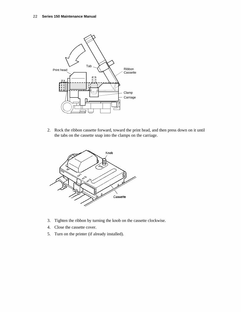
ORIGINAL FORMS COMPENSATION ASSEMBLY(MODEL 153)
1. Remove the forms compensation assembly. (See page 41).
2. Remove the two nuts (4) from the back of the forms compensation frame (1). The plateninsert (3) is now free.
3. Release the ‘E’ ring keepers (5), and remove the two bearings (6) from each end of thepressure roller (2).
4. Remove the forms compensation plate (9).
5. Remove the pressure roller (2).
6. Pull the bearing (7) off the right side of the forms compensation frame (1).
Note:
Do not remove the pin (8).

Series 150 Maintenance Manual44
REDUCED-SOUND FORMS COMPENSATIONASSEMBLY
1. Remove the forms compensation assembly. (See page 41).
2. Release the ‘E’ ring keepers (5), and remove the two bearings (6) from each end of thepressure roller (2).
3. Remove the pressure roller (2).
4. Remove screws (4) from the right-hand (7) and left-hand (10) arms.
Note:
Do not remove the platen insert (3) or pin (8).

Assembly/Disassembly 45
ORIGINAL LINE FEED MOTOR AND GEARS2
2
1
4
6
5
3
Shown Removedfor Clarity
1. Separate the electronics base from the mechanism base. (See page 29).
2. Remove the line feed motor (1) by prying off the two retaining clips (2) holding the motor tothe electronics base (3).
3. Models 151 and 152 only. Pull off the idler gear (4) from the electronics base.
4. Model 153 only. Remove the cam shaft (5) from the clutch gearassembly (6), and remove the clutch gear assembly from the electronics base. Mark the sideof the clutch gear that was facing the electronics base.
Model 153 Installation Note:
Model 153 only. After installing the clutch shaft and clutch gear assembly, check the clutch gearorientation. Apply light pressure to the clutch gear assembly, and turn the clutch shaft. Turningthe clutch shaft from top to back should turn the clutch gear. When turning the clutch shaft fromtop to front, the clutch gear should not rotate.

Series 150 Maintenance Manual46
REDUCED-SOUND LINE FEED MOTOR AND GEAR1
1
2
4
3
1. Separate the electronics base from the mechanism base. (See page 29).
2. Remove the line feed motor (1) by prying off the two retaining clips (2) holding the motor tothe electronics base (3).
3. Pull off the idler gear (4) from the electronics base.

Assembly/Disassembly 47
CASH DRAWER HARNESSES
14
3
2
1. Separate the electronics base from the mechanism base. (See page 29).
2. Disconnect Cash Drawer Harness #1 (1) from connector CN11 on the controller board (2).
3. Pull the harness up and out of the electronics base (3).
4. Disconnect Cash Drawer Harness #2 (4) from connector CN12 on the controller board (2).
5. Pull the harness up and out of the electronics base (3).

Series 150 Maintenance Manual48
PARALLEL/SERIAL COMMUNICATION PC BOARDS5
1
1
2
4
3
1. Separate the electronics base from the mechanism base. (See page 29).
2. Remove the cash drawer harnesses. (See page 46).
3. Unscrew the two screws (1) holding the mounting plate (2) to the electronics base (3).
4. Pull the mounting plate, with the communications board (4) attached, out of the back of theelectronics base.
5. Unscrew the two jack screws (5). Separate the communications board from the mountingplate.
1

Assembly/Disassembly 49
CONTROLLER PC BOARD1
2
2
2
3
4
1. Separate the electronics base from the mechanism base. (See page 29).
2. Remove the line feed motor. (See page 44).
3. Remove the cash drawer harnesses. (See page 46).
4. Disconnect the DC power harness (1) from connector CN10 on the controller board (3).
5. Unscrew the three screws (2) holding the controller board to the electronics base (4).

Series 150 Maintenance Manual50
POWER SUPPLY
1
5
4
4
4
42
3
1. Separate the electronics base from the mechanism base. (See page 29).
2. Disconnect the DC power harness (1) from the connector CN2 on the power supply (3).
3. Disconnect the power supply switch harness (2) from the connector CN1 on the powersupply (3).
4. Unscrew the four screws (4) holding the power supply (3) to the electronics base (5).

Assembly/Disassembly 51
AC INLET AND AC SWITCH
3
51
2
4
6
7
1
Power SupplySwitch Harness
Black
White
Green
Reference Wire Orientation
1. Remove the power supply. (See page 50).
2. Unplug the wires from the power switch assembly (1).
3. Remove the power switch assembly (1) by squeezing the tabs on the sides of the switch andpushing it out of the electronics base (2).
4. Unscrew the nut (3) holding the ground wire (4) to the stud (7) on the electronics base (2).Remove the lock washer (5) from the stud.
5. Remove the AC inlet assembly (6) by squeezing the tabs on the top and bottom of theassembly.
1
Power SupplySwitch Harness

Series 150 Maintenance Manual52
Troubleshooting 53
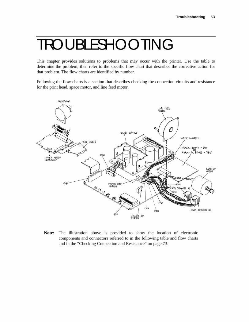
TROUBLESHOOTINGThis chapter provides solutions to problems that may occur with the printer. Use the table todetermine the problem, then refer to the specific flow chart that describes the corrective action forthat problem. The flow charts are identified by number.
Following the flow charts is a section that describes checking the connection circuits and resistancefor the print head, space motor, and line feed motor.
6
Note: The illustration above is provided to show the location of electroniccomponents and connectors referred to in the following table and flow chartsand in the “Checking Connection and Resistance” on page 73.

Series 150 Maintenance Manual54
DETERMINING THE PROBLEMWhen the Problem Occurs Description of Problem Refer to
Flow Chart
Switches or lights do not function on the keypad, andthe carriage does not move.
1
Carriage does not move, and power LED is lit. 2
Carriage does not operate normally; runaway,vibration, and incomplete homing occur.
3
Trouble at Power On
Carriage homes normally, but indicator display doesnot operate normally.
4
Spacing or printing does not occur. 5
Spacing operates normally, but printer does not print. 6
Printer stops printing. 7
Wrong characters are printed or some characters arenot printed.
8
Some dots do not print. 9
Trouble During Data
Reception or Printing
Print is not dark enough. 10
Receipt does not line feed. 11Forms Handling
Validation is not performed. 12

Troubleshooting 55
Is AC cordfully seated?
Is primarywiring loose or
broken?
1
Is secondarywiring loose or
broken?
Replace powersupply.
Voltages now
present?
End
Yes
No
No
Yes
Is AC switchdamaged or
open?
No
No
Yes
Yes
Yes
No 2
Repair/replacesecondary wiring
harness.
Replace AC switch.
Repair/replaceprimary wiring
harness.
Reseat AC powercord.

Series 150 Maintenance Manual56
2
Yes
No
Yes
No
No
No
Yes
No
Replace space motor.
Yes
Replace the spacerack.
No
Yes
No
Replace fuse.
Yes
No
Yes
Yes
2-2
When the power isturned on, the
carriage does notmove.
Do LEDsilluminate?
Can thecarriage be moved
easily byhand?
Remove theribbon cassette.
Is thecarriage cabledamaged orunplugged?
Replace/reseat the
carriage cable.
Can thecarriage be
moved easily byhand?
Replace the ribboncassette.
Is +40Vpresent at
emitter of Q14? Isthe space rack
okay?
Is fuse,F2, on the
controller boardopen?
Replace thecontroller board.
Remove the ribbonfeed gear assembly.
Replace the ribbonfeed gear assembly.
Canthe carriage
be moved easily byhand?

Troubleshooting 57
3
Runaway?
Replace controllerboard.
Vibration?
Replace controllerboard.
Yes
No
Yes
End
Yes
Yes
No
Isthe ribbon
feed assemblyattachedcorrectly?
Is carriagecable broken or
unplugged?
Replace space motorassembly.
Yes
No
Reassemble.
Replace/reseatcarriage cable.
No
YesIs printeroperationnormal?
No
No Proceed to 2-2.
When power is turned on, carriage operation isabnormal; runaway, vibration, or incomplete
homing occurs.
Arephase A&B
being output to U3 pins75, 76 on controller
board?

Series 150 Maintenance Manual58
4
When the power is turned on thehoming operation is normal, but the
READY LED is off.
No
Is paperinstalled in
printer?
Yes
Check to see ifpaper out flag
is blocking sensor.
No
Install paper.
Yes
No
Refer to Table 2FAULT INDICATORS.
Alarm LED?
Flashing alarmprinter fault?
Flashing alarm.

Troubleshooting 59
5
During data reception, neither carriagemovement nor printing occurs.
Verify that data isbeing transmitted to
the printer.
Can self-test beperformed?
Replace controllerboard.
No
Yes
Is interfacecable connected
correctly?
Reconnect interfacecable.
No
Is printerinterface
configuredcorrectly?
Yes
Replace thecontroller board.
Run configurationroutines.
No
Yes

Series 150 Maintenance Manual60
6
During data receptionand printing, carriagemotion is normal but
nothing prints.
Replace print head.
Is printoperationnormal?
Yes
End
Is ribbbonfeed assembly
attachedcorrectly?
Is carriagecable broken?
Yes
Reassemble.
Replace carriage cable.
No
Yes
No
Is the contactpin of print head
connectordeformed?
No
Replace controllerboard.
No
Replace the connector.Yes
6A

Troubleshooting 61
7
Yes
Yes
No
Yes
No
No
Are anyLED’s
flashing?
During data reception and printing,printing stops.
Refer to Table 1 LEDIndicators.
Reconnect theinterface cable.
Is the interfacecable connected
securely?
Replace the print head.
End
Replace controllerboard.
Is printeroperation normal?

Series 150 Maintenance Manual62
8
Wrong characters are printed, orsome characters are not printed.
Is interfacecable connected
properly?
Does self-testprint normally?
Is printerconfiguredcorrectly?
No Replace controllerboard.
Yes
Yes
Connect the cableproperly.
No
Replace controllerboard.
Yes
No Run configurationutility.

Troubleshooting 63
9
Some dots are notprinted.
Is the ribbonproperly
seated?
Remove theprint head.
Are any pinsbroken or
misaligned?
Check resistance ofthe print head coil.
Is resistanceapproximately
20 ohms?
Proceed to 6A.
Seat the ribbon.
Replace theprint head.
No
Yes
No
Yes
Yes
No

Series 150 Maintenance Manual64
10
Print is not darkenough.
Is the ribbbonfeed operating
properly?
Is ribbon wearexcessive?
Is head gapset correctly?
Are powersupply
voltagescorrect?
Is printeroperationnormal?
Replace ribboncassette.
Is operationnormal?
ENDReplace ribbon feed
gear assembly.
No No
YesYes
No
Yes
Yes
Yes
Replace controllerboard.
No
Replace powersupply.
No
No
Replace ribboncassette.
Yes
Adjust head gap.
Replace print head
END

Troubleshooting 65
11
Is paperinstalledproperly?
Is receipt feedstep motorplugged in?
Check resistance ofstep motor windings.
Bind in paperfeed gear
train?
Replace controllerboard.
Yes
Yes
Yes
Install paper correctly.
Reconnect motor tocontroller board.
Replace paper feedstep motor.
No
Correct bindcondition.
Yes
No
No
No
Receipt feed is notperformed.
Is resistance 7.0ohms?
Series 150 Maintenance Manual66
12
No
Yes
Yes
No
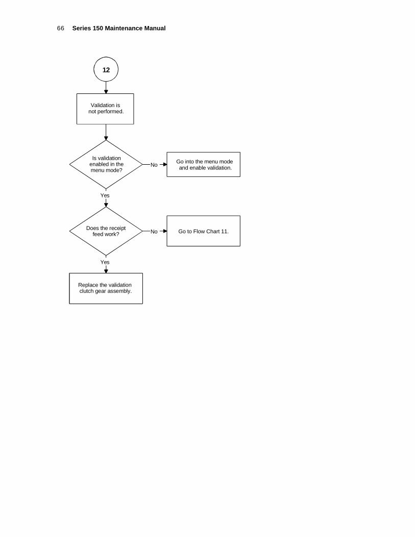
Validation isnot performed.
Is validationenabled in themenu mode?
Go into the menu modeand enable validation.
Does the receiptfeed work?
Replace the validationclutch gear assembly.
Go to Flow Chart 11.

Troubleshooting 67
OPERATING THE KEYPAD
READY ALARM POWERRESUME RELEASE FEED
The keypad contains three buttons and three indicator lights for easy operation. The AC powerswitch is on the left rear side of the printer. Take a few minutes to become familiar with thekeypad so that if something unexpected happens, you will be prepared.
ButtonsThe printer includes three buttons and a power switch, which have the following functions.
FEED ButtonThe FEED button advances receipt/journal paper.
RELEASE ButtonThe RELEASE button is used on printers with validation capability. This button opensand closes the Forms Compensation Assembly, allowing forms to be removed if a jamoccurs.
RESUME ButtonThe RESUME button has two functions.
1. Places the printer on-line after a paper loading operation has been completed.
2. After a printer fault has occurred, depress the RESUME button, and the alarm LEDwill display the error code. (Refer to the Programmer’s Guide for details.)
Note: When the printer is reinitialized, all printer functions return totheir default settings (as if the printer were just turned on) and anydata stored in the print buffer is lost. In this case, you may need toreenter the current transaction.

Series 150 Maintenance Manual68
AC Power SwitchThe AC power switch turns on the printer and puts it on-line. (READY light ON; ALARMlight OFF; POWER light ON).
Note: The printer takes about 1.5 seconds to begin operation.
INDICATOR LIGHTSThere are three indicator lights: READY, ALARM, and POWER. The READY and POWERlights are green. The ALARM light is red.
The printer can be in any of the following states:
STATE READYGreen
Indicator
ALARMRed
Indicator
POWERGreen
Indicator
1. ReadyThe printer is ready to receivedata and print.
ON OFF ON
2. Printer Not Ready (off-line) OFF OFF ON
3. Ready but waiting for a form ON Flash ON
4. Out of Paper OFF ON ON
5. Menu Mode Flash OFF Flash
6. Test Mode Flash OFF ON
7. Printer Fault OFF Flash ON
8. Printer Failure OFF OFF OFF
9. Watchdog Fault (Printer Resets)
Table 1 LED Indicators

Troubleshooting 69
PRINTER FAULT INDICATORSIf the printer indicates printer fault, the error is not recoverable. The printer must be restartedand may lose information. To aid in printer troubleshooting, the RESUME key will activate anextended diagnostic indication. This will blink the status indicator a number of times. Thenumber of blinks indicates the fault.
These errors are as follows:
Faults while in operation
1 Motor move time-out
2 Motor move retry fault
3 Motor move fault (Moved in wrong direction)
4 Space motor locked
5 Motor homing fault
6 Motor acceleration fault
7 Printing fault
8 Fault while centering
9 Forms compensation fault
Faults during Level 0 diagnostic
10 ROM check-sum failure
11 RAM failure
12 Configuration EEPROM failure
13 Processor test fault
14 EEPROM Check-sum failure
Faults that can happen any time
15 Firmware control fault (Loss of program control)
16 Cutter option fault
Table 2 Fault Indicators
After the fault code is displayed, the printer can be restarted by pressing the RESUME andRELEASE buttons simultaneously.
If the EEPROM check-sum fault occurs (Fault Code 14), the EEPROM can be set to default bypressing the RESUME and LF buttons simultaneously. The printer will be functional but mustbe reconfigured. This procedure is only to allow reconfiguration and not to recover printerfunction in the field.
If the indication is “Printer Failure,” the printer controller is not running and is being held inreset. If this failure occurs, the printer is not functional and should be serviced.

Series 150 Maintenance Manual70
If the printer appears to go through a power cycle by itself, the hardware watchdog has detecteda fault. This fault is generally a hardware failure or an external interference. If the fault ishardware, the printer will continue to cycle through its diagnostics and then reset. If thishappens, the printer must be serviced. If the fault is caused by external interference likeelectrostatic discharge (ESD), the printer will generally recover by itself. (NOTE: The parallelport INIT pin causes a soft reset.)
PRODUCT SELF-TESTSThe Series 150 Printer features several levels of self-test. At power up the printer always runsLevel 0 Diagnostics. The Level 0 Diagnostics check the printer for proper operation. After theLevel 0 Diagnostics are complete, the printer checks the keypad for a request to enter one of theExtended Diagnostic Tests, if a request is not found the printer enters normal operations.
Level 0 DiagnosticsLevel 0 Diagnostics always run at power up and perform the following tests.
TEST READYGreen Indicator
ALARMRed Indicator
POWERGreen Indicator
1. Reset ON ON ON
2. CPU Test and ROM Test OFF OFF ON
3. External RAM Test ON OFF ON
Extended DiagnosticsThe Extended Diagnostics allow the printer to enter one of several modes.
♦ Self-test allows testing of various modes of the printer.
♦ Configuration Mode enables manual configuration of the printer.
♦ Hex Dump prints the hex value sent to the printer from the host.
♦ Remote Configuration Mode allows remote configuration of the printer by a personalcomputer running the CFG150 program.

Troubleshooting 71
Self-testThe Self-test offers the six tests listed below.
♦ Receipt Test prints a sample receipt.
♦ Validation Test performs a sample validation.
♦ Self-test checks the printer’s print capabilities.
♦ Mechanical Test Mode checks the forms compensation mechanism.
♦ Rolling ASCII Test prints a continuous printout and is useful for testing the printerreliability and ribbon life.
♦ Burn-in Test is part of the production process. It checks that the printer isfunctioning correctly and provides an initial burn in.
To start the Self-test, follow the steps listed below.
1. Turn off the printer.
2. Press and hold the RESUME button while turning on the printer.
When the printer starts printing, release the RESUME button.
The software revision information and instructions are printed. When the printerstops printing, the first selectable test is printed at the bottom of the receipt.
3. Press and release the RELEASE button until the test you would like to run isprinted.
4. Press the RESUME button at the start of the test.
5. To exit the self-test, turn the printer off and then back on.
Configuration ModeThis mode allows manual configuration of the printer. The printer requires properconfiguration to run correctly with the host personal computer or after the Level 0Diagnostic detects an invalid EEPROM. When an invalid EEPROM is detected, theEEPROM is initialized; a default configuration is loaded; and the printer needs to bereconfigured to run correctly with the host personal computer.
Note: Manual configuration may be locked by remote configuration. Inthis case, enter the Remote Configuration Mode. (See page 73).
For a compete list of Configuration Options and recommended settings, refer to theProgrammer’s Guide.

Series 150 Maintenance Manual72
To start the Configuration Mode, follow the steps listed below.
1. Turn off the printer.
2. Press and hold the FEED and RESUME buttons while turning on the printer.
When the printer starts printing, release both buttons.
The software revision information and instructions are printed. When the printerstops printing, the first selectable test is printed at the bottom of the receipt.
3. Press and release the RESUME button until the group you would like to change isprinted.
4. Press and release the RELEASE button until the correct option is printed.
5. Press the RELEASE and RESUME buttons to select the option.
6. Repeat Steps 3 and 5 until all the correct options are selected.
7. Verify the current configuration by pressing and releasing the RESUME and FEEDbuttons. This will print a list of all the current settings.
8. To save the configuration, repeat Step 3 until “Save Configuration” is printed.
Press and release the RELEASE button until “Yes” is printed.
Press and release the RELEASE and RESUME buttons to select “Yes.”
The current configuration is saved, and the printer is ready for normal operations.
Hex Dump ModeThis mode is used to diagnose communication problems with the printer. As the printerreceives information, the information is converted to HEX/ASCII code and printed onthe receipt. Refer the Programmer’s Guide for more information about the hex dumpformat.
To start the Hex Dump Mode, follow the steps listed below.
1. Turn off the printer.
2. Press and hold the RESUME and RELEASE buttons while turning on the printer.
When the printer starts printing, release both buttons.
3. To exit the Hex Dump Mode, turn the printer off and then back on.

Troubleshooting 73
Remote Configuration ModeThis mode allows a remote host personal computer to setup, display configurationinformation, and test the Series 150 Printer and requires the CFG150 Program berunning on a personal computer connected the printer. Refer to the CFG90/150 User’sGuide for detailed information about the CFG150 Program.
To run the Remote Configuration Mode, follow the steps listed below.
1. Connect the printer to a host personal computer using either the serial or parallelport.
2. Load the configuration program into the personal computer, and enter configurationmode.
3. Turn off the printer.
4. Press and hold the FEED and RELEASE buttons while turning on the printer.
After the Level 0 Diagnostics, the printer will enter CFG150 Mode.
5. To exit the Remote Configuration Mode, turn the printer off and then back on.
CHECKING CONNECTIONS AND RESISTANCEPrint HeadThe following illustration shows the connection circuit for the print head and the rear of theprint head. The resistance should be approximately 20 ohms.
Pins at Connection Signals Pins onPrinthead
Rear of Print head
Common
Wire #1
Wire #2
Wire #3
Wire #4
Wire #5
Wire #6
Wire #7
Wire #8
Wire #9
5, 6, 7
14
13
1
12
2
11
1
10
4
To check the circuit of wire number one of the print head, use Pin 5, 6, 7 on the print headand measure with a meter to Pin 14 at Location A. The resistance should read 20 ohms.

Series 150 Maintenance Manual74
Space Motor AssemblyThe following illustration shows the connection circuit for the space motor assembly and thepins on the space motor. The resistance should be approximately 21 ohms between Pads 17and 16, 16 and 18, and 17 and 18 on the space motor.
Pins at Connection Signals Pins on Space Motor
V
U
W
A
B
15
14
16
Line Feed MotorThe following illustration shows the connection circuit for the line feed motor. Theresistance of each coil should be approximately 70 ohms between Pins 3 and 2, 2 and 1, 4and 5, and 5 and 6 on the line feed motor.
Pins at Connection Signals Pins on Line Feed Motor
Phase One
Common
Phase Three
Phase Two
Common
Phase Four
3
2
1
4
5
6

Appendix A: Theory of Operation 75
APPENDIX A: THEORY OFOPERATION

Series 150 Maintenance Manual76
ELECTRICAL OPERATIONCircuit Operation
The electrical section of the printer consists of the components shown in the above diagram.
The control board contains the microprocessor, its peripheral circuits, and all associateddrive circuits for the print head, line feed motor, journal take-up motor, cash drawers, andsensors.
The printer control signals from the host system (personal computer or terminal) arebrought directly to the control board from the rear panel on the printer.

Appendix A: Theory of Operation 77
MICROPROCESSOR AND PERIPHERAL CIRCUITSMicroprocessor (U1: 80C154)The microprocessor is the nucleus of the control board. It controls the peripheral circuits.
Program ROM (U4)The program ROM stores the control program for the printer.
Program RAM (U2)The RAM stores printer configuration information.
RAM (U5)The RAM stores data such as received print data.
LSI (M7U042-026)The M7U042-026 motor control LSI has the following functions:
♦ Space Motor Speed Control,
♦ Dot Timing Generation,
♦ I/O (input and output) Ports,
♦ Address Latch, and
♦ Address Decoder.
Space Motor Speed Control FunctionThe space motor speed control function accelerates and decelerates the space motor inaccordance with commands from the microprocessor and controls the space motor speedin each printing mode.
Dot Timing Generation FunctionThe dot timing generation function generates the dot timing signal (/IPT), synchronizedwith the printing speed in accordance with output signals (PHASE A, B) of the encoderon the space motor, and sends this timing information to the microprocessor.
I/O PortsThe input and output ports control signals in accordance with the commands input fromthe microprocessor.
Address LatchThe address latch fastens the low-order 8-bits of the address (A0 to A7). These bits areused as an address for read/write operations with peripheral devices.

Series 150 Maintenance Manual78
Address DecoderThe address decoder decodes the address signal (A11 to A15) and sends the/RAMSEL4 signal.
INITIALIZATIONThe printer is initialized when the power is turned on or when the parallel interface signal, I-PRIME, is received from the host computer.
Initialization is started with the RSTOUT signal output from the reset circuit to reset U1(microprocessor) and U3 (LSI).
When resetting is complete, the program starts with mode settings of U1, U3, and U5, memory(ROM and RAM) check, AM initialization, and then carriage homing. The program finallyestablishes the interface signals (output of ACK signal, BUSY signal, etc.), lights the selectindicator, and informs the host system that the printer is ready for data reception (in the datareception wait state). This completes the initialization routine.
INTERFACE CONTROLParallel Interface
The data from the interface is input through the connector (CN6), and the interface LSI (U3:7U042-026) latches this input data in sync with the /STB signal.
The BUSY signal is on while the data is being processed. When the processing is complete,the BUSY signal is turned off, and an /ACK signal is sent to request more data.
Serial InterfaceThe data from the interface is input through the connector (CN7) and the serial drive (U6:DS14C238) with data I/O to the microprocessor.

Appendix A: Theory of Operation 79
PRINT HEAD DRIVE CIRCUIT
The print head drive circuit drives the head magnets corresponding to the HEAD DATA 1 to 9signals in accordance with the HEAD-ON signal, forcing the print head to print characters.
When the HEAD-ON signal goes high, the RC integrator (R576 and C524) determines the headdrive time. The integrator lengthens the drive time if the drive voltage (+40) lowers, and shortensthe drive time if the voltage rises. The result is a consistent print wire impact force.
CARRIAGE DRIVESpace Motor Control
The motor control LSI (U3: M74042-026) simultaneously outputs the space motor phasesignals (SP-U, SP-V, and SP-W) in accordance with the spacing command from themicroprocessor and the overdrive signal (SPD-A).

Series 150 Maintenance Manual80
The SPD-A signal is a fixed-period pulse signal whose pulse width is controllable by theprogram. It is used to control the motor drive time.
The SP ON/OFF signal is output during acceleration and deceleration when greater torqueis required.
The motor driver (MTDV) drives the space motor in accordance with these signals. Pins 9and 11 of the MTDV are for the overvoltage (9) and overcurrent (11) protective circuits.
Slit Encoder
Space motor PHASE-A and PHASE-B signals are generated by a photosensor and a slitdisk. The control LSI (U3: M7U042-026) frequency divides the edge pulse signals at a ratedependent upon the print pitch and outputs the /IPT signal to provide dot-on and carriageposition timing.

Appendix A: Theory of Operation 81
LINE FEED
The line feed motor is locked with the +5 voltage while it is stopped. When line feeding, the linefeed motor is driven by the +40 supply in accordance with the LF OVD signal.
ALARM CIRCUITSDrive Circuit Fault Alarm CircuitThe drive circuit fault alarm circuit is a protective circuit that makes the power supplyshutdown when a fault occurs in the print head drive circuit, space motor drive circuit, linefeed motor drive circuit, or one of their peripheral circuits.
The circuit operates by monitoring the drive time using the HDALM, SPALM, and LFALMsignals interlocked with the overdrive signal of each drive circuit. If the drive time of anycircuit exceeds the specified time, the drive circuit fault alarm outputs an ALM signal to thepower supply.
In the event that there is a component failure in the drive circuit, a fuse is located on thecontroller board to prevent further damage.
Fuse (F2) will blow if there is a component failure in the space motor drive circuit.
Head Overheat Alarm CircuitIn order to protect the head coils, the head overheat alarm circuit monitors the headtemperature using the built-in thermistor of the print head.
If heavy-duty printing is performed continuously for a long time, the print head temperaturerises. When the print head temperature reaches approximately 100°C, a head overheat alarmoccurs. At this point, the print mode is switched from bidirectional to unidirectional toreduce the duty-cycle which in turn lowers the temperature of the print head. When the printhead temperature returns below the alarm detection temperature, bidirectional printing isresumed.

Series 150 Maintenance Manual82
When the temperature of the print head rises during operation, the resistance of thethermistor lowers, and the potential of the comparator’s (U10) negative input lowers toinvert the comparator’s output, causing the HEAD TEMP signal to be output to the controlLSI.
Print time slows until the temperature falls back below the threshold.
Note: This is a normal operation and will not cause any data loss. Do notturn off the printer, or data loss will result.
POWER SUPPLYThe power supply is a self-contained, integrated, switching power supply. The internal fuse (F1)located on the power supply will blow if the supply has an internal fault.
The power supply has the following outputs, +5 VDC, +12 VDC, and +40 VDC, and an alarmsignal input.
AC INPUTThe AC input connector and power switch are located on the back of the printer.
MECHANICAL OPERATIONPrint Head Mechanism and OperationThe print head is spring-loaded, using a permanent magnet, and can be easily removed orinstalled. The print head is mounted on a carriage that runs parallel to the platen and isconnected with the control circuit via the circuit board.
The print head consists of the following items:
♦ Wire guide,
♦ Wires,
♦ Armature assembly,
♦ Yoke,
♦ Springs,
♦ Spacer,
♦ Magnet assembly,
♦ Thermistor, and
♦ PC board.

Appendix A: Theory of Operation 83
Print Head OperationWhen the print head is in the nonprinting state, each armature is attracted by the permanentmagnet, and the springs holding the armatures are compressed by the thickness of thespacer. Therefore, the print wires, which are fastened to the individual armatures, are heldretracted within the wire guide.
When signals corresponding to a character to be printed are detected by the control circuit,currents flow through the corresponding coils to nullify the magnetic flux generated by thepermanent magnet assembly. With the magnetic flux nullified, the print wire coil armaturesare driven toward the platen by the force of the armature springs. The print wires, fastenedto the armatures, are ejected from the tip of the wire guide and strike the paper through theribbon.
After the character is printed, the magnetic flux of the permanent magnet assembly attractsthe armatures again, which retract the print wires back into the wire guide.
The print head has a built-in thermistor to prevent the coils from overheating.
SPACE MECHANISM AND OPERATIONThe spacing operation is performed by the DC motor driving the carriage frame, which is guidedby the carriage shaft mounted parallel to the platen. The DC motor is mounted on the bottom ofthe carriage frame.
The space mechanism consists of the following items:
♦ DC motor with motor gear,
♦ Carriage frame,
♦ Carriage shaft,
♦ Space rack,
♦ Slit sensor, and
♦ Slit disk.
The carriage, with the print head and space motor mounted on it, moves parallel to the platenalong the carriage shaft. As the space motor rotates counterclockwise, the motor gear is drivento the right along the space rack, and as a result, the carriage is also driven to the right.
The spacing mechanism is designed such that when the space motor rotates one turn, thecarriage frame moves 0.8 inch (20.32 mm).
Motor rotation also rotates the slit disk, and the slits pass through the slit sensor. The position ofthe carriage frame can be obtained by counting the number of slits detected by the slit sensor.

Series 150 Maintenance Manual84
RIBBON FEED MECHANISM AND OPERATIONThe ribbon feed mechanism feeds the ribbon synchronously with the spacing operation. Themechanism is driven by the space motor.
The ribbon feed mechanism consists of the following items:
♦ Ribbon feed gear assembly,
♦ Ribbon gear (Space motor), and
♦ Ribbon cartridge.
Ribbon Feed OperationAs the space motor rotates, the ribbon gear on the space motor shaft also rotates to movethe drive gear in the ribbon cartridge via the ribbon feed gear assembly. As a result, theribbon is fed.
During bidirectional printing, the ribbon gear rotational direction reverses every time thecarriage reverses direction. When this happens, the gears in the ribbon feed gear assemblyswitch the rotational direction to feed the ribbon in a fixed direction.
Ribbon CartridgeA one-way feed endless ribbon is used. Ink is replenished by the built-in ink tank in theribbon cartridge.
RECEIPT FEED MOTORThe printer feeds paper by rotating the feed roll shaft assembly, which is driven by the receiptfeed motor through a speed reduction gear. The paper is pinched between the feed roll shaft andpressure roll shaft (part of the forms compensation assembly).
The receipt paper feed mechanism consists of the following items:
♦ Stepper motor with gear,
♦ Receipt feed roll shaft assembly, and
♦ Forms compensation assembly.
The receipt-paper feed-stepper motor is mounted on the right side of printer assembly, and itsrotation is transmitted through the receipt feed motor drive train.
PAPER EXHAUSTPaper is sensed in the printer by a paper-out flag assembly. When the flag trips the sensor on thePC board, the printer goes off-line, and the ALARM LED lights.

Appendix B: Parts Lists 85
APPENDIX B: PARTS LISTS

Series 150 Maintenance Manual86
PACKING MATERIALS/PUBLICATIONS
2
3
2
1
4
6
MAINTENANCEMANUAL
PROGRAMMER’SGUIDE
OPERATOR’SGUIDE
5
7

Appendix B: Parts Lists 87
ITEM NO. PART NO. QTY DESCRIPTION
15-9306 1 Packset, Ithaca (complete)
15-9308 1 Packset, OKI Europe (complete)
15-9307 1 Packset, M150 White
1 90-7579 1 Carton - White
2 15-01834 1 Foamset - M150
3 100-7565 1 Ribbon Cassette (Black)
3 100-7559 1 Ribbon Cassette (Purple)
4 06-0561 1 110V Power Supply Cable
4 06-0806 1 230V Power Supply Cable
5 15-9321 1 Publications Kit, (includes the Operator’s Guide)
6 15-9320 1 Maintenance Manual
7 100-7961 1 Programmer’s Manual
8 90-7568 1 Retainer - Print head
9 98-01902 1 Plastic bag

Series 150 Maintenance Manual88
PRINTER ASSEMBLY
1 3
4
22

Appendix B: Parts Lists 89
ITEM NO. PART NO. QTY DESCRIPTION
1 See ‘Paper Cover’ on page 90.
2 See ‘Cassette Cover without Knife’ on page 91.
2 See ‘Cassette Cover with Knife’ on page 92.
3 15-9441 1 Label (Ithaca)
3 15-9376 1 Label (UTC)
3 15-9377 1 Label (OKI Latin)
3 15-9723 1 Label (OKI Europe)
3 15-9902 1 Label (Telecom)
4 90-6415 1 Spindle - Take-up

Series 150 Maintenance Manual90
PAPER COVER
2
1
2
3
4
5
ITEM NO. PART NO. QTY DESCRIPTION
1 15-8260 1 Cover - Standard Paper (Lt. Tan)*
1 15-9355 1 Cover - Knife Paper (Lt. Tan)*
1 15-9340 1 Cover - Paper With Journal Lock (Lt. Tan)*
2 98-1284 1 Lockset
3 06-1269 1 Extension Journal Lock
4 98-0707 1 Screw - ¼ x 28 x 1”
5 15-9405 1 Label - Paper loading without knife but with bail
5 15-9707 1 Label - Paper loading with knife and bail
5 15-9946 1 Label - Paper loading without knife and bail
5 15-9947 1 Label - Paper loading with knife without bail
*When ordering a Paper Cover Assembly, also order a Paper Loading Label (Item 5).

Appendix B: Parts Lists 91
CASSETTE COVER WITHOUT KNIFE
ITEM NO. PART NO. QTY DESCRIPTION
15-01495 1 Cover - Cassette Standard Assembly (Lt. Tan)*
15-01496 1 Cover - Cassette OKI Europe Assembly (Lt. Tan)*
1 15-8252 1 Cover - Hinged Cassette (Lt. Tan)
1 15-01329 1 Cover - OKI Europe Cassette (Lt. Tan)
2 15-8077 1 Tear Bar
5 98-2052 2 Screw - #6-20 x 0.375 PHPS PHD
6 15-9706 1 Label - Cassette Loading
*When ordering a Cassette Cover Assembly, also order a Cassette Label (Item 6).

Series 150 Maintenance Manual92
CASSETTE COVER WITH KNIFE
ITEM NO. PART NO. QTY DESCRIPTION
15-01490 1 Cover - Knife Cassette Assembly (Lt. Tan)*
1 15-01485 1 Cover - Knife Cassette (Lt. Tan)
2 15-9776 1 Label - Cassette Loading
*When ordering a Cassette Knife Cover Assembly, also order a Cassette Label (Item 2).
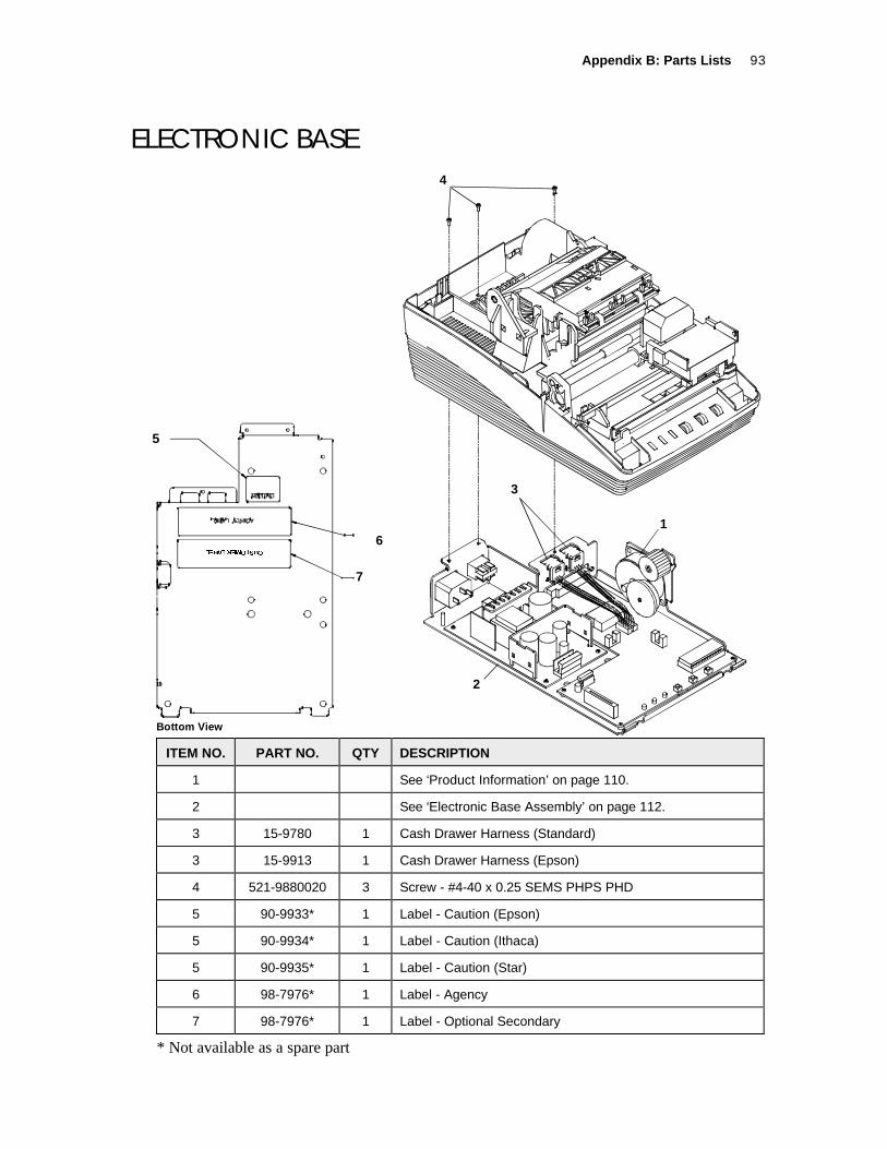
Appendix B: Parts Lists 93
ELECTRONIC BASE4
3
1
2
Bottom View
7
6
5
ITEM NO. PART NO. QTY DESCRIPTION
1 See ‘Product Information’ on page 110.
2 See ‘Electronic Base Assembly’ on page 112.
3 15-9780 1 Cash Drawer Harness (Standard)
3 15-9913 1 Cash Drawer Harness (Epson)
4 521-9880020 3 Screw - #4-40 x 0.25 SEMS PHPS PHD
5 90-9933* 1 Label - Caution (Epson)
5 90-9934* 1 Label - Caution (Ithaca)
5 90-9935* 1 Label - Caution (Star)
6 98-7976* 1 Label - Agency
7 98-7976* 1 Label - Optional Secondary
* Not available as a spare part
5

Series 150 Maintenance Manual94
CUTTER
ITEM NO. PART NO. QTY DESCRIPTION
1 15-02028 1 See ‘Knife Assembly’ on page 95.
2 15-8052 1 Mount - Right Knife Bracket
3 15-8051 1 Mount - Left Knife Bracket
4 98-7608 3 Screw - #4 Plastic Thread Forming
5 15-9967 1 Spring - Extension

Appendix B: Parts Lists 95
KNIFE ASSEMBLY

Series 150 Maintenance Manual96
ITEM NO. PART NO. QTY DESCRIPTION
15-02028 1 Standard Assembly - Knife
1 15-01254* 1 Frame - Knife
2 15-8121* 1 Guide - Knife
3 15-01323* 1 Plate - Knife
4 15-01325* 1 Blade - Moving (Sharp)
5 90-9673* 1 Gear - Knife 36 Tooth
6 90-9742* 1 Pin - Knife
7 15-01872* 1 Rod - Connecting
8 15-01326* 1 Slider - Knife
9 90-6080* 1 Stud -Knife
10 15-01189* 1 Film -Teflon
11 98-6083* 1 Retainer - E-ring
12 98-2052* 1 Screw - #6-20 x 0.375 PHPS PHD
14 98-6084* 1 Washer -Spring
15 90-9061* 1 PCB Assembly
16 15-9986* 1 Assembly - Knife Motor with Resistor
17 90-9182* 1 Gear - Compound
18 98-9951* 1 Screw - #0-80 x 5/16 SS Flat HD
19 98-9187* 1 Retainer -Wire
21 98-0621* 1 Nut - M3
22 15-01324* 1 Blade - Shear
* Not available as a spare part

Appendix B: Parts Lists 97
TAKE-UP MOTOR ASSEMBLY
1
2
3
4
5
ITEM NO. PART NO. QTY DESCRIPTION
1 15-9311 1 Assembly - Take-up Motor (includes Harness)
2 15-8306* 1 Harness - Take-up Drive
3 15-8066 1 Insert - Take-up Motor
4 15-02033 1 Gear
5 15-8210 1 Shaft - Take-up Gear
* Not available as a spare part

Series 150 Maintenance Manual98
SWITCH ASSEMBLY AND LIGHT PIPES
1
23
ITEM NO. PART NO. QTY DESCRIPTION
1 15-8030 1 Base - Filler (Light Tan)
2 15-8040 3 Button
3 15-8050 3 Light pipe - Keypad

Appendix B: Parts Lists 99
PRINT AND VALIDATION MECHANISM ASSEMBLIES

Series 150 Maintenance Manual100
ITEM NO. PART NO. QTY DESCRIPTION
1 15-9305* 1 See ‘Carriage Assembly’ on page 100.
2 15-8068 1 Shaft - Carriage
3 15-9966 1 Link - Ground
4 98-2112 1 Screw - M4x8 mm PHPS PHD SEMS
5 98-8130 1 Screw - #4-40 x 0.25 PLT PHPS
6 15-01826 1 Rail - Carriage
7 98-2014 1 Washer - M3 Flat
8 98-0621 1 Nut - M3 Hex with Lockwasher
9 R90-6056 1 Rack - Space
10 15-01186 1 Shaft - Feed
11 98-8073 2 Bearing - Flanged Nyliner
12 98-9324 1 Washer - Flat
13 520-9800104 1 Retainer - C-Ring 0.23 diameter
14 98-0897 1 Screw - M3x8mm PHPS PHD
15 15-01825 1 Retainer - Journal
16 15-02011 1 Bearing - Right Forms Compensation
17 15-02010 1 Bearing - Left Forms Compensation
18 98-7608 3 Screw - #4 Plastic Thread Forming
19 15-02017 1 Shaft - Forms Compensation
20 15-8108 1 Assembly - Clutch Gear
* Not available as a spare part

Appendix B: Parts Lists 101
CARRIAGE ASSEMBLY
ITEM NO. PART NO. QTY DESCRIPTION
15-9305* 1 Assembly - Carriage
1 R06-0574 1 Connector - Print head
2 R90-7337 1 Print head
3 R15-01837 1 Assembly - Ribbon Feed Gear Box
4 R90-7339 1 Rubber - Contact Pressure
5 R90-7340 1 Cable - Head
6 90-7431* 1 Assembly - Carriage Motor
* Not available as a spare part

Series 150 Maintenance Manual102
CARRIAGE MOTOR ASSEMBLY
ITEM NO. PART NO. QTY DESCRIPTION
1 R06-0575 1 Slider - OKI
2 98-7280 1 Assembly - Space Motor
3 R90-7341* 1 Roller - Carriage
4 R90-7342 3 Screw - Carriage
5 R06-0571 1 Clamp - Print head

Appendix B: Parts Lists 103
MECHANISM BASE (ORIGINAL FORMSCOMPENSATION ASSEMBLY)

Series 150 Maintenance Manual104
ITEM NO. PART NO. QTY DESCRIPTION
1 15-8109 1 See ‘Forms Compensation Assembly (Models 151 & 152)’ onpage 107.
1 15-8110 1 See ‘Forms Compensation Assembly (Model 153)’ on page108.
2 15-8208 1 Spring - Right
3 15-8209 1 Spring - Left
4 15-8055 1 Bail - Paper
5 15-8107 1 Flag - Paper Out
6 15-9183 1 Spring - Paper Exhaust
7 15-9797 2 Rod - Roller Support (Use with 3.25 Wide Paper Only)
8 15-9798 4 Roller - Paper Supply (Use with 3.25 Wide Paper Only)
9 15-9907 1 Flag - Validation
10 15-01197 1 Base (Light Tan)
11 15-8057 1 Bracket - Journal Lock (Models with journal lock only)
12 98-7608 2 Screw - #4 Plastic Thread Forming (Models with journal lockonly)
13 98-2482 1 Tape - Print head Cable
14 15-01173 asreq’d1
Kit - Spacer 2.75” Paper (includes 4 spacers 15-01173 and 8pieces of tape 90-9188)
14 90-9188 asreq’d2
Kit - Spacer 3.00” Paper (includes 2 spacers 15-01173 and 4pieces of tape 90-9188)
1 The required quantity is 4 for 2.75” paper. The required quantity is 2 for 3.00” paper.2 The required quantity is 8 for 2.75” paper. The required quantity is 4 for 3.00” paper.

Appendix B: Parts Lists 105
MECHANISM BASE (REDUCED-SOUND FORMSCOMPENSATION ASSEMBLY)

Series 150 Maintenance Manual106
ITEM NO. PART NO. QTY DESCRIPTION
1 15-02030 1 See ‘Reduced Sound Forms Compensation Assembly’ on page107.
2 15-02035 1 Spring - Right
3 15-02036 1 Spring - Left
4 15-8055 1 Bail - Paper
5 15-8107 1 Flag - Paper Out
6 15-9183 1 Spring - Paper Exhaust
7 15-9797 2 Rod - Roller Support (Use with 3.25 Wide Paper Only)
8 15-9798 4 Roller - Paper Supply (Use with 3.25 Wide Paper Only)
9 15-9907 1 Flag - Validation
10 15-02050 1 Base (Light Tan)
11 15-02031 1 Bracket - Journal Lock (Models with journal lock only)
12 98-7608 2 Screw - #4 Plastic Thread Forming (Models with journal lockonly)
13 98-2482 1 Tape - Print head Cable
14 15-01173 asreq’d1
Kit - Spacer 2.75” Paper (includes 4 spacers 15-01173 and 8pieces of tape 90-9188)
14 90-9188 asreq’d2
Kit - Spacer 3.00” Paper (includes 2 spacers 15-01173 and 4pieces of tape 90-9188)
1 The required quantity is 4 for 2.75” paper. The required quantity is 2 for 3.00” paper.2 The required quantity is 8 for 2.75” paper. The required quantity is 4 for 3.00” paper.

Appendix B: Parts Lists 107
ORIGINAL FORMS COMPENSATION ASSEMBLY(MODELS 151 AND 152)
ITEM NO. PART NO. QTY DESCRIPTION
15-8109 1 Assembly - M151/152 Forms Compensation
1 15-01162* 1 Frame - Forms Compensation
2 15-8225* 1 Roller - Pressure with Rubber
3 15-8230* 1 Platen with Insert
4 98-0621* 2 Nut - M3 Hex with Lock washer
5 98-8223* 2 Keeper - ‘E’ Ring
6 15-8221* 2 Bearing - Pressure Roller
7 15-01163* 2 Pin - 1” Roller
* Not available as a spare part

Series 150 Maintenance Manual108
ORIGINAL FORMS COMPENSATION ASSEMBLY(MODEL 153)
ITEM NO. PART NO. QTY DESCRIPTION
15-8110 1 Assembly - M153 Forms Compensation
1 15-01162* 1 Frame - Forms Compensation
2 15-8225* 1 Roller - Pressure with Rubber
3 15-8230* 1 Platen with Insert
4 98-0621* 2 Nut - M3 Hex with Lock washer
5 98-8223* 2 Keeper - ‘E’ Ring
6 15-8221* 2 Bearing - Pressure Roller
7 15-8204* 1 Bearing
8 15-01163* 2 Pin - 1” Roller
9 15-8222* 1 Plate - Forms Comp
* Not available as a spare part

Appendix B: Parts Lists 109
REDUCED-SOUND FORMS COMPENSATIONASSEMBLY
ITEM NO. PART NO. QTY DESCRIPTION
15-02030 1 Assembly - Forms Compensation (Reduced Sound)
1 15-02008 1 Center - Forms Compensation
2 15-8225* 1 Roller - Pressure with Rubber
3 15-02055 1 Platen - Steel
4 98-02040 4 Screw - #4 - 40 Hex HD
5 98-8223* 2 Keeper - ‘E’ Ring
6 15-8221* 2 Bearing - Pressure Roller
7 15-02007 1 Arm - Left Forms Compensation
8 15-01163* 2 Pin - 1” Roller
9 15-8222* 1 Plate - Forms Comp
10 15-02009 1 Arm - Right Forms Compensation
* Not available as a spare part

Series 150 Maintenance Manual110
ORIGINAL LINE FEED MOTOR AND GEARS2
2
1
4
6
5
3
Shown Removedfor Clarity
ITEM NO. PART NO. QTY DESCRIPTION
1 98-7970 2 Clip - Retaining
2 98-7847 1 Motor - OKI Line feed
3 15-8211 1 Gear - Idler (Models 151 & 152 Only)
4 15-8108 1 Assembly - Clutch Gear (Model 153 Only)
5 15-8200 1 Assembly - Cam Shaft (Model 153 Only)
6 50-1470 1 Gear Plus Stepper

Appendix B: Parts Lists 111
REDUCED-SOUND LINE FEED MOTOR AND GEAR
1
1
2
4
3
ITEM NO. PART NO. QTY DESCRIPTION
1 98-7970 2 Clip - Retaining
2 98-7847 1 Motor - OKI Line feed
3 15-8211 1 Gear - Idler (Models 151 & 152 Only)
4 50-1470 1 Gear Plus Stepper

Series 150 Maintenance Manual112
ELECTRONIC BASE ASSEMBLY
4

Appendix B: Parts Lists 113
ITEM NO. PART NO. QTY DESCRIPTION
1 15-01113 1 Base - Electronics
2 R15-9795 1 Assembly - PCB M150 Controller
3 98-9796 1 Supply - Universal Power
4 98-2033 1 Screw - Jack
5 90-7442 1 Assembly - Power Supply Switch
6 15-9143 1 Harness - DC Power
7 06-0553 2 Foot - Rubber
8 521-9880020 7 Screw - #4-40 x 0.25 SEMS PHPS PHD
9 15-9097 1 Assembly - AC Input Connector
10 525-9800002 1 Nut - Hex #4-40
11 98-0653 1 Lock washer - M3
12 15-9751 1 Foot - 2” Long Rubber
13 98-6614 1 Foot - 0.40 x 0.40 x 0.10 Rubber
14 15-9761 1 Insulator - PC Board
15 15-9696 1 Assembly PC Board - Serial (9-pin)
15 15-01327 1 PC Board - Serial (25-pin)
15 15-9695 1 Assembly PC Board - Parallel
17 15-8063* 1 Plate - Com PCB Mounting
* Not available as a spare part

Series 150 Maintenance Manual114

Appendix C: Schematics 115
APPENDIX C: SCHEMATICS
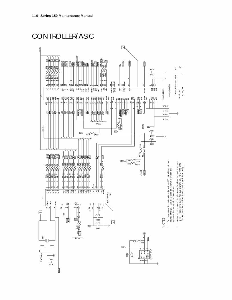
Series 150 Maintenance Manual116
CONTROLLER/ASIC

Appendix C: Schematics 117
MEMORY/RECEIPT MOTOR DRIVE

Series 150 Maintenance Manual118
SPACE MOTOR CONTROL

Appendix C: Schematics 119
HEAD CONTROL

Series 150 Maintenance Manual120
CONTROL INTERFACE

Appendix C: Schematics 121
CONTROL INTERFACE

Series 150 Maintenance Manual122
INTERFACE

Appendix C: Schematics 123
USB INTERFACE

15-9320 Rev. C 12/99