Embed Size (px)
Citation preview

Preliminary Design Report Portal Road Bridge over the North Inlet Structure No.: 0506.01 CDOT Project No. BRO‐M‐560‐003, Code 20096 PREPARED FOR
Town of Grand Lake P.O. Box 99 Grand Lake, CO 80447 October 2016

Preliminary Design Report | ii
General Information .................................. 1
Design Criteria .......................................... 2
Rehabilitation Alternatives ......................... 2 Construction Phase Traffic Control ........... 4 Schematic Construction Schedule ............ 6
Conclusion ................................................ 7 Appendix A: Engineer’s Opinion of Probable Construction Cost Appendix B: Utility Coordination Documents

Structure No. 0506.01 Portal Road Bridge BRO-M-560-003 Preliminary Design Report
Y:\Denver\151300S\00151386.00_Portal_Road\Office_Docs\Preliminary Design Report (working)\Portal Road Preliminary Design Report.docx
- 1 -
PRELIMINARY DESIGN REPORT: 1. GENERAL INFORMATION: Introduction: The Town of Grand Lake has retained Alfred Benesch & Company (Benesch) to design the rehabilitation of Structure No.: 0560.01 (a.k.a. Portal Road Bridge). The Portal Road Bridge carries Portal Road over the North Inlet Creek. The map below shows the project site.
Figure 1 – Project Location Map The 2013 bridge inspection report lists the year built for the existing structure as 1950. The existing condition of the bridge resulted in a sufficiency rating of 76.0 (out of a possible 100) and a conditional listing of “Structurally Deficient”. The Town applied for and received a federal grant for rehabilitation of the bridge through the Federal Highway Administration (FHWA). CDOT Region 3 is administering these funds. The existing bridge has a two lane configuration (approximately 26’ curb to curb). The bridge does not have a crash worthy traffic rail but does have a steel pedestrian rail on the outside edges. It appears that this rail has been damaged by a snowplow (a local resident confirmed the source of damage). The bridge consists of three riveted steel plate girders supporting a concrete deck. The existing steel girders were stiffened with riveted angle stiffeners and K-frame style diaphragms. The bridge is a single span with a clear span of about 93’-4”. Field measurements indicate a bearing-to-bearing span of about 95’-0”.

Structure No. 0506.01 Portal Road Bridge BRO-M-560-003 Preliminary Design Report
Y:\Denver\151300S\00151386.00_Portal_Road\Office_Docs\Preliminary Design Report (working)\Portal Road Preliminary Design Report.docx
- 2 -
Purpose of Report: The purpose of this report is to document the important design parameters and decisions that went into the preliminary design. This report will also document the decisions that led to the approach to rehabilitation. 2. DESIGN CRITERIA: Roadway Design Criteria: Design Speed Portal Road: 35 MPH Posted Speed Limit: 25 MPH Roadway Cross Section: (Assuming a two sidewalk configuration) At proposed bridge deck: (2) 11 foot lanes, (1) 2’-0” paved shoulder, (1) 6’- 6” paved shoulder, (1) 4’-6” sidewalks, (2) 1’-6” bridge rails Typical at guardrail: (2) 11 foot lanes, (2) 6’-6” gravel shoulders Typical at existing: (2) 10’-0” lanes with (2) 1’ (+/-) shoulders Guardrail: Midwest Guardrail Standard (CDOT) Bridge Design Criteria: The design for the rehabilitation alternate selected will be developed in accordance with the AASHTO LRFD Bridge Design Specification (7th Edition with current interims) and the CDOT Bridge Design Manual. Bridge Dead Load: 36 psf for asphalt wearing surface (3” of HMA) 5 psf for future and existing utilities Bridge Live Load: HL-93 3. REHABILITATION ALTERNATIVES: General Description: The existing bridge has a sufficiency rating of 76.0 and has the conditional code of “Structurally Deficient (SD).” As a general rule, bridges with a sufficiency rating over 50 are not considered good candidates for bridge replacement but are considered for rehabilitation. The SD code for the bridge is a result of the bridge deck condition rating of 4 (out of 10). Raising the rating to 5 or greater will eliminate the SD condition. On this basis alone, bridge deck replacement or repair is established as the preferred method of rehabilitation. It has been established as shown above that the direction of the project will be rehabilitation by repair or replacing the existing deck and sidewalks with a new composite concrete deck.
Structure No. 0506.01 Portal Road Bridge BRO-M-560-003 Preliminary Design Report
Y:\Denver\151300S\00151386.00_Portal_Road\Office_Docs\Preliminary Design Report (working)\Portal Road Preliminary Design Report.docx
- 3 -
Full replacement of the bridge is not being considered since the cost would greatly exceed the cost for rehabilitation. No plans for the bridge are known to exist so it has not been determined if the existing concrete deck is composite with the existing girders. We have performed a new rating for the existing bridge assuming a non-composite deck. Our results are lower than the CDOT rating (performed in 1995) assuming a composite deck. The rating, assuming a non-composite condition would not require posting. New shear studs will be designed for the structure (welded to the top flange) to make the new deck structurally composite with the existing girders. Rehabilitation Method Since it has been established that deck repair or replacement is the method for rehabilitation, a study of the cost of bridge replacement has not been performed. We performed a field inspection of the bridge to confirm the conditions reported in the CDOT inspection reports. Visually and by limited sounding, the deck outside of the girders (the deck overhang) is in very poor condition and is delaminated and has several locations where there are significant holes at the edge of the sidewalk. Visually and through limited sounding, it appears that the deck between the two exterior girders is in better condition than the overhangs. The interior deck section, however, has substantial cracking with extensive efflorescence. By agreement with the Town and CDOT Region 3, it was decided to forgo coring or testing the deck and to proceed with full deck replacement. The only consideration, therefore, is the cross section of the proposed bridge deck. The 2013 bridge inspection report shows deck geometry rating of 5. This reduces the sufficiency rating but is not low enough to make the bridge rate “functionally obsolete”, which would happen if the deck geometry rating fell to a value of 3. With a curb-to-curb width of 30’-6”, it appears that the ADT of the bridge would have to exceed 5000 for the deck geometry rating to reach a value of 3. Given the existing ADT of 330, this appears to be an unlikely scenario. The existing bridge has an unusual configuration at the abutments. The abutment is only slightly wider that the two exterior girders (26’-0” center of exterior girder to center of exterior girder). The sidewalks cantilever off of the existing wingwall by almost 6’. Typical abutment construction would have an abutment width equal or greater than the out-to-out width of the superstructure. Given the unusual configuration of the abutment and the large existing deck overhang, it appears that it would be impractical to increase the overall width of the bridge without substantial modification to the abutments and adding additional girders. Given the project budget and objective, this scenario appears to be impractical and will not be given further consideration. The only option, therefore for increasing the curb-to-curb width, appears to be increasing the roadway width by eliminating one of the sidewalks. The proposed CDOT standard bridge rail has a 1’-6” wide parapet. Since this is wider than the existing pipe railing at the edge of deck, the sidewalk width will be reduced just based on the need for a traffic rated bridge rail. Further reductions in sidewalk width are not recommended.

Structure No. 0506.01 Portal Road Bridge BRO-M-560-003 Preliminary Design Report
Y:\Denver\151300S\00151386.00_Portal_Road\Office_Docs\Preliminary Design Report (working)\Portal Road Preliminary Design Report.docx
- 4 -
Eliminating one of the sidewalks would allow a curb-to-curb width of 30’-6”. This is better than the existing width of 26’-0” but falls short of the 32’ that is considered a desirable width. The centerline of the roadway will be maintained by using a larger shoulder on the side where the sidewalk has been eliminated. This configuration is shown below and in the General Layout sheet at the end of the drawing submittal.
Removal of the existing paint and repainting the existing girders is being considered as part of the rehabilitation of the superstructure. Replacing the existing expansion joint will also be included in the work. Minor repair to the substructure will also be considered during final design. This work will likely take the form of sealing the concrete and/or epoxy injecting some of the larger cracks. Replacement of the expansion joint will have a positive impact on the longevity of the existing substructure due to reducing the flow of deicer chemical through the joint. The existing bridge deck is very flat (<0.5% grade). The bridge deck was originally designed to have deck drains. These drains are visible from below the bridge deck but have been paved over and are therefore ineffective. Revising the roadway profile to increase the grade was made possible by replacing the existing deck with a new bridge deck. 4. CONSTRUCTION PHASE TRAFFIC CONTROL: Three methods of handling traffic during construction are typically considered: an off-site detour, an on-site (bypass) detour, and phased construction. The ADT on the bridge (as measured in 2013 and recorded in the bridge inspection report) is 330 vehicle trips per day. The ADT is below the limit that AASHTO considers a low volume road. Off-Site Detour: An off-site detour would close the road to all traffic at the bridge. Westbound traffic would be detoured onto North Inlet Road to Grand Avenue. Traffic would then be sent from Grand Avenue to Garfield Street and from Garfield Street back to Portal Road (and the reverse for eastbound traffic). The distance of this detour is approximately 0.65 of a mile. On-Site (Bypass) Detour:

Structure No. 0506.01 Portal Road Bridge BRO-M-560-003 Preliminary Design Report
Y:\Denver\151300S\00151386.00_Portal_Road\Office_Docs\Preliminary Design Report (working)\Portal Road Preliminary Design Report.docx
- 5 -
An on-site detour does not appear to be practical at this site. The depth from the existing roadway to the bottom of the North Inlet is too great to use temporary fill and culvert pipes. A temporary bridge would require a foundation and would add greatly to the cost. An on-site (bypass) detour will, therefore, not be considered at this site. Phased Construction: A phased construction approach would not detour traffic but would restrict traffic to a single lane of alternating two-way traffic. For safety, a temporary traffic signal would likely be necessary. To achieve this method of traffic control, traffic would be pushed to one side of the existing bridge. Temporary bracing of the deck would be necessary to maintain the existing deck support while allowing the proposed portion of the deck to be completed. When the first phase of the proposed structure is complete, traffic would be moved onto this new portion so that the balance of the existing deck can be removed. The need for the additional deck support is due to the three girder configuration of the bridge. With only three girders it is not possible to have two girders supporting the deck in both phases while removing a portion of the deck unless the saw cut demolition line is directly over the center girder. The potential for damaging the existing girder is too high to recommend a saw cut over the center girder. The additional deck support is, therefore, considered essential.

Structure No. 0506.01 Portal Road Bridge BRO-M-560-003 Preliminary Design Report
Y:\Denver\151300S\00151386.00_Portal_Road\Office_Docs\Preliminary Design Report (working)\Portal Road Preliminary Design Report.docx
- 6 -
Comparison of Cost: The off-site detour will be the least costly approach to traffic control since the cost of signage is the only expense directly associated with the detour. The additional expense of phased construction is in the temporary traffic signal and temporary deck support. The cost of construction would also be increased due to the need to mobilize different work crews to the site twice rather than completing the work all at once. Since phased construction is more expensive than an off-site detour, phased construction would only be selected if other impacts are considered more detrimental than the additional cost. Putting the additional traffic from Portal Road through the central downtown region may be a heavy impact if construction occurs during the summer tourist season. This is one of the other impacts that needs to be considered. Construction Duration: The duration of the roadway closure will likely be a factor in determining which traffic control concept to adopt. We believe the total construction time for this project will be on the order of three months, however, the actual impact to traffic could be less.
Structure No. 0506.01 Portal Road Bridge BRO-M-560-003 Preliminary Design Report
Y:\Denver\151300S\00151386.00_Portal_Road\Office_Docs\Preliminary Design Report (working)\Portal Road Preliminary Design Report.docx
- 7 -
A minimum of two weeks prior to traffic closure will be needed for the contractor to mobilize to the job site. A minimum of two weeks after reopening Portal Road to traffic will be needed for the contractor to complete punch list items and to demobilize from the site. The two traffic control options are listed below with an estimated total construction time and duration of traffic closure for various approaches to structural rehabilitation or replacement. Off-Site Detour:
o Project duration: 3 months o Traffic closure: 2 to 2.5 months
Phased Construction: o Project duration: 4 months o Traffic closure: one lane of traffic open throughout construction
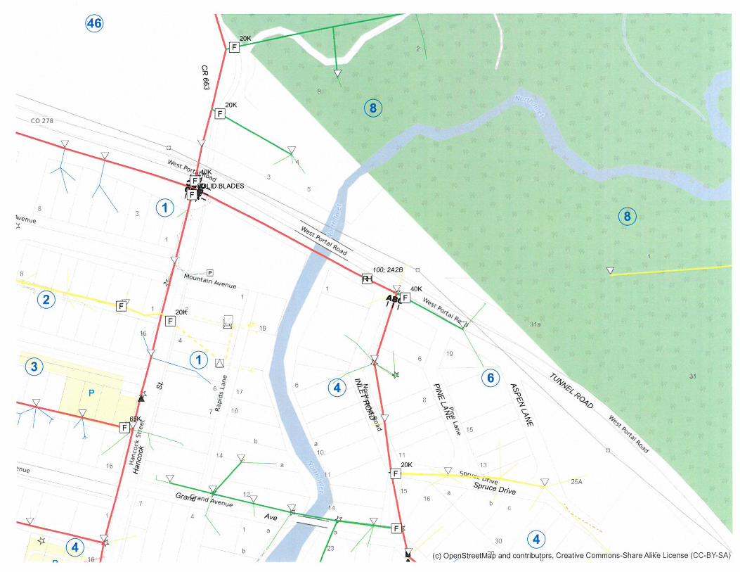
5. SCHEMATIC CONSTRUCTION SCHEDULE; To avoid a significant impact to the summer tourist season while using an off-site detour, we believe that the contractor would have to be given notice-to-proceed by about April 1. The following is an approximate schedule based on an April start date. Project Initiation and Mobilization April 1 to April 15 Traffic Closure April 16 Deck Demolition and Girder Modifications April 16 to April 30 Deck Construction and Concrete Curing May 1 to May 15 Sidewalk and Bridge Rail Construction May 16 to May 31 Guardrail Installation June 1 to June 7 Waterproofing Membrane and Paving June 8 to June 15 Open to Traffic June 16 Seeding and Punch List Completion June 16 to June 30 The Town should consider if impacts to traffic from Memorial Day to June 16 would cause an impact to local businesses that would be significant enough to justify the added cost of phased construction. A contingency should also be considered if construction is delayed such that Portal Road is not opened until July 1. We believe there would be at least a 20% increase in construction cost for phased construction. A fall schedule starting on August 1 is also possible, however, the contractor would likely need to come back the following spring to complete seeding or the Town would need to contract separately for the seeding item of work. Utility Consideration: There is an Xcel Energy gas line on the bridge. This gas line currently sits on top of one of the sidewalks. This gas line will need to be relocated prior to demolition of the existing bridge deck and this work can only be performed by Xcel personnel. This work can be left to the contractor to coordinate but there would be an advantage to the Town initiating the relocation prior to construction. Delays in initiating this relocation could negatively impact the project schedule. We also understand that there is an increase in the cost of the relocation if it is required prior to April. The Town should consider the advantages of initiating the relocation

Structure No. 0506.01 Portal Road Bridge BRO-M-560-003 Preliminary Design Report
Y:\Denver\151300S\00151386.00_Portal_Road\Office_Docs\Preliminary Design Report (working)\Portal Road Preliminary Design Report.docx
- 8 -
of this gas line. If the Town wants the contractor to coordinate this work, an extension of the schedule will likely need to be considered. Painting Consideration: Consideration should be given to removing the paint from the existing girders and repainting them. Since the existing girders were likely painted with lead-based paint, the removal process will be hampered by the need remove the paint under controlled conditions. The construction documents could potentially be structured to require painting the girders after the bridge deck is complete and the roadway is open to traffic. The contractor will probably, however, have a preference for paint removal and painting the girders will the roadway is still closed to traffic. There would likely be an increase in the cost of painting if the contractor is required to paint after the roadway is open to traffic. Schedule Impacts: If the contractor is required to coordinate the gas line relocation and is allowed to perform paint removal and repainting prior to opening the bridge to traffic, there will likely be about a four week increase in the construction duration. Assuming an off-site detour approach to the project and an April 1 notice-to-proceed, opening the bridge to traffic would be delayed until approximately July 16 and project close out until early August. 6. CONCLUSION: Deck replacement is the preferred method of bridge rehabilitation. A bridge cross section with only one sidewalk (compared with two existing sidewalks) has been selected to achieve an increase in the bridge roadway width. The increased roadway width will allow better traffic flow and safety on the bridge. In addition, the wider roadway should reduce the snowplow caused source of bridge deterioration. A steel curb plate will be used to improve the durability of the remaining sidewalk curb. Roadway drainage is being improved by revising the roadway profile to increase the slope near the ends of the bridge. Construction phase traffic control will be handled by an off-site detour. Adequate bridge rail and improved approach guardrail will be installed to safety on the bridge and approach roadway. Please let us know if you have any questions about the preliminary design report.

Structure No. 0506.01 Portal Road Bridge BRO-M-560-003 Preliminary Design Report
Y:\Denver\151300S\00151386.00_Portal_Road\Office_Docs\Preliminary Design Report (working)\Portal Road Preliminary Design Report.docx
- 9 -
Appendix A: Engineer’s Opinion of Probable Construction Cost
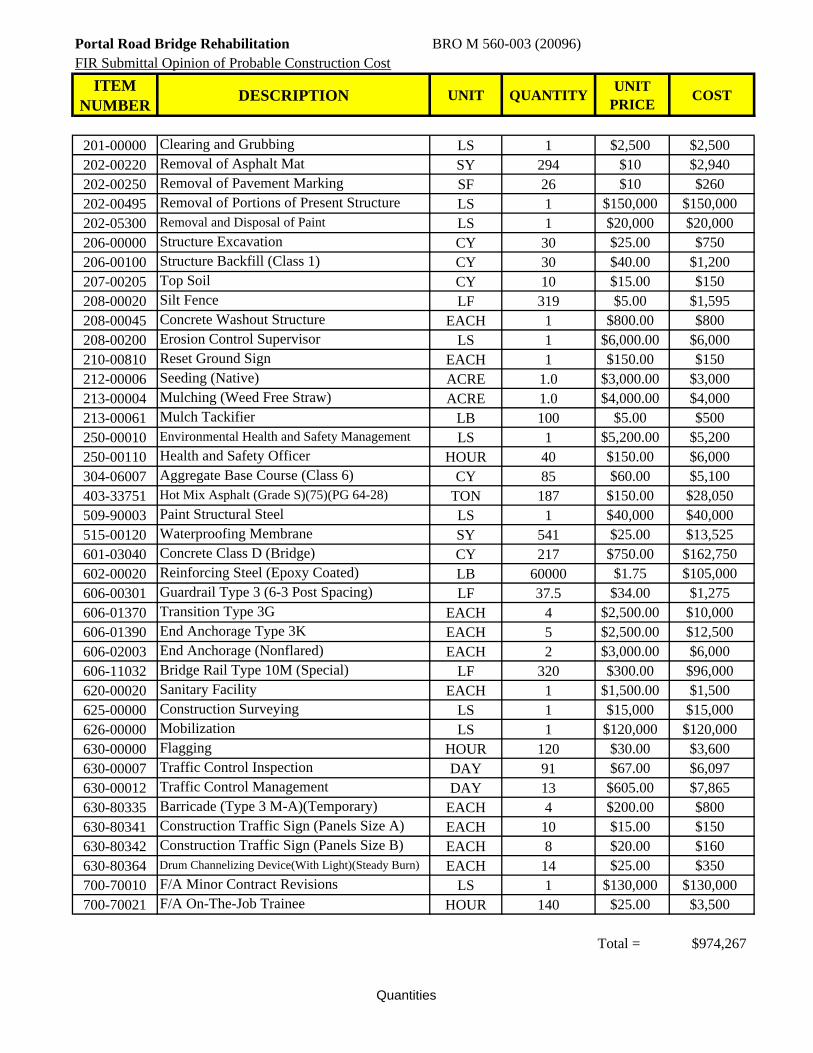
Portal Road Bridge Rehabilitation BRO M 560-003 (20096)FIR Submittal Opinion of Probable Construction Cost
ITEM NUMBER
DESCRIPTION UNIT QUANTITYUNIT
PRICECOST
201-00000 Clearing and Grubbing LS 1 $2,500 $2,500202-00220 Removal of Asphalt Mat SY 294 $10 $2,940202-00250 Removal of Pavement Marking SF 26 $10 $260202-00495 Removal of Portions of Present Structure LS 1 $150,000 $150,000202-05300 Removal and Disposal of Paint LS 1 $20,000 $20,000206-00000 Structure Excavation CY 30 $25.00 $750206-00100 Structure Backfill (Class 1) CY 30 $40.00 $1,200207-00205 Top Soil CY 10 $15.00 $150208-00020 Silt Fence LF 319 $5.00 $1,595208-00045 Concrete Washout Structure EACH 1 $800.00 $800208-00200 Erosion Control Supervisor LS 1 $6,000.00 $6,000210-00810 Reset Ground Sign EACH 1 $150.00 $150212-00006 Seeding (Native) ACRE 1.0 $3,000.00 $3,000213-00004 Mulching (Weed Free Straw) ACRE 1.0 $4,000.00 $4,000213-00061 Mulch Tackifier LB 100 $5.00 $500250-00010 Environmental Health and Safety Management LS 1 $5,200.00 $5,200250-00110 Health and Safety Officer HOUR 40 $150.00 $6,000304-06007 Aggregate Base Course (Class 6) CY 85 $60.00 $5,100403-33751 Hot Mix Asphalt (Grade S)(75)(PG 64-28) TON 187 $150.00 $28,050509-90003 Paint Structural Steel LS 1 $40,000 $40,000515-00120 Waterproofing Membrane SY 541 $25.00 $13,525601-03040 Concrete Class D (Bridge) CY 217 $750.00 $162,750602-00020 Reinforcing Steel (Epoxy Coated) LB 60000 $1.75 $105,000606-00301 Guardrail Type 3 (6-3 Post Spacing) LF 37.5 $34.00 $1,275606-01370 Transition Type 3G EACH 4 $2,500.00 $10,000606-01390 End Anchorage Type 3K EACH 5 $2,500.00 $12,500606-02003 End Anchorage (Nonflared) EACH 2 $3,000.00 $6,000606-11032 Bridge Rail Type 10M (Special) LF 320 $300.00 $96,000620-00020 Sanitary Facility EACH 1 $1,500.00 $1,500625-00000 Construction Surveying LS 1 $15,000 $15,000626-00000 Mobilization LS 1 $120,000 $120,000630-00000 Flagging HOUR 120 $30.00 $3,600630-00007 Traffic Control Inspection DAY 91 $67.00 $6,097630-00012 Traffic Control Management DAY 13 $605.00 $7,865630-80335 Barricade (Type 3 M-A)(Temporary) EACH 4 $200.00 $800630-80341 Construction Traffic Sign (Panels Size A) EACH 10 $15.00 $150630-80342 Construction Traffic Sign (Panels Size B) EACH 8 $20.00 $160630-80364 Drum Channelizing Device(With Light)(Steady Burn) EACH 14 $25.00 $350700-70010 F/A Minor Contract Revisions LS 1 $130,000 $130,000700-70021 F/A On-The-Job Trainee HOUR 140 $25.00 $3,500
Total = $974,267
Quantities
Structure No. 0506.01 Portal Road Bridge BRO-M-560-003 Preliminary Design Report
Y:\Denver\151300S\00151386.00_Portal_Road\Office_Docs\Preliminary Design Report (working)\Portal Road Preliminary Design Report.docx
- 10 -
Appendix B: Utility Coordination Documents

12071209
1211
107
355
300
220
200209213
207240
221
120
217
257
190
271210
E
2 W
43
147
27
20
504
10
51 3
B107
85
103 93
341
25 L
L
15
16
7 W
442
59?
LL
174
0
9
465
W2S
W1S2EW
W3S
S0W
N2W
N5E1NN
NW2NE3NWNW
S3E4SS
N13W1NN
S
E1N
E1N5NN
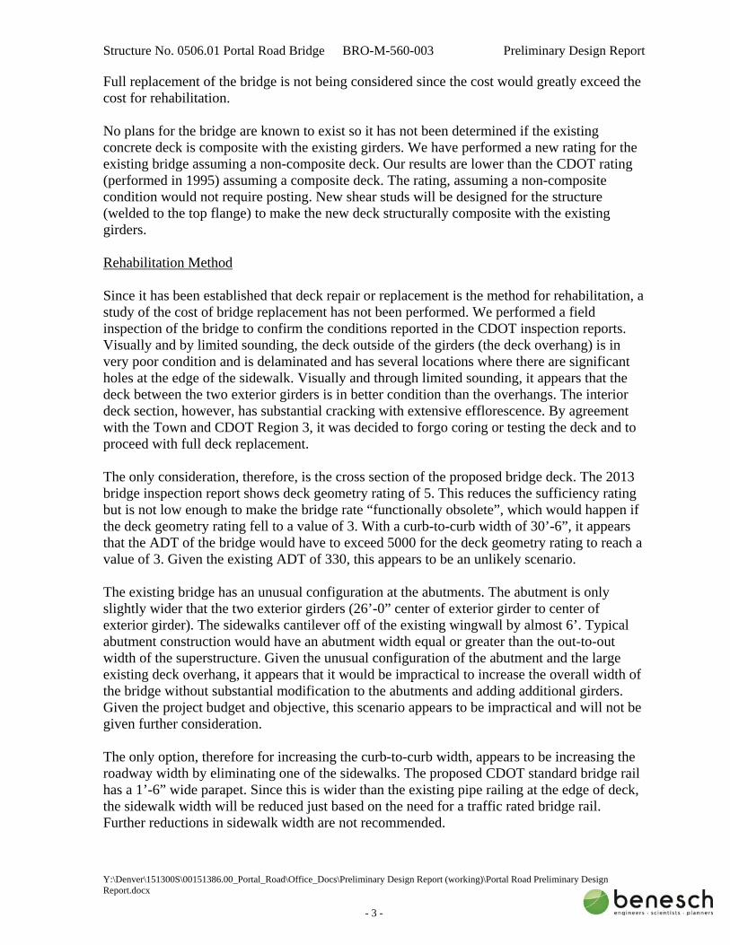
DISCLAIMER: THERE ARE NO REPRESENTATIONS OR WARRANTIES (EXPRESS OR IMPLIED) ABOUT THE ACCURACY OF THIS PRINT. THIS PRINT IS PROVIDED WITH NO CLAIM AS TO PRINT COMPLETENESS, TIMELINESS, ACCURACY OF CONTENT OR USEFULNESS. STATE LAW REQUIRES ANYONE DIGGING, GRADING OR EXCAVATING TO OBTAIN A PRIOR FIELD LOCATE OF ALL UTILITIES; THIS PRINT DOES NOT DISCHARGE THIS REQUIREMENT OR ANY OTHER REQUIREMENT. THE COMPANY AND ITS AFFILIATES ASSUME NO LEGAL RESPONSIBILITY OR LIABILITY FOR THE RECIPIENT'S USE (OR ANY OTHER PARTIES' USE) OF THE PRINT, INCLUDING THE RECIPIENTS INTENDED PURPOSE IN USING THE PRINT. NO COMPANY EMPLOYEE OR OTHER PARTY HAS BEEN AUTHORIZED TO PROVIDE THIS PRINT FOR PLANNING OR ESTIMATING PURPOSES; RELY ON THIS PRINT AT YOUR OWN RISK. BY ACCEPTING THIS PRINT, THE RECIPIENT & ANY OTHER PARTY RECEIVING A COPY OF THE PRINT ACKNOWLEDGES AND AGREES TO THIS DISCLAIMER. For All Field Locates Call 811
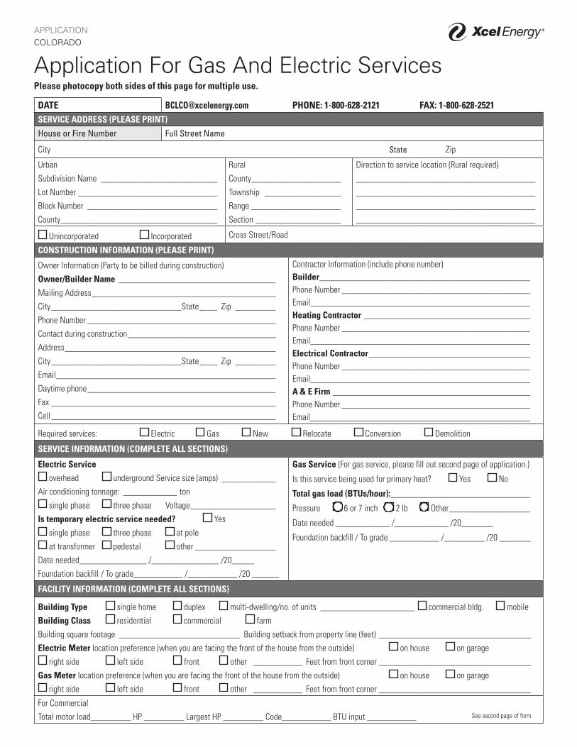
APPLICATION COLORADO
Application For Gas And Electric ServicesPlease photocopy both sides of this page for multiple use.
DATE [email protected] PHONE: 1-800-628-2121 FAX: 1-800-628-2521SERVICE ADDRESS (PLEASE PRINT)
House or Fire Number Full Street Name
City State Zip
Urban
Subdivision Name __________________________
Lot Number _______________________________
Block Number _____________________________
County ___________________________________
Rural
County ____________________
Township _________________
Range ____________________
Section ___________________
Direction to service location (Rural required)
________________________________________
________________________________________
________________________________________
________________________________________
Unincorporated Incorporated Cross Street/Road
CONSTRUCTION INFORMATION (PLEASE PRINT)
Owner Information (Party to be billed during construction)
Owner/Builder Name ___________________________________
Mailing Address _________________________________________
City _____________________________State ____ Zip _________
Phone Number __________________________________________
Contact during construction _________________________________
Address _______________________________________________
City _____________________________State ____ Zip _________
Email _________________________________________________
Daytime phone __________________________________________
Fax __________________________________________________
Cell __________________________________________________
Contractor Information (include phone number)Builder _______________________________________________Phone Number __________________________________________Email _________________________________________________Heating Contractor _____________________________________Phone Number __________________________________________Email _________________________________________________Electrical Contractor ____________________________________Phone Number __________________________________________Email _________________________________________________A & E Firm ____________________________________________Phone Number __________________________________________Email _________________________________________________
Required services: Electric Gas New Relocate Conversion Demolition
SERVICE INFORMATION (COMPLETE ALL SECTIONS)
Electric Service
overhead underground Service size (amps) ____________
Air conditioning tonnage: ____________ ton
single phase three phase Voltage ___________________
Is temporary electric service needed? Yes
single phase three phase at pole
at transformer pedestal other __________________
Date needed_______________ /_______________ /20_____
Foundation backfill / To grade___________ /___________ /20 ______
Gas Service (For gas service, please fill out second page of application.)
Is this service being used for primary heat? Yes No
Total gas load (BTUs/hour): _______________________________
Pressure 6 or 7 inch 2 lb Other __________________
Date needed ____________ /____________ /20_______
Foundation backfill / To grade ___________ /_________ /20 _______
FACILITY INFORMATION (COMPLETE ALL SECTIONS)
Building Type single home duplex multi-dwelling/no. of units _____________________ commercial bldg. mobile
Building Class residential commercial farm
Building square footage ___________________________ Building setback from property line (feet) __________________________________
Electric Meter location preference (when you are facing the front of the house from the outside) on house on garage
right side left side front other ___________ Feet from front corner __________________________________
Gas Meter location preference (when you are facing the front of the house from the outside) on house on garage
right side left side front other ___________ Feet from front corner __________________________________
For Commercial
Total motor load_________ HP _________ Largest HP _________ Code___________ BTU input ___________ See second page of form
xcelenergy.com | © 2014 Xcel Energy Inc. | Xcel Energy is a registered trademark of Xcel Energy Inc. | Public Service Company of Colorado, an Xcel Energy Company. | 14-03-307 03/2014
END USESEquipment type Gas (specify BTUs/hours input) Electric (specify kW) Other Fuel Type
Heating
Water heating
Cooking
Air conditioning
Clothes drying
Fireplace
Lighting (Commercial Only)
Heat source (check type) Forced air furnace Heat storage Underfloor/slab heat Baseboard
Meter Option (if applicable) Time of use Dual fuel Limited off-peak Saver’s Switch
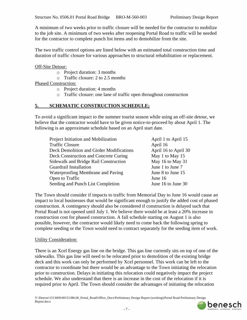
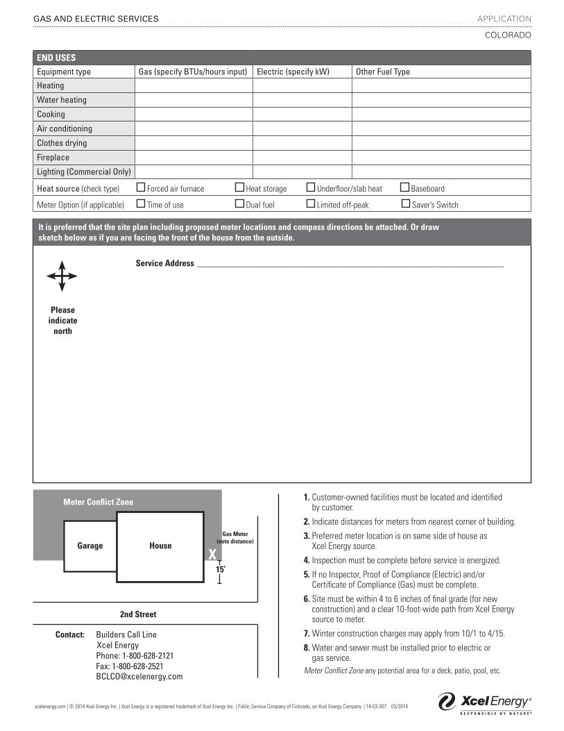
It is preferred that the site plan including proposed meter locations and compass directions be attached. Or drawsketch below as if you are facing the front of the house from the outside.
Service Address ______________________________________________________________________
Pleaseindicate
north
GAS AND ELECTRIC SERVICES APPLICATION
COLORADO
Meter Conflict Zone
XGarage House
2nd Street
Contact: Builders Call Line Xcel Energy Phone: 1-800-628-2121 Fax: 1-800-628-2521 [email protected]
1. Customer-owned facilities must be located and identified by customer.
2. Indicate distances for meters from nearest corner of building.
3. Preferred meter location is on same side of house as Xcel Energy source.
4. Inspection must be complete before service is energized.
5. If no Inspector, Proof of Compliance (Electric) and/or Certificate of Compliance (Gas) must be complete.
6. Site must be within 4 to 6 inches of final grade (for new construction) and a clear 10-foot-wide path from Xcel Energy source to meter.
7. Winter construction charges may apply from 10/1 to 4/15.
8. Water and sewer must be installed prior to electric or gas service.
Meter Conflict Zone any potential area for a deck, patio, pool, etc.
Gas Meter(note distance)
15’

1
Bechtold, Daniel
From: Mizyed, SamirSent: Monday, September 26, 2016 12:09 PMTo: Bechtold, DanielSubject: XCEL Energy Gas Line, Portal Road
Hi Dan, just a summary of what I what info I was able to get from Excel Energy. The Designer Loren Vawfer (970‐262‐4034) informed me that I would have to call the builders line in order to submit an application for temporary relocation of the gas line. However, due to the frost on the ground, they likely wouldn't be able to relocate the line until April 1st of next year. I called him again and asked if he could check to make sure of that date. I also called the builders line and they sent me a link to the online application we would need to fill out. I can forward that email if you need it. Samir Mizyed, EIT | Designer Alfred Benesch & Company | 7979 East Tufts Avenue, Suite 800, Denver, CO 80237
P 303-771-6868 / Direct: 720-473-7585 | C 303-476-0394 | E [email protected] | W www.benesch.com