Embed Size (px)
Citation preview

1 INTRODUCTION
The Vc Corridor is included in the TEN transport infrastructure network of South-Eastern Europe and passes in the direction Budapest (Hungary), via Osijek (Croatia), Sarajevo (B&H), to the Port of Ploèe (Croatia). The length of the Vc corridor route through Bosnia and Herzego-vina amounts to about 330 km, and runs in the direction North-South through the middle of the country, in most favorable natural conditions and through the valleys of the Bosna and Neretva rivers.
It is expected that the construction of this highway shall be a prime mover of economic ac-tivities enabling B&H to be included in the main European traffic streams and global European economic system.
Section Mostar North – South Border (LOT 4) of the Vc corridor is 67,3 km long and it is di-vided into five subsections, with different lengths, passing through various terrains. These sec-tions are: - Section 1: beginning of LOT 4 –Mostar North Interchange (9,800 km), - Section 2: Mostar North Interchange –Mostar South Interchange (16,450 km), - Section 3: Mostar South Interchange –Poèitelj Interchange (19,650 km), - Section 4: Poèitelj Interchange –Meðugorje (Zviroviæi) Interchange (12,100 km), and - Section 5: Meðugorje (Zviroviæi) Interchange – end of LOT 4 (9,329 km) General layout of the section Mostar North – South Border (LOT 4) of the Vc corridor with marked tunnels is presented on the following page.
Preliminary design for road tunnels on trans-European Vc corridor motorway, section Mostar North - South Border (Bosnia and Herzegovina)
I. Mustapiæ & D.Šariæ & M. Stankoviæ Civil Engineering Institute of Croatia, Zagreb, Croatia
ABSTRACT: This paper presents preliminary design preparation for road tunnels on the Trans-European Vc Corridor motorway, section Mostar North – South Border (LOT 4), which passes through Bosnia and Herzegovina. Total length of above mentioned section is 67,3 km, 14 km being in tunnels (which is about 21% of total length of the section). The challenges faced by the designers were obvious, especially due the fact that the Corridor route mostly passes through difficult, mountainous terrain. Due to this fact, 16 road tunnels of different lengths and cross-sections had to be designed, in a total length of tunnel tubes of approx. 29 kilometers. Therefore it can be concluded that the tunnels represent the key part of the section Mostar North – South Border (LOT 4) of the Trans-European Vc Corridor motorway which passes through Bosnia and Herzegovina. These tunnels were designed in accordance with the state-of-the-art guidelines, primarily the DIRECTIVE 2004/54/EC ON MINIMUM SAFETY REQUIREMENTS FOR TUNNELS IN THE TRANS-EUROPEAN ROAD NETWORK. As a result of different soil characteristics, different construction methods were proposed, primarily the NATM (New Aus-trian tunnel method) and the “CUT & COVER” method.

Figure 1: General layout of the section Mostar North – South Border (LOT 4) with marked tunnels
1.1 General information about the tunnels on LOT 4 of the Vc Corridor, passing through B&H Tunnels are designed with two tubes and the spacing between tunnel tube axes is min. 25 m. Anticipated tunnel execution technology is NATM (New Austrian Tunnel Method).

Tunnels shorter than 500 m are designed with an emergency lane along its total length, and tunnels longer than 500 m are designed with lay-bys at a maximum distance of 1000 m instead of an emergency lane.
The width of tunnel carriageway is selected on the basis of requirements for an equal width of traffic lanes as on the open part of the route.
Tunnels shorter than 500 m are not mechanically ventilated and the tunnels longer than 500 m are ventilated with longitudinal reversible ventilation.
On every lay-by, there is a transversal passage for vehicles. Transversal passages for evacua-tion are placed at maximum distance of 500 m.
In tunnels with larger longitudinal carriageway slopes, transversal pedestrian passages are placed at maximum distance of 250 m.
SOS recesses are spaced near the portals and at maximum distance of 150 m and are equipped with TPS and manual fire alarm with two fire apparatuses for initial extinguishing. Hydrant network is designed in tunnels longer than 500 m.
All the tunnels are equipped with lighting system. Tunnels longer than 2 km are equipped with video and audio system and tunnels longer than 1 km are equipped only with radio system.
2 CROSS-SECTIONS OF TUNNEL TUBES
2.1 Types of cross-sections used There are three types of tunnel cross sections on the objective section, depending on their
length, provided technology of execution, as well as on the number and width of traffic lanes on the open part of the route.
Two- and three-lane tunnels are designed, taking into consideration that on the part of the route where there is an additional lane for vehicles, three-lane tunnels are somewhat larger in profile in relation to the designed three-lane tunnel applied in cases of tunnels with emergency lane (shorter than 500 meters).
According to the above mentioned terms, most frequently used are the three-lane tunnels with an emergency lane. There are 7 tunnel like this (Komiæ, Vijenac, Osoje, Gorica, Kièin, Šunja Glava, Bijela Vlaka), total length of nearly 5 km, followed by two-lane tunnels, of which there are 5 (Orlov Kuk, Debelo Brdo, Oštri Rat, Samac, Kvanj), but their total length is ap-proximately nearly 20 km. After this, we have 4 three-lane tunnels with an additional lane (Rudine, Koèine 1, gallery Koèine 2, Rožni Kuci), total length of nearly 4 km. All the above mentioned tunnels are designed with two tunnel tubes except Koèine 2 which has a single car-riageway in a gallery and the other on an open route.
Depending on the chosen cross-section type, we have different clearance surface areas. Pro-file clearance is 59,13 m2 for two-lane tunnels, 83,90 m2 for three-lane tunnels with emergency lane and 94,30 m2 for three-lane tunnels with additional lane. Such cross-sections completely satisfy demands for profile clearance as defined by the “Law on basic requirements for public roads and their elements outside settlements regarding traffic safety”, as well as the require-ments for profile clearance defined by the Austrian RVS guidelines and TEM standards. More-over, the mentioned cross-section allows for the accommodation of all the necessary devices and equipment, and enables aeration by means of horizontal ventilation. The speed limit of 100 km/h must be provided , as required by the design.
Width of tunnel carriageway is selected on the basis of requirements that the same width of traffic lanes and marginal strips should be maintained as on the open part of the route. Total width is 8 m for two-lane tunnels, 10,75 m for three-lane tunnels with emergency lane, and 11,75 m for three-lane tunnels with additional lane. Inspection lanes are elevated from the traffic surface of the tunnel by 15 cm. Total width of inspection lanes is 90 cm, for two-lane tunnels and 100 cm for three-lane tunnels. Under the inspection walkways there are channels for instal-lation of the required tunnel facilities. The channel on the inner side is used for placing the hydrant network, while the channel on the outer side serves for supply and telecommunication installations. Power supply installation ducts should be executed with the cross fall of 2 % towards the edge where the channel discharge is located. The tunnel cross sec-tion is rotated following the cross fall of the carriageway.
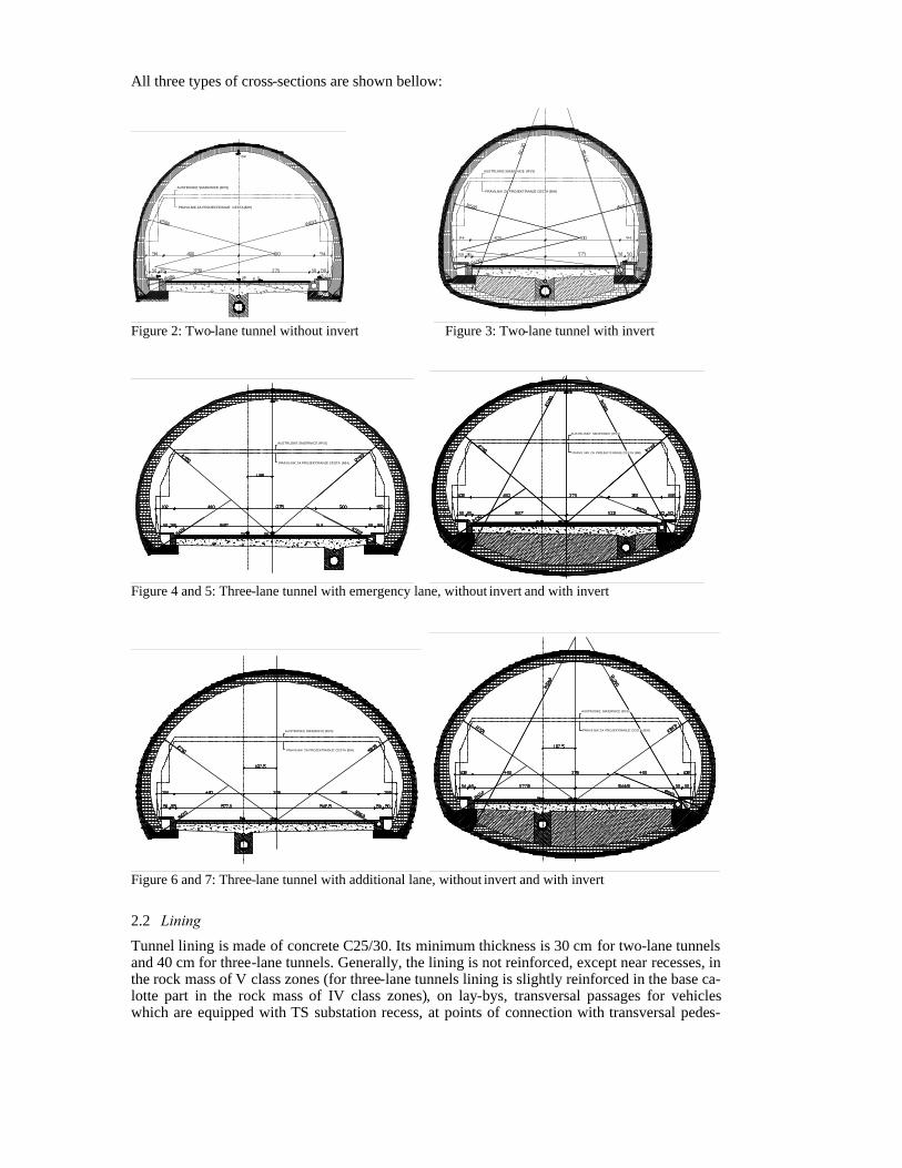
All three types of cross-sections are shown bellow:
AUSTRIJSKE SMJERNICE (RVS)
PRAVILNIK ZA PROJEKTIRANJE CESTA (BIH)
AUSTRIJSKE SMJERNICE (RVS)
PRAVILNIK ZA PROJEKTIRANJE CESTA (BIH)
Figure 2: Two-lane tunnel without invert Figure 3: Two-lane tunnel with invert
AUSTRIJSKE SMJERNICE (RVS)
PRAVILNIK ZA PROJEKTIRANJE CESTA (BIH)
AUSTRIJSKE SMJERNICE (RVS)
PRAVIL NIK ZA PROJEKTI RANJE CESTA (BIH)
Figure 4 and 5: Three-lane tunnel with emergency lane, without invert and with invert
A USTRIJSK E SMJERNICE (RVS)
PRAVILNIK ZA PROJEKTIRANJE CESTA (BIH)
AUSTRIJSKE SMJERNICE (RVS)
PRAVILNIK ZA PROJEKTIRANJE CESTA (BIH)
Figure 6 and 7: Three-lane tunnel with additional lane, without invert and with invert
2.2 Lining Tunnel lining is made of concrete C25/30. Its minimum thickness is 30 cm for two-lane tunnels and 40 cm for three-lane tunnels. Generally, the lining is not reinforced, except near recesses, in the rock mass of V class zones (for three-lane tunnels lining is slightly reinforced in the base ca-lotte part in the rock mass of IV class zones), on lay-bys, transversal passages for vehicles which are equipped with TS substation recess, at points of connection with transversal pedes-

trian passages and passages for emergency vehicles and in portal zones. Also, the foundation threshold is to be reinforced along the entire tunnel length.
Between the tunnel lining and primary tunnel support a permeability layer is provided by a PVC foil protected by geotextile. The PVC foil is provided with signaling layer, made in one piece, 2 mm thickness. The insulation is laid on the geotextile layer, minimum weight of 500 g. Tunnel insulation is provided along the entire length of the tunnel and on the entire calotte sur-face and tunnel flanks, and it shall be executed after the excavation and the execution of the primary tunnel security, and after the settling of possible displacements in the primary lining of the tunnel tube.
3 TUNNEL DRAINAGE
The tunnel drainage consists of a centrally laid sewage pipe, 500 mm diameter, while carriage-way drainage is done by means of a hollow curb system which collects water from the car-riageway surface.
Considering the characteristics of rock mass, the tunnel passes through a karts terrain, creat-ing a possibility of significant water inflow, which needs to be collected and directed by a spe-cial pipeline to the discharge at a suitable place within the tunnel (cave) or out of the tunnel into the terrain.
At the tunnel flanks, a RAUDRIL drainage pipe of 150 mm diameter is provided for collec-tion of hill water and its drainage into the central sewer. In order to allow access and inspection of the side drainage pipe, recesses are designed where drainage manholes shall be situated. Dis-charge from these manholes to the sewer manhole is executed by PVC pipes of 150 mm diame-ter. Distance between manholes amounts to approximately 50 meters.
Carriageway drainage in the tunnel refers to liquids deriving from liquid (inflammable) out-flow during a traffic incident and requires a carriageway drainage system which ensures the drainage of incident liquids, with a intake capacity of 200 l/s at carriageway length of 200 m. In order to meet the above mentioned conditions, hollow curb is provided with a continued hori-zontal opening of reinforced concrete C30/37 of 30 cm diameter. The hollow curb is manufac-tured as a precast element which is integrated onto the prepared base on the foundation thresh-old.
Siphon outlets are executed with a spillway dam in order to prevent spreading of fire in the sewer. The siphon outlet is executed of reinforced concrete C30/37. The liquid from the siphon outlet is taken by PVC pipes, 20 cm diameter, into the sewer manhole. The distance between siphon outlets is approximately 100 meters.
The main sewer system is made of impermeable PVC pipes of 500 mm diameter. The sewer in the two lane tunnel is located in the carriageway center, in three-lane tunnels with an addi-tional lane in the carriageway centerline and in three-lane tunnels with emergency lane, the sewer is situated in the emergency lane.
The carriageway liquids, water collected through side drainage system and water from the drainage of pavement structure sub-base layer are taken into the sewer through manholes.
Manholes are provided at mutual distance of approx. 50 m. Manholes are executed as mono-lithic constructions of reinforced concrete C25/30 or as precast, with precast reinforced plate and cast iron cover of 600 mm diameter, of 400 kN bearing capacity
4 TUNNEL VENTILATION
Tunnels are designed with longitudinal ventilation. Tunnels with a total length less than 500 m are ventilated naturally.
Tunnels from 500 m to approximately 800 m length are designed according to demand that ventilation system must be able to reach the air flow speed of min. 1,5 m/s.
Ventilation of tunnels longer than 800 m is designed according to the requirement that venti-lation system must be able to reach critical speed of 3 m/s.
Sensors for air flow velocity are designed, so that management of the ventilation system could function properly. Also there are CO concentration and rigid particles sensors. Minimum 2 pieces are required, also one CO sensor and one fire detection sensor in each fire zone.
5 FIRE ALARM SYSTEMS
Fire alarm systems are designed in tunnels longer than 500 m. Its main purpose is fast and reli-able fire detection.
Except the above mentioned it has to satisfy the following requirements: - Selective alarm activation - Communication with surveillance and management center - Initialization of actions regarding to initial fire extinguishing - Evacuation of people
At detection level, system is executed with use of two kinds of communicators. Sensor cable is placed through total length of main tunnel tubes and spot communicators are placed in SOS recesses, TS and UPS rooms.
6 ELECTRICAL INSTALLATIONS
Lighting is designed in all of the tunnels as well as in portal zones. The designed lighting system is as follows: adjustable, basic tunnel lighting and anti-panic
lighting. Following installations are connected on reserve power supply:
- recess lighting - ventilation measuring devices - safety tunnel lighting - anti-panic lighting - fluorescent SOS devices and SOS distribution facilities - variable traffic signalization - traffic signalization, lighting and remote guidance controllers and warning devices - fire alarm system - video system
Also, there is a low-voltage power supply unit for supplying and management of electro ven-tilation system.
7 PORTAL STRUCTURES
Generally, portal structures are designed as structures extracted from the tunnel tube. The de-signed length of the portal construction is 12 m.
Portal construction is provided from reinforced concrete C25/30. Lining thickness amounts to minimum 60 cm.
A drainage system must be made near the tunnel flanks, with pipes RAUDRIL DN 150 type, wit a discharge into the manholes at tunnel portals. A channel must be executed at the approach cutting face.
The portal construction waterproofing is provided in the part where portal construction is cut and covered with excavation material. Waterproofing is executed with PVC foil.
8 LAY-BYS AND TRANSVERSAL PASSAGES
8.1 Lay-bys Lay-bys are designed as surfaces 40 meters long and 3 meters wide. They are used for stopping broken-down vehicles, so they are equipped with SOS devices. Except that, in every lay-by, a surface for accommodation of UPS and hydrant is designed.

8.2 Transversal passages for vehicles Transversal passages for vehicles are used as an evacuation route in case of fire, and for redi-recting traffic in case that one tunnel tube is impassable or closed. They are located opposite to the lay-bys and are equipped with substations.
Transversal passages for vehicles are divided with fire walls. On every fire wall there is a slide door for vehicles with dimensions 4,5 m * 5 m and two glass doors for pedestrians with dimensions 100 * 220 cm. Doors and walls are fire resistant for 90 minutes.
Figure 8: Lay-bys and transversal passage for vehicles
8.3 Transversal passages for emergency vehicles Transversal passages for emergency vehicles are used for evacuation of people from one tube into another and for access of emergency vehicles at place of the incident. They are situated at distance of no more than 500 m.
Transversal passage for emergency vehicles has profile clearance of 3,6 m * 3,5 m. They are divided with fire wall. On every fire wall there is a slide door for emergency vehicles with di-mensions 3,6 m * 3,5 m and two glass doors for pedestrians with dimensions 100 * 220 cm. Doors and walls are fire resistant for 90 minutes.
Figure 9: Transversal passage for emergency vehicles Figure 10: Transversal passages for pedestrians

8.4 Transversal passages for pedestrians At sections with larger longitudinal slopes, transversal passages for pedestrians were designed. They are placed halfway between passage for emergency vehicles and passage for vehicles.
They allow evacuation of tunnel users from one tube into another. Designed profile clearance is 250 * 225 cm, and at every end of the passage there is a fireproof bulkhead with built-in round door for pedestrians, dimensions 100 * 220 cm, with fire-proof glass dimensions 40 * 100 cm. Doors and bulkheads are fire resistant for 60 minutes.
8.5 SOS recesses SOS recesses are situated at maximum distance of 150 m. They are equipped with TPS, manual fire alarm and with two fire apparatuses for initial extinguishing of fire.
SOS recesses have dimensions 240*225*130 cm. They are closed with fire-proof bulkhead. On bulkhead there are doors that have dimensions 210*70 cm, and they are glassed with glass dimensions 40 * 100 cm.
8.6 Hydrant recesses Hydrant recesses are designed with dimensions 240*225*100 cm, and they are situated at dis-tance of approximately 125 m. By the design, they are placed near every transversal passage and halfway between two transversal passages.
9 EXECUTION METHODS
Chosen method of execution is NATM (New Austrian Tunnel Method). CUT & COVER method is used at lower thickness of overburden.
9.1 Cut & cover method Following tunnels were designed to be executed using Cut & cover method: - right tube of tunnel Komiæ (0,457 km) - part of right tube of tunnel Rudine (app. 0,132 km) - part of right tube of tunnel Orlov kuk (app. 0,080 km) - gallery Koèine 2 (0,120 km)
After the first temporary cutting is excavated, slopes must be protected. After that it is neces-sary to execute channels on the flanks of a working cut.
Cut & cover tunnels are designed to be executed from reinforced concrete C25/30. Thickness of lining is minimum 60 cm. It is necessary to execute drainage down the flanks.
After the tunnel lining is concreted, in open cut, it is necessary to execute hydro isolation that has to be protected.
Backfilling is executed in layers with maximum thickness of 50 cm, and compacts with ap-propriate compacting utilities.
9.2 NATM (New Austrian Tunnel Method) New Austrian Tunnel Method is an excavation method which is very flexible regarding often changes of geological and geotechnical conditions. Following tunnels were designed to be exe-cuted using NATM: - left tube of tunnel Komiæ (0,500 km) - Tunnel Rudine (cca. 0,415 km) - Tunnel Orlov kuk (cca. 4,797 km) - Tunnel Gorica (0,804 km) - Tunnel Kvanj (5,355 km) - Tunnel Kièin (0,748 km)

- Tunnel Bijela Vlaka (0,988 km) - Tunnel Debelo brdo (2,096 km) - Tunnel Vijenac (0,217 km) - Tunnel Osoje (0,270 km) - Tunnel Oštri rat (5,648 km) - Tunnel Samac (1,267 km) - Tunnel Koèine 1 (0,753 km) - Tunnel Rožni kuci (2,404 km)
10 TUNNEL SUPPORT SETS
Designed support sets as well as recommendations of measures on excavation and stabilization of tunnel cuttings, were chosen based on experience acquired from previous designs in carbon-ated rocks. It will be shown for following rock mass class zones: - rock mass of II class zone - rock mass of III class zone - rock mass of IV class zone - rock mass of V class zone
10.1 Basic tunnel support set type II Support is used in basic rock mass of class II according to the geo-mechanical classification (RMR=61-80), and contains the following support elements:
- crown shotcrete of 5 cm thickness, systematic anchoring with adhesion bar anchors, corrugated steel Ø 25 mm, 3.0 m long, spaced at 2.5 m. - walls without support.
10.2 Basic tunnel support set type III Support is used in basic rock mass of the class III, according to the Geo-mechanical classifica-tion (RMR=41-60), and contains the following support elements:
- crown shotcrete of 10 cm thickness, steel welded mesh Q 131, systematic anchoring with adhesion bar anchors, corrugated steel Ø 25 mm, 3.0 m long, spaced at 2 m. - walls shotcrete 5 cm thick.
10.3 Basic tunnel support set type IV Support is used in basic rock mass of the class IV, according to the Geo-mechanical classifica-tion for RMR=21-40, and contains the following support elements:
- crown shotcrete of 15 cm thickness, steel welded mesh Q 131, systematic anchoring with adhesion bar anchors, corrugated steel Ø 25 mm, 3.0 m long, spaced at 1.7 m (if necessary with self-drilling injection anchors type IBO R25N Ø 25/14 mm). - walls shotcrete 10 cm thick steel welded mesh Q 131, systematic anchoring with adhesion bar anchors, corrugated steel Ø 25 mm, 3.0 m long,

spaced at 2.0 m (if necessary with self-drilling injection anchors type IBO R25N Ø 25/14 mm).
10.4 Basic tunnel support set type V Has been provided fro integration in the fault and fracture zone sin the V class rock mass (RMR<20), and it consists of the following support elements:
- crown shotcrete of 20 cm thickness, two steel welded meshes Q 221, systematic anchoring with self-drilling injection anchors type IBO R32N Ø 32/18.5 mm, 4.0 m long, spaced at 1.4 m, truss girders, Pantex 95/20/30 spaced at 1.0 m. - walls shotcrete of 20 cm thickness, two steel welded meshes Q 221, systematic anchoring with self-drilling injection anchors type IBO R32N Ø 32/18.5 mm, 5.0 m long, spaced at 1.4 m, truss girders, Pantex 95/20/30 spaced at 1.0 m. - invert shotcrete of 20 cm thickness, two steel welded meshes Q 221 Considering the fact that there is no initial stability of ground excavations in the class V rock
mass, the progress shall be made by fore poling of the steel ribs (corrugated steel Ø 25 mm, 4.0 m long) spaced at 30 cm, over the truss girders. Steel ribs need to be fore poled only in the zone of tunnel crown.
11 CONCLUSION
Complexity of section Mostar North – South Border (LOT 4) of the Vc corridor is visible from a fact that from total length of 67,3 km, as much as 21% (14 km) is in tunnels. Because of this we can say that tunnels are one of the key parts of the objective section from aspect of financ-ing, building, using and maintenance of the motorway.
Apart from given TEM standards, these tunnels were designed in accordance with the state-of-the-art guidelines, primarily the DIRECTIVE 2004/54/EC ON MINIMUM SAFETY RE-QUIREMENTS FOR TUNNELS IN THE TRANS-EUROPEAN ROAD NETWORK. Accord-ing to given directives, special attention was given to safety standards.
REFERENCES
1. “Directive 2004/54/EC on minimum safety requirements for tunnels in the Trans-European Road Network”, European Parliament and Council, Bruxelles, 2004.
2. Preliminary design corridor Vc motorway Mostar North - South border (LOT 4), designs of tunnels and structures, Civil Engineering Institute of Croatia , Zagreb, 2006.
3. RVS 9.281, RVS 9.282, “Strasse und Verkehr“ (FSV), Wien, 2002. 4. “Regulations on basic conditions to be met with by public roads and their elements outside
towns from the point of view of traffic safety”, Croatian Ministry of sea, transport and com-munication, Zagreb, 2001.