Embed Size (px)
Citation preview

Porsche Aircooled Piston and Cylinder Assembly Instruction Manual
Thank you for purchasing a MAHLE Motorsport Aircooled Piston and Cylinder kit.
Aircooled Piston and Cylinder Assembly Instructions:
MAHLE Motorsports North America has taken the extensive experience gained at the OE and motorsports levels to develop a series of performance and racing piston and cylinder kits. These kits were designed for high performance applications and are modern adaptations of the original or aftermarket kits; therefore there may be visual differences that are intentional and beneficial to the performance, durability and longevity of the components.
The pistons are machined from forgings with narrower and shorter skirts to reduce weight and friction. They are then dual coated, with Phosphate and MAHLE’s proprietary GRAFAL® skirt coating. The phosphate is a dry film lubricant designed to help protect the pin bores from galling and ring grooves from micro-welding. The GRAFAL® anti-friction skirt coating is designed to reduce drag, wear and noise.
The kits are supplied with modern ring sets made from stronger more durable materials that are dimensionally narrower and shorter to be more conformable providing more consistent contact with the cylinders resulting in increased sealing and oil control.
The cylinders included in Motorsports air-cooled kits are produced and machined to original equipment tolerances, designed to provide increased performance, durability and longevity. Some applications are available as either a slip-in or machine-in design. The slip-in cylinders are simply a larger internal bore replacement. The machine-in cylinders require the engine cases be machined to a larger bore diameter to accept their larger spigot diameter. The larger spigot diameter is preferable for extreme applications as with highly boosted turbo or competition use engines.
Unboxing: All components are individually packaged as means of protection from damage.
These kits require assembly and, as a performance application, several considerations should be made. Ensure the entire instruction sheet is read before beginning.
Inspection: Pin/Rod Clearance Proper pin to rod clearance should be insured prior to piston/rod assembly. Proper clearance depends on many factors and should be based on the rod manufacturers recommendations.
Piston to Head Clearance (Deck Clearance) Proper piston to head clearance is essential to compensate for both thermal expansion and inertial movement of the piston/rod assembly. The recommended clearance for a steel connecting rod is 0.040” and for an aluminum rod 0.060”
Compression Ratio The compression ratio shown in the application guide is calculated at 1mm (0.040”) deck clearance. The compression ratio of your specific application will vary depending on the deck clearance that the engine is built with.
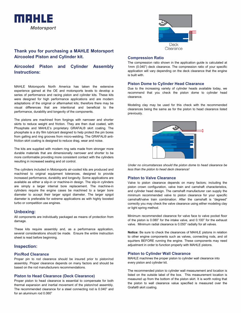
Piston Dome to Cylinder Head Clearance Due to the increasing variety of cylinder heads available today, we recommend that you check the piston dome to cylinder head clearance.
Modeling clay may be used for this check with the recommended clearances being the same as for the piston to head clearance listed previously.
Under no circumstances should the piston dome to head clearance be less than the piston to head deck clearance!
Piston to Valve Clearance Valve to piston clearance depends on many factors; including the piston crown configuration, valve train and camshaft characteristics, and cylinder head design. The camshaft manufacturer can supply the minimum recommended valve to piston clearance for your specific camshaft/valve train combination. After the camshaft is “degreed” correctly you may check the valve clearance using either modeling clay or light spring method.
Minimum recommended clearance for valve face to valve pocket floor of the piston is 0.080” for the intake valve, and 0.100” for the exhaust valve. Minimum radial clearance is 0.050” radially for all valves.
Notice: Be sure to check the clearances of MAHLE pistons in relation to other engine components such as valves, connecting rods, and oil squirters BEFORE running the engine. These components may need adjustment in order to function properly with MAHLE pistons.
Piston to Cylinder Wall Clearance MAHLE machines the proper piston to cylinder wall clearance into every piston and cylinder kit.
The recommended piston to cylinder wall measurement and location is listed on the outside label of the box. This measurement location is measured up from the bottom of the piston skirt. It is worth noting that the piston to wall clearance value specified is measured over the Grafal® skirt coating.

Piston Modification MAHLE Motorsports has designed these pistons to work “as delivered” in most applications, and we do not recommend modification of the pistons. Should modifications be necessary, there is no adverse effect if the phosphate surface coating is removed from the modified areas. NOTE: Care should be taken not to damage the GRAFAL® skirt coating.
Piston Ring Gaps The rings should be checked in the cylinder to ensure that the end gaps are sufficient. Recommendations and additional information is provided in the ring instructions located in the piston ring packaging. Should you require additional ring end gap, the rings should be gapped before installation on the piston.
Cleaning: Once you are satisfied the pistons have proper clearances, they should be thoroughly cleaned prior to final assembly.
Final Assembly: Care should be taken to keep the parts as clean as possible during final assembly. Any foreign material on the pistons or rings could lead to engine damage and/or less than peak performance.
Round Wire Clips The round wire clips can be easily installed by placing one end into the clip groove in the piston. Take a flat, blunt tool (such as a small screwdriver) and “walk” the clip into the groove. Make sure the clip is totally seated into the groove.
Warning: Under no circumstance should the clip be squeezed or compressed with pliers or other tools as this may result in deformation of the lock, resulting in failure to operate properly.
The following is the recommended procedure for proper seating: 1. After placing the first round wire lock in the groove, place pin in the piston and gently tap the piston pin against the previously installed wire lock using a wooden or plastic dowel. 2. Upon final assembly of the piston, pin, connecting rod, and remaining lock, repeat the seating process on the newly installed lock.
Top ring If there is a dot or a laser etching on one of the flats of the top ring, this marking is indicating top. Additionally, if there is a bevel on the ID of the top ring, the bevel should be facing up toward the top of the piston.
2nd Ring If there is a dot or a laser etching on one of the flats of the 2nd ring, this marking is indicating top. Additionally, if there is a bevel on the ID
of the 2nd ring, the bevel should be facing down toward the bottom of the piston.
Oil Ring - may be either 2 piece or 3 piece design:
2 Piece Instructions: Remove the coil spring from the oil ring and place the coil spring in the groove, noting the location of the coil spring joint. Install the oil ring in the ring groove; the oil ring gap must be assembled opposite (180 degrees) to coil spring joint.
3 Piece Instructions: Put the expander in the groove, ensure the ends are butted against each other. Expander ends must be positioned in line with the piston pin hole. Install the lower steel ring, the ring end gap must be approximately 45° left from the expander edges. Install the upper steel ring observing the same distance for the right side. After ring installation, check if oil ring set can move freely without binding. Important: expander ends must not overlap.
After following the above instructions, use a piston ring compressor to close rings in the piston before putting the assembly in the cylinder.
Piston Orientation In Engine For pistons that have an arrow laser etched on the crown, the pistons are installed so that the arrow points toward the flywheel.
For pistons with slanted dome and symmetric valve pockets, the pistons are installed so that the short end of the dome is located under the spark plug.
Final Thought: Prior to final engine assembly, the top, bottom, and face of each ring plus the cylinder bore should be lightly coated with clean, light-weight, conventional motor oil. DO NOT dip the entire piston as this may lead to improper seating of the rings.
Additional tech information and informative technical videos covering the above points are located on our website as well as the MAHLE Motorsport YouTube channel.
/MAHLEMotorsportNA/ @mahlemotorsport_NA www.youtube.com/user/mahlemotorsport www.mahlemotorsports.com

MAHLE Motorsport270 Rutledge Road Unit C Fletcher, NC 28732888-255-1942
www.mahlemotorsports.com
5/2
0