Embed Size (px)
Citation preview
Politecnico di Torino
Porto Institutional Repository
[Article] Characterization of Co-Cr-Mo alloys after a thermal treatment forhigh wear resistance
Original Citation:Balagna C.; Spriano S.; Faga M.G. (2012). Characterization of Co-Cr-Mo alloys after athermal treatment for high wear resistance. In: MATERIALS SCIENCE AND ENGINEERING. C,BIOMIMETIC MATERIALS, SENSORS AND SYSTEMS, vol. 32 n. 7, pp. 1868-1877. - ISSN0928-4931
Availability:This version is available at : http://porto.polito.it/2497188/ since: May 2012
Published version:DOI:10.1016/j.msec.2012.05.003
Terms of use:This article is made available under terms and conditions applicable to Open Access Policy Article("Public - All rights reserved") , as described at http://porto.polito.it/terms_and_conditions.html
Porto, the institutional repository of the Politecnico di Torino, is provided by the University Libraryand the IT-Services. The aim is to enable open access to all the world. Please share with us howthis access benefits you. Your story matters.
(Article begins on next page)
1
Characterization of Co-Cr-Mo alloys after a thermal treatment for high wear resistance
C.Balagnaa, *,S.Spriano
a , M.G. Faga
b
aInstitute of Materials Physics and Engineering, Department of Applied Science and Technology
Politecnico di Torino, Corso Duca degli Abruzzi 24,10129 Torino, Italy
bIstituto di Scienza e Tecnologia dei Materiali Ceramici,
Consiglio Nazionale delle Ricerche, Strada delle Cacce 73, 10135 Torino, Italy
*Corresponding author: Tel.: +39 011 5644668; Fax : +39 011 5644699;
E-mail address: [email protected]
This is the author post-print version of an article published on
Materials Science and Engineering: C, Vol. 32, n. 7, pp. 1868-
1877, 2012 (ISSN 0928-4931).
The final publication is available at
http://dx.doi.org/10.1016/j.msec.2012.05.003
This version does not contain journal formatting and may contain
minor changes with respect to the published edition.
The present version is accessible on PORTO, the Open Access
Repository of the Politecnico of Torino, in compliance with the
publisher’s copyright policy.
Copyright owner: Elsevier.
2
Abstract
The cobalt-chromium-molybdenum alloys are characterized by a high resistance to wear and
corrosion, as well as good mechanical properties, allowing their use in the substitution of hip and
knee joints.
Five alloys were used as substrates for a coating deposition by a thermal treatment in molten
salts, as reported elsewhere, in order to form a tantalum rich coating on the sample surface, able to
improve the biocompatibility and wear resistance of the materials. However, the temperature
(970°C), reached during this process, is considered critical for the phase transformation of the Co-
based alloys.
The aim of this work is the evaluation of the temperature effects on the structure,
microstructure, mechanical and tribological properties of the considered substrates, after the
removal of the coating by polishing. The substrates are characterized through X-ray diffraction
(XRD), scanning electron microscopy with energy dispersion spectrometry (SEM-EDS) and
profilometry. The mechanical behaviour is evaluated by the macro- and micro-hardness and
bending tests, whereas the tribological properties are analyzed through a ball on disc test. A
comparison between the as-received alloys and thermal treated substrates is reported. The
biocompatibility feature is not reported in this work.
The substrate crystalline structure changed during the heat treatment, inducing the formation
of the hexagonal cobalt phase and the decrement of the cubic one. This crystallographic
modification does not seem to influence the tribological behaviour of the substrates. On the
contrary, it affects the strength and ductility of the substrates.
Keyword: CoCrMo alloys, Heat treatment, Microstructure, Wear resistance, Arthroprosthesis
3
1. Introduction
The cobalt-chromium-molybdenum (CoCrMo) alloys can be used in the artificial replacements
of human hip and knee joints because of their good wear and corrosion resistance, as well as their
mechanical strength [1, 2]. The CoCrMo component of a prosthesis usually articulates on the same
alloy, on ultra high molecular weight polyethylene (UHMWPE) or on alumina, forming a metal on
metal (MoM), metal on polyethylene (MoP) or metal on ceramic (MoC) joint, respectively [3,4].
The knee joints, instead, are typically substituted with a MoP system [3].
The wear and corrosion of the bearing surfaces remain the principal causes of the early failure
of the implants, despite of the wide use of these materials and the improvements in the technique
and design of the implants, as well as in the surgical methods [4, 5]. The UHMWPE element is the
most critical in the wear feature because of the formation of debris, contributing to osteolysis [5-7].
Alternatively, the MoM and MoC couplings are considered suitable for younger and more active
patients because the wear of articulating surfaces is significantly reduced [8, 9]. However, the
CoCrMo alloys can be affected by the synergic action of both corrosive human body fluids and
friction [5, 10, 11]. In fact, metallic ions and particles are formed in a smaller size, but in a higher
number than the polyethylene debris [12-15]. Wear debris and ions could remain in the implant site
or be disseminated into the other organs and lymph nodes [16, 17], increasing the risk of
hypersensitivity or inducing a cascade of inflammatory events [7, 12, 18-21].
The tribological and mechanical properties of the Co-based alloys strongly depend on their
microstructure [22-24]. In the CoCrMo alloys, the face-centered cubic (FCC) and the hexagonal
closed packed (HCP) crystalline structures co-exist. Typically, the FCC phase is predominant at
room temperature, but the FCC→HCP transformation could be isothermally or strain- induced [23,
25, 26]. The other main feature of the Co-based alloys is the presence of carbon forming carbides
whose distribution and size is influenced by the manufacturing process [27, 28]. The main factors
that affect the wear resistance of CoCrMo alloys are the carbon amount, the homogeneity of the
4
carbides distribution and the presence of the HCP crystal structure [10, 13, 29]. However, some
contrasting studies are reported in literature on this last topic. It was verified that a tribological
system with an almost fully complete HCP structure on both the sliding components exhibits a
lower wear loss comparing to the FCC structure [24]. On the contrary, Varano and co-workers [22]
stated that the alloys with a higher amount of the FCC phase, stabilized by the carbon content,
which inhibits the martensitic transformation, exhibit lower wear, because the HCP crystalline
structure is more brittle and detrimental to wear. The carbides influence the wear by means the
hardness and the good coherency with the surrounding matrix, acting as a protective barrier against
the matrix delamination [22]. However, the high hardness of the carbides could cause abrasive wear
damage, when they are pulled-out and fractured from the matrix, decreasing the resistance to the
surface fatigue [23].
This work is focused on the influence evaluation of a thermal treatment in molten salts on the
mechanical and wear properties of several implant CoCrMo alloys, different in carbon content and
manufacturing processes. The thermal treatment in molten salts was performed at a temperature
(970°C) recognized as critical for the CoCrMo alloys, promoting the FCC→HCP martensitic
transformation [26, 41, 42]. This temperature was set because it allows the formation of a peculiar
coating on the alloy surface, as reported in the previous works of the authors [30-33]. The coating
was composed of a multilayer structure of tantalum carbides, and it is able to improve the
biocompatibility as well as the wear and corrosion resistance of the alloys. The well-known
biocompatible behaviour [34-37], excellent mechanical and tribological properties, as well as
corrosion resistance [38-40] of tantalum (Ta) and its compounds are shown on the coating. In
addition, it was observed by the authors that the mechanism of coating formation was the diffusion
of the tantalum from the salts to the alloy surface and the reaction of the tantalum with the carbon
contained in the Co-based substrate. It must be underlined that the substrate below the coating can
be affected by the employed temperature and the chemical surface reaction occurred during the
coating formation.
5
The aim of this work is to investigate if the different CoCrMo substrates are affected by any
micro-structural or mechanical changes. The carbides, present in the substrate, could be subjected to
a modification in the dimension, quantity and distribution, during the thermal treatment. The treated
alloys were evaluated after the complete removal of the coating and a comparison with the as-
received materials is reported in the paper. The metal ions release relative to the as-received alloys
and the coated samples was controlled in a previous work [30].
2. Materials and Methods
2.1 The substrates
Five CoCrMo alloys, different in the composition, carbon content and manufacturing process,
were considered. Three of them were characterized by a high carbon content (HC) and they were
produced by wrought processing (W), powder metallurgy (PM) or casting (C). The other two
contained a low carbon amount (LC) and they were manufactured by means of a wrought
processing or casting. All the alloys were supplied by Smith & Nephew Inc. in a disk-shape, with a
diameter of 30 mm and thickness of 3 mm, with a mirror polished surface. The carbon content was
evaluated by optical spectrometry (Spectro - Spectrolab 5) while the other alloying elements were
quantified through energy dispersion spectrometry (SEM-FEI, Quanta Inspect 200, EDS - EDAX
PV 9900), at a voltage of 15kV.
The as-received CoCrMo alloys were thermal treated in a mixture of Ta-rich salts using a
patented method [33], well described in previous works [30-32]. The thermal process was carried
out at 970°C for 45 minutes, in a tubular furnace, under a controlled Ar atmosphere. The sample
was completely dipped into the salts mixture, composed predominantly of K2TaF7 and 2wt.% of Ta,
during the whole treatment. A Ta-based coating was formed on the sample surface and then it was
completely removed by a careful polishing procedure with SiC papers from 600 to 4000 grit, until
obtaining a mirror-polished surface, in order to analyse the substrates. The treated substrates, so
obtained, will be named by adding the employed isothermal temperature and the suffix “sub” to the
6
name of alloy (such as HC-C970sub). The weight loss and thickness of the removed material layer,
with polishing, were measured about 2-3 g and 0.45-0.49 mm, respectively. The LC-C970sub
sample was an exception, because of the lower thickness of its coating (the removed material was
1.2 g and 0.08 mm).
2.2 Sample characterization
The roughness of all the samples was measured by means of a contact profilometer (Tencor P-
11), acquiring three typical parameters, the arithmetical mean roughness (Ra), root mean square
value (Rq) and ten-point mean roughness Rz. Three measurements were performed for each sample
in order to obtain statistical data.
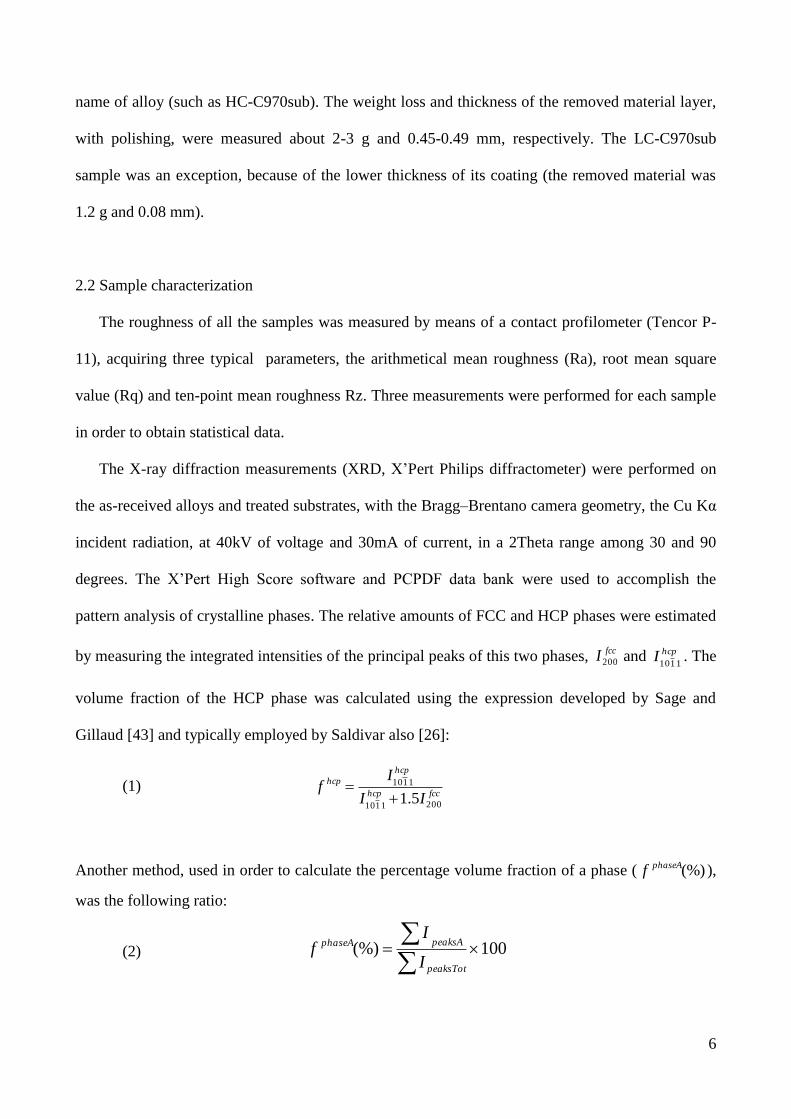
The X-ray diffraction measurements (XRD, X’Pert Philips diffractometer) were performed on
the as-received alloys and treated substrates, with the Bragg–Brentano camera geometry, the Cu Kα
incident radiation, at 40kV of voltage and 30mA of current, in a 2Theta range among 30 and 90
degrees. The X’Pert High Score software and PCPDF data bank were used to accomplish the
pattern analysis of crystalline phases. The relative amounts of FCC and HCP phases were estimated
by measuring the integrated intensities of the principal peaks of this two phases, fccI200 and hcpI
1110. The
volume fraction of the HCP phase was calculated using the expression developed by Sage and
Gillaud [43] and typically employed by Saldivar also [26]:
(1) fcchcp
hcp
hcp
II
If
2001110
1110
5.1
Another method, used in order to calculate the percentage volume fraction of a phase ( (%)phaseAf ),
was the following ratio:
(2) 100(%)
peaksTot
peaksAphaseA
I
If

7
where A is the considered phase, peaksAI is the sum of the intensities of all the peaks belonged to
the considered phase, peaksTotI is the sum of the intensities of all the peaks in the diffractogram.
A further investigation, for determining the phase amount and the crystal size, was performed by
using a program of Material Analysis Using Diffraction, called MAUD and developed at the
University of Trento. It is a general diffraction/reflectivity analysis program mainly based on the
Rietveld method.
The microstructure of the as-received alloys and treated substrates was analyzed. First, the
metallic carbides were observed by means of a scanning electron microscopy and energy dispersion
spectrometry (SEM-EDS, Philips 525M) at the voltage of 15 kV and by an optical microscope.
Afterwards, an etching procedure was performed, dipping all the samples for 5-10 seconds in an
acid solution of HCl and H2O2 (20:1) [44]. The optical microscope was used for the observation of
the grains.
The disk hardness was estimated by means of micro- and macro-indentation using a Vickers
indenter in both cases (Leitz Microvickers Penetrator and Dia Testor 2 RC- Wolpert). The applied
loads were 100g and 500 g for micro-indentation test and 40 kg for macro-indentation. Five
measurements for each samples were performed in order to obtain statistical data. The mechanical
resistance of the as-received alloys and the treated substrates was determined by means of a 3-point
bending test (MTS QTest/10). The samples were cut from the disks, obtaining rectangular cross-
sectioned bars with dimensions in accordance to ISO 3327-1982 standard [45]. The maximum
applied load was equal to 10 kN, reached with a load rate of 1 mm/min. The transverse rupture
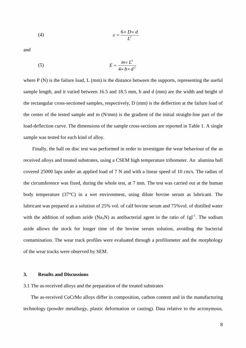
strength σ (MPa), the maximum bending deformation ε and the flexural elastic modulus E (GPa)
were calculated trough :
(3) 22
3
db
LP
8
(4) 2
6
L
dD
and
(5) 2
3
4 db
LmE
where P (N) is the failure load, L (mm) is the distance between the supports, representing the useful
sample length, and it varied between 16.5 and 18.5 mm, b and d (mm) are the width and height of
the rectangular cross-sectioned samples, respectively, D (mm) is the deflection at the failure load of
the center of the tested sample and m (N/mm) is the gradient of the initial straight-line part of the
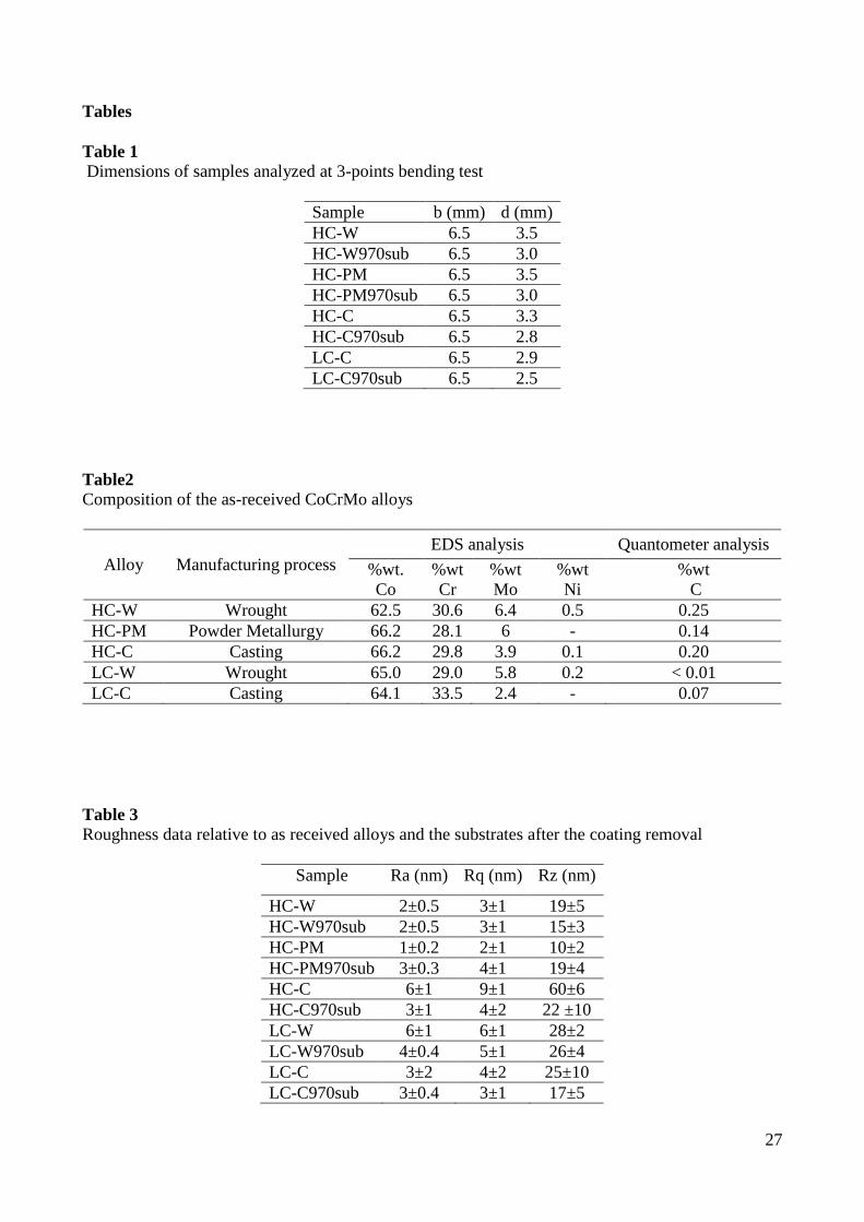
load-deflection curve. The dimensions of the sample cross-sections are reported in Table 1. A single
sample was tested for each kind of alloy.
Finally, the ball on disc test was performed in order to investigate the wear behaviour of the as
received alloys and treated substrates, using a CSEM high temperature tribometer. An alumina ball
covered 25000 laps under an applied load of 7 N and with a linear speed of 10 cm/s. The radius of
the circumference was fixed, during the whole test, at 7 mm. The test was carried out at the human
body temperature (37°C) in a wet environment, using dilute bovine serum as lubricant. The
lubricant was prepared as a solution of 25% vol. of calf bovine serum and 75%vol. of distilled water
with the addition of sodium azide (Na3N) as antibacterial agent in the ratio of 1gl-1
. The sodium
azide allows the stock for longer time of the bovine serum solution, avoiding the bacterial
contamination. The wear track profiles were evaluated through a profilometer and the morphology
of the wear tracks were observed by SEM.
3. Results and Discussions
3.1 The as-received alloys and the preparation of the treated substrates
The as-received CoCrMo alloys differ in composition, carbon content and in the manufacturing
technology (powder metallurgy, plastic deformation or casting). Data relative to the acronymous,

9
manufacturing technique and composition of the as-received materials are summarized in Table 2.
The carbon present in the HC alloys exceeds 0.1 wt.%, while the content in the LC samples is 0.07
wt.% in the casting alloy and less than 0.01 wt.% in the wrought alloy. The alloying elements are
similar in composition in all the materials, except for nickel that was only detected in a very low
quantity in the HC-W, HC-C and LC-W alloys. The carbon amount of the different alloys mainly
influences the formation and precipitation of carbides in the matrix [27], whereas the manufacturing
procedure typically affects the distribution and shape of the carbides [22].
The alloys were used as substrates in a thermal treatment in molten salts, performed at 970°C
for 45 min, in order to induce the formation of a tantalum-rich coating on the alloy surface, able to
improve the mechanical, wear and biocompatible behavior. The authors observed, in previous
works [31, 32], that the process under these precise conditions formed a peculiar coating, composed
of a multilayer structure of tantalum carbides. However, two relevant aspects arose concerning the
CoCrMo substrates. First of all, the treatment was performed at a temperature known as critical for
the martensitic transformation of the cobalt crystalline structure. Secondly, the mechanism of the
coating formation is diffusion-type and the tantalum, belonged to the salts, reacts with the carbon of
the CoCrMo substrate, to form the tantalum carbides phase, present in the coating. These features
could induce some changes also into the structure, microstructure and correlative properties of the
substrates.
The coated samples were polished in order to completely remove the coating and well-polished
surfaces were obtained. They have a roughness comparable to the as-received samples, according to
the standard for the prostheses [46] (Table 3).
3.2 The crystalline structure and microstructure
Fig. 1 shows the SEM images relative to the as-received alloys (on the left) and the substrates
(on the right), reporting also the EDS analysis on several areas. Both the HC-W (Fig.1a) and HC-
PM (Fig.1c) alloys show homogeneously distributed carbides inside the matrix. The samples,

10
obtained by powder metallurgy, contain, as usually, finer carbides than the wrought ones,
maintaining their dimension in the range of few micrometers. In the case of the cast alloys (Fig.1 e
and f, respectively), the carbides shape, dimension and distribution completely differ from the other
two alloy types. In fact, the carbides are less in number and they appear as agglomerates and blocks
into the matrix. Two kinds of carbides are noticed. The EDS analysis, reported in Fig. 1, suggests
that the light grey-white carbides contain a large amount of Mo (l), whereas the black-dark grey
carbides mainly contain Cr (i). In the cast alloys, the Mo carbides are larger (higher than 5 µm) and
with an irregular shape. On the contrary, the Cr carbides are smaller, presenting a circular and
regular shape. The carbides precipitated in the LC-C alloy are similar in distribution to the HC-C
sample, but fewer and larger. No photos about the LC-W alloy are reported because no carbides
were detected in this sample by SEM-EDS. The thermal treatment, performed in molten salts at
970°C, did not change the dimension, shape and distribution of the carbides, as it can be observed
by the comparison among the alloys before and after the process (Fig.3 b, d, f, h).
These results are congruent with those reported in literature [25, 28]. In fact, it is well known that
the carbide dissolution may happen only for a solution treatment performed at a temperature above
1150°C. It can be concluded that the tantalum carbides which formed the coating did not affect the
Mo and Cr carbides of the substrate.
Fig. 2 and 3 reported the XRD diffractograms with a comparison before and after the thermal
treatment for each alloy. It can be seen that the temperature reached in the thermal process, induced
a martensitic transfomation of FCC phase into HCP phase, confirming the studies conducted by
Saldivar – Garcia and co workers. It is reported that FCC phase easily transforms into HCP phase
during a thermal treatment of ageing at temperatures between 800-950°C [24-26, 41, 42]. The
CoCrMo alloys are typically characterized by the presence of two cobalt crystalline structures, the
cubic (FCC Co, PCPDF reference code 01-089-4307) and hexagonal (HCP Co, PCPDF reference
code 01-089-4308). As it could be observed, the three peaks of the FCC Co are noticed for all the
as-received alloys even if the LC-C alloys (Fig.3 b) presents a weak peak of FCC around 44°. In

11
addition, the relative intensity of the FCC peaks, in the cast alloys (Fig. 2c and 3b), is different with
respect to the other substrates, due to a preferential orientation caused by the manufacturing
process. An increment in the HCP amount is verified after the thermal treatment in all the
diffractrograms, confirming the data from literature. In fact, the HC-W970sub (Fig. 2a) and the LC-
W970sub (Fig.3a) samples show not only higher intensity of the two peaks at 41° and 47°, already
detected in the untreated alloys, but also the appearance of two other peaks around 62° and 84°
which were absent before the treatment. The thermal treatment induced a further re-distribution
between FCC peaks in the cast materials (HC-C970sub, LC-C970sub) where a preferential
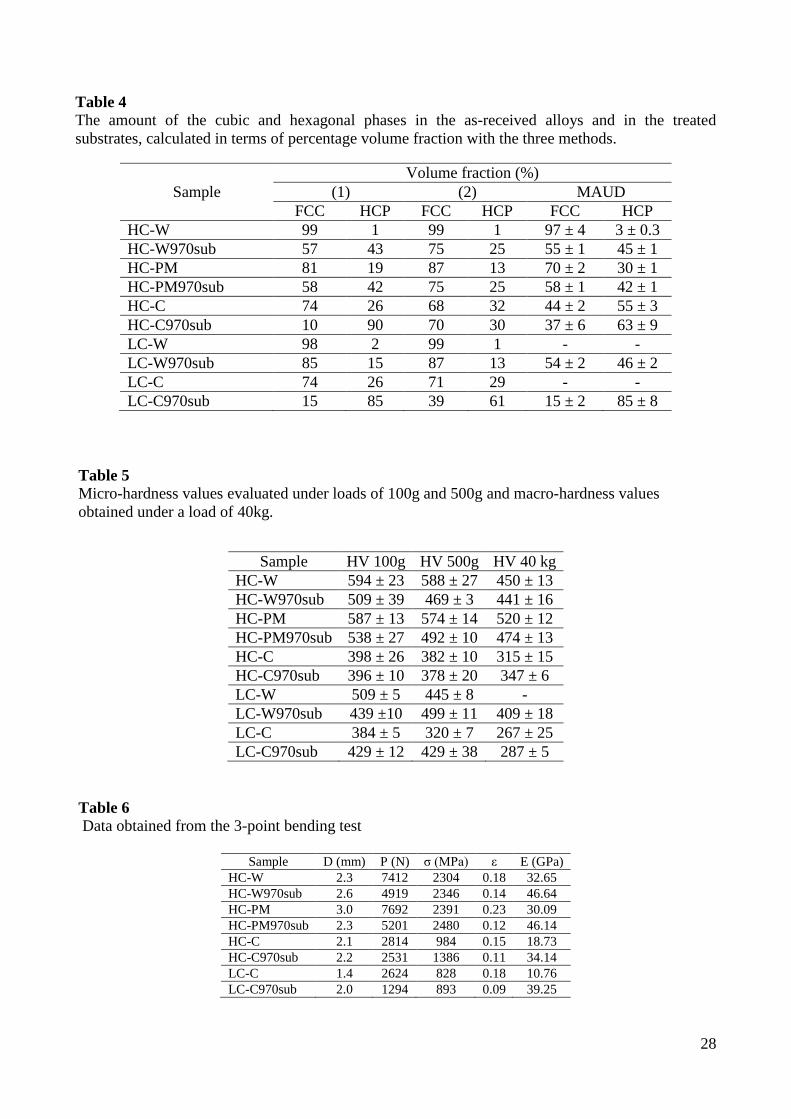
orientation is observed. Table 4 summarizes the volume fraction of the amount of the HCP and FCC
crystalline structures inside the alloys, estimated through (1), (2) and MAUD program. The data
obtained for the as-received wrought and powder metallurgy alloys are very similar comparing all
the methods of calculations. However, the values concerning the cast materials and all the treated
substrates are different and some contrasting results are obtained, comparing the different analyses.
Estimations from both the Sage and Guillaud’s formula and Rietveld-MAUD method has to be
considered not significant and precise for these samples. The preferential orientation of both the
FCC and HCP phases in the cast materials made invalid the measurements performed by these two
methods, which consider only the HCP peak with 100% of relative intensity in the PCPDF pattern
and the FCC peak with 40% of relative intensity in the PCPDF pattern. On the other hand, the
formula (2) considers all the peaks in the diffractogram so it is less sensitive to preferential
orientations. In conclusion, the high carbon alloys approached to a similar percentage volume
fraction of the HCP phase, after the thermal treatment, while a larger disparity was noticed in the
low carbon samples, in particular in the LC-C alloy where the HCP phase was significantly more
increased.
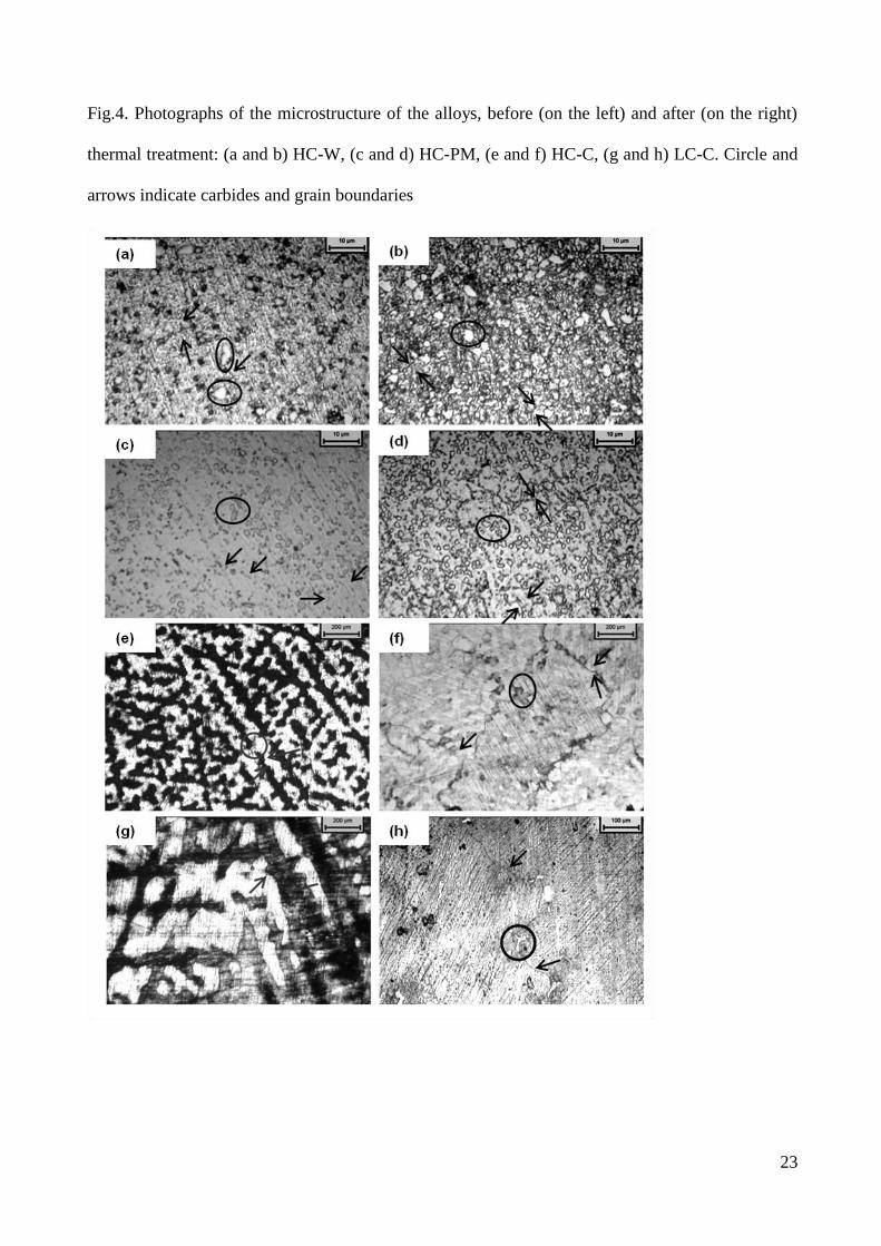
Fig. 4 reports some optical images of the microstructures relative to the as-received alloys and
treated substrates, after etching. The arrows and the circles indicated some grain boundaries and
carbides, respectively. The manufacturing technique deeply influences the alloy microstructure. In

12
fact, the HC-W alloy (Fig.4a) consists of a fine structure with an average grain size around 10 µm
and with a relevant presence of carbides. The grains in the HC-PM sample (Fig.4c) are larger than
in the wrought alloy, reaching dimensions between 10 and 20 µm, but with a finer carbides
distribution at the grain boundaries. Finally, the cast alloys (Fig.4e and g) show a similar coarse
microstructure with very large grains (above 100 µm for the HC-C alloy and above 200 µm for the
LC-C alloy) and a significant amount of the dark HCP phase, nucleated at the grain boundaries. The
thermal treatment, performed at 970°C for 45 min, relevantly affected the sample microstructure
and grain dimensions and the progressive formation of the HCP structure occurred in all the
analyzed samples. The HCP phase is morphologically identified as a dark phase inside the light
grey FCC matrix. The thermal treatment seems to refine the grain size in the HC-Wsub970 (Fig.4b)
and HC-PMsub970 (Fig.4d), in contrast with the cast alloys where the grains result further
increased. In particular, the grains in the LC-C970sub (Fig.4h) result very large and only part of a
grain boundary (indicated by arrows) but not the complete grain can be observed at this
magnification in the reported figure. In addition, some white carbides are noticed (dark circle).
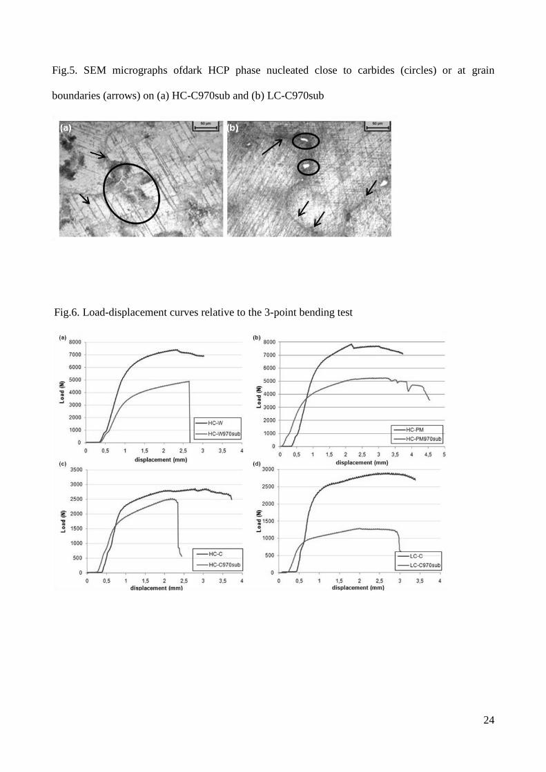
Considering the cast alloys, the thermal treatment was able to promote the development of the
elongated HCP plates along the FCC dendrites or a high density of short plates close to the carbides
[24, 41]. The formation of the HCP phase as very fine interdendritic striations starts to nucleate
close to the precipitated carbides in the HC-C970 alloy (Fig.5a) or only at the grain boundaries in
the LC-C970 alloy (Fig.5b) [41].
3.3 Mechanical properties
Table 5 reports the values of the micro- and macro-hardness obtained from the tests with a
Vickers indentator under different loads. The thermal treatment, generally, decreased the hardness
of the substrates, especially those containing a high carbon content. On the contrary, the LC-
C970sub sample shows a slight increment.
13
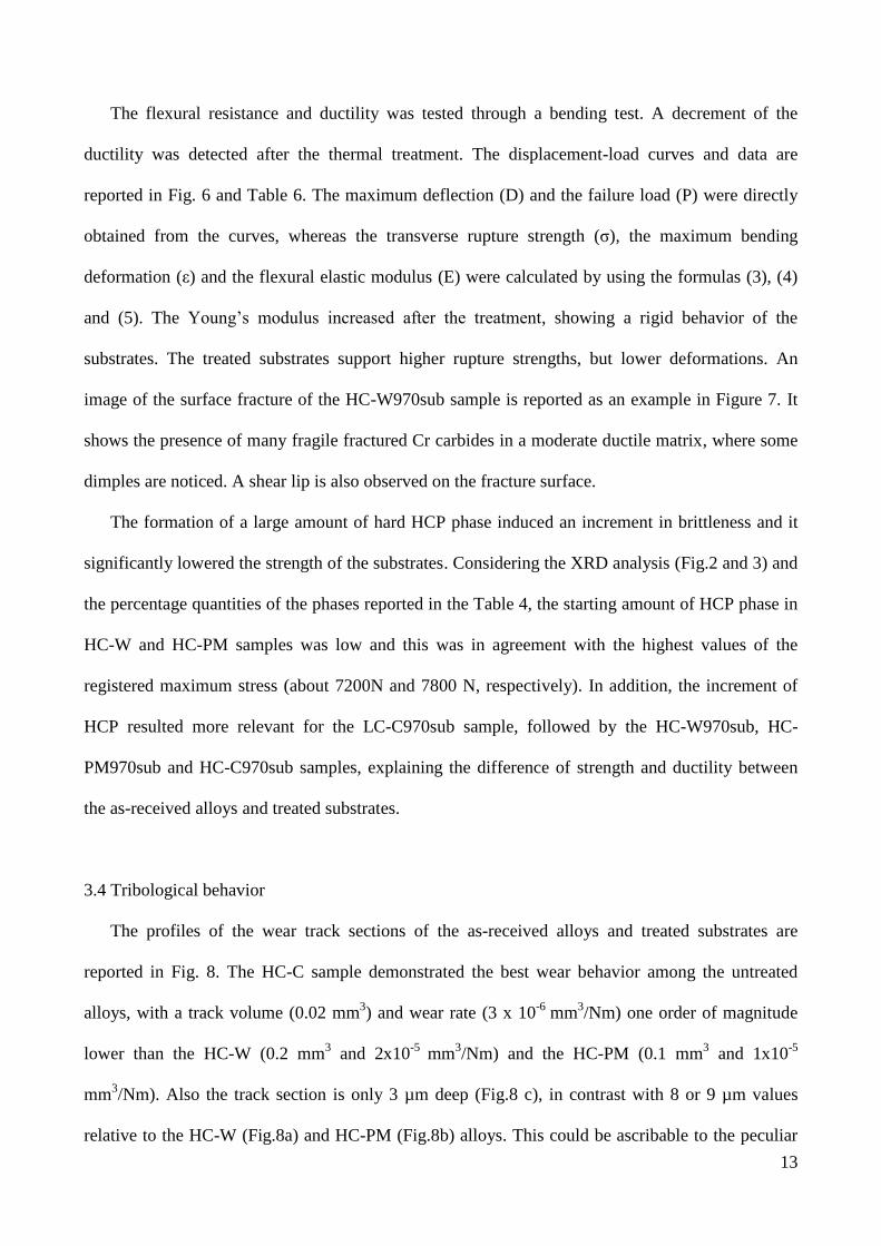
The flexural resistance and ductility was tested through a bending test. A decrement of the
ductility was detected after the thermal treatment. The displacement-load curves and data are
reported in Fig. 6 and Table 6. The maximum deflection (D) and the failure load (P) were directly
obtained from the curves, whereas the transverse rupture strength (σ), the maximum bending
deformation (ε) and the flexural elastic modulus (E) were calculated by using the formulas (3), (4)
and (5). The Young’s modulus increased after the treatment, showing a rigid behavior of the
substrates. The treated substrates support higher rupture strengths, but lower deformations. An
image of the surface fracture of the HC-W970sub sample is reported as an example in Figure 7. It
shows the presence of many fragile fractured Cr carbides in a moderate ductile matrix, where some
dimples are noticed. A shear lip is also observed on the fracture surface.
The formation of a large amount of hard HCP phase induced an increment in brittleness and it
significantly lowered the strength of the substrates. Considering the XRD analysis (Fig.2 and 3) and
the percentage quantities of the phases reported in the Table 4, the starting amount of HCP phase in
HC-W and HC-PM samples was low and this was in agreement with the highest values of the
registered maximum stress (about 7200N and 7800 N, respectively). In addition, the increment of
HCP resulted more relevant for the LC-C970sub sample, followed by the HC-W970sub, HC-
PM970sub and HC-C970sub samples, explaining the difference of strength and ductility between
the as-received alloys and treated substrates.
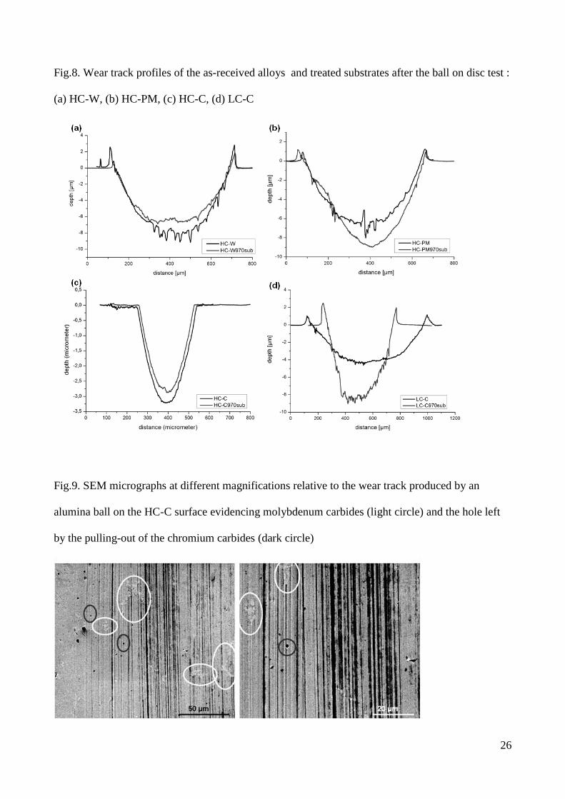
3.4 Tribological behavior
The profiles of the wear track sections of the as-received alloys and treated substrates are
reported in Fig. 8. The HC-C sample demonstrated the best wear behavior among the untreated
alloys, with a track volume (0.02 mm3) and wear rate (3 x 10
-6 mm
3/Nm) one order of magnitude
lower than the HC-W (0.2 mm3 and 2x10
-5 mm
3/Nm) and the HC-PM (0.1 mm
3 and 1x10
-5
mm3/Nm). Also the track section is only 3 µm deep (Fig.8 c), in contrast with 8 or 9 µm values
relative to the HC-W (Fig.8a) and HC-PM (Fig.8b) alloys. This could be ascribable to the peculiar

14
microstructure and carbide distribution of the cast alloys. The comparison with the literature [22,
23] is difficult, because a different counterpart, as well as applied load and sliding distance were
used. The track profile relative to the treated substrates (Fig.8) results almost overlapped to the as-
received alloys, except for the LC-C sample. In this case, the LC-C970sub sample (Fig.8d) exhibits
a narrower, but higher track section than the as-received sample. Even if the amount of the HCP
phase inside the bulk, induced by the thermal treatment, may enhance the tribological properties of
the material, no relevant differences were noticed in term of wear resistance in the alloys before and
after the thermal treatment. This could be explained with the fact that the HCP phase was formed
also in the untreated material by a strain-induced martensitic transformation during the wear test,
caused by the applied load [23]. Hence, the tribological results, obtained for the as-received alloys,
referred to a material containing on the surface an HCP amount higher than that evaluated through
XRD analysis. The two peaks visible at the edge of the tracks relative to the HC-W, HC-PM and
LC-C as received and treated alloys were correlated to displaced and piled up material, removed
with the ball passage.
The predominant wear mechanism consists in abrasion with the contribution of third-body
damage both before and after the thermal treatment. In fact, the typical features of the abrasion
wear, as scratches and grooves, are noticed inside the tracks of the high carbon cast alloys as
reported in Fig. 9. The sample surface was principally abraded by the passage of the hard alumina
ball which created deep scratches along its direction. In addition, it is well known that the mean
size, volume fraction and distribution of the carbides contribute to the final wear resistance. Hence
the Cr and Mo carbides, embedded into the alloys matrix, affected also the wear behavior of the as
received alloys, especially in the case of the high carbon content samples. Hard carbides could
crack, fracture and pull-out during wear in contact with another hard phase causing third body
damage. Moreover their high hardness is considered a relevant cause of abrasive damage. In any
case, if they have good coherency with the surrounding matrix might act as a barrier to the matrix
delamination [22]. Hence the improved wear performance of the HC-C alloy could be also
15
attributed to the presence of agglomerates and less numerous carbides inside the matrix, in
comparison with the larger number of them in the HC-W and HC-PM alloys. The Mo carbides
(light circle) are well visible in the wear track of the HC-C alloy (Fig.9) and a hole left by a Cr
carbide (dark circle), pulled out from the surface, is observed in the microphotograph at higher
magnification, on the right in Fig. 9. Cr and Co ions were found into the serum bovine, analyzed in
the previous authors’ work [30], after the wear tests comparing the solution used for the test
between alumina ball and as-received alloys and the test between alumina ball and Ta-coated
samples. In the first case, the metal ions amount was significantly higher than in the second case,
demonstrating that the tantalum coating deposited through thermal treatment in molten salt was able
to reduce the release of potential toxic metal ions. The thermal treatment should not influence the
ions release of the CoCrMo substrates, however other analysis will be performed in order to control
this aspect and the possible cytotoxic behavior.
4. Conclusions
In conclusion, the properties of the CoCrMo alloys are affected by the tested thermal treatment
in molten salts. The aim of the treatment was the formation of a Ta-rich coating, but its effects on
the substrates cannot be omitted.
Firstly, the temperature induced an increment in the amount of the HCP phase inside the
substrates, then it changed the grain size of the matrix. It did not influence the dimension,
distribution and size of the carbides. In addition, all the treated substrates were characterized by a
preferential orientations of the FCC phase. As a consequence, a decrement in the hardness,
especially for the HC alloys, and in the bending ductility was noticed after the thermal treatment.
An increment in the flexural strength was also observed after the thermal treatment. In contrast, no
significant differences in the tribological properties were obtained, comparing the as-received alloys
and treated substrates. The HCP phase was probably induced also onto the as-received alloys during
16
the wear tests, through a strain-induced mechanism of phase transformation, due to the applied
load. The tribological behavior is more strictly related to the carbide presence than to the
crystallographic structure. Further work will be needed in order to verify the eventual cytotoxicity
of the metal ions released during wear test.
Acknowledgements
Authors would like to thank Smith & Nephew Orthopaedics AG that contributed to the realization
of this study with the supply of CoCrMo alloys analysed in this work.
17
References
[1] A. Marti, Int. J. Care Injured 31 (2000) S-D18-21.
[2] M. Niinomi, Metall. Mater. Trans. A 33 (2002) 477-486.
[3] S.M. Kurtz, Elsevier Academic Press, San Diego (2004).
[4] A. Buford, T. Goswami, Mater. Des. 25 (2004) 385-393 .
[5] T.P. Schmalzried, J.J. Callaghan, J. Bone Jt. Surg. 81A (1999) 114-136.
[6] E. Ingham, J. Fisher, Biomaterials 26 (2005) 1271-1286.
[7] E.Ingham, J. Fisher, Proc. Instn. Mech. Engrs. H 214 (2000) 21-37.
[8] V.D. Shetty, R.N. Villar, Proc. Instn. Mech. Engrs. H 220 (2006) 371-377.
[9] P.J. Firkins, J.L. Tipper, E. Ingham, M.H. Stone, R. Farrar, J. Fisher, J. Biomec. 34 (2001)
1291–1298.
[10] Y. Yan, A. Neville, D. Dowson, Wear 263 (2007) 1105-1111.
[11] D.Sun, J.A. Wharton, R.J.K. Wood, L.Ma, W.M. Rainforth, Tribol. Int. 42 (2009) 99-110.
[12] A.G. Cobb, T.P. Schmalzreid, Proc. Instn. Mech. Engrs. H 220 (2006) 385- 398.
[13] W. T. Long, M.D., Iowa Orthop. J. 25 (2005) 10–16.
[14] J.L. Tipper, P.J. Firkins, A.A. Besong, P.S.M. Barbour, J. Nevelos, M.H. Stone, E. Ingham, J.
Fisher, Wear 250 (2001) 120-128.
[15] L. Savarino, D. Granchi, G. Ciapetti, E. Cenni, A. NardiPantoli, R. Rotini, C.A. Veronesi, N.
Baldini, A. Giunti, J. Biomed. Mater. Res.: Appl. Biomater. 63 (2002) 467-474.
[16] R.M. Urban, J.J. Jacobs, M.J. Tomlinson, J. Gavrilovic, J.Black, M. Peoc’h, J. Bone Jt. Surg.
82A (2000) 457-477.
[17] C.P. Case, V.G. Langkamer, C. James, M.R. Palmer, A.J. Kemp, P.F. Heap, L. Solomon,
J.Bone Jt. Surg. 76-B (1994) 701-712.
[18] C. Brown, J. Fisher, E. Ingham, Proc. Instn. Mech. Engrs. H 220 (2006) 355-369.
[19] O.L. Huk, I. Catelas, F. Mwale, J. Antoniou, D. J. Zukor, A. Petit, J. Arthroplast. 19 (2004) 84-
87.

18
[20] H.G. Willert, G.H. Buchhorn, A. Fayyaz, R. Flury, M. Windler, G. Köster, C. H. Lohmann,
J.Bone . Jt. Surg. 87 (2005) 28-36.
[21] M. Huber, G. Reinisch, G. Trettenhahn, K. Zweymuller, F. Lintner, Acta Biomater. 5 (2009)
172-180.
[22] R. Varano, J.D. Bobyn, J.B. Medley, S. Yue, Proc. Instn. Mech. Engrs. H 220 (2006) 145-159.
[23] A. Chiba, K. Kumagai, N. Nomura, S. Miyakawa, Acta Mater. 55 (2007) 1309-1318.
[24] A.J. Saldivar-Garcia, H.F. Lopez, J. Biomed. Mater. Res. A 74 (2005) 269-274 .
[25] A.J. Saldivar Garcia, A. Mani Medrano and A. Salinas Rodriguez, Scripta Mater. 40 (1999)
717-722.
[26] A.J. Saldivar Garcia, A. Mani Medrano and A. Salinas Rodriguez, Metall. Mater. Trans. 30A
(1999) 1177-1184.
[27] M. Herrera, Espinoza, J. Mendez, M. Castro, J. Lopez, J. Rendon, J. Mater. Sci.: Mater. Med.
16 (2005) 607-611.
[28] M. Caudillo, M. Herrera-Trejo, M. R. Castro, E. Ramirez, C. R. Gonzalez, J.J. Juarez, J.
Biomed. Mater. Res. 59 (2002) 378-385.
[29] J. Cawley, J.E.P. Metcalf, A.H. Jones, T.J. Band, D.S. Skupien, Wear 255 (2003) 999-1006.
[30] S. Spriano, E. Vernè, M.G. Faga, S. Bugliosi, G. Maina, Wear 259 (2005) 919-925.
[31] C. Balagna, S. Spriano, M.G. Faga, J. Nanosci. Nanotech. 11 (2011) 8994-9002.
[32] C. Balagna, M.G. Faga, S. Spriano, Mater. Sci. Eng. C 32 (2012) 887-895.
[33] S. Spriano, S. Bugliosi, WO 2006/038202A2 (2006).
[34] J. Black, Clin. Mater. 16 (1994) 167-173.
[35] B.R. Levine, S. Sporer, R.A. Poggie, C.J. Della Valle, J.J. Jacobs, Biomaterials 27 (2006)
4671-4681.
[36] D.M. Findlay, K. Welldon, G.J. Atkins, D.W. Howie, A.C.W. Zannettino, D. Bobyn,
Biomaterials 25 (2004) 2215-2227.

19
[37] M. Stiehler, M. Lind, T. Mygind, A. Baatrup, A. Dolatshashi-Pirouz, H. Li, M. Foss, F.
Besenbacher, M.Kassem, C. Bunger, J. Biomed. Mater. Res. A (2007) 448-458.
[38] S.M. Cardone, P. Kumar, C.A. Michaluk, H.D. Schwartz, Int. J. Refract. Met. Hard Mater. 13
(1995) 187-194.
[39] M.D. Bermudez, F. J. Carrion, G. Martınez-Nicolas, R. Lopez, Wear 258 (2005) 693–700.
[40] A. Robin, J. L. Rosa, Int. J. Refract. Met. Hard Mater. 18 (2000) 13-21.
[41] A.J. Saldivar-Garcia, H.F. Lopez, Scripta Mater. 45 (2001) 427-433.
[42] H.F. Lopez, A.J. Saldivar-Garcia, Metall. Mater. Trans. 39A (2008) 8-18.
[43] M. Sage, Ch. Guillaud, Rev. Met. 47 (1950) 139-145.
[44] D. Klarstrom, P. Crook, J. Wu, ASM Handbook 9, ASM International (2004) 762-774.
[45] ISO 3327:1982 (1982).
[46] ISO 7206-2:1996 (1996).

20
Figures
Fig.1. Comparison of the carbides distribution, size and dimensions before (on the left) and after (on
the right) the thermal treatment: (a,b) HC-W, (c,d) HC-PM, (e,f) HC-C, (g, h) LC-C. EDS analysis
referred to (i) Cr-carbide, (l) Mo-Carbide, (m) alloy area

21
Fig.2. XRD analysis of high carbon alloys comparing the diffractograms before and after the
thermal treatment, (a) HC-W and HC-W970sub, (b) HC-PM and HC-PM970sub, (c) HC-C and HC-
C970sub

22
Fig.3. XRD analysis of low carbon alloys, comparing the diffractograms before and after the
thermal treatment, (a) LC-W and LC-W970sub, (b) LC-C and LC-C970sub
23
Fig.4. Photographs of the microstructure of the alloys, before (on the left) and after (on the right)
thermal treatment: (a and b) HC-W, (c and d) HC-PM, (e and f) HC-C, (g and h) LC-C. Circle and
arrows indicate carbides and grain boundaries
24
Fig.5. SEM micrographs ofdark HCP phase nucleated close to carbides (circles) or at grain
boundaries (arrows) on (a) HC-C970sub and (b) LC-C970sub
Fig.6. Load-displacement curves relative to the 3-point bending test

25
Fig.7. SEM images relative to surface fracture of HC-W970sub after bending test. The circles
indicate fractured Cr-carbides
26
Fig.8. Wear track profiles of the as-received alloys and treated substrates after the ball on disc test :
(a) HC-W, (b) HC-PM, (c) HC-C, (d) LC-C
Fig.9. SEM micrographs at different magnifications relative to the wear track produced by an
alumina ball on the HC-C surface evidencing molybdenum carbides (light circle) and the hole left
by the pulling-out of the chromium carbides (dark circle)
27
Tables
Table 1
Dimensions of samples analyzed at 3-points bending test
Sample b (mm) d (mm)
HC-W 6.5 3.5
HC-W970sub 6.5 3.0
HC-PM 6.5 3.5
HC-PM970sub 6.5 3.0
HC-C 6.5 3.3
HC-C970sub 6.5 2.8
LC-C 6.5 2.9
LC-C970sub 6.5 2.5
Table2
Composition of the as-received CoCrMo alloys
Alloy Manufacturing process
EDS analysis Quantometer analysis
%wt.
Co
%wt
Cr
%wt
Mo
%wt
Ni
%wt
C
HC-W Wrought 62.5 30.6 6.4 0.5 0.25
HC-PM Powder Metallurgy 66.2 28.1 6 - 0.14
HC-C Casting 66.2 29.8 3.9 0.1 0.20
LC-W Wrought 65.0 29.0 5.8 0.2 < 0.01
LC-C Casting 64.1 33.5 2.4 - 0.07
Table 3
Roughness data relative to as received alloys and the substrates after the coating removal
Sample Ra (nm) Rq (nm) Rz (nm)
HC-W 2±0.5 3±1 19±5
HC-W970sub 2±0.5 3±1 15±3
HC-PM 1±0.2 2±1 10±2
HC-PM970sub 3±0.3 4±1 19±4
HC-C 6±1 9±1 60±6
HC-C970sub 3±1 4±2 22 ±10
LC-W 6±1 6±1 28±2
LC-W970sub 4±0.4 5±1 26±4
LC-C 3±2 4±2 25±10
LC-C970sub 3±0.4 3±1 17±5
28
Table 4
The amount of the cubic and hexagonal phases in the as-received alloys and in the treated
substrates, calculated in terms of percentage volume fraction with the three methods.
Sample
Volume fraction (%)
(1) (2) MAUD
FCC HCP FCC HCP FCC HCP
HC-W 99 1 99 1 97 ± 4 3 ± 0.3
HC-W970sub 57 43 75 25 55 ± 1 45 ± 1
HC-PM 81 19 87 13 70 ± 2 30 ± 1
HC-PM970sub 58 42 75 25 58 ± 1 42 ± 1
HC-C 74 26 68 32 44 ± 2 55 ± 3
HC-C970sub 10 90 70 30 37 ± 6 63 ± 9
LC-W 98 2 99 1 - -
LC-W970sub 85 15 87 13 54 ± 2 46 ± 2
LC-C 74 26 71 29 - -
LC-C970sub 15 85 39 61 15 ± 2 85 ± 8
Table 5
Micro-hardness values evaluated under loads of 100g and 500g and macro-hardness values
obtained under a load of 40kg.
Sample HV 100g HV 500g HV 40 kg
HC-W 594 ± 23 588 ± 27 450 ± 13
HC-W970sub 509 ± 39 469 ± 3 441 ± 16
HC-PM 587 ± 13 574 ± 14 520 ± 12
HC-PM970sub 538 ± 27 492 ± 10 474 ± 13
HC-C 398 ± 26 382 ± 10 315 ± 15
HC-C970sub 396 ± 10 378 ± 20 347 ± 6
LC-W 509 ± 5 445 ± 8 -
LC-W970sub 439 ±10 499 ± 11 409 ± 18
LC-C 384 ± 5 320 ± 7 267 ± 25
LC-C970sub 429 ± 12 429 ± 38 287 ± 5
Table 6
Data obtained from the 3-point bending test
Sample D (mm) P (N) σ (MPa) ε E (GPa)
HC-W 2.3 7412 2304 0.18 32.65
HC-W970sub 2.6 4919 2346 0.14 46.64
HC-PM 3.0 7692 2391 0.23 30.09
HC-PM970sub 2.3 5201 2480 0.12 46.14
HC-C 2.1 2814 984 0.15 18.73
HC-C970sub 2.2 2531 1386 0.11 34.14
LC-C 1.4 2624 828 0.18 10.76
LC-C970sub 2.0 1294 893 0.09 39.25