Embed Size (px)
Citation preview

POLARIS
RANGER
XP 700 4X4
RANGER 6X6
SERVICE
MANUAL
1GENERAL INFORMATION
2MAINTENANCE
3ENGINE
4FUEL INJECTION
5BODY / STEERING / SUSPENSION
6CLUTCHING
7FINAL DRIVE
8TRANSMISSION
BRAKES 9
ELECTRICAL 10
POLARIS
RANGER
XP 700 4X4
RANGER 6X6
SERVICE
MANUAL

GENERAL INFORMATION
CHAPTER 1GENERAL INFORMATION 1
MODEL INFORMATION . . . . . . . . . . . . . . . . . . . . . . . . . . . . . . . . . . . . . . . . . . . . . . . . . . 1.2MODEL IDENTIFICATION . . . . . . . . . . . . . . . . . . . . . . . . . . . . . . . . . . . . . . . . . . . . . . . . 1.2ENGINE DESIGNATION NUMBER . . . . . . . . . . . . . . . . . . . . . . . . . . . . . . . . . . . . . . . . . 1.2VIN IDENTIFICATION . . . . . . . . . . . . . . . . . . . . . . . . . . . . . . . . . . . . . . . . . . . . . . . . . . . 1.2ENGINE SERIAL NUMBER LOCATION . . . . . . . . . . . . . . . . . . . . . . . . . . . . . . . . . . . . . 1.2UNIT SERIAL NUMBER (VIN) LOCATION . . . . . . . . . . . . . . . . . . . . . . . . . . . . . . . . . . . 1.3TRANSMISSION I.D. NUMBER LOCATION . . . . . . . . . . . . . . . . . . . . . . . . . . . . . . . . . . 1.3
VEHICLE DIMENSIONS . . . . . . . . . . . . . . . . . . . . . . . . . . . . . . . . . . . . . . . . . . . . . . . . . . 1.4VEHICLE DIMENSIONS RANGER 4X4, 6X6. . . . . . . . . . . . . . . . . . . . . . . . . . . . . . . . . . 1.5
GENERAL SPECIFICATIONS. . . . . . . . . . . . . . . . . . . . . . . . . . . . . . . . . . . . . . . . . . . . . . 1.6 MODEL: RANGER XP 4X4 . . . . . . . . . . . . . . . . . . . . . . . . . . . . . . . . . . . . . . . . . . . 1.6 MODEL: RANGER XP 6X6 . . . . . . . . . . . . . . . . . . . . . . . . . . . . . . . . . . . . . . . . . . . 1.6 MODEL: RANGER XP 4X4 . . . . . . . . . . . . . . . . . . . . . . . . . . . . . . . . . . . . . . . . . . . 1.7 MODEL: RANGER XP 6X6 . . . . . . . . . . . . . . . . . . . . . . . . . . . . . . . . . . . . . . . . . . . 1.8
VEHICLE INFORMATION . . . . . . . . . . . . . . . . . . . . . . . . . . . . . . . . . . . . . . . . . . . . . . . . . 1.9PUBLICATION NUMBERS. . . . . . . . . . . . . . . . . . . . . . . . . . . . . . . . . . . . . . . . . . . . . . . . 1.9PAINT CODES . . . . . . . . . . . . . . . . . . . . . . . . . . . . . . . . . . . . . . . . . . . . . . . . . . . . . . . . . 1.9REPLACEMENT KEYS . . . . . . . . . . . . . . . . . . . . . . . . . . . . . . . . . . . . . . . . . . . . . . . . . . 1.9
SPECIAL TOOLS . . . . . . . . . . . . . . . . . . . . . . . . . . . . . . . . . . . . . . . . . . . . . . . . . . . . . . . 1.9MISC. SPECIFICATIONS AND CHARTS . . . . . . . . . . . . . . . . . . . . . . . . . . . . . . . . . . . . 1.10
CONVERSION TABLE . . . . . . . . . . . . . . . . . . . . . . . . . . . . . . . . . . . . . . . . . . . . . . . . . . 1.10STANDARD TORQUE SPECIFICATIONS. . . . . . . . . . . . . . . . . . . . . . . . . . . . . . . . . . . 1.11SAE TAP / DRILL SIZES . . . . . . . . . . . . . . . . . . . . . . . . . . . . . . . . . . . . . . . . . . . . . . . . 1.12METRIC TAP / DRILL SIZES . . . . . . . . . . . . . . . . . . . . . . . . . . . . . . . . . . . . . . . . . . . . . 1.12DECIMAL EQUIVALENTS . . . . . . . . . . . . . . . . . . . . . . . . . . . . . . . . . . . . . . . . . . . . . . . 1.12GLOSSARY OF TERMS. . . . . . . . . . . . . . . . . . . . . . . . . . . . . . . . . . . . . . . . . . . . . . . . . 1.13
1.1
GENERAL INFORMATION
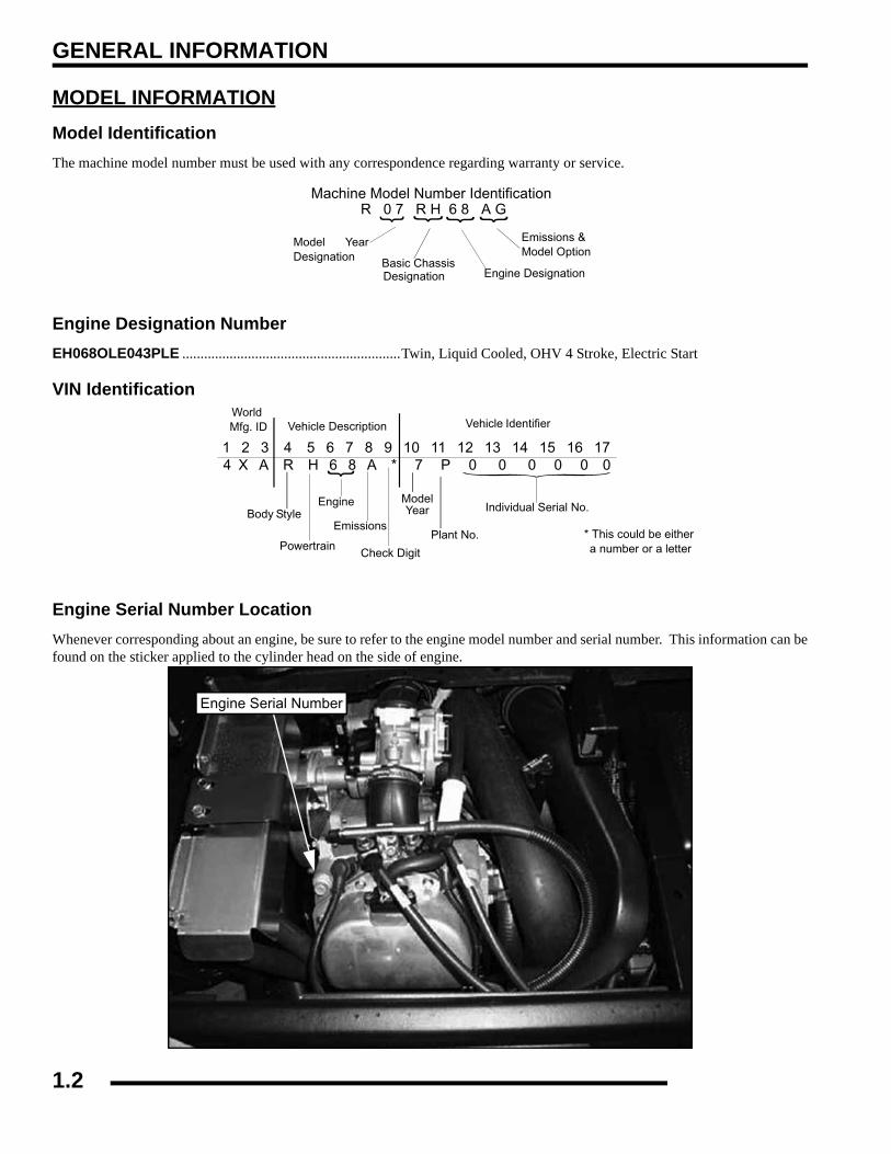
MODEL INFORMATIONModel IdentificationThe machine model number must be used with any correspondence regarding warranty or service.
Engine Designation NumberEH068OLE043PLE ............................................................Twin, Liquid Cooled, OHV 4 Stroke, Electric Start
VIN Identification
Engine Serial Number LocationWhenever corresponding about an engine, be sure to refer to the engine model number and serial number. This information can befound on the sticker applied to the cylinder head on the side of engine.
Machine Model Number Identification
Model YearDesignation Basic Chassis
Designation Engine Designation
Emissions & Model Option
R 0 7 R H 6 8 A G4 X A R H 6 8 A * 7 P 0 0 0 0 0 0
1 2 3 4 5 6 7 8 9 10 11 12 13 14 15 16 17
World Mfg. ID
Engine
Vehicle Description Vehicle Identifier Check Digit
ModelYear Body Style
Plant No.
Individual Serial No.
* This could be either a number or a letterPowertrain
Emissions
AEngine Serial Number
1.2
GENERAL INFORMATION
1
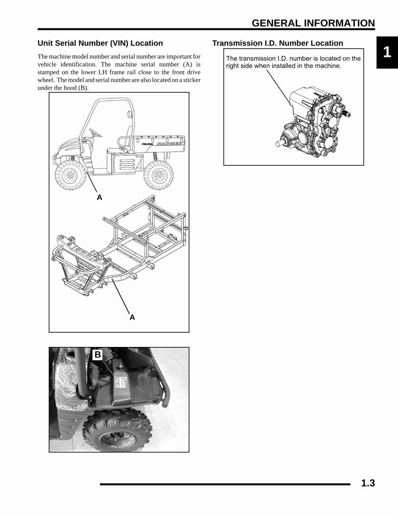
Unit Serial Number (VIN) LocationThe machine model number and serial number are important forvehicle identification. The machine serial number (A) isstamped on the lower LH frame rail close to the front drivewheel. The model and serial number are also located on a stickerunder the hood (B).Transmission I.D. Number Location
A
A
A
B
The transmission I.D. number is located on the right side when installed in the machine.
1.3
GENERAL INFORMATION
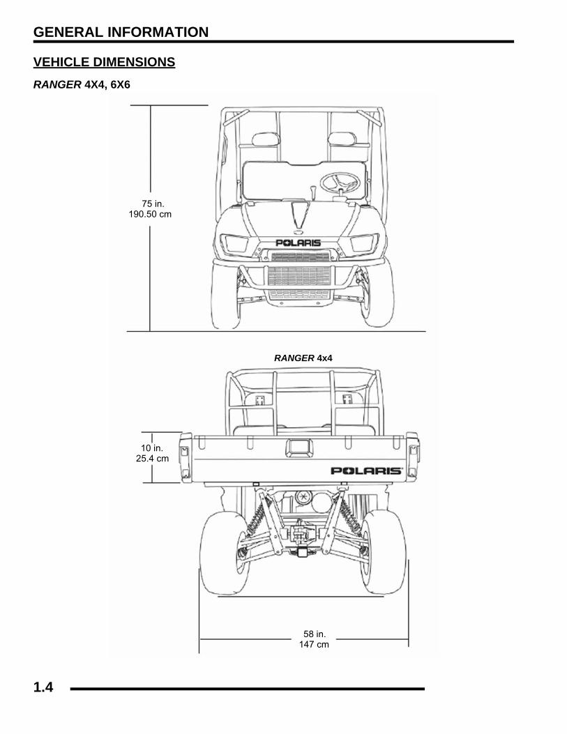
VEHICLE DIMENSIONSRANGER 4X4, 6X6
75 in.190.50 cm
10 in.25.4 cm
58 in.147 cm
RANGER 4x4
1.4

GENERAL INFORMATION
1
Vehicle Dimensions RANGER 4X4, 6X6120 in.305 cm
58 in.147 cm
27 in. 69 cm
90 in.229 cm
113 in.287 cm
58 in.147 cm
76 in.193 cm
1.5

GENERAL INFORMATION
GENERAL SPECIFICATIONS
MODEL: RANGER XP 4X4MODEL NUMBER: R07RH68AD,AG,AH,AK,AL,AWENGINE MODEL: EH068OLE
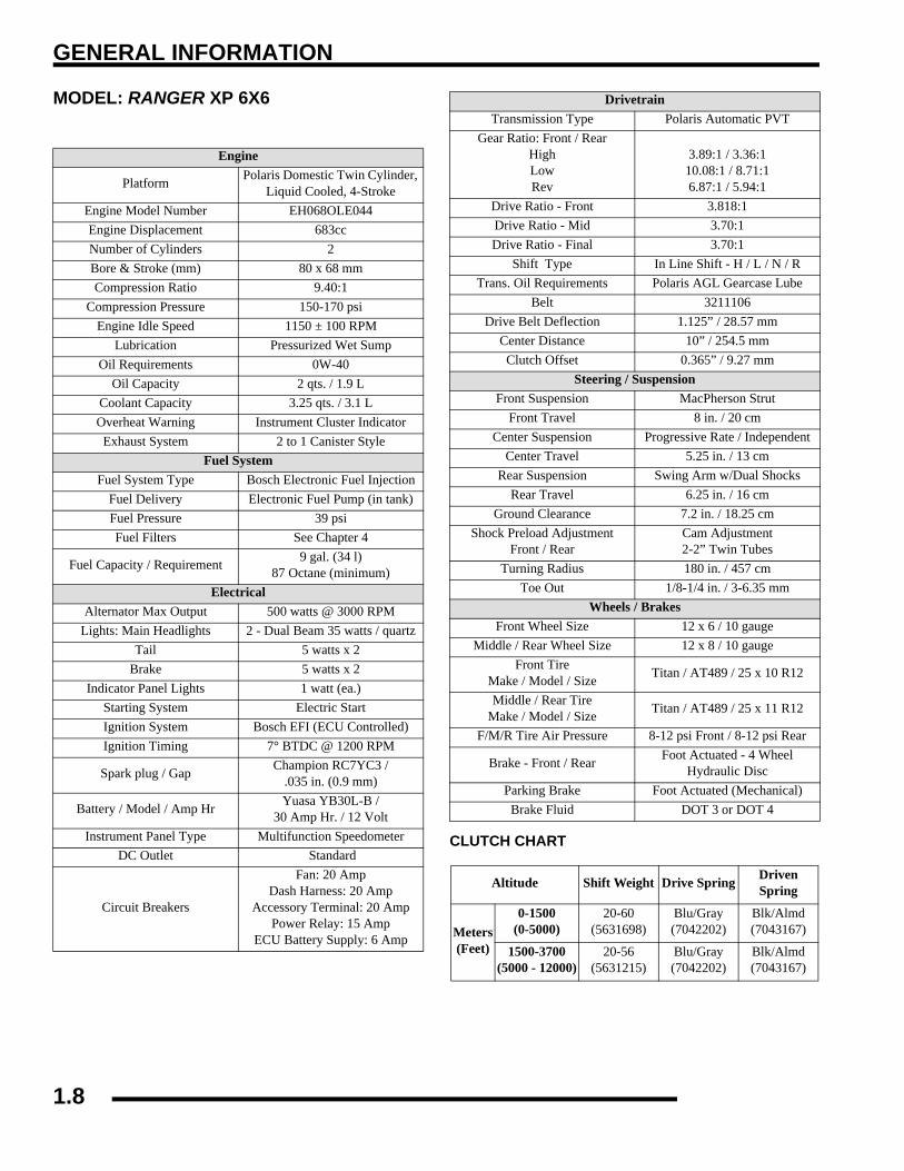
MODEL: RANGER XP 6X6MODEL NUMBER: R07RF68AFENGINE MODEL: EH068OLE
Category Dimension / CapacityLength 113 in. / 287 cmWidth 60 in. / 152.4 cmHeight 75 in. / 190.5 cmWheel Base 76 in. / 193 cmGround Clearance 11.5 in. / (29 cm)Turning Radius 132 in. / 335 cmDry Weight 1185 lbs. / 537 kgGross Vehicle Weight 2750 lbs. / 1247 kgCargo Box Capacity 1000 lbs. / 454 kg
Cargo Box Dimensions58 x 42 x 10 in.
(147 x 106.7 x 25.4 cm)
Vehicle Payload1500 lbs. / 681 kg
(Includes driver and two passengers - 500 lbs. / 227kg)
Hitch Towing Capacity 1500 lbs. / 681 kgHitch Tongue Capacity 150 lbs. / 68 kg
Category Dimension / CapacityLength 120 in. / 305 cmWidth 60 in. / 152.4 cmHeight 75 in. / 190.5 cmWheel Base 90 in. / 229 cmGround Clearance 7.2 in. / (18.25 cm)Turning Radius 180 in. / 457 cmDry Weight 1410 lbs. / 640 kgGross Vehicle Weight 2900 lbs. / 1315 kgCargo Box Capacity 1250 lbs. / 567 kg
Cargo Box Dimensions58 x 48 x 10 in.
(147 x 122 x 25.4 cm)
Vehicle Payload1750 lbs. / 794 kg
(Includes driver and two passengers - 500 lbs. / 227kg)
Hitch Towing Capacity 1750 lbs. / 794 kgHitch Tongue Capacity 150 lbs. / 68 kg
1.6
GENERAL INFORMATION
1
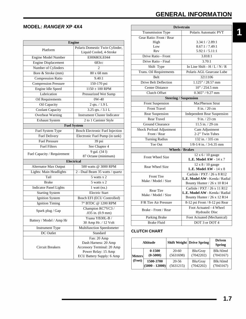
MODEL: RANGER XP 4X4MODEL NUMBER: R07RH68AD,AG,AH,AK,AL,AWENGINE MODEL: EH068OLECLUTCH CHART
Engine
Platform Polaris Domestic Twin Cylinder, Liquid Cooled, 4-Stroke
Engine Model Number EH068OLE044Engine Displacement 683ccNumber of Cylinders 2Bore & Stroke (mm) 80 x 68 mmCompression Ratio 9.40:1
Compression Pressure 150-170 psiEngine Idle Speed 1150 ± 100 RPM
Lubrication Pressurized Wet SumpOil Requirements 0W-40
Oil Capacity 2 qts. / 1.9 LCoolant Capacity 3.25 qts. / 3.1 LOverheat Warning Instrument Cluster IndicatorExhaust System 2 to 1 Canister Style
Fuel SystemFuel System Type Bosch Electronic Fuel Injection
Fuel Delivery Electronic Fuel Pump (in tank)Fuel Pressure 39 psiFuel Filters See Chapter 4
Fuel Capacity / Requirement 9 gal. (34 l)87 Octane (minimum)
ElectricalAlternator Max Output 500 watts @ 3000 RPM
Lights: Main Headlights 2 - Dual Beam 35 watts / quartzTail 5 watts x 2
Brake 5 watts x 2Indicator Panel Lights 1 watt (ea.)
Starting System Electric StartIgnition System Bosch EFI (ECU Controlled)Ignition Timing 7° BTDC @ 1200 RPM
Spark plug / Gap Champion RC7YC3 / .035 in. (0.9 mm)
Battery / Model / Amp Hr Yuasa YB30L-B /30 Amp Hr. / 12 Volt
Instrument Type Multifunction SpeedometerDC Outlet Standard
Circuit Breakers
Fan: 20 Amp Dash Harness: 20 Amp
Accessory Terminal: 20 Amp Power Relay: 15 Amp
ECU Battery Supply: 6 Amp
DrivetrainTransmission Type Polaris Automatic PVT
Gear Ratio: Front / RearHighLowRev
3.34:1 / 2.89:18.67:1 / 7.49:15.92:1 / 5.11:1
Drive Ratio - Front 3.818:1Drive Ratio - Final 3.70:1
Shift Type In Line Shift - H / L / N / RTrans. Oil Requirements Polaris AGL Gearcase Lube
Belt 3211106Drive Belt Deflection 1.125” / 28.57 mm
Center Distance 10” / 254.5 mmClutch Offset 0.365” / 9.27 mm
Steering / SuspensionFront Suspension MacPherson Strut
Front Travel 8 in. / 20 cmRear Suspension Independent Rear Suspension
Rear Travel 9 in. / 23 cmGround Clearance 11.5 in. / 29 cm
Shock Preload AdjustmentFront / Rear
Cam Adjustment2-2” Twin Tubes
Turning Radius 132 in. / 335 cmToe Out 1/8-1/4 in. / 3-6.35 mm
Wheels / Brakes
Front Wheel Size 12 x 6 / 10 gaugeL.E. Model AW - 14 x 7
Rear Wheel Size 12 x 8 / 10 gaugeL.E. Model AW - 14 x 8
Front TireMake / Model / Size
Carlisle / PXT / 26 x 8 R12L.E. Model AW - Kenda / Radial
Bounty Hunter / 26 x 10 R14
Rear TireMake / Model / Size
Carlisle / PXT / 26 x 11 R12L.E. Model AW - Kenda / Radial
Bounty Hunter / 26 x 12 R14F/R Tire Air Pressure 8-12 psi Front / 8-12 psi Rear
Brake - Front / Rear Foot Actuated - 4 Wheel Hydraulic Disc
Parking Brake Foot Actuated (Mechanical)Brake Fluid DOT 3 or DOT 4
Altitude Shift Weight Drive Spring Driven Spring
Meters(Feet)
0-1500(0-5000)
20-60(5631698)
Blu/Gray(7042202)
Blk/Almd(7043167)
1500-3700(5000 - 12000)
20-56(5631215)
Blu/Gray(7042202)
Blk/Almd(7043167)
1.7
GENERAL INFORMATION
MODEL: RANGER XP 6X6MODEL NUMBER: R07RF68AFENGINE MODEL: EH068OLE
CLUTCH CHART
Engine
Platform Polaris Domestic Twin Cylinder, Liquid Cooled, 4-Stroke
Engine Model Number EH068OLE044Engine Displacement 683ccNumber of Cylinders 2Bore & Stroke (mm) 80 x 68 mmCompression Ratio 9.40:1
Compression Pressure 150-170 psiEngine Idle Speed 1150 ± 100 RPM
Lubrication Pressurized Wet SumpOil Requirements 0W-40
Oil Capacity 2 qts. / 1.9 LCoolant Capacity 3.25 qts. / 3.1 LOverheat Warning Instrument Cluster Indicator
Exhaust System 2 to 1 Canister StyleFuel System
Fuel System Type Bosch Electronic Fuel InjectionFuel Delivery Electronic Fuel Pump (in tank)Fuel Pressure 39 psiFuel Filters See Chapter 4
Fuel Capacity / Requirement 9 gal. (34 l)87 Octane (minimum)
ElectricalAlternator Max Output 500 watts @ 3000 RPM
Lights: Main Headlights 2 - Dual Beam 35 watts / quartzTail 5 watts x 2
Brake 5 watts x 2Indicator Panel Lights 1 watt (ea.)
Starting System Electric StartIgnition System Bosch EFI (ECU Controlled)Ignition Timing 7° BTDC @ 1200 RPM
Spark plug / Gap Champion RC7YC3 / .035 in. (0.9 mm)
Battery / Model / Amp Hr Yuasa YB30L-B /30 Amp Hr. / 12 Volt
Instrument Panel Type Multifunction SpeedometerDC Outlet Standard
Circuit Breakers
Fan: 20 Amp Dash Harness: 20 Amp
Accessory Terminal: 20 Amp Power Relay: 15 Amp
ECU Battery Supply: 6 Amp
DrivetrainTransmission Type Polaris Automatic PVT
Gear Ratio: Front / RearHighLowRev
3.89:1 / 3.36:110.08:1 / 8.71:16.87:1 / 5.94:1
Drive Ratio - Front 3.818:1Drive Ratio - Mid 3.70:1Drive Ratio - Final 3.70:1
Shift Type In Line Shift - H / L / N / RTrans. Oil Requirements Polaris AGL Gearcase Lube
Belt 3211106Drive Belt Deflection 1.125” / 28.57 mm
Center Distance 10” / 254.5 mmClutch Offset 0.365” / 9.27 mm
Steering / SuspensionFront Suspension MacPherson Strut
Front Travel 8 in. / 20 cmCenter Suspension Progressive Rate / Independent
Center Travel 5.25 in. / 13 cmRear Suspension Swing Arm w/Dual Shocks
Rear Travel 6.25 in. / 16 cmGround Clearance 7.2 in. / 18.25 cm
Shock Preload AdjustmentFront / Rear
Cam Adjustment2-2” Twin Tubes
Turning Radius 180 in. / 457 cmToe Out 1/8-1/4 in. / 3-6.35 mm
Wheels / BrakesFront Wheel Size 12 x 6 / 10 gauge
Middle / Rear Wheel Size 12 x 8 / 10 gaugeFront Tire
Make / Model / Size Titan / AT489 / 25 x 10 R12
Middle / Rear TireMake / Model / Size Titan / AT489 / 25 x 11 R12
F/M/R Tire Air Pressure 8-12 psi Front / 8-12 psi Rear
Brake - Front / Rear Foot Actuated - 4 Wheel Hydraulic Disc
Parking Brake Foot Actuated (Mechanical)Brake Fluid DOT 3 or DOT 4
Altitude Shift Weight Drive Spring Driven Spring
Meters(Feet)
0-1500(0-5000)
20-60(5631698)
Blu/Gray(7042202)
Blk/Almd(7043167)
1500-3700(5000 - 12000)
20-56(5631215)
Blu/Gray(7042202)
Blk/Almd(7043167)
1.8
GENERAL INFORMATION
1
VPNOTE:
NOTE: www.purepolaris.com.
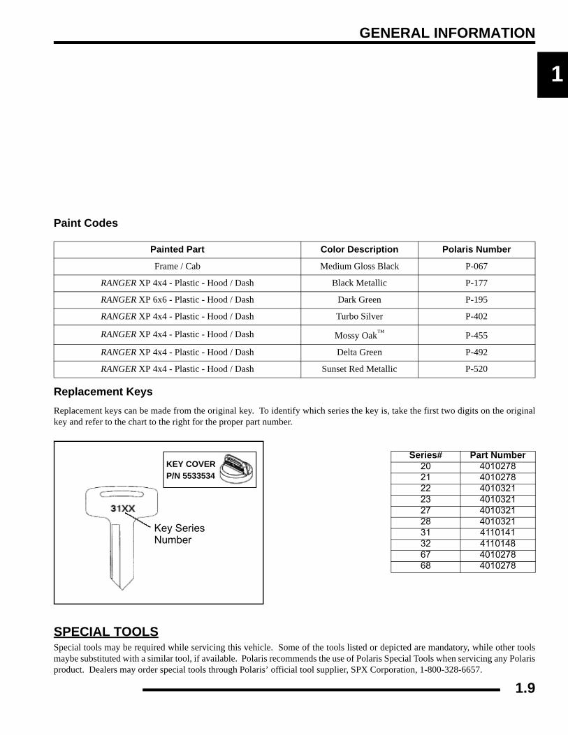
Paint Codes
Replacement KeysReplacement keys can be made from the original key. To identify which series the key is, take the first two digits on the originalkey and refer to the chart to the right for the proper part number.
SPECIAL TOOLSSpecial tools may be required while servicing this vehicle. Some of the tools listed or depicted are mandatory, while other toolsmaybe substituted with a similar tool, if available. Polaris recommends the use of Polaris Special Tools when servicing any Polarisproduct. Dealers may order special tools through Polaris’ official tool supplier, SPX Corporation, 1-800-328-6657.
M
20
20
Painted Part Color Description Polaris Number
Frame / Cab Medium Gloss Black P-067
RANGER XP 4x4 - Plastic - Hood / Dash Black Metallic P-177
RANGER XP 6x6 - Plastic - Hood / Dash Dark Green P-195
RANGER XP 4x4 - Plastic - Hood / Dash Turbo Silver P-402
RANGER XP 4x4 - Plastic - Hood / Dash Mossy Oak™ P-455
RANGER XP 4x4 - Plastic - Hood / Dash Delta Green P-492
RANGER XP 4x4 - Plastic - Hood / Dash Sunset Red Metallic P-520
Series# Part Number20 401027821 401027822 401032123 401032127 401032128 401032131 411014132 411014867 401027868 4010278
Key SeriesNumber
KEY COVERP/N 5533534
1.9

GENERAL INFORMATION
MISC. SPECIFICATIONS AND CHARTSConversion Table
°C to °F: 9 (°C + 40) ÷ 5 - 40 = °F °F to °C: (°F + 40) ÷ 9 - 40 = °C
1.10
GENERAL INFORMATION
1
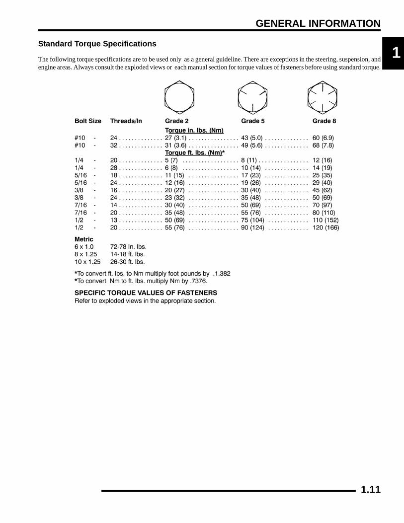
Standard Torque SpecificationsThe following torque specifications are to be used only as a general guideline. There are exceptions in the steering, suspension, andengine areas. Always consult the exploded views or each manual section for torque values of fasteners before using standard torque.
1.11
GENERAL INFORMATION
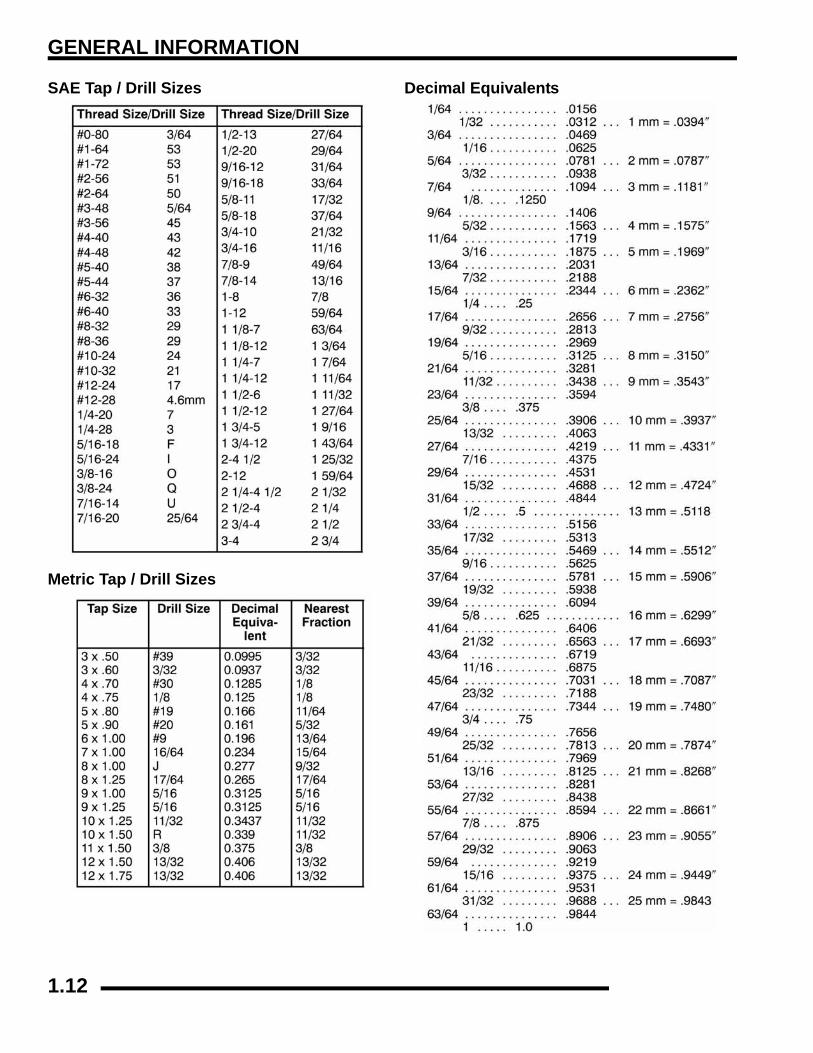
SAE Tap / Drill Sizes
Metric Tap / Drill Sizes
Decimal Equivalents
1.12
GENERAL INFORMATION
1
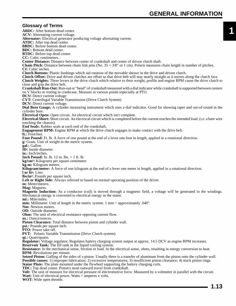
Glossary of TermsABDC: After bottom dead center.ACV: Alternating current voltage.Alternator: Electrical generator producing voltage alternating current.ATDC: After top dead center.BBDC: Before bottom dead center.BDC: Bottom dead center.BTDC: Before top dead center.CC: Cubic centimeters.Center Distance: Distance between center of crankshaft and center of driven clutch shaft.Chain Pitch: Distance between chain link pins (No. 35 = 3/8" or 1 cm). Polaris measures chain length in number of pitches.CI: Cubic inches.Clutch Buttons: Plastic bushings which aid rotation of the movable sheave in the drive and driven clutch.Clutch Offset: Drive and driven clutches are offset so that drive belt will stay nearly straight as it moves along the clutch face.Clutch Weights: Three levers in the drive clutch which relative to their weight, profile and engine RPM cause the drive clutch toclose and grip the drive belt.Crankshaft Run-Out: Run-out or "bend" of crankshaft measured with a dial indicator while crankshaft is supported between centerson V blocks or resting in crankcase. Measure at various points especially at PTO.DCV: Direct current voltageCVT: Centrifugal Variable Transmission (Drive Clutch System)DCV: Direct current voltage.Dial Bore Gauge: A cylinder measuring instrument which uses a dial indicator. Good for showing taper and out-of-round in thecylinder bore.Electrical Open: Open circuit. An electrical circuit which isn't complete.Electrical Short: Short circuit. An electrical circuit which is completed before the current reaches the intended load. (i.e. a bare wiretouching the chassis).End Seals: Rubber seals at each end of the crankshaft.Engagement RPM: Engine RPM at which the drive clutch engages to make contact with the drive belt.ft.: Foot/feet.Foot Pound: Ft. lb. A force of one pound at the end of a lever one foot in length, applied in a rotational direction.g: Gram. Unit of weight in the metric system.gal.: Gallon.ID: Inside diameter.in.: Inch/inches.Inch Pound: In. lb. 12 in. lbs. = 1 ft. lb.kg/cm²: Kilograms per square centimeter.kg-m: Kilogram meters.Kilogram/meter: A force of one kilogram at the end of a lever one meter in length, applied in a rotational direction.l or ltr: Liter.lbs/in²: Pounds per square inch.Left or Right Side: Always referred to based on normal operating position of the driver.m: Meter/meters.Mag: Magneto.Magnetic Induction: As a conductor (coil) is moved through a magnetic field, a voltage will be generated in the windings.Mechanical energy is converted to electrical energy in the stator.mi.: Mile/miles.mm: Millimeter. Unit of length in the metric system. 1 mm = approximately .040".Nm: Newton meters.OD: Outside diameter.Ohm: The unit of electrical resistance opposing current flow.oz.: Ounce/ounces.Piston Clearance: Total distance between piston and cylinder wall.psi.: Pounds per square inch.PTO: Power take off.PVT: Polaris Variable Transmission (Drive Clutch system)qt.: Quart/quarts.Regulator: Voltage regulator. Regulates battery charging system output at approx. 14.5 DCV as engine RPM increases.Reservoir Tank: The fill tank in the liquid cooling system.Resistance: In the mechanical sense, friction or load. In the electrical sense, ohms, resulting in energy conversion to heat.RPM: Revolutions per minute.Seized Piston: Galling of the sides of a piston. Usually there is a transfer of aluminum from the piston onto the cylinder wall.Possible causes: 1) improper lubrication; 2) excessive temperatures; 3) insufficient piston clearance; 4) stuck piston rings.Stator Plate: The plate mounted under the flywheel supporting the battery charging coils.TDC: Top dead center. Piston's most outward travel from crankshaft.Volt: The unit of measure for electrical pressure of electromotive force. Measured by a voltmeter in parallel with the circuit.Watt: Unit of electrical power. Watts = amperes x volts.WOT: Wide open throttle.1.13

GENERAL INFORMATION
CHAPTER 2GENERAL INFORMATION
2
PERIODIC MAINTENANCE CHART. . . . . . . . . . . . . . . . . . . . . . . . . . . . . . . . . . . . . . . . . 2.3PERIODIC MAINTENANCE OVERVIEW. . . . . . . . . . . . . . . . . . . . . . . . . . . . . . . . . . . . . 2.3MAINTENANCE CHART KEY . . . . . . . . . . . . . . . . . . . . . . . . . . . . . . . . . . . . . . . . . . . . . 2.3PRE-RIDE - 25 HOUR MAINTENANCE INTERVAL . . . . . . . . . . . . . . . . . . . . . . . . . . . . 2.450 - 100 HOUR MAINTENANCE INTERVAL . . . . . . . . . . . . . . . . . . . . . . . . . . . . . . . . . . 2.5100 - 300 HOUR MAINTENANCE INTERVAL . . . . . . . . . . . . . . . . . . . . . . . . . . . . . . . . . 2.6GENERAL COMPONENT LOCATIONS . . . . . . . . . . . . . . . . . . . . . . . . . . . . . . . . . . . . . . 2.7RH SIDE AND DASH VIEW (4X4) . . . . . . . . . . . . . . . . . . . . . . . . . . . . . . . . . . . . . . . . . . 2.7LH SIDE AND REAR VIEW (4X4) . . . . . . . . . . . . . . . . . . . . . . . . . . . . . . . . . . . . . . . . . . 2.8LH SIDE AND RH SIDE VIEWS (6X6) . . . . . . . . . . . . . . . . . . . . . . . . . . . . . . . . . . . . . . . 2.9
SERVICE PRODUCTS AND LUBES. . . . . . . . . . . . . . . . . . . . . . . . . . . . . . . . . . . . . . . . 2.10POLARIS LUBRICANTS, MAINTENANCE AND SERVICE PRODUCTS . . . . . . . . . . . 2.10
MAINTENANCE REFERENCES . . . . . . . . . . . . . . . . . . . . . . . . . . . . . . . . . . . . . . . . . . . 2.11MAINTENANCE REFERENCES, CONTINUED. . . . . . . . . . . . . . . . . . . . . . . . . . . . . . . 2.12
GENERAL VEHICLE INSPECTION AND MAINTENANCE. . . . . . . . . . . . . . . . . . . . . . . 2.13PRE-RIDE / DAILY INSPECTION . . . . . . . . . . . . . . . . . . . . . . . . . . . . . . . . . . . . . . . . . 2.13FRAME, NUTS, BOLTS, AND FASTENERS . . . . . . . . . . . . . . . . . . . . . . . . . . . . . . . . . 2.13SHIFT LINKAGE INSPECTION / ADJUSTMENT. . . . . . . . . . . . . . . . . . . . . . . . . . . . . . 2.13
FUEL SYSTEM AND AIR INTAKE . . . . . . . . . . . . . . . . . . . . . . . . . . . . . . . . . . . . . . . . . 2.14FUEL SYSTEM. . . . . . . . . . . . . . . . . . . . . . . . . . . . . . . . . . . . . . . . . . . . . . . . . . . . . . . . 2.14FUEL LINES . . . . . . . . . . . . . . . . . . . . . . . . . . . . . . . . . . . . . . . . . . . . . . . . . . . . . . . . . . 2.14FUEL FILTER . . . . . . . . . . . . . . . . . . . . . . . . . . . . . . . . . . . . . . . . . . . . . . . . . . . . . . . . . 2.14VENT LINES. . . . . . . . . . . . . . . . . . . . . . . . . . . . . . . . . . . . . . . . . . . . . . . . . . . . . . . . . . 2.14THROTTLE PEDAL INSPECTION . . . . . . . . . . . . . . . . . . . . . . . . . . . . . . . . . . . . . . . . . 2.14THROTTLE FREEPLAY ADJUSTMENT . . . . . . . . . . . . . . . . . . . . . . . . . . . . . . . . . . . . 2.15AIR FILTER SERVICE . . . . . . . . . . . . . . . . . . . . . . . . . . . . . . . . . . . . . . . . . . . . . . . . . . 2.15AIR INTAKE INSPECTION. . . . . . . . . . . . . . . . . . . . . . . . . . . . . . . . . . . . . . . . . . . . . . . 2.16
ENGINE . . . . . . . . . . . . . . . . . . . . . . . . . . . . . . . . . . . . . . . . . . . . . . . . . . . . . . . . . . . . . . 2.17COMPRESSION AND LEAKDOWN TEST. . . . . . . . . . . . . . . . . . . . . . . . . . . . . . . . . . . 2.17BREATHER HOSE INSPECTION . . . . . . . . . . . . . . . . . . . . . . . . . . . . . . . . . . . . . . . . . 2.17ENGINE OIL LEVEL . . . . . . . . . . . . . . . . . . . . . . . . . . . . . . . . . . . . . . . . . . . . . . . . . . . . 2.17ENGINE OIL AND FILTER CHANGE. . . . . . . . . . . . . . . . . . . . . . . . . . . . . . . . . . . . . . . 2.18EXHAUST PIPE . . . . . . . . . . . . . . . . . . . . . . . . . . . . . . . . . . . . . . . . . . . . . . . . . . . . . . . 2.19
TRANSMISSION AND GEARCASES . . . . . . . . . . . . . . . . . . . . . . . . . . . . . . . . . . . . . . . 2.20TRANSMISSION LUBRICATION . . . . . . . . . . . . . . . . . . . . . . . . . . . . . . . . . . . . . . . . . 2.20FRONT GEARCASE LUBRICATION (4X4) . . . . . . . . . . . . . . . . . . . . . . . . . . . . . . . . . . 2.21MIDDLE GEARCASE LUBRICATION (6X6) . . . . . . . . . . . . . . . . . . . . . . . . . . . . . . . . . 2.22REAR GEARCASE LUBRICATION (4X4) . . . . . . . . . . . . . . . . . . . . . . . . . . . . . . . . . . . 2.23REAR GEARCASE LUBRICATION (6X6) . . . . . . . . . . . . . . . . . . . . . . . . . . . . . . . . . . . 2.24
COOLING SYSTEM. . . . . . . . . . . . . . . . . . . . . . . . . . . . . . . . . . . . . . . . . . . . . . . . . . . . . 2.25LIQUID COOLING SYSTEM OVERVIEW . . . . . . . . . . . . . . . . . . . . . . . . . . . . . . . . . . . 2.25COOLANT LEVEL INSPECTION . . . . . . . . . . . . . . . . . . . . . . . . . . . . . . . . . . . . . . . . . . 2.25RADIATOR COOLANT LEVEL INSPECTION . . . . . . . . . . . . . . . . . . . . . . . . . . . . . . . . 2.26COOLANT STRENGTH / TYPE . . . . . . . . . . . . . . . . . . . . . . . . . . . . . . . . . . . . . . . . . . . 2.26COOLING SYSTEM PRESSURE TEST. . . . . . . . . . . . . . . . . . . . . . . . . . . . . . . . . . . . . 2.26COOLING SYSTEM HOSES . . . . . . . . . . . . . . . . . . . . . . . . . . . . . . . . . . . . . . . . . . . . . 2.26RADIATOR . . . . . . . . . . . . . . . . . . . . . . . . . . . . . . . . . . . . . . . . . . . . . . . . . . . . . . . . . . . 2.27COOLANT DRAIN / RADIATOR REMOVAL . . . . . . . . . . . . . . . . . . . . . . . . . . . . . . . . . 2.27
2.1

GENERAL INFORMATION
FINAL DRIVE / WHEEL AND TIRE . . . . . . . . . . . . . . . . . . . . . . . . . . . . . . . . . . . . . . . . . 2.27WHEEL, HUB, AND SPINDLE TORQUE TABLE. . . . . . . . . . . . . . . . . . . . . . . . . . . . . . 2.27CV SHAFT BOOT INSPECTION . . . . . . . . . . . . . . . . . . . . . . . . . . . . . . . . . . . . . . . . . . 2.28WHEEL REMOVAL . . . . . . . . . . . . . . . . . . . . . . . . . . . . . . . . . . . . . . . . . . . . . . . . . . . . 2.28WHEEL INSTALLATION . . . . . . . . . . . . . . . . . . . . . . . . . . . . . . . . . . . . . . . . . . . . . . . . 2.28TIRE INSPECTION. . . . . . . . . . . . . . . . . . . . . . . . . . . . . . . . . . . . . . . . . . . . . . . . . . . . . 2.28TIRE PRESSURE. . . . . . . . . . . . . . . . . . . . . . . . . . . . . . . . . . . . . . . . . . . . . . . . . . . . . . 2.29
ELECTRICAL AND IGNITION SYSTEM . . . . . . . . . . . . . . . . . . . . . . . . . . . . . . . . . . . . . 2.29BATTERY MAINTENANCE . . . . . . . . . . . . . . . . . . . . . . . . . . . . . . . . . . . . . . . . . . . . . . 2.29BATTERY FLUID LEVEL (CONVENTIONAL BATTERY) . . . . . . . . . . . . . . . . . . . . . . . 2.29BATTERY REMOVAL. . . . . . . . . . . . . . . . . . . . . . . . . . . . . . . . . . . . . . . . . . . . . . . . . . . 2.29BATTERY INSTALLATION. . . . . . . . . . . . . . . . . . . . . . . . . . . . . . . . . . . . . . . . . . . . . . . 2.30BATTERY STORAGE. . . . . . . . . . . . . . . . . . . . . . . . . . . . . . . . . . . . . . . . . . . . . . . . . . . 2.30BATTERY CHARGING. . . . . . . . . . . . . . . . . . . . . . . . . . . . . . . . . . . . . . . . . . . . . . . . . . 2.30SPARK PLUG SERVICE . . . . . . . . . . . . . . . . . . . . . . . . . . . . . . . . . . . . . . . . . . . . . . . . 2.30ENGINE TO FRAME GROUND . . . . . . . . . . . . . . . . . . . . . . . . . . . . . . . . . . . . . . . . . . . 2.31
STEERING AND SUSPENSION . . . . . . . . . . . . . . . . . . . . . . . . . . . . . . . . . . . . . . . . . . . 2.31STEERING . . . . . . . . . . . . . . . . . . . . . . . . . . . . . . . . . . . . . . . . . . . . . . . . . . . . . . . . . . . 2.31TIE ROD END / STEERING INSPECTION . . . . . . . . . . . . . . . . . . . . . . . . . . . . . . . . . . 2.31CAMBER AND CASTER . . . . . . . . . . . . . . . . . . . . . . . . . . . . . . . . . . . . . . . . . . . . . . . . 2.31WHEEL TOE ALIGNMENT INSPECTION . . . . . . . . . . . . . . . . . . . . . . . . . . . . . . . . . . . 2.32TOE ADJUSTMENT . . . . . . . . . . . . . . . . . . . . . . . . . . . . . . . . . . . . . . . . . . . . . . . . . . . . 2.32FRONT SUSPENSION. . . . . . . . . . . . . . . . . . . . . . . . . . . . . . . . . . . . . . . . . . . . . . . . . . 2.33REAR SUSPENSION . . . . . . . . . . . . . . . . . . . . . . . . . . . . . . . . . . . . . . . . . . . . . . . . . . . 2.33REAR SUSPENSION ADJUSTMENT (4X4) . . . . . . . . . . . . . . . . . . . . . . . . . . . . . . . . . 2.33REAR SPRING ADJUSTMENT . . . . . . . . . . . . . . . . . . . . . . . . . . . . . . . . . . . . . . . . . . . 2.34
BRAKE SYSTEM. . . . . . . . . . . . . . . . . . . . . . . . . . . . . . . . . . . . . . . . . . . . . . . . . . . . . . . 2.34BRAKE SYSTEM INSPECTION. . . . . . . . . . . . . . . . . . . . . . . . . . . . . . . . . . . . . . . . . . . 2.34BRAKE PAD INSPECTION . . . . . . . . . . . . . . . . . . . . . . . . . . . . . . . . . . . . . . . . . . . . . . 2.34PARKING BRAKE PAD INSPECTION. . . . . . . . . . . . . . . . . . . . . . . . . . . . . . . . . . . . . . 2.35BRAKE HOSE AND FITTING INSPECTION . . . . . . . . . . . . . . . . . . . . . . . . . . . . . . . . . 2.35
2.2
GENERAL INFORMATION
2
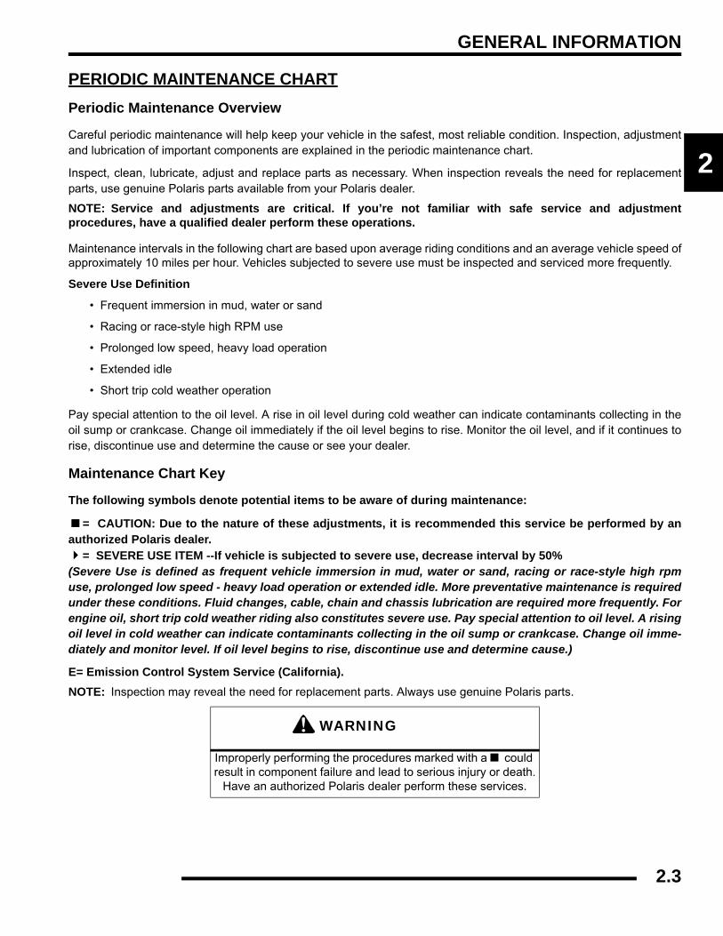
PERIODIC MAINTENANCE CHARTPeriodic Maintenance Overview
Careful periodic maintenance will help keep your vehicle in the safest, most reliable condition. Inspection, adjustmentand lubrication of important components are explained in the periodic maintenance chart.
Inspect, clean, lubricate, adjust and replace parts as necessary. When inspection reveals the need for replacementparts, use genuine Polaris parts available from your Polaris dealer.
NOTE: Service and adjustments are critical. If you’re not familiar with safe service and adjustmentprocedures, have a qualified dealer perform these operations.
Maintenance intervals in the following chart are based upon average riding conditions and an average vehicle speed ofapproximately 10 miles per hour. Vehicles subjected to severe use must be inspected and serviced more frequently.
Severe Use Definition
• Frequent immersion in mud, water or sand
• Racing or race-style high RPM use
• Prolonged low speed, heavy load operation
• Extended idle
• Short trip cold weather operation
Pay special attention to the oil level. A rise in oil level during cold weather can indicate contaminants collecting in theoil sump or crankcase. Change oil immediately if the oil level begins to rise. Monitor the oil level, and if it continues torise, discontinue use and determine the cause or see your dealer.
Maintenance Chart Key
The following symbols denote potential items to be aware of during maintenance:
= CAUTION: Due to the nature of these adjustments, it is recommended this service be performed by anauthorized Polaris dealer.
= SEVERE USE ITEM --If vehicle is subjected to severe use, decrease interval by 50% (Severe Use is defined as frequent vehicle immersion in mud, water or sand, racing or race-style high rpmuse, prolonged low speed - heavy load operation or extended idle. More preventative maintenance is requiredunder these conditions. Fluid changes, cable, chain and chassis lubrication are required more frequently. Forengine oil, short trip cold weather riding also constitutes severe use. Pay special attention to oil level. A risingoil level in cold weather can indicate contaminants collecting in the oil sump or crankcase. Change oil imme-diately and monitor level. If oil level begins to rise, discontinue use and determine cause.)
E= Emission Control System Service (California).NOTE: Inspection may reveal the need for replacement parts. Always use genuine Polaris parts.
WARNING
Improperly performing the procedures marked with a could result in component failure and lead to serious injury or death.
Have an authorized Polaris dealer perform these services.
2.3

GENERAL INFORMATION
Pre-Ride - 25 Hour Maintenance Interval
Perform these procedures more often for vehicles subjected to severe use. E Emission Control System Service (California)
Have an authorized Polaris dealer perform these services.
Item
Maintenance Interval(whichever comes first)
RemarksHours Calendar Miles
(KM)Steering - Pre-Ride -
Make adjustments as needed. See Pre-Ride Checklist on Page 2.13.
Front Suspension - Pre-Ride -
Rear Suspension - Pre-Ride -
Tires - Pre-Ride -
Brake Fluid Level - Pre-Ride -
Brake Pedal Travel - Pre-Ride -
Brake Systems - Pre-Ride -Wheels / Fasteners - Pre-Ride -Frame Fasteners - Pre-Ride -
EEngine Oil Level - Pre-Ride -
EAir Filter / Pre-Filter - Daily - Inspect;clean often
EAir Box Sediment Tube - Daily - Drain deposits when visible
Coolant Level - Daily -Check level daily, change coolant every 2 years
Head Lamp / Tail Lamp - Daily -Check operation; apply dielectric grease if replacing
EAir Filter,Main Element
- Weekly - Inspect; replace as needed
Brake Pad Wear / Inspect Parking Brake Pads
10 H Monthly - Inspect periodically
Battery 20 H Monthly - Check terminals; clean; testFront Gearcase Oil (if equipped)
25 H Monthly - Inspect level; change yearly
Middle Gearcase Oil (if equipped)
25 H Monthly - Inspect level; change yearly
Rear Gearcase Oil (if equipped)
25 H Monthly - Inspect level; change yearly
Transmission Oil 25 H Monthly - Inspect level; change yearly
EEngine Breather Filter (if equipped)
25 H Monthly - Inspect; replace if necessary
EEngine Oil Change (Break-In Period)
25 H 1 M - Perform a break-in oil change at one month
2.4
GENERAL INFORMATION
2
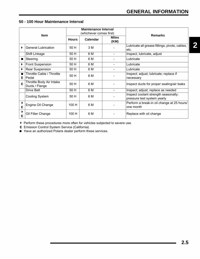
50 - 100 Hour Maintenance Interval
Perform these procedures more often for vehicles subjected to severe use. E Emission Control System Service (California)
Have an authorized Polaris dealer perform these services.
Item
Maintenance Interval (whichever comes first)
RemarksHours Calendar Miles
(KM)
General Lubrication 50 H 3 M -Lubricate all grease fittings, pivots, cables, etc.
Shift Linkage 50 H 6 M - Inspect, lubricate, adjust
Steering 50 H 6 M - Lubricate
Front Suspension 50 H 6 M - Lubricate
Rear Suspension 50 H 6 M - Lubricate
EThrottle Cable / Throttle Pedal
50 H 6 M -Inspect; adjust; lubricate; replace if necessary
E Throttle Body Air Intake Ducts / Flange
50 H 6 M - Inspect ducts for proper sealing/air leaks
Drive Belt 50 H 6 M - Inspect; adjust; replace as needed
Cooling System 50 H 6 M -Inspect coolant strength seasonally; pressure test system yearly
EEngine Oil Change 100 H 6 M -
Perform a break-in oil change at 25 hours/one month
EOil Filter Change 100 H 6 M - Replace with oil change
2.5
GENERAL INFORMATION
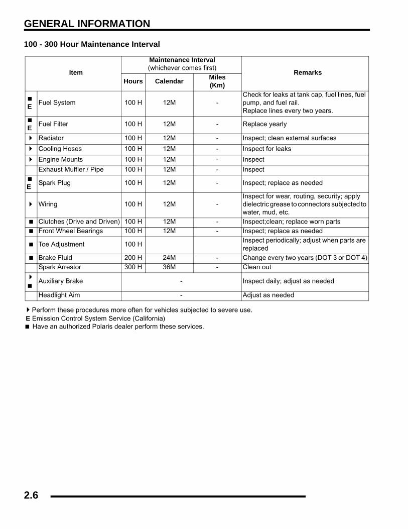
100 - 300 Hour Maintenance Interval
Perform these procedures more often for vehicles subjected to severe use. E Emission Control System Service (California)
Have an authorized Polaris dealer perform these services.
Item
Maintenance Interval (whichever comes first)
RemarksHours Calendar Miles
(Km)
E Fuel System 100 H 12M -Check for leaks at tank cap, fuel lines, fuel pump, and fuel rail. Replace lines every two years.
E Fuel Filter 100 H 12M - Replace yearly
Radiator 100 H 12M - Inspect; clean external surfaces
Cooling Hoses 100 H 12M - Inspect for leaks
Engine Mounts 100 H 12M - Inspect
Exhaust Muffler / Pipe 100 H 12M - Inspect
E Spark Plug 100 H 12M - Inspect; replace as needed
Wiring 100 H 12M -Inspect for wear, routing, security; apply dielectric grease to connectors subjected to water, mud, etc.
Clutches (Drive and Driven) 100 H 12M - Inspect;clean; replace worn partsFront Wheel Bearings 100 H 12M - Inspect; replace as needed
Toe Adjustment 100 HInspect periodically; adjust when parts are replaced
Brake Fluid 200 H 24M - Change every two years (DOT 3 or DOT 4)Spark Arrestor 300 H 36M - Clean out
Auxiliary Brake - Inspect daily; adjust as needed
Headlight Aim - Adjust as needed
2.6
GENERAL INFORMATION
2
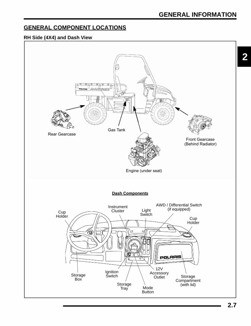
GENERAL COMPONENT LOCATIONSRH Side (4X4) and Dash View
Front Gearcase(Behind Radiator)
Engine (under seat)
Rear GearcaseGas Tank
Dash Components
CupHolder Cup
Holder
StorageCompartment
(with lid)
AWD / Differential Switch(if equipped)
12VAccessory
Outlet
ModeButton
StorageTray
IgnitionSwitchStorage
Box
LightSwitch
InstrumentCluster
2.7

GENERAL INFORMATION
LH Side and Rear View (4X4)
Battery
Front Prop Shaft
Storage
Transmission
Rear Prop Shaft
Tail Gate Latch
Air Cleaner
Muffler
2" Hitch Drive Shafts
Compartment
2.8

GENERAL INFORMATION
2
LH Side and RH Side Views (6X6)
Battery
Rear Gearcase
Mid Gearcase
Transmission
Engine (under seat)
Front Gearcase(behind radiator)
Front Prop Shaft
Rear Prop Shaft
Drive Shafts
2.9

GENERAL INFORMATION
SERVICE PRODUCTS AND LUBESPolaris Lubricants, Maintenance and Service Products
NOTE: Each item can be purchased separately atyour local Polaris dealer.
NOTE: The number count indicated by each partnumber in the table above indicates the number ofunits that are shipped with each order.
Part No. DescriptionEngine Lubricant
2870791 Fogging Oil (12 oz. Aerosol)
2871098Premium 2 Cycle Engine Oil (Quart) (12 Count)
2871281Engine Oil (Quart) Premium 4 Synthetic 0W-40 (4-Cycle) (12 Count)
2871844Engine Oil (Gallon) Premium 4 Synthetic 0W-40 (4-Cycle) (4 Count)
2871567Engine Oil (16 Gallon) Premium 4 Synthetic 0W-40 (4-Cycle)
Gearcase / Transmission Lubricants
2873602Premium Synthetic AGL Gearcase Lube(12 oz. bottle) (12 Count)
2873603Premium Synthetic AGL Gearcase Lube(1 Gal.) (4 Count)
2871653Premium ATV Angle Drive Fluid (8 oz.) (12 Count)
2872276Premium ATV Angle Drive Fluid (2.5 Gal) (2 Count)
2870465 Oil Pump for 1 Gallon Jug
2871654Premium Demand Drive Hub Fluid (8 oz.) (12 Count)
2872277Premium Demand Drive Hub Fluid (2.5 gal.) (2 Count)
Grease / Specialized Lubricants
2871322Premium All Season Grease (3 oz. cartridge) (24 Count)
2871423Premium All Season Grease (14 oz. cartridge) (10 Count)
2871460 Starter Drive Grease (12 Count)2871515 Premium U-Joint Lube (3 oz.) (24 Count)2871551 Premium U-Joint Lube (14 oz.) (10 Count)2871312 Grease Gun Kit2871329 Dielectric Grease (Nyogel™)
Coolant2871323 60/40 Coolant (Gallon) (6 Count)2871534 60/40 Coolant (Quart) (12 Count)
Part No. DescriptionAdditives / Sealants / Thread Locking Agents / Misc.
2870585 Loctite™ Primer N, Aerosol, 25 g
2871956Loctite™ Thread Sealant 565 (50 ml.) (6 Count)
2871949Loctite™ Threadlock 242 (50 ml.) (10 Count)
2871950Loctite™ Threadlock 242 (6 ml.) (12 Count)
2871951Loctite™ Threadlock 262 (50 ml.) (10 Count)
2871952Loctite™ Threadlock 262 (6 ml.) (12 Count)
2871953Loctite™ Threadlock 271 (6 ml.) (12 Count)
2871954Loctite™ Threadlock 271 (36 ml.) (6 Count)
2870584Loctite™ 680-Retaining Compound (10 ml.)
2870587Loctite™ 518 Gasket Eliminator / Flange Sealant (50 ml.) (10 Count)
2871326Premium Carbon Clean (12 oz.) (12 Count)
2870652 Fuel Stabilizer (16 oz.) (12 Count)
2871957Black RTV Silicone Sealer (3 oz. tube) (12 Count)
2871958Black RTV Silicone Sealer (11 oz. cartridge) (12 Count)
2870990 DOT 3 Brake Fluid (12 Count)2871557 Crankcase Sealant, 3-Bond 1215 (5oz.)2872893 Engine Degreaser (12oz.) (12 Count)
2.10
GENERAL INFORMATION
2
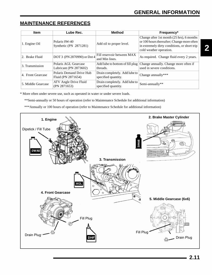
MAINTENANCE REFERENCES
* More often under severe use, such as operated in water or under severe loads.
**Semi-annually or 50 hours of operation (refer to Maintenance Schedule for additional information)
***Annually or 100 hours of operation (refer to Maintenance Schedule for additional information)
Item Lube Rec. Method Frequency*
1. Engine Oil Polaris 0W-40 Synthetic (PN 2871281) Add oil to proper level.
Change after 1st month (25 hrs), 6 months or 100 hours thereafter; Change more often in extremely dirty conditions, or short trip cold weather operation.
2. Brake Fluid DOT 3 (PN 2870990) or Dot 4 Fill reservoir between MAX and Min lines. As required. Change fluid every 2 years.
3. Transmission Polaris AGL Gearcase Lubricant (PN 2873602)
Add lube to bottom of fill plug threads.
Change annually. Change more often if used in severe conditions.
4. Front Gearcase Polaris Demand Drive Hub Fluid (PN 2871654)
Drain completely. Add lube to specified quantity. Change annually***
5. Middle Gearcase ATV Angle Drive Fluid (PN 2871653)
Drain completely. Add lube to specified quantity. Semi-annually**
2. Brake Master Cylinder1. Engine
3. Transmission
4. Front Gearcase
5. Middle Gearcase (6x6)
Dipstick / Fill Tube
Drain PlugDrain Plug
Fill Plug
Fill Plug
2.11
GENERAL INFORMATION
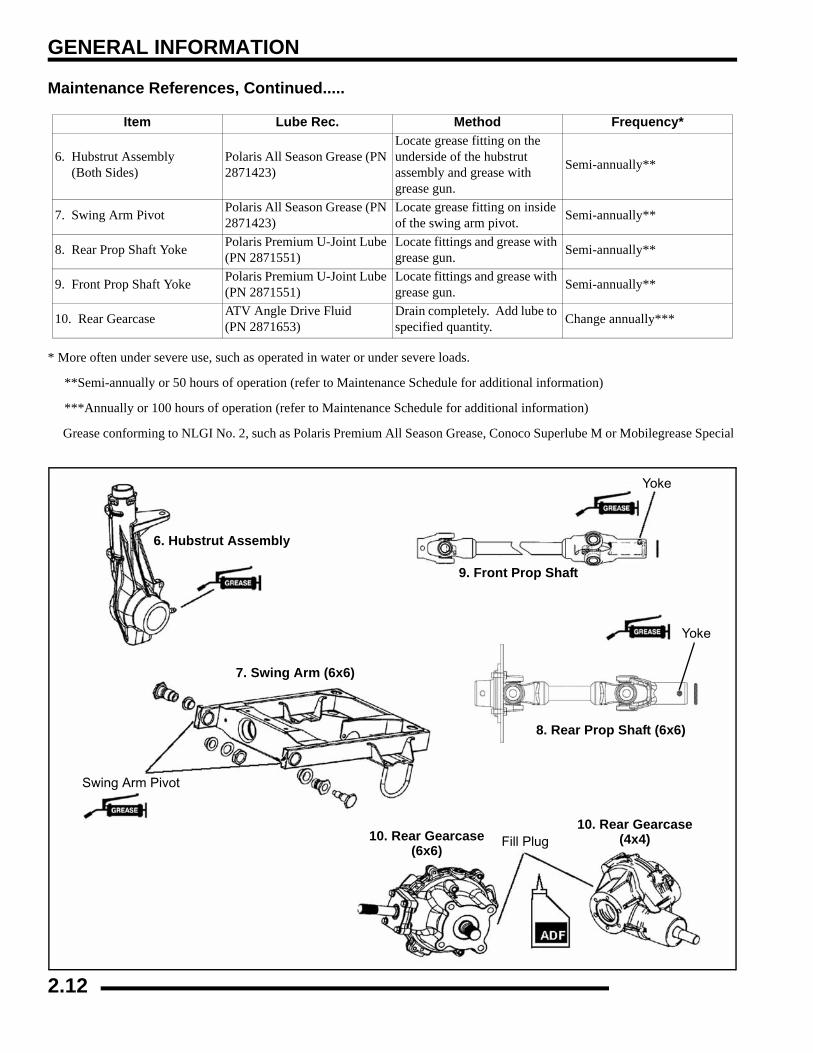
Maintenance References, Continued.....
* More often under severe use, such as operated in water or under severe loads.
**Semi-annually or 50 hours of operation (refer to Maintenance Schedule for additional information)
***Annually or 100 hours of operation (refer to Maintenance Schedule for additional information)
Grease conforming to NLGI No. 2, such as Polaris Premium All Season Grease, Conoco Superlube M or Mobilegrease Special
Item Lube Rec. Method Frequency*
6. Hubstrut Assembly (Both Sides)
Polaris All Season Grease (PN 2871423)
Locate grease fitting on the underside of the hubstrut assembly and grease with grease gun.
Semi-annually**
7. Swing Arm Pivot Polaris All Season Grease (PN 2871423)
Locate grease fitting on inside of the swing arm pivot. Semi-annually**
8. Rear Prop Shaft Yoke Polaris Premium U-Joint Lube (PN 2871551)
Locate fittings and grease with grease gun. Semi-annually**
9. Front Prop Shaft Yoke Polaris Premium U-Joint Lube (PN 2871551)
Locate fittings and grease with grease gun. Semi-annually**
10. Rear Gearcase ATV Angle Drive Fluid (PN 2871653)
Drain completely. Add lube to specified quantity. Change annually***
6. Hubstrut Assembly
7. Swing Arm (6x6)
8. Rear Prop Shaft (6x6)
9. Front Prop Shaft
10. Rear Gearcase
Yoke
Yoke
Swing Arm Pivot
Fill Plug10. Rear Gearcase(6x6)
(4x4)
2.12
GENERAL INFORMATION
2
GENERAL VEHICLE INSPECTION AND MAINTENANCEPre-Ride / Daily InspectionPerform the following pre-ride inspection daily, and whenservicing the vehicle at each scheduled maintenance.
• Tires - check condition and pressures
• Fuel and oil tanks - fill both tanks to their proper level; Do not overfill oil tank
• All brakes - check operation and adjustment (includes auxiliary brake)
• Throttle - check for free operation and closing
• Headlight/Taillight/Brakelight - check operation of all indicator lights and switches
• Engine stop switch - check for proper function
• Wheels - check for tightness of wheel nuts and axle nuts; check to be sure axle nuts are secured by cotter pins
• Air cleaner element - check for dirt; clean or replace
• Steering - check for free operation noting any unusual looseness in any area
• Loose parts - visually inspect vehicle for any damaged or loose nuts, bolts or fasteners
• Engine coolant - check for proper level at the recovery bottle
• Check all rear suspension components for wear or damage.
Frame, Nuts, Bolts, and FastenersPeriodically inspect the torque of all fasteners in accordancewith the maintenance schedule. Check that all cotter pins are inplace. Refer to specific fastener torques listed in each chapter.
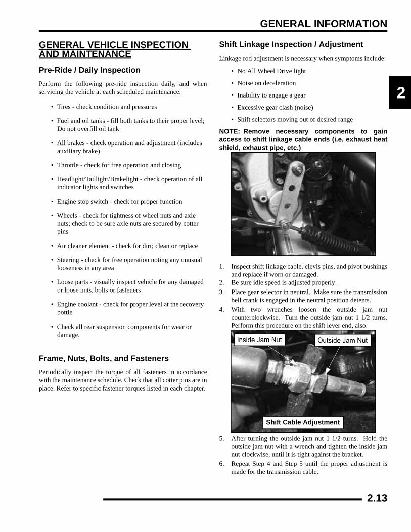
Shift Linkage Inspection / AdjustmentLinkage rod adjustment is necessary when symptoms include:
• No All Wheel Drive light
• Noise on deceleration
• Inability to engage a gear
• Excessive gear clash (noise)
• Shift selectors moving out of desired range
NOTE: Remove necessary components to gainaccess to shift linkage cable ends (i.e. exhaust heatshield, exhaust pipe, etc.)
1. Inspect shift linkage cable, clevis pins, and pivot bushingsand replace if worn or damaged.
2. Be sure idle speed is adjusted properly.3. Place gear selector in neutral. Make sure the transmission
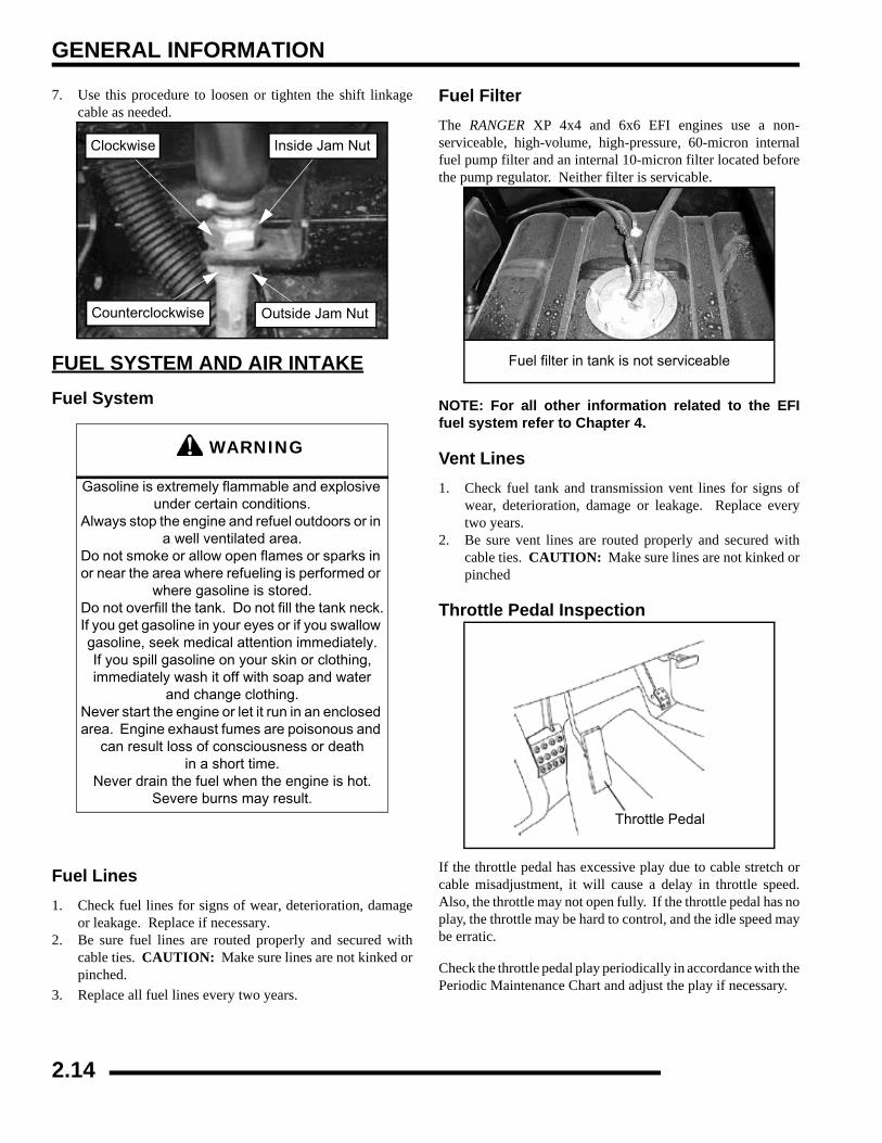
bell crank is engaged in the neutral position detents.4. With two wrenches loosen the outside jam nut
counterclockwise. Turn the outside jam nut 1 1/2 turns.Perform this procedure on the shift lever end, also.
5. After turning the outside jam nut 1 1/2 turns. Hold theoutside jam nut with a wrench and tighten the inside jamnut clockwise, until it is tight against the bracket.
6. Repeat Step 4 and Step 5 until the proper adjustment ismade for the transmission cable.
Shift Cable Adjustment
Inside Jam Nut Outside Jam Nut
2.13
GENERAL INFORMATION
7. Use this procedure to loosen or tighten the shift linkagecable as needed.
FUEL SYSTEM AND AIR INTAKEFuel System
Fuel Lines1. Check fuel lines for signs of wear, deterioration, damage
or leakage. Replace if necessary.2. Be sure fuel lines are routed properly and secured with
cable ties. CAUTION: Make sure lines are not kinked orpinched.
3. Replace all fuel lines every two years.
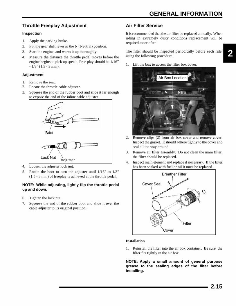
Fuel FilterThe RANGER XP 4x4 and 6x6 EFI engines use a non-serviceable, high-volume, high-pressure, 60-micron internalfuel pump filter and an internal 10-micron filter located beforethe pump regulator. Neither filter is servicable.
NOTE: For all other information related to the EFIfuel system refer to Chapter 4.
Vent Lines1. Check fuel tank and transmission vent lines for signs of
wear, deterioration, damage or leakage. Replace everytwo years.
2. Be sure vent lines are routed properly and secured withcable ties. CAUTION: Make sure lines are not kinked orpinched
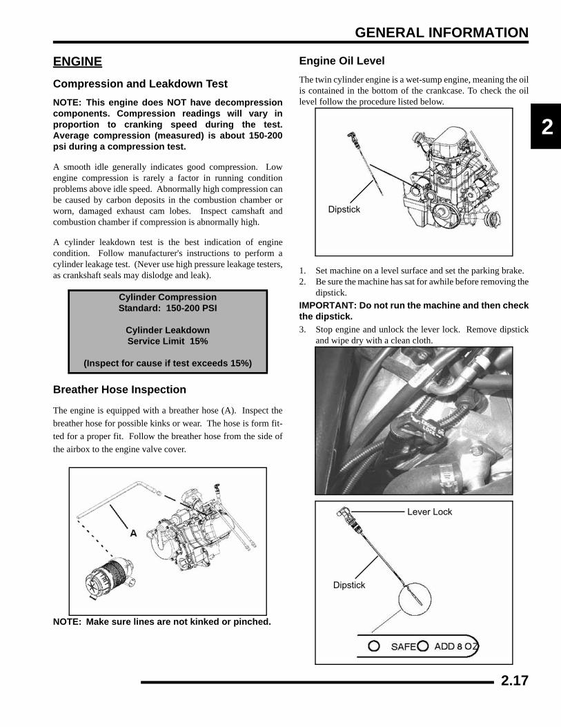
Throttle Pedal Inspection
If the throttle pedal has excessive play due to cable stretch orcable misadjustment, it will cause a delay in throttle speed.Also, the throttle may not open fully. If the throttle pedal has noplay, the throttle may be hard to control, and the idle speed maybe erratic.
Check the throttle pedal play periodically in accordance with thePeriodic Maintenance Chart and adjust the play if necessary.
WARNING
Gasoline is extremely flammable and explosive under certain conditions.
Always stop the engine and refuel outdoors or in a well ventilated area.
Do not smoke or allow open flames or sparks in or near the area where refueling is performed or
where gasoline is stored.Do not overfill the tank. Do not fill the tank neck.If you get gasoline in your eyes or if you swallow gasoline, seek medical attention immediately.If you spill gasoline on your skin or clothing, immediately wash it off with soap and water
and change clothing.Never start the engine or let it run in an enclosed area. Engine exhaust fumes are poisonous and
can result loss of consciousness or death in a short time.
Never drain the fuel when the engine is hot.Severe burns may result.
Inside Jam Nut
Outside Jam NutCounterclockwise
Clockwise
Fuel filter in tank is not serviceable
Throttle Pedal
2.14
GENERAL INFORMATION
2
Throttle Freeplay AdjustmentInspection
1. Apply the parking brake.2. Put the gear shift lever in the N (Neutral) position.3. Start the engine, and warm it up thoroughly.4. Measure the distance the throttle pedal moves before the
engine begins to pick up speed. Free play should be 1/16”- 1/8” (1.5 - 3 mm).
Adjustment
1. Remove the seat.2. Locate the throttle cable adjuster.3. Squeeze the end of the rubber boot and slide it far enough
to expose the end of the inline cable adjuster.
4. Loosen the adjuster lock nut.5. Rotate the boot to turn the adjuster until 1/16" to 1/8"
(1.5 - 3 mm) of freeplay is achieved at the throttle pedal.
NOTE: While adjusting, lightly flip the throttle pedalup and down.
6. Tighten the lock nut. 7. Squeeze the end of the rubber boot and slide it over the
cable adjuster to its original position.
Air Filter ServiceIt is recommended that the air filter be replaced annually. Whenriding in extremely dusty conditions replacement will berequired more often.
The filter should be inspected periodically before each ride,using the following procedure.
1. Lift the box to access the filter box cover.
2. Remove clips (2) from air box cover and remove cover.Inspect the gasket. It should adhere tightly to the cover andseal all the way around.
3. Remove air filter assembly. Do not clean the main filter,the filter should be replaced.
4. Inspect main element and replace if necessary. If the filterhas been soaked with fuel or oil it must be replaced.
Installation
1. Reinstall the filter into the air box container. Be sure thefilter fits tightly in the air box.
NOTE: Apply a small amount of general purposegrease to the sealing edges of the filter beforeinstalling.
Boot
AdjusterLock Nut
Air Box Location
Breather Filter
Cover Seal
Filter
Cover
2.15

GENERAL INFORMATION
2. Check air box. If oil or water deposits are found, drain theminto a suitable container.
NOTE: Service more frequently if vehicle is operatedin wet conditions or at high throttle openings forextended periods.
3. Install air box cover and secure with clips.
Air Intake Inspection1. Lift the hood.
2. Inspect the foam inserts in the air baffle boxes. If the foaminserts are dirty, clean the foam with a high flash pointsolvent, followed by hot soapy water.
3. Rinse and dry the foam thoroughly.
4. Inspect the foam for tears or damage. Replace if necessary.
5. Reinstall the foam inserts into the air baffle boxes.
Foam
Air BaffingBox
Engine Intake Duct
Air Box
PVT Intake Duct
2.16
GENERAL INFORMATION
2
ENGINECompression and Leakdown TestNOTE: This engine does NOT have decompressioncomponents. Compression readings will vary inproportion to cranking speed during the test.Average compression (measured) is about 150-200psi during a compression test.
A smooth idle generally indicates good compression. Lowengine compression is rarely a factor in running conditionproblems above idle speed. Abnormally high compression canbe caused by carbon deposits in the combustion chamber orworn, damaged exhaust cam lobes. Inspect camshaft andcombustion chamber if compression is abnormally high.
A cylinder leakdown test is the best indication of enginecondition. Follow manufacturer's instructions to perform acylinder leakage test. (Never use high pressure leakage testers,as crankshaft seals may dislodge and leak).
Breather Hose Inspection
The engine is equipped with a breather hose (A). Inspect thebreather hose for possible kinks or wear. The hose is form fit-ted for a proper fit. Follow the breather hose from the side ofthe airbox to the engine valve cover.
NOTE: Make sure lines are not kinked or pinched.
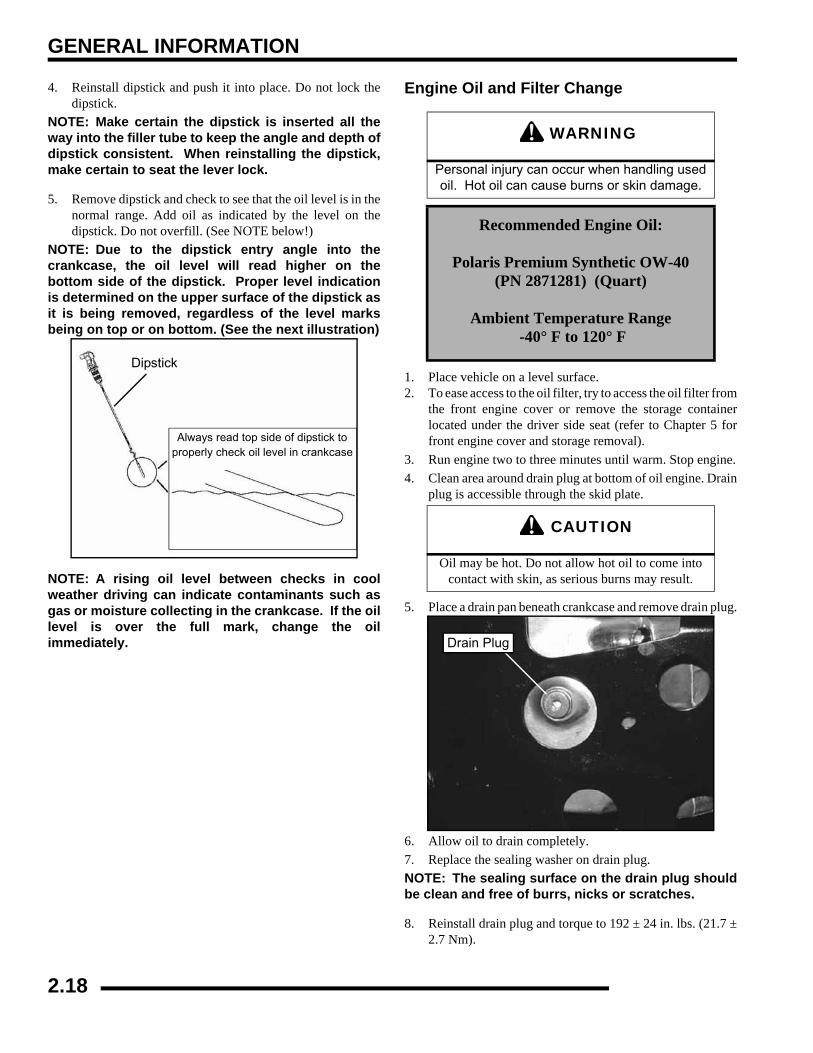
Engine Oil LevelThe twin cylinder engine is a wet-sump engine, meaning the oilis contained in the bottom of the crankcase. To check the oillevel follow the procedure listed below.
1. Set machine on a level surface and set the parking brake.2. Be sure the machine has sat for awhile before removing the
dipstick. IMPORTANT: Do not run the machine and then checkthe dipstick.3. Stop engine and unlock the lever lock. Remove dipstick
and wipe dry with a clean cloth.
Cylinder CompressionStandard: 150-200 PSI
Cylinder LeakdownService Limit 15%
(Inspect for cause if test exceeds 15%)
Dipstick
Lever Lock
Dipstick
2.17
GENERAL INFORMATION
4. Reinstall dipstick and push it into place. Do not lock thedipstick.
NOTE: Make certain the dipstick is inserted all theway into the filler tube to keep the angle and depth ofdipstick consistent. When reinstalling the dipstick,make certain to seat the lever lock.
5. Remove dipstick and check to see that the oil level is in thenormal range. Add oil as indicated by the level on thedipstick. Do not overfill. (See NOTE below!)
NOTE: Due to the dipstick entry angle into thecrankcase, the oil level will read higher on thebottom side of the dipstick. Proper level indicationis determined on the upper surface of the dipstick asit is being removed, regardless of the level marksbeing on top or on bottom. (See the next illustration)
NOTE: A rising oil level between checks in coolweather driving can indicate contaminants such asgas or moisture collecting in the crankcase. If the oillevel is over the full mark, change the oilimmediately.
Engine Oil and Filter Change
1. Place vehicle on a level surface.2. To ease access to the oil filter, try to access the oil filter from
the front engine cover or remove the storage containerlocated under the driver side seat (refer to Chapter 5 forfront engine cover and storage removal).
3. Run engine two to three minutes until warm. Stop engine.4. Clean area around drain plug at bottom of oil engine. Drain
plug is accessible through the skid plate.
5. Place a drain pan beneath crankcase and remove drain plug.
6. Allow oil to drain completely.7. Replace the sealing washer on drain plug.NOTE: The sealing surface on the drain plug shouldbe clean and free of burrs, nicks or scratches.
8. Reinstall drain plug and torque to 192 ± 24 in. lbs. (21.7 ±2.7 Nm).
Dipstick
Always read top side of dipstick toproperly check oil level in crankcase
WARNING
Personal injury can occur when handling used oil. Hot oil can cause burns or skin damage.
Recommended Engine Oil:
Polaris Premium Synthetic OW-40 (PN 2871281) (Quart)
Ambient Temperature Range -40° F to 120° F
CAUTION
Oil may be hot. Do not allow hot oil to come into contact with skin, as serious burns may result.
Drain Plug
2.18
GENERAL INFORMATION
2
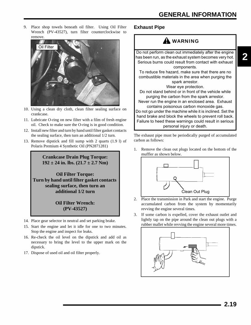
9. Place shop towels beneath oil filter. Using Oil FilterWrench (PV-43527), turn filter counterclockwise toremove.
10. Using a clean dry cloth, clean filter sealing surface oncrankcase.
11. Lubricate O-ring on new filter with a film of fresh engineoil. Check to make sure the O-ring is in good condition.
12. Install new filter and turn by hand until filter gasket contactsthe sealing surface, then turn an additional 1/2 turn.
13. Remove dipstick and fill sump with 2 quarts (1.9 l) ofPolaris Premium 4 Synthetic Oil (PN2871281)
14. Place gear selector in neutral and set parking brake.15. Start the engine and let it idle for one to two minutes.
Stop the engine and inspect for leaks.16. Re-check the oil level on the dipstick and add oil as
necessary to bring the level to the upper mark on thedipstick.
17. Dispose of used oil and oil filter properly.
Exhaust Pipe
The exhaust pipe must be periodically purged of accumulatedcarbon as follows:
1. Remove the clean out plugs located on the bottom of themuffler as shown below.
2. Place the transmission in Park and start the engine. Purgeaccumulated carbon from the system by momentarilyrevving the engine several times.
3. If some carbon is expelled, cover the exhaust outlet andlightly tap on the pipe around the clean out plugs with arubber mallet while revving the engine several more times.
Crankcase Drain Plug Torque:192 ± 24 in. lbs. (21.7 ± 2.7 Nm)
Oil Filter Torque:Turn by hand until filter gasket contacts
sealing surface, then turn an additional 1/2 turn
Oil Filter Wrench:(PV-43527)
Oil FilterWARNING
Do not perform clean out immediately after the engine has been run, as the exhaust system becomes very hot. Serious burns could result from contact with exhaust
components.To reduce fire hazard, make sure that there are no combustible materials in the area when purging the
spark arrestor.Wear eye protection.
Do not stand behind or in front of the vehicle while purging the carbon from the spark arrestor.
Never run the engine in an enclosed area. Exhaust contains poisonous carbon monoxide gas.
Do not go under the machine while it is inclined. Set the hand brake and block the wheels to prevent roll back.Failure to heed these warnings could result in serious
personal injury or death.
Clean Out Plug
2.19

GENERAL INFORMATION
4. If particles are still suspected to be in the muffler, back themachine onto an incline so the rear of the machine is onefoot higher than the front. Set the hand brake and block thewheels. Make sure the machine is in Park and repeat Steps2 and 3. SEE WARNING
5. If particles are still suspected to be in the muffler, drive themachine onto the incline so the front of the machine is onefoot higher than the rear. Set the hand brake and block thewheels. Make sure the machine is in Park and repeat Steps2 and 3. SEE WARNING
6. Repeat steps 2 through 5 until no more particles areexpelled when the engine is revved.
7. Stop the engine and allow the arrestor to cool.8. Reinstall the clean out plugs.
TRANSMISSION AND GEARCASESTransmission LubricationNOTE: It is very important to follow a regulartransmission fluid check/change schedule. Theservice manual of the RANGER recommends thelevel be checked every twenty-five (25) hours ofoperation, and changed once (1) a year.
The transmission lubricant level should be checked and changedin accordance with the maintenance schedule.
• Be sure vehicle is level with the parking brake onbefore proceeding.
• Check vent hose to be sure it is routed properly andunobstructed.
To check the level:
1. Remove the fill plug on the backside of the transmission.
2. The fluid should be at the bottom of the fill plug holethreads.
TRANSMISSION SPECIFICATIONS
Specified Lubricant:AGL Synthetic Gearcase Lubricant
(PN 2873602) (32 oz.)
Approximate Capacity at Change:15.2 oz. (450 ml.)
Drain Plug / Fill Plug Torque:14 ft. lbs. (19 Nm)
1 ft.
Fill Plug
Fill Plug Threads
Proper Fluid Level
Figure 7-26
2.20
GENERAL INFORMATION
2
To change lubricant:
1. Remove skid plate (if necessary).
2. Place a drain pan beneath the transmission oil drain plugarea.
3. Remove the drain plug and wipe the magnetic end clean toremove accumulated metallic filings.
4. After the oil has drained completely, install the drain plug.Torque to 14 ft. lbs. (19 Nm).
5. Add the proper lubricant through the fill plug hole until theoil level is at the bottom of the fill plug threads (see figure7-26). Do not overfill.
6. Torque fill plug to 14 ft. lbs. (19 Nm)
7. Check for leaks.
Front Gearcase LubricationThe gearcase lubricant level should be checked and changed inaccordance with the maintenance schedule.
• Be sure vehicle is level with parking brake on beforeproceeding.
• Check vent hose to be sure it is routed properly andunobstructed.
• The correct front gearcase lubricant to use is PolarisPremium Demand Hub Fluid.
To check the lubricant level:
The front gearcase lubricant level cannot be checked with adipstick. The gearcase must be drained and re-filled with theproper amount of lubricant or be filled to the bottom of the fillplug hole threads. Refer to procedures.
TRANSMISSION
Drain Plug14 ft. lbs.(19 Nm)
Front Gearcase Specifications
Specified Lubricant:Premium Demand Drive Hub Fluid
(PN 2871654)Capacity: 5.0 oz. (150 ml.)
Fill Plug Torque: 8-30 ft. lbs. (11-41 Nm)
Drain Plug Torque: 10 ft. lbs. (14 Nm)
Make sure vent is unobstructed
FRONT GEARCASE
Fill Plug8-30 ft. lbs.(11-41 Nm)
Drain Plug: 10 ft. lbs. (14 Nm)
2.21
GENERAL INFORMATION
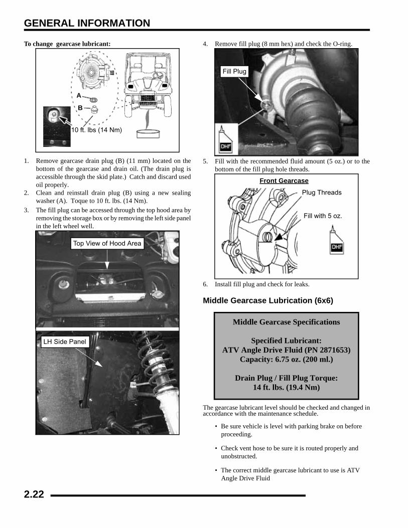
To change gearcase lubricant:
1. Remove gearcase drain plug (B) (11 mm) located on thebottom of the gearcase and drain oil. (The drain plug isaccessible through the skid plate.) Catch and discard usedoil properly.
2. Clean and reinstall drain plug (B) using a new sealingwasher (A). Toque to 10 ft. lbs. (14 Nm).
3. The fill plug can be accessed through the top hood area byremoving the storage box or by removing the left side panelin the left wheel well.
4. Remove fill plug (8 mm hex) and check the O-ring.
5. Fill with the recommended fluid amount (5 oz.) or to thebottom of the fill plug hole threads.
6. Install fill plug and check for leaks.
Middle Gearcase Lubrication (6x6)
The gearcase lubricant level should be checked and changed inaccordance with the maintenance schedule.
• Be sure vehicle is level with parking brake on before proceeding.
• Check vent hose to be sure it is routed properly and unobstructed.
• The correct middle gearcase lubricant to use is ATV Angle Drive Fluid
10 ft. lbs (14 Nm)
A
B
Top View of Hood Area
LH Side Panel
Middle Gearcase Specifications
Specified Lubricant:ATV Angle Drive Fluid (PN 2871653)
Capacity: 6.75 oz. (200 ml.)
Drain Plug / Fill Plug Torque:14 ft. lbs. (19.4 Nm)
Fill Plug
Front Gearcase
Plug Threads
Fill with 5 oz.
2.22
GENERAL INFORMATION
2
To check the lubricant level:
The gearcase must be drained and re-filled with the properamount of lubricant. Refer to the procedure below.
To change middle gearcase lubricant:
1. With the RANGER on a level surface, remove the fill plugand check the lubricant level. Lubricant should be kept atthe specified level, according to the proper gearcasespecifications listed.
2. Support the vehicle securely with a jack stand and removethe front tire on the driver’s side.
3. Remove gearcase drain plug located on the bottom of thegearcase and drain oil. (The drain plug is accessible throughthe skid plate.) Catch and discard used oil properly.
4. Clean and reinstall drain plug using a new sealing washer.5. Remove fill plug.6. Fill with the recommended fluid amount or fill to the
bottom of the threads of the fill plug hole.7. Install fill plug. Check for leaks.
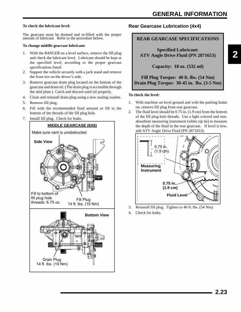
Rear Gearcase Lubrication (4x4)
To check the level:
1. With machine on level ground and with the parking brakeon, remove fill plug from rear gearcase.
2. The fluid level should be 0.75 in. (1.9 cm) from the bottomof the fill plug hole threads. Use a light colored and non-absorbent measuring instrument (white zip tie) to measurethe depth of the fluid in the rear gearcase. If level is low,add ATV Angle Drive Fluid (PN 2871653).
3. Reinstall fill plug. Tighten to 40 ft. lbs. (54 Nm).4. Check for leaks.
Make sure vent is unobstructed
Fill Plug
Drain Plug
Bottom View
Fill to bottom offill plug holethreads: 6.75 oz.
MIDDLE GEARCASE (6X6)
Side View
14 ft. lbs. (19 Nm)
14 ft. lbs. (19 Nm)
REAR GEARCASE SPECIFICATIONS
Specified Lubricant:ATV Angle Drive Fluid (PN 2871653)
Capacity: 18 oz. (532 ml)
Fill Plug Torque: 40 ft. lbs. (54 Nm)Drain Plug Torque: 30-45 in. lbs. (3-5 Nm)
MeasuringInstrument
0.75 in.(1.9 cm)
Fluid Level
0.75 in.(1.9 cm)
2.23
GENERAL INFORMATION
To change the lubricant:
1. Remove gearcase drain plug located on the bottom anddrain the oil. Catch and discard used oil properly.
2. Clean and reinstall the drain plug with a new sealing washerand tighten to 30-45 in. lbs. (3-5 Nm).
3. Remove fill plug.
4. Add 18 oz. (532 ml.) of ATV Angle Drive Fluid(PN 2871653).
5. Reinstall fill plug. Tighten to 40 ft. lbs (54 Nm).
6. Check for leaks.
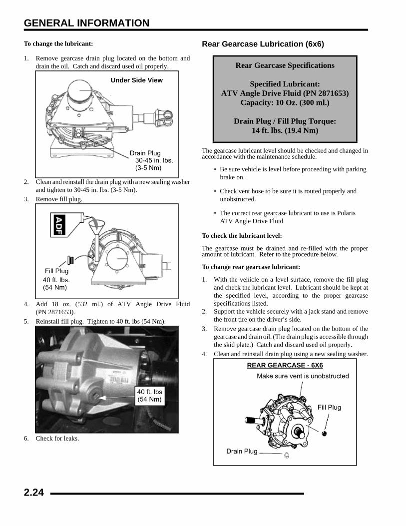
Rear Gearcase Lubrication (6x6)
The gearcase lubricant level should be checked and changed inaccordance with the maintenance schedule.
• Be sure vehicle is level before proceeding with parking brake on.
• Check vent hose to be sure it is routed properly and unobstructed.
• The correct rear gearcase lubricant to use is Polaris ATV Angle Drive Fluid
To check the lubricant level:
The gearcase must be drained and re-filled with the properamount of lubricant. Refer to the procedure below.
To change rear gearcase lubricant:
1. With the vehicle on a level surface, remove the fill plugand check the lubricant level. Lubricant should be kept atthe specified level, according to the proper gearcasespecifications listed.
2. Support the vehicle securely with a jack stand and removethe front tire on the driver’s side.
3. Remove gearcase drain plug located on the bottom of thegearcase and drain oil. (The drain plug is accessible throughthe skid plate.) Catch and discard used oil properly.
4. Clean and reinstall drain plug using a new sealing washer.
Under Side View
Drain Plug30-45 in. lbs.(3-5 Nm)
Fill Plug40 ft. lbs.(54 Nm)
40 ft. lbs(54 Nm)
Rear Gearcase Specifications
Specified Lubricant:ATV Angle Drive Fluid (PN 2871653)
Capacity: 10 Oz. (300 ml.)
Drain Plug / Fill Plug Torque:14 ft. lbs. (19.4 Nm)
Drain Plug
Fill Plug
Make sure vent is unobstructed
REAR GEARCASE - 6X6
2.24

GENERAL INFORMATION
2
5. Remove fill plug (A).
6. Fill with 10 oz. (300 ml.) or fill to the bottom of the threadsof the fill plug hole.
7. Install fill plug and torque to 14 ft. lbs (19 Nm). Check forleaks.
COOLING SYSTEMLiquid Cooling System OverviewThe engine coolant level is controlled or maintained by therecovery system. The recovery system components are therecovery bottle, radiator filler neck, radiator pressure cap andconnecting hose.
As coolant operating temperature increases, the expanding(heated) excess coolant is forced out of the radiator past thepressure cap and into the recovery bottle. As engine coolanttemperature decreases the contracting (cooled) coolant is drawnback up from the tank past the pressure cap and into the radiator.
NOTE: Some coolant level drop on new machines isnormal as the system is purging itself of trapped air.Observe coolant levels often during the break-inperiod.
Overheating of engine could occur if air is not fully purged fromsystem.
Polaris Premium 60/40 is already premixed and ready to use. Donot dilute with water.
Coolant Level InspectionThe recovery bottle, located on the left side of the machine, mustbe maintained between the minimum and maximum levelsindicated on the recovery bottle.
With the engine at operating temperature, the coolant levelshould be between the upper and lower marks on the coolantreservoir. If not:
1. Remove reservoir cap. Inner splash cap vent hole must beclear and open.
2. Fill reservoir to upper mark with Polaris Premium 60/40Anti Freeze / Coolant or 50/50 or 60/40 mixture ofantifreeze and distilled water as required for freezeprotection in your area.
3. Reinstall cap.
NOTE: If overheating is evident, allow system tocool completely and check coolant level in theradiator and inspect for signs of trapped air insystem.
A Surge Tank Cap
Surge Tank
2.25
GENERAL INFORMATION
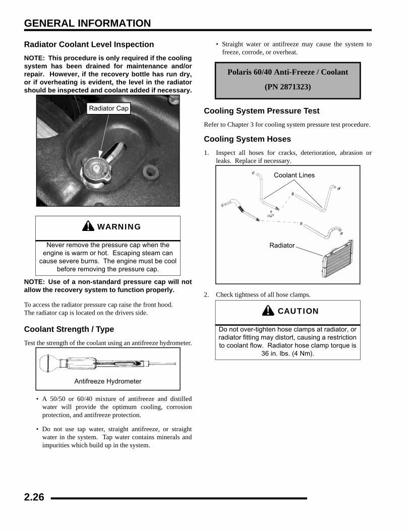
Radiator Coolant Level InspectionNOTE: This procedure is only required if the coolingsystem has been drained for maintenance and/orrepair. However, if the recovery bottle has run dry,or if overheating is evident, the level in the radiatorshould be inspected and coolant added if necessary.
NOTE: Use of a non-standard pressure cap will notallow the recovery system to function properly.
To access the radiator pressure cap raise the front hood.The radiator cap is located on the drivers side.
Coolant Strength / TypeTest the strength of the coolant using an antifreeze hydrometer.
• A 50/50 or 60/40 mixture of antifreeze and distilledwater will provide the optimum cooling, corrosionprotection, and antifreeze protection.
• Do not use tap water, straight antifreeze, or straightwater in the system. Tap water contains minerals andimpurities which build up in the system.
• Straight water or antifreeze may cause the system tofreeze, corrode, or overheat.
Cooling System Pressure TestRefer to Chapter 3 for cooling system pressure test procedure.
Cooling System Hoses1. Inspect all hoses for cracks, deterioration, abrasion or
leaks. Replace if necessary.
2. Check tightness of all hose clamps.
WARNING
Never remove the pressure cap when the engine is warm or hot. Escaping steam can
cause severe burns. The engine must be cool before removing the pressure cap.
Radiator Cap
Antifreeze Hydrometer
Polaris 60/40 Anti-Freeze / Coolant
(PN 2871323)
CAUTION
Do not over-tighten hose clamps at radiator, or radiator fitting may distort, causing a restriction to coolant flow. Radiator hose clamp torque is
36 in. lbs. (4 Nm).
Coolant Lines
Radiator
2.26
GENERAL INFORMATION
2
Radiator1. Check radiator (A) air passages for restrictions or damage.
2. Carefully straighten any bent radiator fins.3. Remove any obstructions with compressed air or low
pressure water.
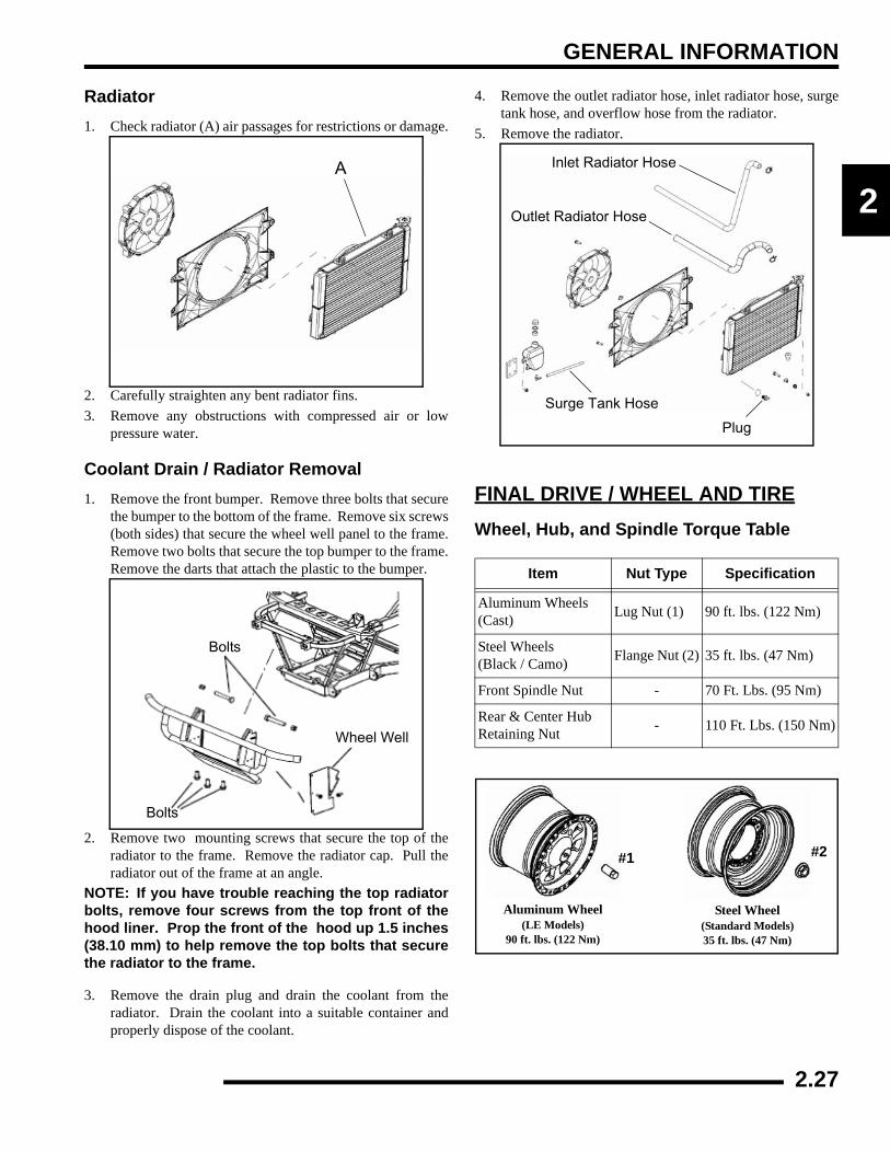
Coolant Drain / Radiator Removal1. Remove the front bumper. Remove three bolts that secure
the bumper to the bottom of the frame. Remove six screws(both sides) that secure the wheel well panel to the frame.Remove two bolts that secure the top bumper to the frame.Remove the darts that attach the plastic to the bumper.
2. Remove two mounting screws that secure the top of theradiator to the frame. Remove the radiator cap. Pull theradiator out of the frame at an angle.
NOTE: If you have trouble reaching the top radiatorbolts, remove four screws from the top front of thehood liner. Prop the front of the hood up 1.5 inches(38.10 mm) to help remove the top bolts that securethe radiator to the frame.
3. Remove the drain plug and drain the coolant from theradiator. Drain the coolant into a suitable container andproperly dispose of the coolant.
4. Remove the outlet radiator hose, inlet radiator hose, surgetank hose, and overflow hose from the radiator.
5. Remove the radiator.
FINAL DRIVE / WHEEL AND TIREWheel, Hub, and Spindle Torque Table
A
Bolts
Wheel Well
Bolts
Item Nut Type Specification
Aluminum Wheels (Cast) Lug Nut (1) 90 ft. lbs. (122 Nm)
Steel Wheels (Black / Camo) Flange Nut (2) 35 ft. lbs. (47 Nm)
Front Spindle Nut - 70 Ft. Lbs. (95 Nm)
Rear & Center Hub Retaining Nut - 110 Ft. Lbs. (150 Nm)
Inlet Radiator Hose
Surge Tank Hose
Outlet Radiator Hose
Plug
Steel Wheel(Standard Models)35 ft. lbs. (47 Nm)
Aluminum Wheel(LE Models)
90 ft. lbs. (122 Nm)
#1 #2
2.27

GENERAL INFORMATION
CV Shaft Boot InspectionInspect the CV shaft boots in the front and rear of the RANGERfor damage, tears, wear, or leaking grease. If the rubber bootexhibits any of these symptoms, replace the boot. Refer toChapter 7 for CV boot replacement, or have you Polaris dealerreplace the boot.
Wheel Removal
1. Stop the engine, place the transmission in gear and lock theparking brake.
2. Loosen the wheel nuts slightly.3. Elevate the side of the vehicle by placing a suitable stand
under the footrest frame.4. Remove the wheel nuts and washers and remove the wheel.
Wheel Installation1. With the transmission in gear and the parking brake
locked, place the wheel in the correct position on the wheelhub. Be sure the valve stem is toward the outside androtation arrows on the tire point toward forward rotation.
2. Attach the washers (if applicable) and wheel nuts and fingertighten them.
3. Lower the vehicle to the ground.
4. Securely tighten the wheel nuts to the proper torque listedin the torque table at the beginning of this section.
Tire Inspection• Improper tire inflation may affect vehicle
maneuverability.
• When replacing a tire always use original equipment size and type.
• The use of non-standard size or type tires may affect vehicle handling.
Tire Tread Depth
Always replace tires when tread depth is worn to 1/8" (3 mm) orless.
Inspect Boots
Front & Rear Wheel Nuts (4)
Front Hub Nut70 ft. lbs. (95 Nm)
Rear Hub Nut110 ft. lbs. (150 Nm)
CAUTION
If wheels are improperly installed it could affect vehicle handling and tire wear. On vehicles with tapered rear wheel nuts, make sure tapered end
of nut goes into taper on wheel.
WARNING
Operating a RANGER with worn tires will increase the possibility of the vehicle skidding
easily with possible loss of control.
Worn tires can cause an accident.
Always replace tires when the tread depth measures 1/8", (.3 cm) or less.
TreadDepth 1/8" (3 mm)
2.28
GENERAL INFORMATION
2
Tire Pressure
ELECTRICAL AND IGNITION SYSTEMBattery MaintenanceKeep battery terminals and connections free of corrosion. Ifcleaning is necessary, remove the corrosion with a stiff wirebrush. Wash with a solution of one tablespoon baking soda andone cup water. Rinse well with tap water and dry off with cleanshop towels. Coat the terminals with dielectric grease orpetroleum jelly.
Be careful not to allow cleaning solution or tap water into thebattery
NOTE: Batteries must be fully charged before use orbattery life will be reduced by 10-30% of fullpotential. Charge battery for 3-5 hours at a currentequivalent of 1/10 of the battery’s rated amp/hourcapacity. Do not use the alternator to charge a newbattery. (Refer to Battery Activation andMaintenance video PN 9917987)
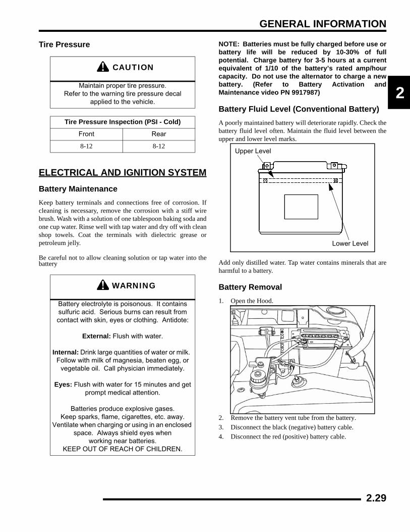
Battery Fluid Level (Conventional Battery)A poorly maintained battery will deteriorate rapidly. Check thebattery fluid level often. Maintain the fluid level between theupper and lower level marks.
Add only distilled water. Tap water contains minerals that areharmful to a battery.
Battery Removal1. Open the Hood.
2. Remove the battery vent tube from the battery.3. Disconnect the black (negative) battery cable.4. Disconnect the red (positive) battery cable.
CAUTION
Maintain proper tire pressure.Refer to the warning tire pressure decal
applied to the vehicle.
Tire Pressure Inspection (PSI - Cold)
Front Rear
8-12 8-12
WARNING
Battery electrolyte is poisonous. It contains sulfuric acid. Serious burns can result from contact with skin, eyes or clothing. Antidote:
External: Flush with water.
Internal: Drink large quantities of water or milk. Follow with milk of magnesia, beaten egg, or
vegetable oil. Call physician immediately.
Eyes: Flush with water for 15 minutes and get prompt medical attention.
Batteries produce explosive gases. Keep sparks, flame, cigarettes, etc. away.
Ventilate when charging or using in an enclosed space. Always shield eyes when
working near batteries. KEEP OUT OF REACH OF CHILDREN.
Upper Level
Lower Level
2.29
GENERAL INFORMATION
5. Lift the battery out of the vehicle, being careful not to tipit sideways and spill any electrolyte.
Battery InstallationUsing a new battery that has not been fully charged can damagethe battery and result in a shorter life. It can also hinder vehicleperformance. Follow the battery charging procedure beforeinstalling the battery.
1. Ensure that the battery is fully charged.2. Place the battery in the battery holder.3. Install the battery vent tube.NOTE: The vent tube must be free of obstructionsand securely installed. Route the tube away from theframe and vehicle body to prevent contact withelectrolyte.
4. Coat the terminals with dielectric grease or petroleum jelly.5. Connect and tighten the red (positive) cable first.6. Connect and tighten the black (negative) cable last.7. Verify that cables are properly routed.
Battery StorageWhenever the vehicle is not used for a period of three months ormore, remove the battery from the vehicle, ensure that it's fullycharged, and store it out of the sun in a cool, dry place. Checkbattery voltage each month during storage and recharge asneeded to maintain a full charge.
NOTE: Battery charge can be maintained by using aPolaris battery tender charger or by charging aboutonce a month to make up for normal self-discharge.Battery tenders can be left connected during thestorage period, and will automatically charge thebattery if the voltage drops below a pre-determinedpoint.
Battery Charging1. Remove the battery from the vehicle to prevent damage
from leaking or spilled electrolyte during charging.2. Charge the battery with a charging output no larger than
1/10 of the battery’s amp/hr rating. Charge as needed toraise the specific gravity to 1.270 or greater.
3. Reinstall the battery.
Spark Plug Service1. Remove both spark plug high tension leads (A). Clean
plug area so no dirt and debris can fall into engine whenplug is removed.
2. Remove spark plugs (B).
3. Inspect electrodes for wear and carbon buildup. Look fora sharp outer edge with no rounding or erosion of theelectrodes.
4. Clean with electrical contact cleaner or a glass bead sparkplug cleaner only. CAUTION: A wire brush or coatedabrasive should not be used.
5. Measure gap with a wire gauge. Refer to specifications inpicture below for proper spark plug type and gap. Adjustgap if necessary by bending the side electrode carefully.
6. If necessary, replace spark plug with proper type.CAUTION: Severe engine damage may occur if theincorrect spark plug is used.
7. Apply a small amount of anti-seize compound to the sparkplug threads.
CAUTION
To reduce the chance of sparks: Whenever removing the battery, disconnect the negative
(black) cable first. When reinstalling the battery, install the negative cable last.
B
A
Inspect electrode forwear and buildup
Gap - .035" (0.90 mm)
Spark Plug Gap
2.30
GENERAL INFORMATION
2
8. Install spark plug and torque to specification
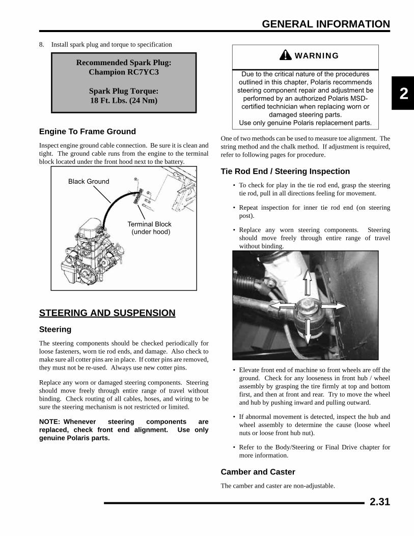
Engine To Frame GroundInspect engine ground cable connection. Be sure it is clean andtight. The ground cable runs from the engine to the terminalblock located under the front hood next to the battery.
STEERING AND SUSPENSIONSteeringThe steering components should be checked periodically forloose fasteners, worn tie rod ends, and damage. Also check tomake sure all cotter pins are in place. If cotter pins are removed,they must not be re-used. Always use new cotter pins.
Replace any worn or damaged steering components. Steeringshould move freely through entire range of travel withoutbinding. Check routing of all cables, hoses, and wiring to besure the steering mechanism is not restricted or limited.
NOTE: Whenever steering components arereplaced, check front end alignment. Use onlygenuine Polaris parts.
One of two methods can be used to measure toe alignment. Thestring method and the chalk method. If adjustment is required,refer to following pages for procedure.
Tie Rod End / Steering Inspection• To check for play in the tie rod end, grasp the steering
tie rod, pull in all directions feeling for movement.
• Repeat inspection for inner tie rod end (on steeringpost).
• Replace any worn steering components. Steeringshould move freely through entire range of travelwithout binding.
• Elevate front end of machine so front wheels are off theground. Check for any looseness in front hub / wheelassembly by grasping the tire firmly at top and bottomfirst, and then at front and rear. Try to move the wheeland hub by pushing inward and pulling outward.
• If abnormal movement is detected, inspect the hub andwheel assembly to determine the cause (loose wheelnuts or loose front hub nut).
• Refer to the Body/Steering or Final Drive chapter formore information.
Camber and CasterThe camber and caster are non-adjustable.
Recommended Spark Plug:Champion RC7YC3
Spark Plug Torque:18 Ft. Lbs. (24 Nm)
Black Ground
Terminal Block (under hood)
WARNING
Due to the critical nature of the procedures outlined in this chapter, Polaris recommends steering component repair and adjustment be
performed by an authorized Polaris MSD-certified technician when replacing worn or
damaged steering parts. Use only genuine Polaris replacement parts.
2.31
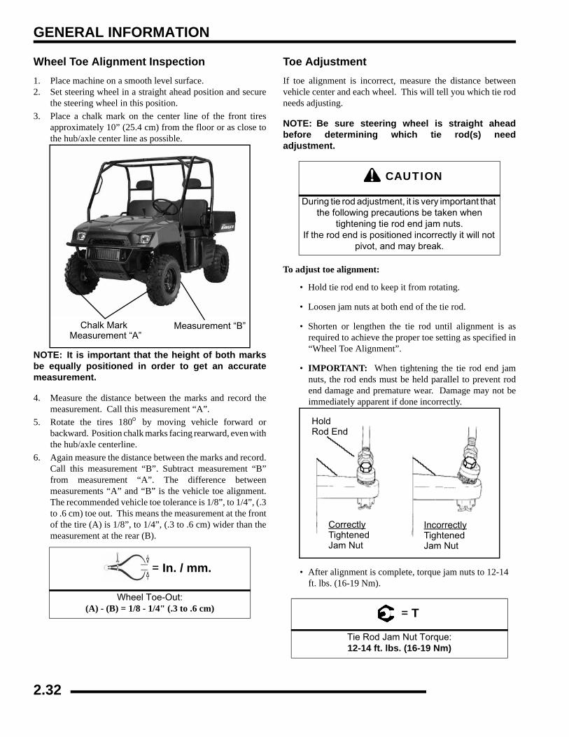
GENERAL INFORMATION
Wheel Toe Alignment Inspection1. Place machine on a smooth level surface.2. Set steering wheel in a straight ahead position and secure
the steering wheel in this position.3. Place a chalk mark on the center line of the front tires
approximately 10” (25.4 cm) from the floor or as close tothe hub/axle center line as possible.
NOTE: It is important that the height of both marksbe equally positioned in order to get an accuratemeasurement.
4. Measure the distance between the marks and record themeasurement. Call this measurement “A”.
5. Rotate the tires 180° by moving vehicle forward orbackward. Position chalk marks facing rearward, even withthe hub/axle centerline.
6. Again measure the distance between the marks and record.Call this measurement “B”. Subtract measurement “B”from measurement “A”. The difference betweenmeasurements “A” and “B” is the vehicle toe alignment.The recommended vehicle toe tolerance is 1/8”, to 1/4”, (.3to .6 cm) toe out. This means the measurement at the frontof the tire (A) is 1/8”, to 1/4”, (.3 to .6 cm) wider than themeasurement at the rear (B).
Toe AdjustmentIf toe alignment is incorrect, measure the distance betweenvehicle center and each wheel. This will tell you which tie rodneeds adjusting.
NOTE: Be sure steering wheel is straight aheadbefore determining which tie rod(s) needadjustment.
To adjust toe alignment:
• Hold tie rod end to keep it from rotating.
• Loosen jam nuts at both end of the tie rod.
• Shorten or lengthen the tie rod until alignment is asrequired to achieve the proper toe setting as specified in“Wheel Toe Alignment”.
• IMPORTANT: When tightening the tie rod end jamnuts, the rod ends must be held parallel to prevent rodend damage and premature wear. Damage may not beimmediately apparent if done incorrectly.
• After alignment is complete, torque jam nuts to 12-14 ft. lbs. (16-19 Nm).
= In. / mm.
Wheel Toe-Out:(A) - (B) = 1/8 - 1/4" (.3 to .6 cm)
Chalk Mark Measurement “A”
Measurement “B”
CAUTION
During tie rod adjustment, it is very important that the following precautions be taken when
tightening tie rod end jam nuts. If the rod end is positioned incorrectly it will not
pivot, and may break.
= T
Tie Rod Jam Nut Torque:12-14 ft. lbs. (16-19 Nm)
HoldRod End
CorrectlyTightenedJam Nut
IncorrectlyTightenedJam Nut
2.32
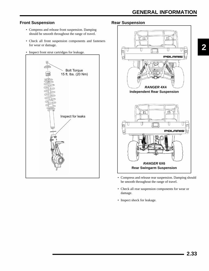
GENERAL INFORMATION
2
Front Suspension• Compress and release front suspension. Damping
should be smooth throughout the range of travel.
• Check all front suspension components and fastenersfor wear or damage.
• Inspect front strut cartridges for leakage.
Rear Suspension
• Compress and release rear suspension. Damping should be smooth throughout the range of travel.
• Check all rear suspension components for wear or damage.
• Inspect shock for leakage.
Bolt Torque
Inspect for leaks
15 ft. lbs. (20 Nm)
RANGER 4X4
RANGER 6X6
Independent Rear Suspension
Rear Swingarm Suspension
2.33
GENERAL INFORMATION
Rear Suspension Adjustment (4x4)The rear suspension may be adjusted to provide a stiffersuspension if necessary.
1. Remove the top shock mounting bolts from the insidemounting holes.
2. Reposition the shocks to the outside mounting holes.3. Reinstall the shock mounting bolts. Torque to 30 ft. lbs. (40
Nm).
Rear Spring AdjustmentThe rear shock absorber springs are adjusted by rotating theadjustment cam either clockwise or counterclockwise toincrease or decrease spring tension.
To adjust the suspension, use the adjustment cam located nearthe bottom of the rear shock. This will allow you to increase ordecrease the amount of spring preload.
BRAKE SYSTEMBrake System InspectionThe following checks are recommended to keep the brakesystem in good operating condition. Service life of brake systemcomponents depends on operating conditions. Inspect brakes inaccordance with the maintenance schedule and before each ride.
• Keep fluid level in the master cylinder reservoir to theindicated level inside reservoir.
• Use Polaris DOT 3 or DOT 4 Brake Fluid.
• Check brake system for fluid leaks.
• Check brake for excessive travel or spongy feel.
• Check friction pads for wear, damage or looseness.
• Check surface condition of the disc.
Brake Pad InspectionPads should be changed when the friction material is worn to.180" (4.6 mm). When the pad are new the thickness is .298 ±.007" (7.56 ± .178 mm).
Shock Spanner Wrench
(PN 2870872)
Outside Mounting Holes
Inside Mounting Holes
Rear SpringAdjustment Cam
Brake Pad
Service Limit - .180" (4.6 mm)
MeasureThickness
2.34
GENERAL INFORMATION
2
Parking Brake Pad InspectionMeasure the thickness of the rear caliper parking brake pads.Replace assembly as needed. See illustration below for properreadings.
Brake Hose and Fitting InspectionCheck brake system hoses and fittings for cracks, deterioration,abrasion, and leaks. Tighten any loose fittings and replace anyworn or damaged parts.
InboardPad
OutboardPad
Inboard Pad ThicknessNew .304” (7.72 mm)Limit: 0.24” (6.1 mm)
Outboard Pad ThicknessNew 0.360” (9.14 mm)Limit: 0.31” (7.87 mm)
Installed Disc to Park Brake0.375” (0.953 cm)
New Rotor Disc Thickness0.150” - 0.164”
(3.81 - 4.16 mm)
2.35

CHAPTER 3ENGINE
3
ENGINE
ENGINE SPECIFICATIONS . . . . . . . . . . . . . . . . . . . . . . . . . . . . . . . . . . . . . . . . . . . . . . . 3.2CRANKCASE EXPLODED VIEWS . . . . . . . . . . . . . . . . . . . . . . . . . . . . . . . . . . . . . . . . . 3.2ENGINE FASTENER TORQUE PATTERNS . . . . . . . . . . . . . . . . . . . . . . . . . . . . . . . . . . 3.9TORQUE SPECIFICATIONS . . . . . . . . . . . . . . . . . . . . . . . . . . . . . . . . . . . . . . . . . . . . . 3.10700 EFI ENGINE SERVICE SPECIFICATIONS. . . . . . . . . . . . . . . . . . . . . . . . . . . . . . . 3.11SPECIAL TOOLS . . . . . . . . . . . . . . . . . . . . . . . . . . . . . . . . . . . . . . . . . . . . . . . . . . . . . . 3.13
GENERAL ENGINE SERVICE . . . . . . . . . . . . . . . . . . . . . . . . . . . . . . . . . . . . . . . . . . . . 3.13ACCESSIBLE COMPONENTS. . . . . . . . . . . . . . . . . . . . . . . . . . . . . . . . . . . . . . . . . . . . 3.13PISTON IDENTIFICATION. . . . . . . . . . . . . . . . . . . . . . . . . . . . . . . . . . . . . . . . . . . . . . . 3.13COOLING SYSTEM SPECIFICATIONS. . . . . . . . . . . . . . . . . . . . . . . . . . . . . . . . . . . . . 3.13COOLING SYSTEM PRESSURE TEST. . . . . . . . . . . . . . . . . . . . . . . . . . . . . . . . . . . . . 3.14COOLING SYSTEM EXPLODED VIEW. . . . . . . . . . . . . . . . . . . . . . . . . . . . . . . . . . . . . 3.15COOLING SYSTEM BLEEDING PROCEDURE . . . . . . . . . . . . . . . . . . . . . . . . . . . . . . 3.15VALVE COVER REMOVAL - 6X6 MODELS (ENGINE INSTALLED) . . . . . . . . . . . . . . 3.17ENGINE REMOVAL . . . . . . . . . . . . . . . . . . . . . . . . . . . . . . . . . . . . . . . . . . . . . . . . . . . . 3.18ENGINE INSTALLATION NOTES . . . . . . . . . . . . . . . . . . . . . . . . . . . . . . . . . . . . . . . . . 3.19CYLINDER HONE SELECTION AND HONING PROCEDURE. . . . . . . . . . . . . . . . . . . 3.20HONING TO DEGLAZE . . . . . . . . . . . . . . . . . . . . . . . . . . . . . . . . . . . . . . . . . . . . . . . . . 3.20CLEANING THE CYLINDER AFTER HONING . . . . . . . . . . . . . . . . . . . . . . . . . . . . . . . 3.21ENGINE LUBRICATION SPECIFICATIONS . . . . . . . . . . . . . . . . . . . . . . . . . . . . . . . . . 3.21OIL PRESSURE TEST . . . . . . . . . . . . . . . . . . . . . . . . . . . . . . . . . . . . . . . . . . . . . . . . . . 3.21OIL FLOW CHART . . . . . . . . . . . . . . . . . . . . . . . . . . . . . . . . . . . . . . . . . . . . . . . . . . . . . 3.22
ENGINE DISASSEMBLY AND INSPECTION . . . . . . . . . . . . . . . . . . . . . . . . . . . . . . . . . 3.23CYLINDER HEAD ASSEMBLY EXPLODED VIEW . . . . . . . . . . . . . . . . . . . . . . . . . . . . 3.23ROCKER ARMS / PUSH RODS. . . . . . . . . . . . . . . . . . . . . . . . . . . . . . . . . . . . . . . . . . . 3.24CYLINDER HEAD REMOVAL . . . . . . . . . . . . . . . . . . . . . . . . . . . . . . . . . . . . . . . . . . . . 3.24CYLINDER HEAD INSPECTION . . . . . . . . . . . . . . . . . . . . . . . . . . . . . . . . . . . . . . . . . . 3.25CYLINDER HEAD WARP. . . . . . . . . . . . . . . . . . . . . . . . . . . . . . . . . . . . . . . . . . . . . . . . 3.25VALVE SEAL / SPRING SERVICE (ON ENGINE). . . . . . . . . . . . . . . . . . . . . . . . . . . . . 3.25CYLINDER HEAD DISASSEMBLY . . . . . . . . . . . . . . . . . . . . . . . . . . . . . . . . . . . . . . . . 3.26VALVE INSPECTION . . . . . . . . . . . . . . . . . . . . . . . . . . . . . . . . . . . . . . . . . . . . . . . . . . . 3.27COMBUSTION CHAMBER. . . . . . . . . . . . . . . . . . . . . . . . . . . . . . . . . . . . . . . . . . . . . . . 3.28VALVE SEAT RECONDITIONING . . . . . . . . . . . . . . . . . . . . . . . . . . . . . . . . . . . . . . . . . 3.28CYLINDER HEAD REASSEMBLY . . . . . . . . . . . . . . . . . . . . . . . . . . . . . . . . . . . . . . . . . 3.30VALVE SEALING TEST . . . . . . . . . . . . . . . . . . . . . . . . . . . . . . . . . . . . . . . . . . . . . . . . . 3.31CYLINDER REMOVAL . . . . . . . . . . . . . . . . . . . . . . . . . . . . . . . . . . . . . . . . . . . . . . . . . . 3.31VALVE LIFTER REMOVAL / INSPECTION . . . . . . . . . . . . . . . . . . . . . . . . . . . . . . . . . . 3.31PISTON REMOVAL . . . . . . . . . . . . . . . . . . . . . . . . . . . . . . . . . . . . . . . . . . . . . . . . . . . . 3.32CYLINDER INSPECTION. . . . . . . . . . . . . . . . . . . . . . . . . . . . . . . . . . . . . . . . . . . . . . . . 3.33PISTON-TO-CYLINDER CLEARANCE . . . . . . . . . . . . . . . . . . . . . . . . . . . . . . . . . . . . . 3.34PISTON / ROD INSPECTION. . . . . . . . . . . . . . . . . . . . . . . . . . . . . . . . . . . . . . . . . . . . . 3.34PISTON RING INSTALLED GAP . . . . . . . . . . . . . . . . . . . . . . . . . . . . . . . . . . . . . . . . . . 3.35STARTER DRIVE BENDIX REMOVAL / INSPECTION . . . . . . . . . . . . . . . . . . . . . . . . . 3.35FLYWHEEL / STATOR REMOVAL / INSPECTION . . . . . . . . . . . . . . . . . . . . . . . . . . . . 3.36ENGINE CRANKCASE DISASSEMBLY / INSPECTION . . . . . . . . . . . . . . . . . . . . . . . . 3.36CAMSHAFT INSPECTION . . . . . . . . . . . . . . . . . . . . . . . . . . . . . . . . . . . . . . . . . . . . . . . 3.44
ENGINE REASSEMBLY . . . . . . . . . . . . . . . . . . . . . . . . . . . . . . . . . . . . . . . . . . . . . . . . . 3.45CRANKCASE REASSEMBLY . . . . . . . . . . . . . . . . . . . . . . . . . . . . . . . . . . . . . . . . . . . . 3.45FLYWHEEL / STATOR INSTALLATION . . . . . . . . . . . . . . . . . . . . . . . . . . . . . . . . . . . . 3.54CYLINDER HEAD REASSEMBLY . . . . . . . . . . . . . . . . . . . . . . . . . . . . . . . . . . . . . . . . . 3.54OIL PUMP PRIMING . . . . . . . . . . . . . . . . . . . . . . . . . . . . . . . . . . . . . . . . . . . . . . . . . . . 3.57
TROUBLESHOOTING. . . . . . . . . . . . . . . . . . . . . . . . . . . . . . . . . . . . . . . . . . . . . . . . . . . 3.58ENGINE . . . . . . . . . . . . . . . . . . . . . . . . . . . . . . . . . . . . . . . . . . . . . . . . . . . . . . . . . . . . . 3.58COOLING SYSTEM . . . . . . . . . . . . . . . . . . . . . . . . . . . . . . . . . . . . . . . . . . . . . . . . . . . . 3.59
3.1
ENGINE
ENGINE SPECIFICATIONSCrankcase Exploded Views
A
B
C
D
EF
G
H IJ
KL
I
M
N
O
Apply Loctite™ 242 tobolt threads.
Apply White LithiumGrease
Apply Moly Lube Grease.
60 ± 6 in. lbs.(6.8 ± .68 Nm)
192 ± 24 in. lbs(21.7 ± 2.7 Nm)
115 ± 12 in. lbs.(13 ± 1.35 Nm)
60 ± 6 in. lbs.(6.8 ± .68 Nm)
NOTE: If needed, heatthe oil baffle bolts with aheat gun to remove.
22 ± 2 ft. lbs. (30 ± 3 Nm)
A. Journal Bearings B. CamshaftC. Thrust Plate D. Balance Shaft E. Woodruff Key F. Flange Seal G. Crankshaft H. Oil Pickup I. Journal Bearings J. Baffle K. Oil Plug L. Washer M. O-ring N. Crankcase O. Crankcase Bolts
3.2

ENGINE
3
Oil Pump / Water Pump / Engine Cover Exploded ViewA. Split GearB. Washer C. Bolt D. Oil Rotor E. Oil Pump F. Mag Gasket Cover G. Impeller H. Washer I. Nut J. Counterbalance Gear K. Washer L. Bolt M. Oil Pump Bolts N. Engine Cover O. Wire Hold down P. Stator Housing Bolts
AB
C
DE
F
GH
JK
L
M
N
P
22 ± 2 ft. lbs. (30 ± 3 Nm)
84 ± 8 in. lbs. (9.5 ± .90 Nm)
Apply corrosion resistant grease to stator grommet area. 96 ± 3 in.lbs.
(10.85 ± 0.35 Nm)
108 ± 12 in.lbs.(6.8 ± .68 Nm)
Oil Pump Bolt Tighten Sequence
Apply White LithiumGrease
Apply Polaris OW-40oil to component
Mag Cover Bolt Tighten Sequence
No Grease on this Portion of the Gasket!
I
O
3.3
ENGINE
Stator Cover / Starter / Water Pump Exploded View
A. Bolts B. Starter C. Washer D. Nut E. Positive Cable F. Negative Cable G. Gasket H. Clamp I. Bolts J. Gasket K. Water Pump Cover L. Bolts M. Crank Nut / Washer N. Flywheel
Apply Polaris Starter GreaseApply Polaris 0W-40oil to sealLoctite™ Pipe Sealant(PN 2871956)
A
1st
2nd
Tighten Top Bolt First
84 ± 8 ft.lbs. (9.5 ± 0.9 Nm)No Grease or Oil
B
C
DE
F
G
H
I
JK
L
MN
O108 ± 12 ft.lbs.(12 ± 1.35 Nm)
96 ± 12 in. lbs. (10.85 ± 1.35 Nm)
65 ± 7 ft. lbs.(88 ± 9.5 Nm)
96 ± 12 in. lbs. (10.85 ± 1.35 Nm)
Water Pump Cover Bolt Tighten Sequence
Stator Cover BoltTighten Sequence
2
1
3
4
5
6
7
3.4
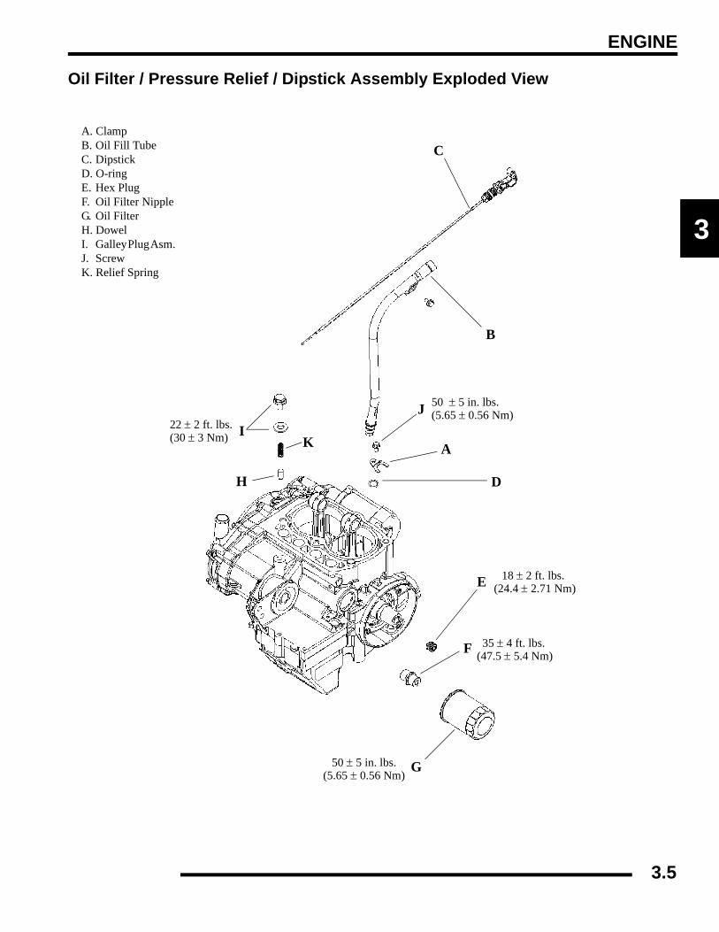
ENGINE
3
Oil Filter / Pressure Relief / Dipstick Assembly Exploded View
A. Clamp B. Oil Fill Tube C. Dipstick D. O-ring E. Hex Plug F. Oil Filter Nipple G. Oil FilterH. Dowel I. Galley Plug Asm. J. Screw K. Relief Spring
A
B
C
D
E
F
G
H
IJ
K
50 ± 5 in. lbs. (5.65 ± 0.56 Nm)
22 ± 2 ft. lbs. (30 ± 3 Nm)
18 ± 2 ft. lbs. (24.4 ± 2.71 Nm)
35 ± 4 ft. lbs. (47.5 ± 5.4 Nm)
50 ± 5 in. lbs.(5.65 ± 0.56 Nm)
3.5

ENGINE
Cylinder / Cylinder Head / Piston Exploded View
Lubricate threads & between washers and underside of bolt heads with engine oil. Torque in sequence provided.
Gasket free of oil. Verify tabs are visible.
Apply thin film of 0W- 40 to 25-55 mm of cylinder bore.
Apply 0W-40 to piston pin or pin bore.
Apply 0W- 40 to lifters.
A. Head Bolts B. Rocker Arms C. Head Assembly D. Gasket E. Pushrods F. Bushing G. Expansion Plug H. Cylinder I. Piston Assembly J. Circlip K. Gasket L. Hydraulic Lifter
A
C
D
EF
G
HI
J
KL
(Apply each Bolt Threads)
1
2
3
44
5
6
3
Circlip UP for Install
Do Not install expansion plug more than 1.5 mm inward.
Apply Polaris 0W-40 Oil
Apply Moly Lube Grease
Side View
Initial: 35 ± 4 ft. lbs (47.5 ± 5.5 Nm) in sequence. Finalize sequence by tightening an additional 90° (1/4 turn)
Head Bolt Tighten Sequence
22 ± 2 ft. lbs. (30 ± 3 Nm)
1.5 mm
B
Apply Moly Lube grease to valve tips.
3.6
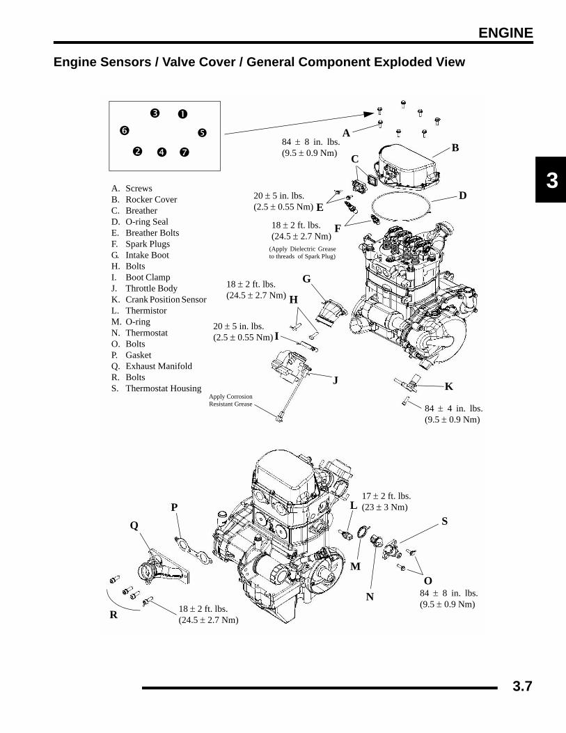
ENGINE
3
Engine Sensors / Valve Cover / General Component Exploded View
84 ± 8 in. lbs.(9.5 ± 0.9 Nm)
20 ± 5 in. lbs. (2.5 ± 0.55 Nm)
18 ± 2 ft. lbs. (24.5 ± 2.7 Nm)
20 ± 5 in. lbs. (2.5 ± 0.55 Nm)
84 ± 4 in. lbs.(9.5 ± 0.9 Nm)
17 ± 2 ft. lbs. (23 ± 3 Nm)
84 ± 8 in. lbs.(9.5 ± 0.9 Nm)
18 ± 2 ft. lbs. (24.5 ± 2.7 Nm)
A. Screws B. Rocker Cover C. Breather D. O-ring Seal E. Breather Bolts F. Spark Plugs G. Intake Boot H. Bolts I. Boot Clamp J. Throttle Body K. Crank Position Sensor L. Thermistor M. O-ring N. Thermostat O. Bolts P. Gasket Q. Exhaust Manifold R. Bolts S. Thermostat Housing
AB
E
C
D
F
G
H
I
JApply Corrosion Resistant Grease
K
L
M
NO
PQ
18 ± 2 ft. lbs. (24.5 ± 2.7 Nm)R
(Apply Dielectric Greaseto threads of Spark Plug)
S
3.7
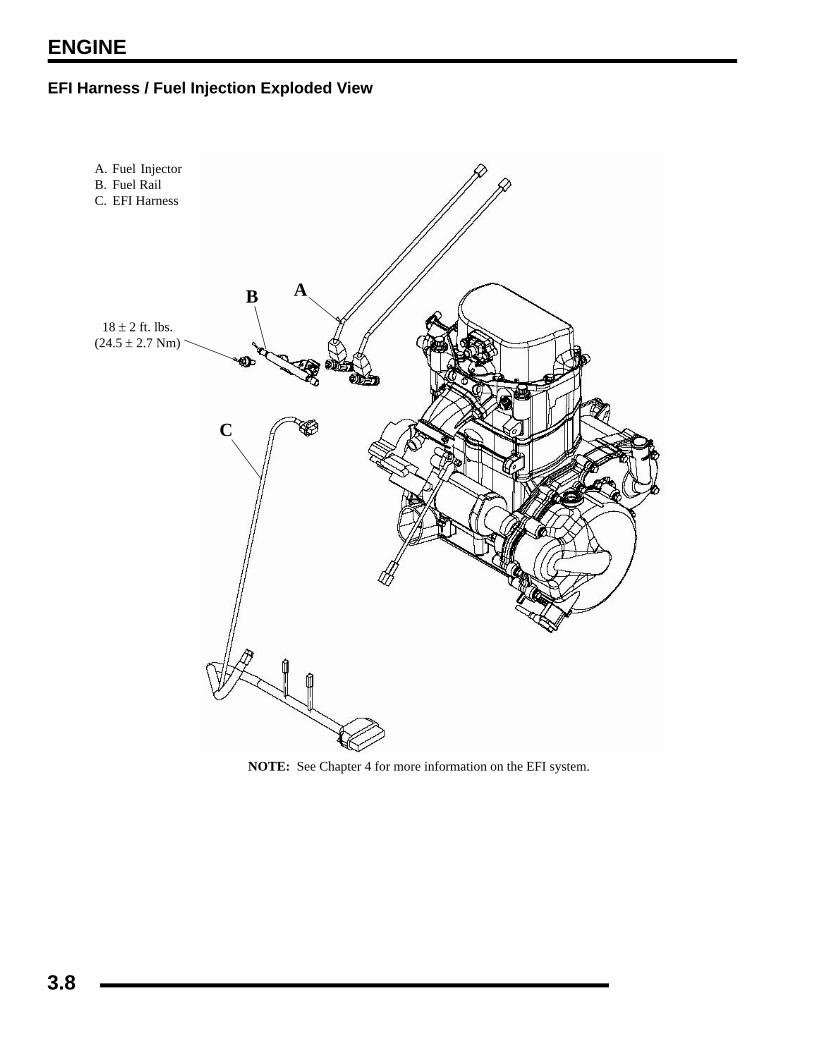
ENGINE
EFI Harness / Fuel Injection Exploded View
A. Fuel InjectorB. Fuel Rail C. EFI Harness
AB
C
18 ± 2 ft. lbs. (24.5 ± 2.7 Nm)
NOTE: See Chapter 4 for more information on the EFI system.
3.8

ENGINE
3
Engine Fastener Torque Patterns
22 ± 2 ft. lbs. (30 ± 3 Nm)
Crankcase Bolt Tighten Sequence
Lubricate threads and between washer and underside of bolt with engine oil.Torque in sequence to spec provided, allow the gasket to set for 1 minute, thentighten in sequence 90° (1/4 turn).
35 ± 4 ft. lbs. (47.5 ± 5.5 Nm) + 90° (1/4 turn)
Cylinder Head Bolt Tighten Sequence
3.9
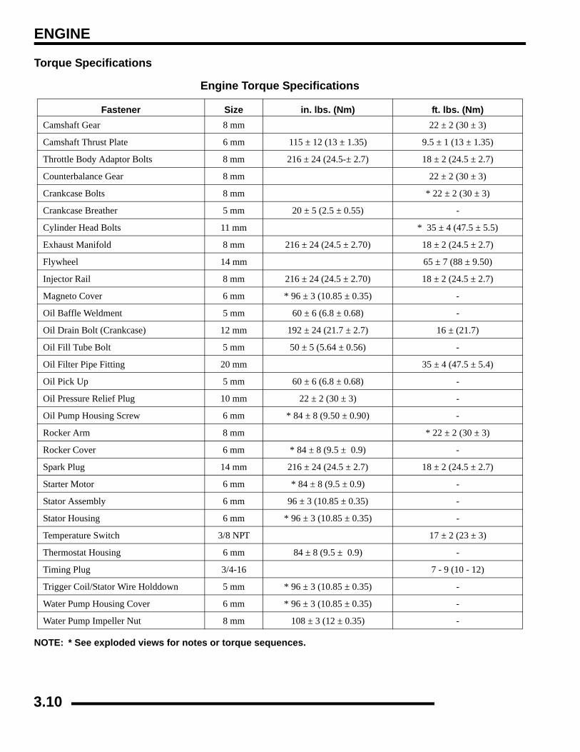
ENGINE
Torque Specifications
NOTE: * See exploded views for notes or torque sequences.
Engine Torque Specifications
Fastener Size in. lbs. (Nm) ft. lbs. (Nm)Camshaft Gear 8 mm 22 ± 2 (30 ± 3)
Camshaft Thrust Plate 6 mm 115 ± 12 (13 ± 1.35) 9.5 ± 1 (13 ± 1.35)
Throttle Body Adaptor Bolts 8 mm 216 ± 24 (24.5-± 2.7) 18 ± 2 (24.5 ± 2.7)
Counterbalance Gear 8 mm 22 ± 2 (30 ± 3)
Crankcase Bolts 8 mm * 22 ± 2 (30 ± 3)
Crankcase Breather 5 mm 20 ± 5 (2.5 ± 0.55) -
Cylinder Head Bolts 11 mm * 35 ± 4 (47.5 ± 5.5)
Exhaust Manifold 8 mm 216 ± 24 (24.5 ± 2.70) 18 ± 2 (24.5 ± 2.7)
Flywheel 14 mm 65 ± 7 (88 ± 9.50)
Injector Rail 8 mm 216 ± 24 (24.5 ± 2.70) 18 ± 2 (24.5 ± 2.7)
Magneto Cover 6 mm * 96 ± 3 (10.85 ± 0.35) -
Oil Baffle Weldment 5 mm 60 ± 6 (6.8 ± 0.68) -
Oil Drain Bolt (Crankcase) 12 mm 192 ± 24 (21.7 ± 2.7) 16 ± (21.7)
Oil Fill Tube Bolt 5 mm 50 ± 5 (5.64 ± 0.56) -
Oil Filter Pipe Fitting 20 mm 35 ± 4 (47.5 ± 5.4)
Oil Pick Up 5 mm 60 ± 6 (6.8 ± 0.68) -
Oil Pressure Relief Plug 10 mm 22 ± 2 (30 ± 3) -
Oil Pump Housing Screw 6 mm * 84 ± 8 (9.50 ± 0.90) -
Rocker Arm 8 mm * 22 ± 2 (30 ± 3)
Rocker Cover 6 mm * 84 ± 8 (9.5 ± 0.9) -
Spark Plug 14 mm 216 ± 24 (24.5 ± 2.7) 18 ± 2 (24.5 ± 2.7)
Starter Motor 6 mm * 84 ± 8 (9.5 ± 0.9) -
Stator Assembly 6 mm 96 ± 3 (10.85 ± 0.35) -
Stator Housing 6 mm * 96 ± 3 (10.85 ± 0.35) -
Temperature Switch 3/8 NPT 17 ± 2 (23 ± 3)
Thermostat Housing 6 mm 84 ± 8 (9.5 ± 0.9) -
Timing Plug 3/4-16 7 - 9 (10 - 12)
Trigger Coil/Stator Wire Holddown 5 mm * 96 ± 3 (10.85 ± 0.35) -
Water Pump Housing Cover 6 mm * 96 ± 3 (10.85 ± 0.35) -
Water Pump Impeller Nut 8 mm 108 ± 3 (12 ± 0.35) -
3.10
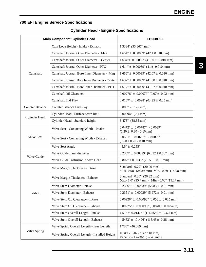
ENGINE
3
700 EFI Engine Service Specifications
Cylinder Head - Engine Specifications
Main Component: Cylinder Head EH068OLE
Camshaft
Cam Lobe Height - Intake / Exhaust 1.3334" (33.8674 mm)
Camshaft Journal Outer Diameter - Mag 1.654" ± 0.00039" (42 ± 0.010 mm)
Camshaft Journal Outer Diameter - Center 1.634"± 0.00039" (41.50 ± 0.010 mm)
Camshaft Journal Outer Diameter - PTO 1.614" ± 0.00039" (41 ± 0.010 mm)
Camshaft Journal Bore Inner Diameter - Mag 1.656" ± 0.00039" (42.07 ± 0.010 mm)
Camshaft Journal Bore Inner Diameter - Center 1.637" ± 0.00039" (41.58 ± 0.010 mm)
Camshaft Journal Bore Inner Diameter - PTO 1.617" ± 0.00039" (41.07 ± 0.010 mm)
Camshaft Oil Clearance 0.00276" ± 0.00079" (0.07 ± 0.02 mm)
Camshaft End Play 0.0167" ± 0.0098" (0.425 ± 0.25 mm)
Counter Balance Counter Balance End Play 0.005" (0.127 mm)
Cylinder HeadCylinder Head - Surface warp limit 0.00394" (0.1 mm)
Cylinder Head - Standard height 3.478" (88.35 mm)
Valve Seat
Valve Seat - Contacting Width - Intake 0.0472" ± 0.00787" - 0.0039"(1.20 ± 0.20 - 0.10mm)
Valve Seat - Contacting Width - Exhaust 0.0591" ± 0.00787" - 0.0039"(1.50 ± 0.20 - 0.10 mm)
Valve Seat Angle 45.5° ± 0.255°
Valve GuideValve Guide Inner diameter 0.2367" ± 0.00029" (6.012 ± 0.007 mm)
Valve Guide Protrusion Above Head 0.807" ± 0.0039" (20.50 ± 0.01 mm)
Valve
Valve Margin Thickness - Intake Standard: 0.79" (20.06 mm) Max- 0.98" (24.89 mm) Min.- 0.59" (14.98 mm)
Valve Margin Thickness - Exhaust Standard: 0.80" (20.32 mm) Max- 1.0" (25.4 mm) Min.- 0.60" (15.24 mm)
Valve Stem Diameter - Intake 0.2356" ± 0.00039" (5.985 ± 0.01 mm)
Valve Stem Diameter - Exhaust 0.2351" ± 0.00039" (5.972 ± 0.01 mm)
Valve Stem Oil Clearance - Intake 0.00228" ± 0.00098" (0.058 ± 0.025 mm)
Valve Stem Oil Clearance - Exhaust 0.00275" ± 0.00098" (0.0870 ± 0.025mm)
Valve Stem Overall Length - Intake 4.51" ± 0.01476" (114.5550 ± 0.375 mm)
Valve Stem Overall Length - Exhaust 4.5453" ± .01496" (115.45 ± 0.38 mm)
Valve SpringValve Spring Overall Length - Free Length 1.735" (46.069 mm)
Valve Spring Overall Length - Installed Height Intake - 1.4638" (37.18 mm) Exhaust - 1.4736" (37.43 mm)
3.11
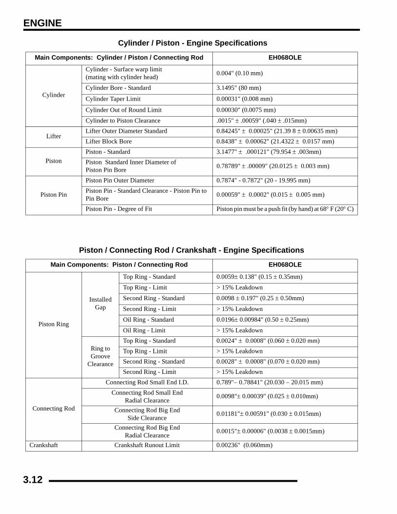
ENGINE
Cylinder / Piston - Engine Specifications
Main Components: Cylinder / Piston / Connecting Rod EH068OLE
Cylinder
Cylinder - Surface warp limit (mating with cylinder head) 0.004" (0.10 mm)
Cylinder Bore - Standard 3.1495" (80 mm)
Cylinder Taper Limit 0.00031" (0.008 mm)
Cylinder Out of Round Limit 0.00030" (0.0075 mm)
Cylinder to Piston Clearance .0015" ± .00059" (.040 ± .015mm)
LifterLifter Outer Diameter Standard 0.84245" ± 0.00025" (21.39 8 ± 0.00635 mm)Lifter Block Bore 0.8438" ± 0.00062" (21.4322 ± 0.0157 mm)
PistonPiston - Standard 3.1477" ± .000121" (79.954 ± .003mm)Piston Standard Inner Diameter of Piston Pin Bore 0.78789" ± .00009" (20.0125 ± 0.003 mm)
Piston Pin
Piston Pin Outer Diameter 0.7874" - 0.7872" (20 - 19.995 mm)Piston Pin - Standard Clearance - Piston Pin to Pin Bore 0.00059" ± 0.0002" (0.015 ± 0.005 mm)
Piston Pin - Degree of Fit Piston pin must be a push fit (by hand) at 68° F (20° C)
Piston / Connecting Rod / Crankshaft - Engine Specifications
Main Components: Piston / Connecting Rod EH068OLE
Piston Ring
InstalledGap
Top Ring - Standard 0.0059± 0.138" (0.15 ± 0.35mm)
Top Ring - Limit > 15% Leakdown
Second Ring - Standard 0.0098 ± 0.197" (0.25 ± 0.50mm)
Second Ring - Limit > 15% Leakdown
Oil Ring - Standard 0.0196± 0.00984" (0.50 ± 0.25mm)
Oil Ring - Limit > 15% Leakdown
Ring to Groove
Clearance
Top Ring - Standard 0.0024" ± 0.0008" (0.060 ± 0.020 mm)Top Ring - Limit > 15% LeakdownSecond Ring - Standard 0.0028" ± 0.0008" (0.070 ± 0.020 mm)Second Ring - Limit > 15% Leakdown
Connecting Rod
Connecting Rod Small End I.D. 0.789"− 0.78841" (20.030 − 20.015 mm)Connecting Rod Small End
Radial Clearance0.0098"± 0.00039" (0.025 ± 0.010mm)
Connecting Rod Big End Side Clearance
0.01181"± 0.00591" (0.030 ± 0.015mm)
Connecting Rod Big End Radial Clearance
0.0015"± 0.00006" (0.0038 ± 0.0015mm)
Crankshaft Crankshaft Runout Limit 0.00236" (0.060mm)
3.12
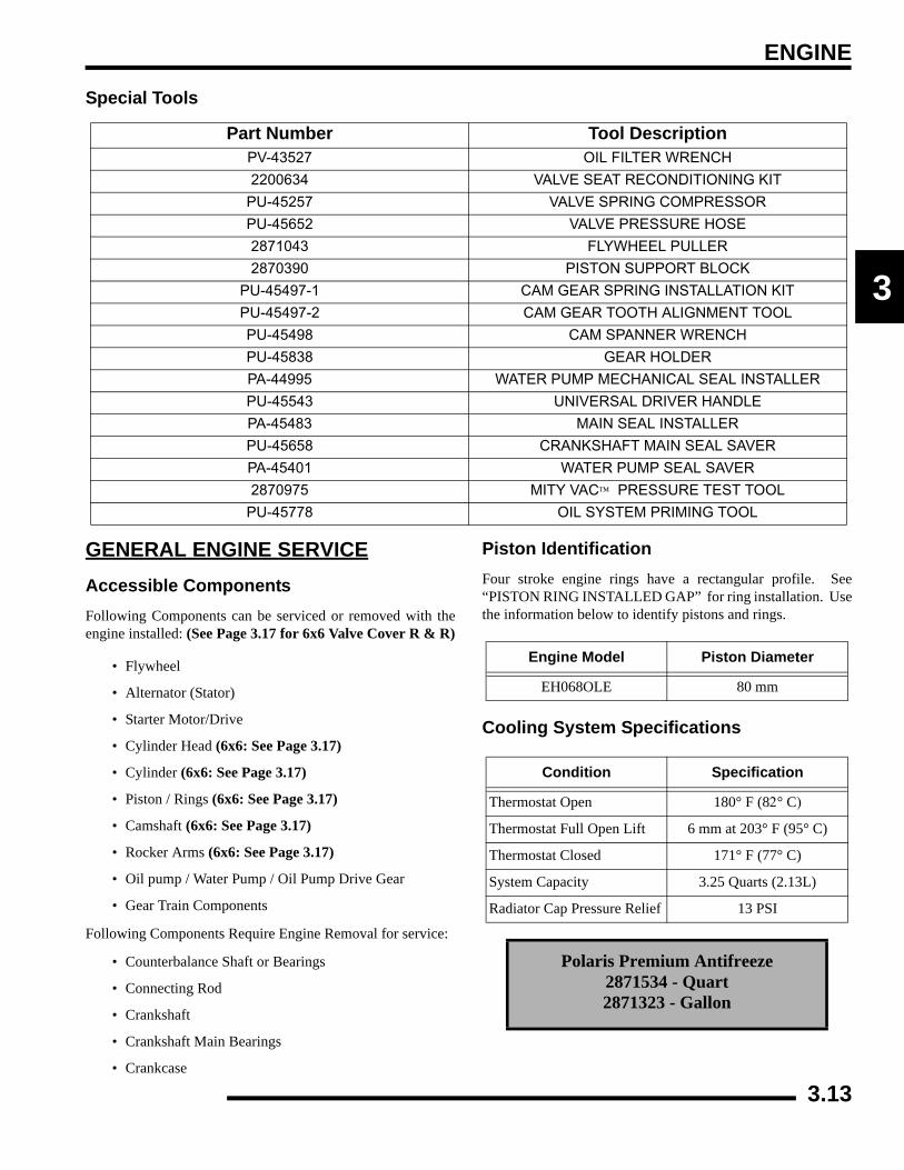
ENGINE
3
Special Tools
GENERAL ENGINE SERVICEAccessible ComponentsFollowing Components can be serviced or removed with theengine installed: (See Page 3.17 for 6x6 Valve Cover R & R)
• Flywheel
• Alternator (Stator)
• Starter Motor/Drive
• Cylinder Head (6x6: See Page 3.17)
• Cylinder (6x6: See Page 3.17)
• Piston / Rings (6x6: See Page 3.17)
• Camshaft (6x6: See Page 3.17)
• Rocker Arms (6x6: See Page 3.17)
• Oil pump / Water Pump / Oil Pump Drive Gear
• Gear Train Components
Following Components Require Engine Removal for service:
• Counterbalance Shaft or Bearings
• Connecting Rod
• Crankshaft
• Crankshaft Main Bearings
• Crankcase
Piston IdentificationFour stroke engine rings have a rectangular profile. See“PISTON RING INSTALLED GAP” for ring installation. Usethe information below to identify pistons and rings.
Cooling System Specifications
Part Number Tool DescriptionPV-43527 OIL FILTER WRENCH
2200634 VALVE SEAT RECONDITIONING KIT
PU-45257 VALVE SPRING COMPRESSOR
PU-45652 VALVE PRESSURE HOSE
2871043 FLYWHEEL PULLER
2870390 PISTON SUPPORT BLOCK
PU-45497-1 CAM GEAR SPRING INSTALLATION KIT
PU-45497-2 CAM GEAR TOOTH ALIGNMENT TOOL
PU-45498 CAM SPANNER WRENCH
PU-45838 GEAR HOLDER
PA-44995 WATER PUMP MECHANICAL SEAL INSTALLER
PU-45543 UNIVERSAL DRIVER HANDLE
PA-45483 MAIN SEAL INSTALLER
PU-45658 CRANKSHAFT MAIN SEAL SAVER
PA-45401 WATER PUMP SEAL SAVER
2870975 MITY VAC™ PRESSURE TEST TOOL
PU-45778 OIL SYSTEM PRIMING TOOL
Engine Model Piston Diameter
EH068OLE 80 mm
Condition Specification
Thermostat Open 180° F (82° C)
Thermostat Full Open Lift 6 mm at 203° F (95° C)
Thermostat Closed 171° F (77° C)
System Capacity 3.25 Quarts (2.13L)
Radiator Cap Pressure Relief 13 PSI
Polaris Premium Antifreeze2871534 - Quart2871323 - Gallon
3.13

ENGINE
Recommended Coolant
Use only high quality antifreeze/coolant mixed with distilledwater in a 50/50 or 60/40 ratio, depending on freeze protectionrequired in your area. CAUTION: Using tap water in the cooling system will lead toa buildup of deposits which may restrict coolant flow and reduceheat dissipation, resulting in possible engine damage. PolarisPremium 60/40 Antifreeze/Coolant is recommended for use inall cooling systems and comes pre-mixed, ready to use.
Cooling System Pressure Test
1. Open front hood.
2. Remove surge tank hose from coolant filler neck.
3. Connect a Mity Vac™ (PN 2870975) to the filler necknipple and pressurize system to 10 psi. The system mustretain 10 psi for five minutes or longer. If pressure loss isevident within five minutes, check the radiator, hoses,clamps and water pump seals for leakage.
Radiator Cap Pressure Test
1. Remove radiator cap and test cap using a commerciallyavailable cap tester.
2. The radiator cap relief pressure is 13 psi. Replace cap if itdoes not meet this specification.
Radiator
WaterPump
Cylinder
Thermostat
CylinderHead
WARNING
Never remove radiator cap when engine is warm or hot. The cooling system is under
pressure and serious burns may result. Allow the engine and cooling system to cool
before servicing.
Radiator Cap
Coolant Flow Diagram
To Water Pump Radiator
Surge Tank
From Thermostat Housing
3.14
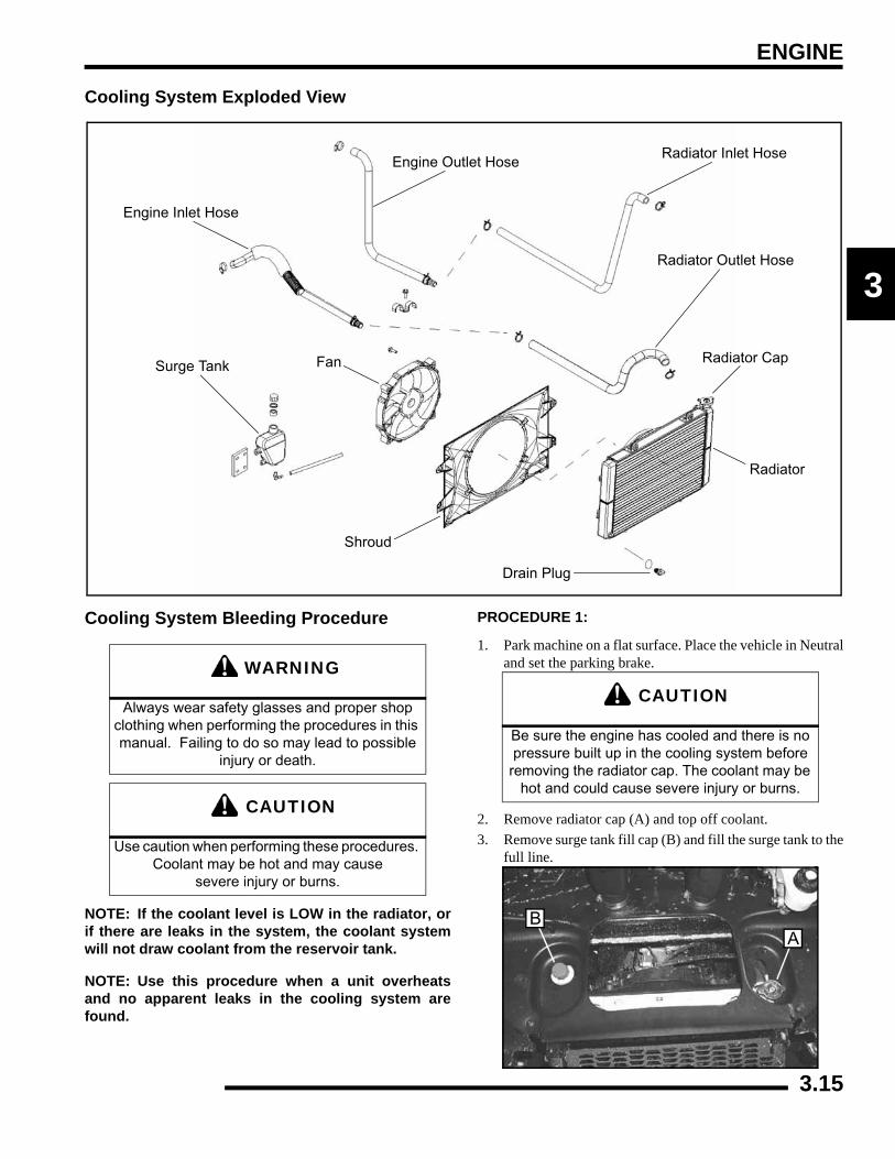
ENGINE
3
Cooling System Exploded View
Cooling System Bleeding Procedure
NOTE: If the coolant level is LOW in the radiator, orif there are leaks in the system, the coolant systemwill not draw coolant from the reservoir tank.
NOTE: Use this procedure when a unit overheatsand no apparent leaks in the cooling system arefound.
PROCEDURE 1:
1. Park machine on a flat surface. Place the vehicle in Neutraland set the parking brake.
2. Remove radiator cap (A) and top off coolant.3. Remove surge tank fill cap (B) and fill the surge tank to the
full line.
Surge Tank
Engine Inlet Hose
Engine Outlet HoseRadiator Inlet Hose
Radiator Outlet Hose
Shroud
Drain Plug
Radiator
Radiator CapFan
WARNING
Always wear safety glasses and proper shop clothing when performing the procedures in this manual. Failing to do so may lead to possible
injury or death.
CAUTION
Use caution when performing these procedures. Coolant may be hot and may cause
severe injury or burns.
CAUTION
Be sure the engine has cooled and there is no pressure built up in the cooling system before
removing the radiator cap. The coolant may be hot and could cause severe injury or burns.
AB
3.15
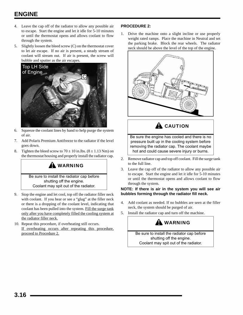
ENGINE
4. Leave the cap off of the radiator to allow any possible airto escape. Start the engine and let it idle for 5-10 minutesor until the thermostat opens and allows coolant to flowthrough the system.
5. Slightly loosen the bleed screw (C) on the thermostat coverto let air escape. If no air is present, a steady stream ofcoolant will stream out. If air is present, the screw willbubble and sputter as the air escapes.
6. Squeeze the coolant lines by hand to help purge the systemof air.
7. Add Polaris Premium Antifreeze to the radiator if the levelgoes down.
8. Tighten the bleed screw to 70 ± 10 in.lbs. (8 ± 1.13 Nm) onthe thermostat housing and properly install the radiator cap.
9. Stop the engine and let cool, top off the radiator filler neckwith coolant. If you hear or see a “glug” at the filler neckor there is a dropping of the coolant level, indicating thatcoolant has been pulled into the system. Fill the surge tankonly after you have completely filled the cooling system atthe radiator filler neck.
10. Repeat this procedure, if overheating still occurs. If overheating occurs after repeating this procedure,proceed to Procedure 2.
PROCEDURE 2:
1. Drive the machine onto a slight incline or use properlyweight rated ramps. Place the machine in Neutral and setthe parking brake. Block the rear wheels. The radiatorneck should be above the level of the top of the engine.
2. Remove radiator cap and top off coolant. Fill the surge tankto the full line.
3. Leave the cap off of the radiator to allow any possible airto escape. Start the engine and let it idle for 5-10 minutesor until the thermostat opens and allows coolant to flowthrough the system.
NOTE: If there is air in the system you will see airbubbles forming through the radiator fill neck.
4. Add coolant as needed. If no bubbles are seen at the fillerneck, the system should be purged of air.
5. Install the radiator cap and turn off the machine.
WARNING
Be sure to install the radiator cap before shutting off the engine.
Coolant may spit out of the radiator.
C
Top LH Sideof Engine
CAUTION
Be sure the engine has cooled and there is no pressure built up in the cooling system before removing the radiator cap. The coolant maybe
hot and could cause severe injury or burns.
WARNING
Be sure to install the radiator cap before shutting off the engine.
Coolant may spit out of the radiator.
3.16
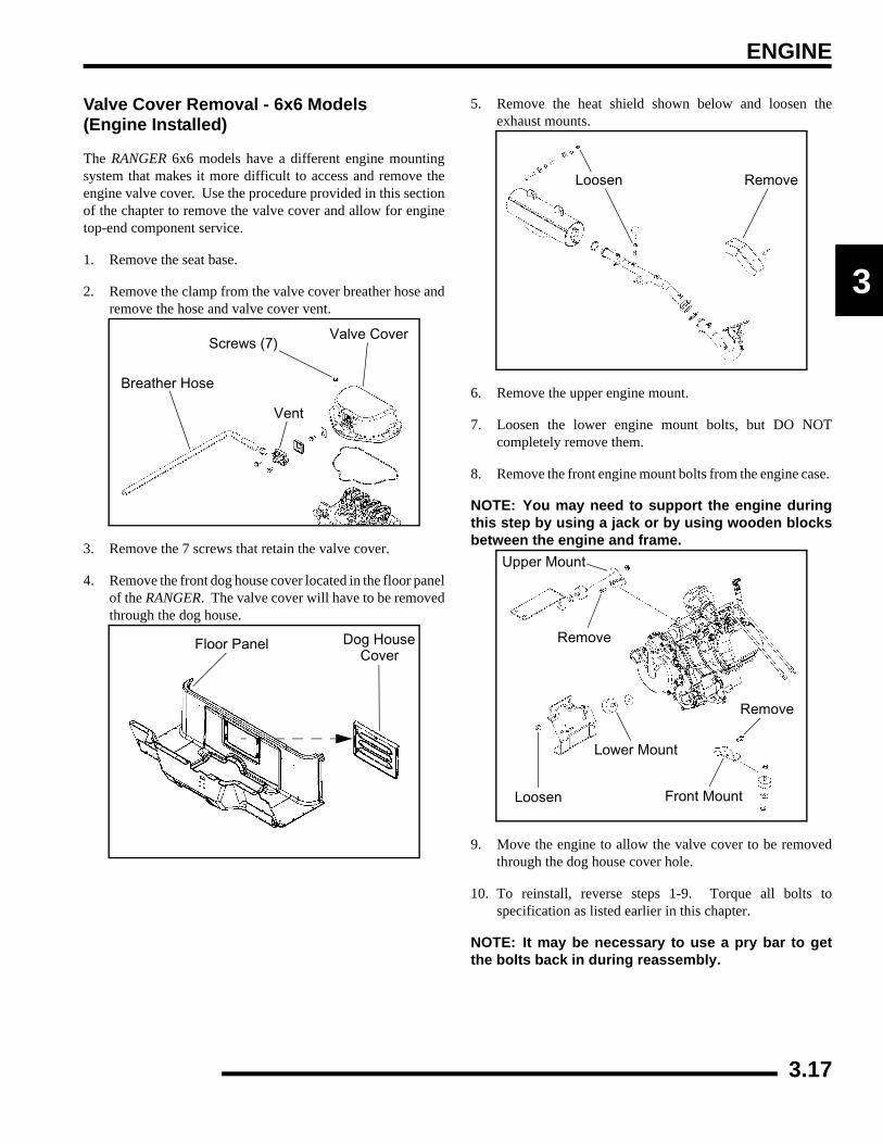
ENGINE
3
Valve Cover Removal - 6x6 Models (Engine Installed)
The RANGER 6x6 models have a different engine mountingsystem that makes it more difficult to access and remove theengine valve cover. Use the procedure provided in this sectionof the chapter to remove the valve cover and allow for enginetop-end component service.
1. Remove the seat base.
2. Remove the clamp from the valve cover breather hose andremove the hose and valve cover vent.
3. Remove the 7 screws that retain the valve cover.
4. Remove the front dog house cover located in the floor panelof the RANGER. The valve cover will have to be removedthrough the dog house.
5. Remove the heat shield shown below and loosen theexhaust mounts.
6. Remove the upper engine mount.
7. Loosen the lower engine mount bolts, but DO NOTcompletely remove them.
8. Remove the front engine mount bolts from the engine case.
NOTE: You may need to support the engine duringthis step by using a jack or by using wooden blocksbetween the engine and frame.
9. Move the engine to allow the valve cover to be removedthrough the dog house cover hole.
10. To reinstall, reverse steps 1-9. Torque all bolts tospecification as listed earlier in this chapter.
NOTE: It may be necessary to use a pry bar to getthe bolts back in during reassembly.
Breather Hose
Vent
Valve CoverScrews (7)
Floor Panel Dog HouseCover
Loosen Remove
Loosen
Remove
Remove
Upper Mount
Lower Mount
Front Mount
3.17
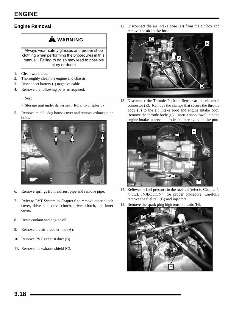
ENGINE
Engine Removal
1. Clean work area.2. Thoroughly clean the engine and chassis.3. Disconnect battery (-) negative cable.4. Remove the following parts as required:
• Seat
• Storage unit under driver seat (Refer to chapter 5)
5. Remove middle dog house cover and remove exhaust pipebolts.
6. Remove springs from exhaust pipe and remove pipe.
7. Refer to PVT System in Chapter 6 to remove outer clutchcover, drive belt, drive clutch, driven clutch, and innercover.
8. Drain coolant and engine oil.
9. Remove the air breather line (A).
10. Remove PVT exhaust duct (B).
11. Remove the exhaust shield (C).
12. Disconnect the air intake hose (D) from the air box andremove the air intake hose.
13. Disconnect the Throttle Position Sensor at the electricalconnector (E). Remove the clamps that secure the throttlebody (F) to the air intake boot and engine intake boot.Remove the throttle body (F). Insert a shop towel into theengine intake to prevent dirt from entering the intake port.
14. Relieve the fuel pressure in the fuel rail (refer to Chapter 4,“FUEL INJECTION”) for proper procedure. Carefullyremove the fuel rail (G) and injectors.
15. Remove the spark plug high tension leads (H).
WARNING
Always wear safety glasses and proper shop clothing when performing the procedures in this manual. Failing to do so may lead to possible
injury or death.
A
BC
D
E
F
G
H
3.18
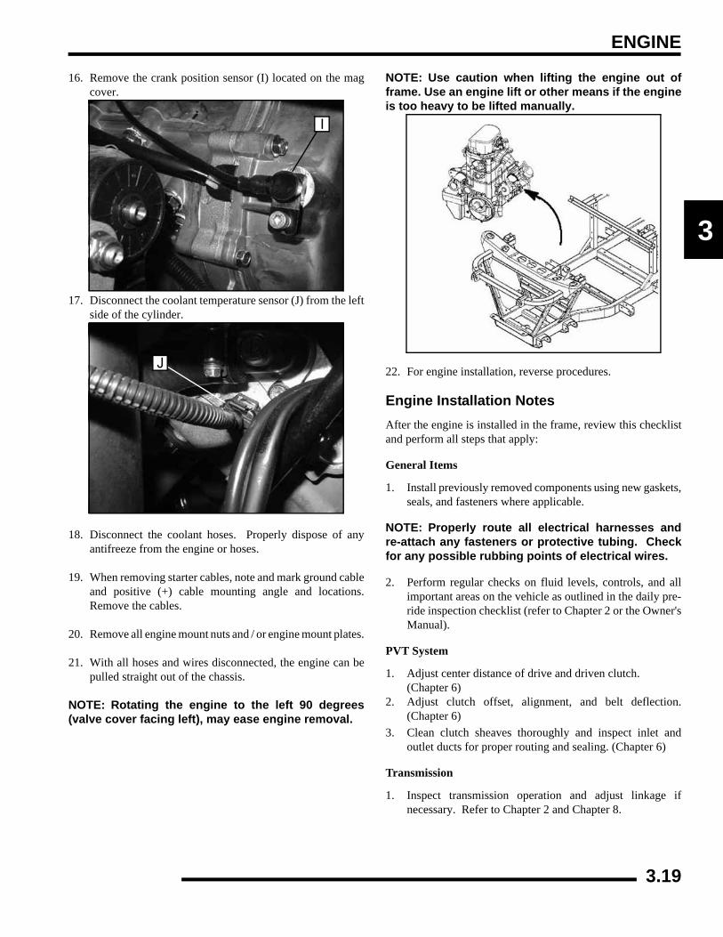
ENGINE
3
16. Remove the crank position sensor (I) located on the magcover.
17. Disconnect the coolant temperature sensor (J) from the leftside of the cylinder.
18. Disconnect the coolant hoses. Properly dispose of anyantifreeze from the engine or hoses.
19. When removing starter cables, note and mark ground cableand positive (+) cable mounting angle and locations.Remove the cables.
20. Remove all engine mount nuts and / or engine mount plates.
21. With all hoses and wires disconnected, the engine can bepulled straight out of the chassis.
NOTE: Rotating the engine to the left 90 degrees(valve cover facing left), may ease engine removal.
NOTE: Use caution when lifting the engine out offrame. Use an engine lift or other means if the engineis too heavy to be lifted manually.
22. For engine installation, reverse procedures.
Engine Installation NotesAfter the engine is installed in the frame, review this checklistand perform all steps that apply:
General Items
1. Install previously removed components using new gaskets,seals, and fasteners where applicable.
NOTE: Properly route all electrical harnesses andre-attach any fasteners or protective tubing. Checkfor any possible rubbing points of electrical wires.
2. Perform regular checks on fluid levels, controls, and allimportant areas on the vehicle as outlined in the daily pre-ride inspection checklist (refer to Chapter 2 or the Owner'sManual).
PVT System
1. Adjust center distance of drive and driven clutch. (Chapter 6)
2. Adjust clutch offset, alignment, and belt deflection.(Chapter 6)
3. Clean clutch sheaves thoroughly and inspect inlet andoutlet ducts for proper routing and sealing. (Chapter 6)
Transmission
1. Inspect transmission operation and adjust linkage ifnecessary. Refer to Chapter 2 and Chapter 8.
I
J
3.19
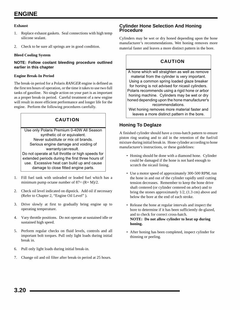
ENGINE
Exhaust
1. Replace exhaust gaskets. Seal connections with high tempsilicone sealant.
2. Check to be sure all springs are in good condition.
Bleed Cooling System
NOTE: Follow coolant bleeding procedure outlinedearlier in this chapter
Engine Break-In Period
The break-in period for a Polaris RANGER engine is defined asthe first ten hours of operation, or the time it takes to use two fulltanks of gasoline. No single action on your part is as importantas a proper break-in period. Careful treatment of a new enginewill result in more efficient performance and longer life for theengine. Perform the following procedures carefully.
1. Fill fuel tank with unleaded or leaded fuel which has aminimum pump octane number of 87= (R+ M)/2.
2. Check oil level indicated on dipstick. Add oil if necessary(Refer to Chapter 2, “Engine Oil Level” ).
3. Drive slowly at first to gradually bring engine up tooperating temperature.
4. Vary throttle positions. Do not operate at sustained idle orsustained high speed.
5. Perform regular checks on fluid levels, controls and allimportant bolt torques. Pull only light loads during initialbreak in.
6. Pull only light loads during initial break-in.
7. Change oil and oil filter after break-in period at 25 hours.
Cylinder Hone Selection And Honing ProcedureCylinders may be wet or dry honed depending upon the honemanufacturer’s recommendations. Wet honing removes morematerial faster and leaves a more distinct pattern in the bore.
Honing To DeglazeA finished cylinder should have a cross-hatch pattern to ensurepiston ring seating and to aid in the retention of the fuel/oilmixture during initial break in. Hone cylinder according to honemanufacturer's instructions, or these guidelines:
• Honing should be done with a diamond hone. Cylinder could be damaged if the hone is not hard enough to scratch the nicasil lining.
• Use a motor speed of approximately 300-500 RPM, run the hone in and out of the cylinder rapidly until cutting tension decreases. Remember to keep the hone drive shaft centered (or cylinder centered on arbor) and to bring the stones approximately 1/2, (1.3 cm) above and below the bore at the end of each stroke.
• Release the hone at regular intervals and inspect the bore to determine if it has been sufficiently de-glazed, and to check for correct cross-hatch. NOTE: Do not allow cylinder to heat up during honing.
• After honing has been completed, inspect cylinder for thinning or peeling.
CAUTION
Use only Polaris Premium 0-40W All Season synthetic oil or equivalent.
Never substitute or mix oil brands. Serious engine damage and voiding of
warranty can result. Do not operate at full throttle or high speeds for extended periods during the first three hours of use. Excessive heat can build up and cause
damage to close fitted engine parts.
CAUTION
A hone which will straighten as well as remove material from the cylinder is very important.
Using a common spring loaded glaze breaker for honing is not advised for nicasil cylinders.
Polaris recommends using a rigid hone or arbor honing machine. Cylinders may be wet or dry
honed depending upon the hone manufacturer's recommendations.
Wet honing removes more material faster and leaves a more distinct pattern in the bore.
3.20
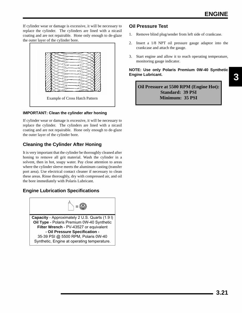
ENGINE
3
If cylinder wear or damage is excessive, it will be necessary toreplace the cylinder. The cylinders are lined with a nicasilcoating and are not repairable. Hone only enough to de-glazethe outer layer of the cylinder bore.
IMPORTANT: Clean the cylinder after honing
If cylinder wear or damage is excessive, it will be necessary toreplace the cylinder. The cylinders are lined with a nicasilcoating and are not repairable. Hone only enough to de-glazethe outer layer of the cylinder bore.
Cleaning the Cylinder After HoningIt is very important that the cylinder be thoroughly cleaned afterhoning to remove all grit material. Wash the cylinder in asolvent, then in hot, soapy water. Pay close attention to areaswhere the cylinder sleeve meets the aluminum casting (transferport area). Use electrical contact cleaner if necessary to cleanthese areas. Rinse thoroughly, dry with compressed air, and oilthe bore immediately with Polaris Lubricant.
Engine Lubrication Specifications
Oil Pressure Test1. Remove blind plug/sender from left side of crankcase.
2. Insert a 1/8 NPT oil pressure gauge adaptor into thecrankcase and attach the gauge.
3. Start engine and allow it to reach operating temperature,monitoring gauge indicator.
NOTE: Use only Polaris Premium 0W-40 SyntheticEngine Lubricant.
=
Capacity - Approximately 2 U.S. Quarts (1.9 l)Oil Type - Polaris Premium 0W-40 Synthetic
Filter Wrench - PV-43527 or equivalent- Oil Pressure Specification -
35-39 PSI @ 5500 RPM, Polaris 0W-40 Synthetic, Engine at operating temperature.
Example of Cross Hatch Pattern
Oil Pressure at 5500 RPM (Engine Hot):Standard: 39 PSIMinimum: 35 PSI
3.21
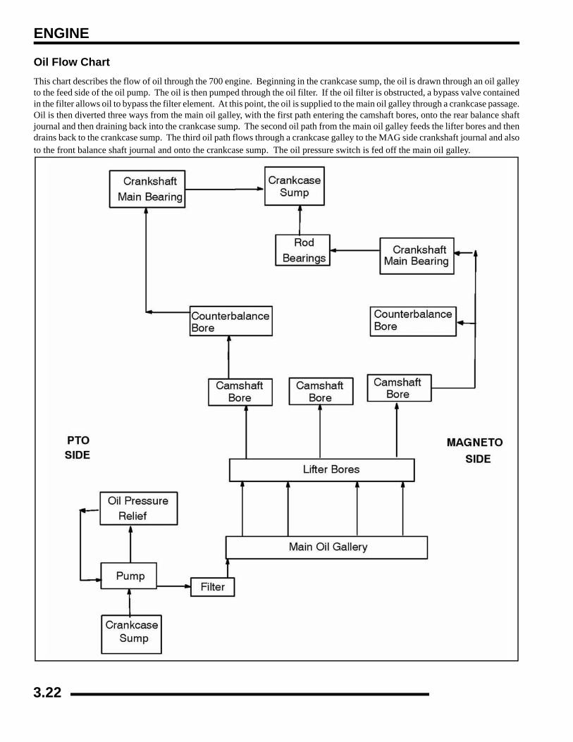
ENGINE
Oil Flow ChartThis chart describes the flow of oil through the 700 engine. Beginning in the crankcase sump, the oil is drawn through an oil galleyto the feed side of the oil pump. The oil is then pumped through the oil filter. If the oil filter is obstructed, a bypass valve containedin the filter allows oil to bypass the filter element. At this point, the oil is supplied to the main oil galley through a crankcase passage.Oil is then diverted three ways from the main oil galley, with the first path entering the camshaft bores, onto the rear balance shaftjournal and then draining back into the crankcase sump. The second oil path from the main oil galley feeds the lifter bores and thendrains back to the crankcase sump. The third oil path flows through a crankcase galley to the MAG side crankshaft journal and alsoto the front balance shaft journal and onto the crankcase sump. The oil pressure switch is fed off the main oil galley.
3.22
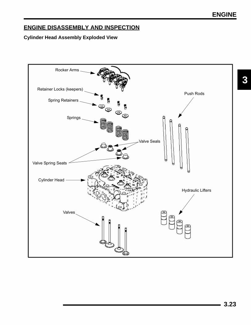
ENGINE
3
ENGINE DISASSEMBLY AND INSPECTIONCylinder Head Assembly Exploded View
Push Rods
Hydraulic Lifters
Valves
Cylinder Head
Valve Seals
Springs
Spring Retainers
Rocker Arms
Retainer Locks (keepers)
Valve Spring Seats
3.23
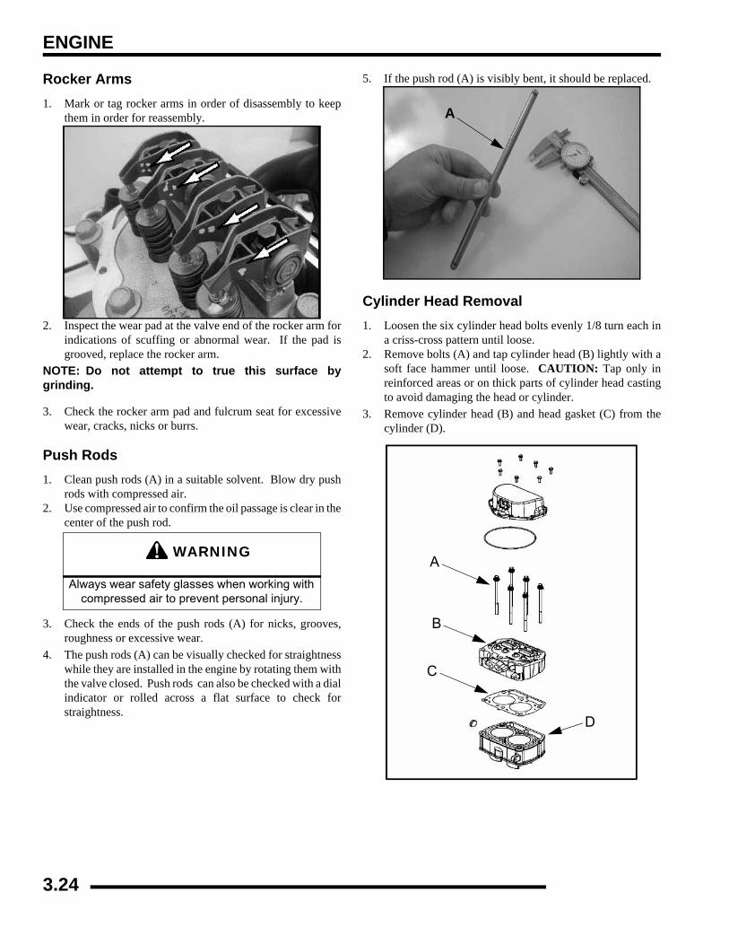
ENGINE
Rocker Arms1. Mark or tag rocker arms in order of disassembly to keep
them in order for reassembly.
2. Inspect the wear pad at the valve end of the rocker arm forindications of scuffing or abnormal wear. If the pad isgrooved, replace the rocker arm.
NOTE: Do not attempt to true this surface bygrinding.
3. Check the rocker arm pad and fulcrum seat for excessivewear, cracks, nicks or burrs.
Push Rods1. Clean push rods (A) in a suitable solvent. Blow dry push
rods with compressed air.2. Use compressed air to confirm the oil passage is clear in the
center of the push rod.
3. Check the ends of the push rods (A) for nicks, grooves,roughness or excessive wear.
4. The push rods (A) can be visually checked for straightnesswhile they are installed in the engine by rotating them withthe valve closed. Push rods can also be checked with a dialindicator or rolled across a flat surface to check forstraightness.
5. If the push rod (A) is visibly bent, it should be replaced.
Cylinder Head Removal1. Loosen the six cylinder head bolts evenly 1/8 turn each in
a criss-cross pattern until loose.2. Remove bolts (A) and tap cylinder head (B) lightly with a
soft face hammer until loose. CAUTION: Tap only inreinforced areas or on thick parts of cylinder head castingto avoid damaging the head or cylinder.
3. Remove cylinder head (B) and head gasket (C) from thecylinder (D).
WARNING
Always wear safety glasses when working with compressed air to prevent personal injury.
A
A
B
C
D
3.24
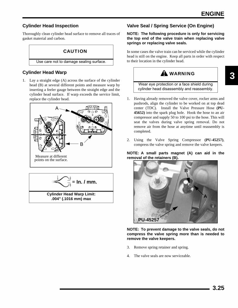
ENGINE
3
Cylinder Head InspectionThoroughly clean cylinder head surface to remove all traces ofgasket material and carbon.
Cylinder Head Warp1. Lay a straight edge (A) across the surface of the cylinder
head (B) at several different points and measure warp byinserting a feeler gauge between the straight edge and thecylinder head surface. If warp exceeds the service limit,replace the cylinder head.
Valve Seal / Spring Service (On Engine)NOTE: The following procedure is only for servicingthe top end of the valve train when replacing valvesprings or replacing valve seals.
In some cases the valve train can be serviced while the cylinderhead is still on the engine. Keep all parts in order with respectto their location in the cylinder head.
1. Having already removed the valve cover, rocker arms andpushrods, align the cylinder to be worked on at top deadcenter (TDC). Install the Valve Pressure Hose (PU-45652) into the spark plug hole. Hook the hose to an aircompressor and supply 50 to 100 psi to the hose. This willseat the valves during valve spring removal. Do notremove air from the hose at anytime until reassembly iscompleted.
2. Using the Valve Spring Compressor (PU-45257),compress the valve spring and remove the valve keepers.
NOTE: A small parts magnet (A) can aid in theremoval of the retainers (B).
NOTE: To prevent damage to the valve seals, do notcompress the valve spring more than is needed toremove the valve keepers.
3. Remove spring retainer and spring.
4. The valve seals are now serviceable.
CAUTION
Use care not to damage sealing surface.
= In. / mm.
Cylinder Head Warp Limit: .004" (.1016 mm) max
A
B
Measure at different points on the surface.
WARNING
Wear eye protection or a face shield during cylinder head disassembly and reassembly.
A
B
PU-45257
3.25

ENGINE
Cylinder Head Disassembly1. Carefully remove the cylinder components.
2. Place the hydraulic lifters (C), pushrods (D), and rockerarms (E) in a safe, clean area.
3. Measure free length of spring with a Vernier caliper.Compare to specifications. Replace spring if measurementis out of specification.
4. Remove valve guide seals.
IMPORTANT: It is recommended to replace sealswhenever the cylinder head is disassembled.Hardened, cracked or worn valve seals will causeexcessive oil consumption and carbon buildup.
5. Mark the valves with a white pen. Remove the valves fromthe cylinder head. This will ensure that the valves areproperly placed during engine reassembly.
= In. / mm.
Valve Spring Free Length: Std: 1.735" (44.069 mm)
DC
E
Valve Spring Free Length
Mark the Valves
3.26

ENGINE
3
Valve Inspection1. Remove all carbon from valves with a soft wire wheel or
brush.2. Check valve face for runout, pitting, and burnt spots. To
check for bent valve stems, mount valve in a drill or use “V”blocks and a dial indicator.
3. Check end of valve stem for flaring, pitting, wear or damage(A).
4. Inspect split keeper groove for wear or flaring of the keeperseat area (B).
NOTE: The valves can be re-faced or end ground, ifnecessary. They must be replaced if extensivelyworn, burnt, bent, or damaged.
5. Measure diameter of valve stem with a micrometer in threeplaces, then rotate 90 degrees and measure again (sixmeasurements total). Compare to specifications.
6. Measure valve guide (C) inside diameter at the top middleand end of the guide using a small hole gauge and amicrometer. Measure in two directions.
7. Subtract valve stem measurement from the valve guidemeasurement to obtain stem to guide clearance. NOTE:The valve guides cannot be replaced. Be sure to measureeach guide and valve combination individually.
A
B
Measure valve stem in several places.Rotate the valve 90 degrees and measurefor wear.
= In. / mm.
Valve Stem Diameter: Intake: 0.2356" + 0.00039"
(5.985 + 0.01 mm) Exhaust: 0.2351" + 0.00039"
(5.972 + 0.01 mm)
= In. / mm.
Valve Guide I.D.: 0.23672" + 0.000295"(6.0617 + 0.0075 mm)
C
3.27
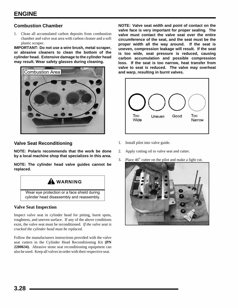
ENGINE
Combustion Chamber1. Clean all accumulated carbon deposits from combustion
chamber and valve seat area with carbon cleaner and a softplastic scraper.
IMPORTANT: Do not use a wire brush, metal scraper,or abrasive cleaners to clean the bottom of thecylinder head. Extensive damage to the cylinder headmay result. Wear safety glasses during cleaning.
Valve Seat ReconditioningNOTE: Polaris recommends that the work be doneby a local machine shop that specializes in this area.
NOTE: The cylinder head valve guides cannot bereplaced.
Valve Seat InspectionInspect valve seat in cylinder head for pitting, burnt spots,roughness, and uneven surface. If any of the above conditionsexist, the valve seat must be reconditioned. If the valve seat iscracked the cylinder head must be replaced.
Follow the manufacturers instructions provided with the valveseat cutters in the Cylinder Head Reconditioning Kit (PN2200634). Abrasive stone seat reconditioning equipment canalso be used. Keep all valves in order with their respective seat.
NOTE: Valve seat width and point of contact on thevalve face is very important for proper sealing. Thevalve must contact the valve seat over the entirecircumference of the seat, and the seat must be theproper width all the way around. If the seat isuneven, compression leakage will result. If the seatis too wide, seat pressure is reduced, causingcarbon accumulation and possible compressionloss. If the seat is too narrow, heat transfer fromvalve to seat is reduced. The valve may overheatand warp, resulting in burnt valves.
1. Install pilot into valve guide.
2. Apply cutting oil to valve seat and cutter.
3. Place 46° cutter on the pilot and make a light cut.
WARNING
Wear eye protection or a face shield during cylinder head disassembly and reassembly.
Combustion Area
3.28
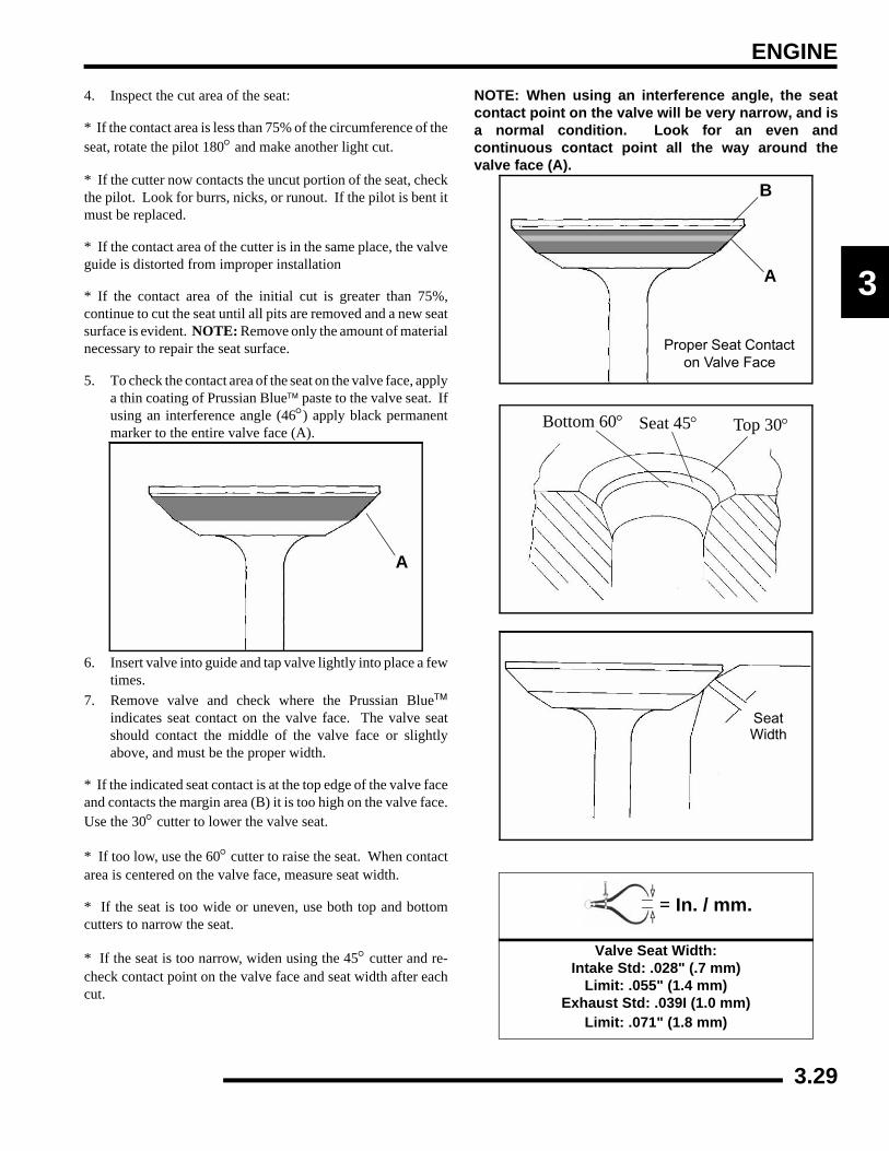
ENGINE
3
4. Inspect the cut area of the seat:
* If the contact area is less than 75% of the circumference of theseat, rotate the pilot 180° and make another light cut.
* If the cutter now contacts the uncut portion of the seat, checkthe pilot. Look for burrs, nicks, or runout. If the pilot is bent itmust be replaced.
* If the contact area of the cutter is in the same place, the valveguide is distorted from improper installation
* If the contact area of the initial cut is greater than 75%,continue to cut the seat until all pits are removed and a new seatsurface is evident. NOTE: Remove only the amount of materialnecessary to repair the seat surface.
5. To check the contact area of the seat on the valve face, applya thin coating of Prussian Blue™ paste to the valve seat. Ifusing an interference angle (46°) apply black permanentmarker to the entire valve face (A).
6. Insert valve into guide and tap valve lightly into place a fewtimes.
7. Remove valve and check where the Prussian Blue™indicates seat contact on the valve face. The valve seatshould contact the middle of the valve face or slightlyabove, and must be the proper width.
* If the indicated seat contact is at the top edge of the valve faceand contacts the margin area (B) it is too high on the valve face.Use the 30° cutter to lower the valve seat.
* If too low, use the 60° cutter to raise the seat. When contactarea is centered on the valve face, measure seat width.
* If the seat is too wide or uneven, use both top and bottomcutters to narrow the seat.
* If the seat is too narrow, widen using the 45° cutter and re-check contact point on the valve face and seat width after eachcut.
NOTE: When using an interference angle, the seatcontact point on the valve will be very narrow, and isa normal condition. Look for an even andcontinuous contact point all the way around thevalve face (A).
A
= In. / mm.
Valve Seat Width:Intake Std: .028" (.7 mm)
Limit: .055" (1.4 mm)Exhaust Std: .039I (1.0 mm)
Limit: .071" (1.8 mm)
B
A
Proper Seat Contact on Valve Face
Bottom 60° Seat 45° Top 30°
SeatWidth
3.29
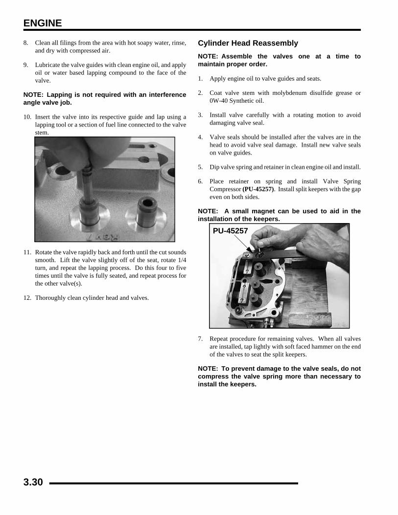
ENGINE
8. Clean all filings from the area with hot soapy water, rinse,and dry with compressed air.
9. Lubricate the valve guides with clean engine oil, and applyoil or water based lapping compound to the face of thevalve.
NOTE: Lapping is not required with an interferenceangle valve job.
10. Insert the valve into its respective guide and lap using alapping tool or a section of fuel line connected to the valvestem.
11. Rotate the valve rapidly back and forth until the cut soundssmooth. Lift the valve slightly off of the seat, rotate 1/4turn, and repeat the lapping process. Do this four to fivetimes until the valve is fully seated, and repeat process forthe other valve(s).
12. Thoroughly clean cylinder head and valves.
Cylinder Head ReassemblyNOTE: Assemble the valves one at a time tomaintain proper order.
1. Apply engine oil to valve guides and seats.
2. Coat valve stem with molybdenum disulfide grease or0W-40 Synthetic oil.
3. Install valve carefully with a rotating motion to avoiddamaging valve seal.
4. Valve seals should be installed after the valves are in thehead to avoid valve seal damage. Install new valve sealson valve guides.
5. Dip valve spring and retainer in clean engine oil and install.
6. Place retainer on spring and install Valve SpringCompressor (PU-45257). Install split keepers with the gapeven on both sides.
NOTE: A small magnet can be used to aid in theinstallation of the keepers.
7. Repeat procedure for remaining valves. When all valvesare installed, tap lightly with soft faced hammer on the endof the valves to seat the split keepers.
NOTE: To prevent damage to the valve seals, do notcompress the valve spring more than necessary toinstall the keepers.
PU-45257
3.30
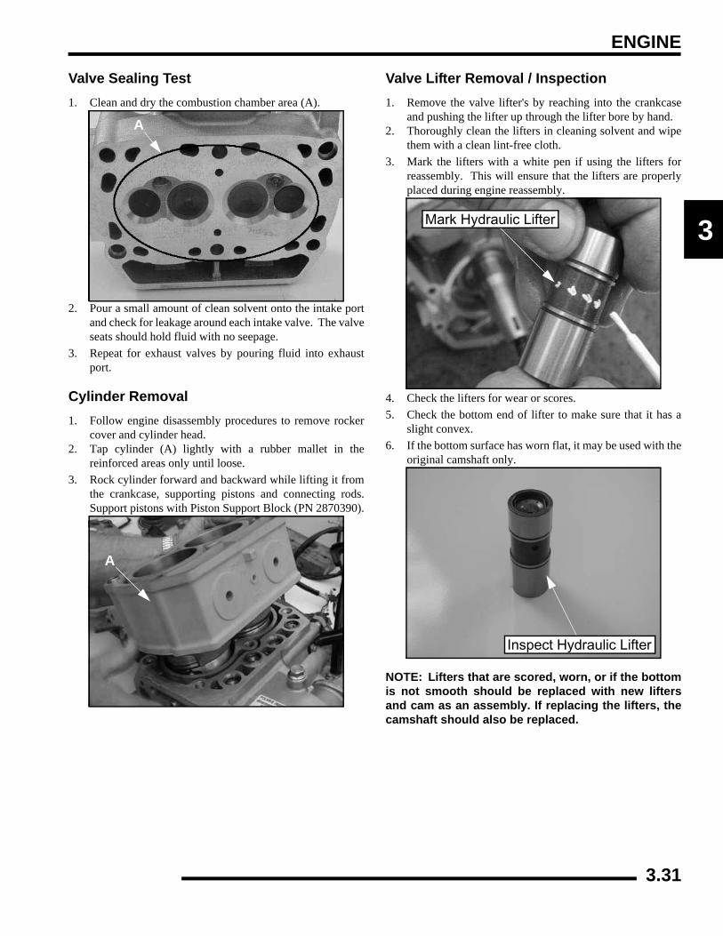
ENGINE
3
Valve Sealing Test1. Clean and dry the combustion chamber area (A).
2. Pour a small amount of clean solvent onto the intake portand check for leakage around each intake valve. The valveseats should hold fluid with no seepage.
3. Repeat for exhaust valves by pouring fluid into exhaustport.
Cylinder Removal1. Follow engine disassembly procedures to remove rocker
cover and cylinder head.2. Tap cylinder (A) lightly with a rubber mallet in the
reinforced areas only until loose.3. Rock cylinder forward and backward while lifting it from
the crankcase, supporting pistons and connecting rods.Support pistons with Piston Support Block (PN 2870390).
Valve Lifter Removal / Inspection1. Remove the valve lifter's by reaching into the crankcase
and pushing the lifter up through the lifter bore by hand.2. Thoroughly clean the lifters in cleaning solvent and wipe
them with a clean lint-free cloth.3. Mark the lifters with a white pen if using the lifters for
reassembly. This will ensure that the lifters are properlyplaced during engine reassembly.
4. Check the lifters for wear or scores.5. Check the bottom end of lifter to make sure that it has a
slight convex.6. If the bottom surface has worn flat, it may be used with the
original camshaft only.
NOTE: Lifters that are scored, worn, or if the bottomis not smooth should be replaced with new liftersand cam as an assembly. If replacing the lifters, thecamshaft should also be replaced.
A
A
Mark Hydraulic Lifter
Inspect Hydraulic Lifter
3.31
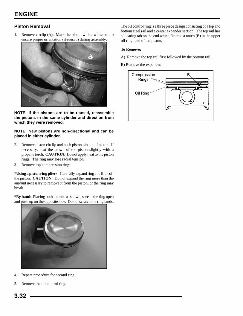
ENGINE
Piston Removal1. Remove circlip (A). Mark the piston with a white pen to
ensure proper orientation (if reused) during assembly.
NOTE: If the pistons are to be reused, reassemblethe pistons in the same cylinder and direction fromwhich they were removed.
NOTE: New pistons are non-directional and can beplaced in either cylinder.
2. Remove piston circlip and push piston pin out of piston. Ifnecessary, heat the crown of the piston slightly with apropane torch. CAUTION: Do not apply heat to the pistonrings. The ring may lose radial tension.
3. Remove top compression ring:
*Using a piston ring pliers: Carefully expand ring and lift it offthe piston. CAUTION: Do not expand the ring more than theamount necessary to remove it from the piston, or the ring maybreak.
*By hand: Placing both thumbs as shown, spread the ring openand push up on the opposite side. Do not scratch the ring lands.
4. Repeat procedure for second ring.
5. Remove the oil control ring.
The oil control ring is a three piece design consisting of a top andbottom steel rail and a center expander section. The top rail hasa locating tab on the end which fits into a notch (B) in the upperoil ring land of the piston.
To Remove:
A) Remove the top rail first followed by the bottom rail.
B) Remove the expander.
Compression Rings
Oil Ring
B
3.32
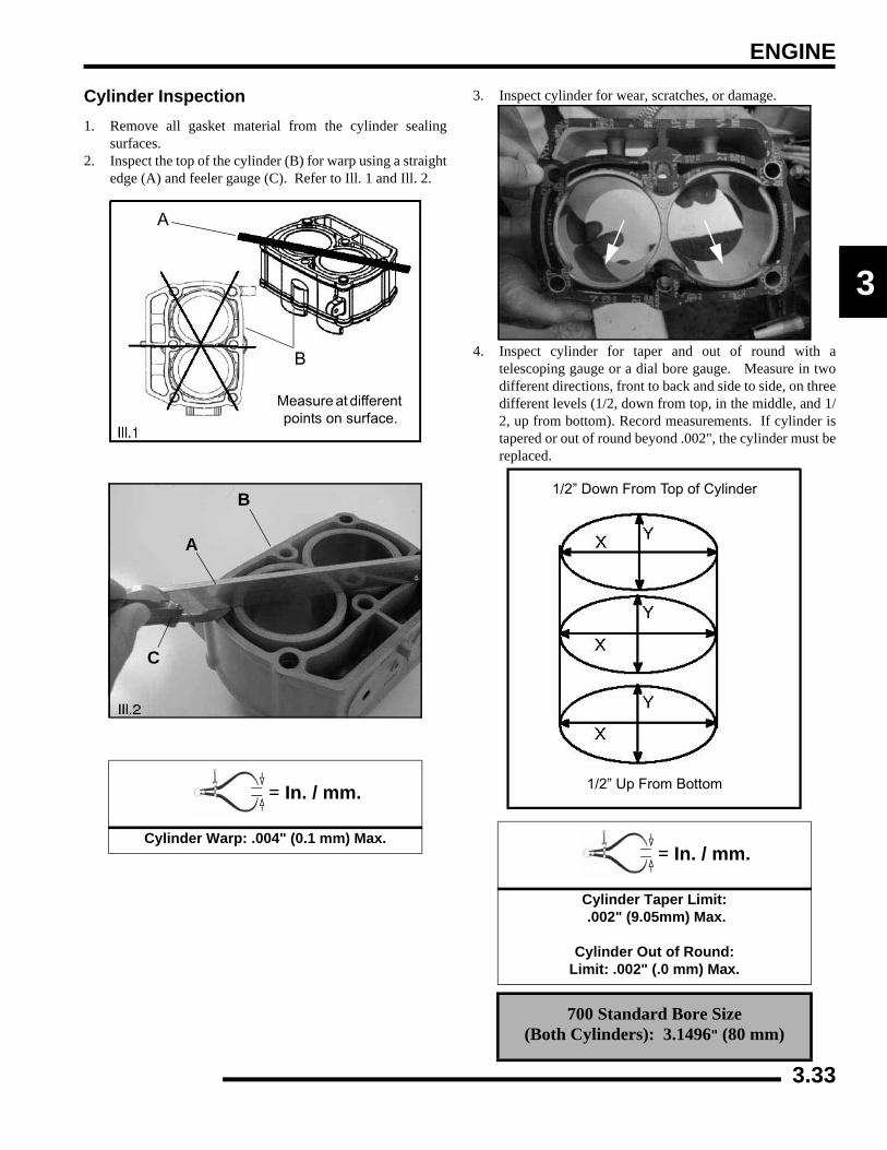
ENGINE
3
Cylinder Inspection1. Remove all gasket material from the cylinder sealing
surfaces.2. Inspect the top of the cylinder (B) for warp using a straight
edge (A) and feeler gauge (C). Refer to Ill. 1 and Ill. 2.
3. Inspect cylinder for wear, scratches, or damage.
4. Inspect cylinder for taper and out of round with atelescoping gauge or a dial bore gauge. Measure in twodifferent directions, front to back and side to side, on threedifferent levels (1/2, down from top, in the middle, and 1/2, up from bottom). Record measurements. If cylinder istapered or out of round beyond .002", the cylinder must bereplaced.
= In. / mm.
Cylinder Warp: .004" (0.1 mm) Max.
Measure at different points on surface.
A
B
A
B
C
= In. / mm.
Cylinder Taper Limit: .002" (9.05mm) Max.
Cylinder Out of Round:
Limit: .002" (.0 mm) Max.
700 Standard Bore Size (Both Cylinders): 3.1496" (80 mm)
1/2” Down From Top of Cylinder
1/2” Up From Bottom
3.33
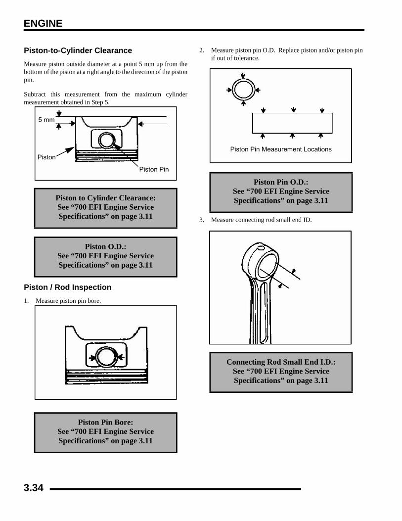
ENGINE
Piston-to-Cylinder ClearanceMeasure piston outside diameter at a point 5 mm up from thebottom of the piston at a right angle to the direction of the pistonpin.
Subtract this measurement from the maximum cylindermeasurement obtained in Step 5.
Piston / Rod Inspection1. Measure piston pin bore.
2. Measure piston pin O.D. Replace piston and/or piston pinif out of tolerance.
3. Measure connecting rod small end ID.
Piston to Cylinder Clearance: See “700 EFI Engine Service Specifications” on page 3.11
Piston O.D.: See “700 EFI Engine Service Specifications” on page 3.11
Piston Pin Bore: See “700 EFI Engine Service Specifications” on page 3.11
5 mm
Piston
Piston Pin
Piston Pin O.D.: See “700 EFI Engine Service Specifications” on page 3.11
Connecting Rod Small End I.D.: See “700 EFI Engine Service Specifications” on page 3.11
Piston Pin Measurement Locations
3.34
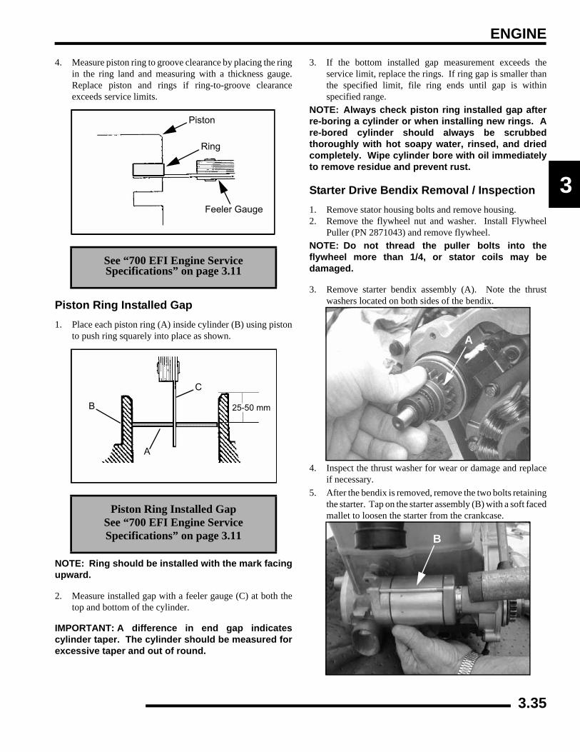
ENGINE
3
4. Measure piston ring to groove clearance by placing the ringin the ring land and measuring with a thickness gauge.Replace piston and rings if ring-to-groove clearanceexceeds service limits.
Piston Ring Installed Gap1. Place each piston ring (A) inside cylinder (B) using piston
to push ring squarely into place as shown.
NOTE: Ring should be installed with the mark facingupward.
2. Measure installed gap with a feeler gauge (C) at both thetop and bottom of the cylinder.
IMPORTANT: A difference in end gap indicatescylinder taper. The cylinder should be measured forexcessive taper and out of round.
3. If the bottom installed gap measurement exceeds theservice limit, replace the rings. If ring gap is smaller thanthe specified limit, file ring ends until gap is withinspecified range.
NOTE: Always check piston ring installed gap afterre-boring a cylinder or when installing new rings. Are-bored cylinder should always be scrubbedthoroughly with hot soapy water, rinsed, and driedcompletely. Wipe cylinder bore with oil immediatelyto remove residue and prevent rust.
Starter Drive Bendix Removal / Inspection1. Remove stator housing bolts and remove housing.2. Remove the flywheel nut and washer. Install Flywheel
Puller (PN 2871043) and remove flywheel.NOTE: Do not thread the puller bolts into theflywheel more than 1/4, or stator coils may bedamaged.
3. Remove starter bendix assembly (A). Note the thrustwashers located on both sides of the bendix.
4. Inspect the thrust washer for wear or damage and replaceif necessary.
5. After the bendix is removed, remove the two bolts retainingthe starter. Tap on the starter assembly (B) with a soft facedmallet to loosen the starter from the crankcase.
See “700 EFI Engine Service Specifications” on page 3.11
Piston Ring Installed Gap See “700 EFI Engine Service Specifications” on page 3.11
Piston
Ring
Feeler Gauge
A
B
C
25-50 mm
A
B
3.35

ENGINE
6. Inspect gear teeth on starter drive (A). Replace starter driveif gear teeth are cracked, worn, or broken.
7. Inspect the bendix bushing (C) in the mag cover for wear.Replace as needed.
Flywheel / Stator Removal / Inspection1. Remove stator housing bolts and remove housing.
2. Remove flywheel nut and washer.
3. Install Flywheel Puller (PN 2871043) and remove flywheel(A).
4. Use caution when removing the wire holddown (B) and thestator assembly (D). Do not tap or bump the gear /statorhousing cover or the stator. This could cause the sealaround the gear/stator housing cover and the crankcase tobreak, causing a leak.
5. Remove the bendix (E) if necessary.
Engine Crankcase Disassembly / Inspection1. Remove the stator cover (A) and water pump cover (B).
CAUTION
Do not thread the puller bolts into the flywheel more than 1/4, or stator coils may be damaged.
C
Remove Stator Cover
A2871043
EB
D
A
B
3.36
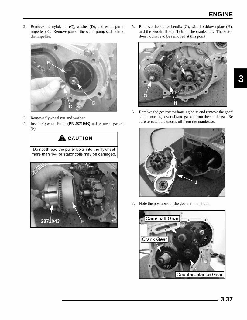
ENGINE
3
2. Remove the nylok nut (C), washer (D), and water pumpimpeller (E). Remove part of the water pump seal behindthe impeller.
3. Remove flywheel nut and washer.4. Install Flywheel Puller (PN 2871043) and remove flywheel
(F).
5. Remove the starter bendix (G), wire holddown plate (H),and the woodruff key (I) from the crankshaft. The statordoes not have to be removed at this point.
6. Remove the gear/stator housing bolts and remove the gear/stator housing cover (J) and gasket from the crankcase. Besure to catch the excess oil from the crankcase.
7. Note the positions of the gears in the photo.
CAUTION
Do not thread the puller bolts into the flywheel more than 1/4, or stator coils may be damaged.
D
E
C
F2871043
GH
I
J
Counterbalance Gear
Camshaft Gear
Crank Gear
3.37
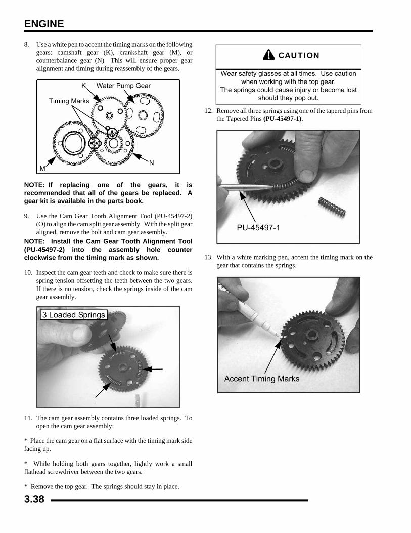
ENGINE
8. Use a white pen to accent the timing marks on the followinggears: camshaft gear (K), crankshaft gear (M), orcounterbalance gear (N) This will ensure proper gearalignment and timing during reassembly of the gears.
NOTE: If replacing one of the gears, it isrecommended that all of the gears be replaced. Agear kit is available in the parts book.
9. Use the Cam Gear Tooth Alignment Tool (PU-45497-2)(O) to align the cam split gear assembly. With the split gearaligned, remove the bolt and cam gear assembly.
NOTE: Install the Cam Gear Tooth Alignment Tool(PU-45497-2) into the assembly hole counterclockwise from the timing mark as shown.
10. Inspect the cam gear teeth and check to make sure there isspring tension offsetting the teeth between the two gears.If there is no tension, check the springs inside of the camgear assembly.
11. The cam gear assembly contains three loaded springs. Toopen the cam gear assembly:
* Place the cam gear on a flat surface with the timing mark sidefacing up.
* While holding both gears together, lightly work a smallflathead screwdriver between the two gears.
* Remove the top gear. The springs should stay in place.
12. Remove all three springs using one of the tapered pins fromthe Tapered Pins (PU-45497-1).
13. With a white marking pen, accent the timing mark on thegear that contains the springs.
MN
K
Timing Marks
Water Pump Gear
3 Loaded Springs
CAUTION
Wear safety glasses at all times. Use caution when working with the top gear.
The springs could cause injury or become lost should they pop out.
PU-45497-1
Accent Timing Marks
3.38

ENGINE
3
14. Inspect the gear teeth and the three tabs on the gears forwear.
15. Install the new springs into the grooves of the cam gear.
16. Insert the pointed dowels from the Tapered Pins (PU-45497-1) into the cam gear.
To Assemble:
* Hold the spring with one finger.* Start the pointed end of the tapered pin into the cam gear holeand slowly push the dowel through the hole until the end of thedowel is almost flush with the spring.
* Perform this procedure with all three tapered pins.* Do not push the pins too far through or the springs will popout.
NOTE: Do not remove the tapered pins at this time.
17. Note in the photograph that the Tapered Pins (PU-45497-1) are below flush with end of the springs. This helps toalign the three gear tabs during the next step.
18. Line up the two gears using the timing marks and the threegear tabs that were referenced earlier. Push the gears backtogether, using both hands and hold securely.
Inspect Teeth & Tabs
Replace 3 Springs
Install Springs
PU-45497-1
Cam Gear Spring Installation Tool Kit: (PU-45497)
Tapered Pins: (PU-45497-1)
Cam Gear Tooth Align Tool: (PU-45497-2)
PU-45497-1
Align Timing Marks
3.39
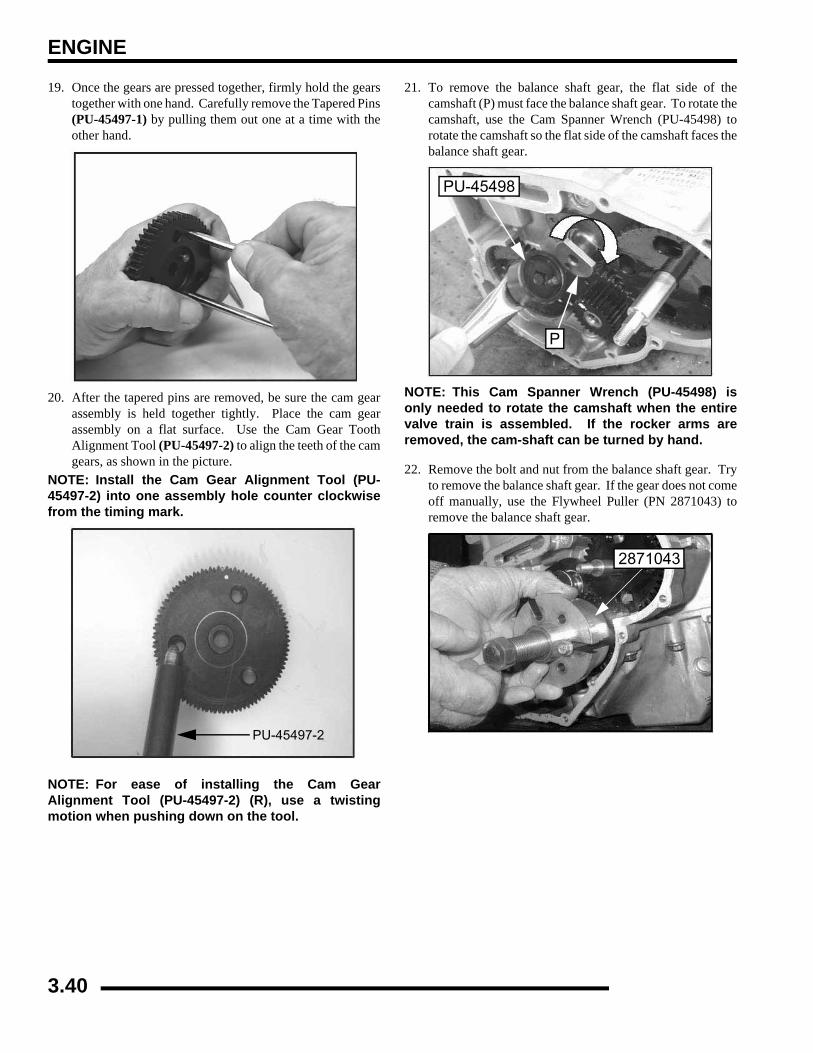
ENGINE
19. Once the gears are pressed together, firmly hold the gearstogether with one hand. Carefully remove the Tapered Pins(PU-45497-1) by pulling them out one at a time with theother hand.
20. After the tapered pins are removed, be sure the cam gearassembly is held together tightly. Place the cam gearassembly on a flat surface. Use the Cam Gear ToothAlignment Tool (PU-45497-2) to align the teeth of the camgears, as shown in the picture.
NOTE: Install the Cam Gear Alignment Tool (PU-45497-2) into one assembly hole counter clockwisefrom the timing mark.
NOTE: For ease of installing the Cam GearAlignment Tool (PU-45497-2) (R), use a twistingmotion when pushing down on the tool.
21. To remove the balance shaft gear, the flat side of thecamshaft (P) must face the balance shaft gear. To rotate thecamshaft, use the Cam Spanner Wrench (PU-45498) torotate the camshaft so the flat side of the camshaft faces thebalance shaft gear.
NOTE: This Cam Spanner Wrench (PU-45498) isonly needed to rotate the camshaft when the entirevalve train is assembled. If the rocker arms areremoved, the cam-shaft can be turned by hand.
22. Remove the bolt and nut from the balance shaft gear. Tryto remove the balance shaft gear. If the gear does not comeoff manually, use the Flywheel Puller (PN 2871043) toremove the balance shaft gear.
PU-45497-2
PU-45498
P
2871043
3.40

ENGINE
3
23. Inspect the crankshaft gear (Q) for broken or worn teeth. Ifthe crankshaft gear does not need to be replaced, it does notneed to be removed. If the crankshaft gear is damaged,remove the crankshaft gear with the Flywheel Puller(PN 2871043).
24. Install the two puller bolts (R). Tighten the puller bolts upso that the bolts are at equal length.
25. Install the Flywheel Puller (PN 2871043) and remove thecrankshaft gear, if needed.
26. Rotate the water/oil pump gear (S), so that all four bolts arevisible though the gear. Remove the four bolts with a hexwrench. Pull out the pump.
27. Inspect the oil pump rotors for wear. Mark the rotors witha white pen to ensure upon reassembly that the correct sidesof the rotors are installed and mesh with the same edges aspreviously installed.
NOTE: If replacing the old rotors, new replacementrotors will fit into the old oil/water pump housing.
28. Use a feeler gauge to measure the clearance between thetwo rotors. Measure the gap between the two rotor tips asshown below. The clearance should not exceed 0.006"(0.15 mm).
Q
R
2871043
S
Mark Rotors
Max Tip Clearance0.006” (0.15 mm)
3.41
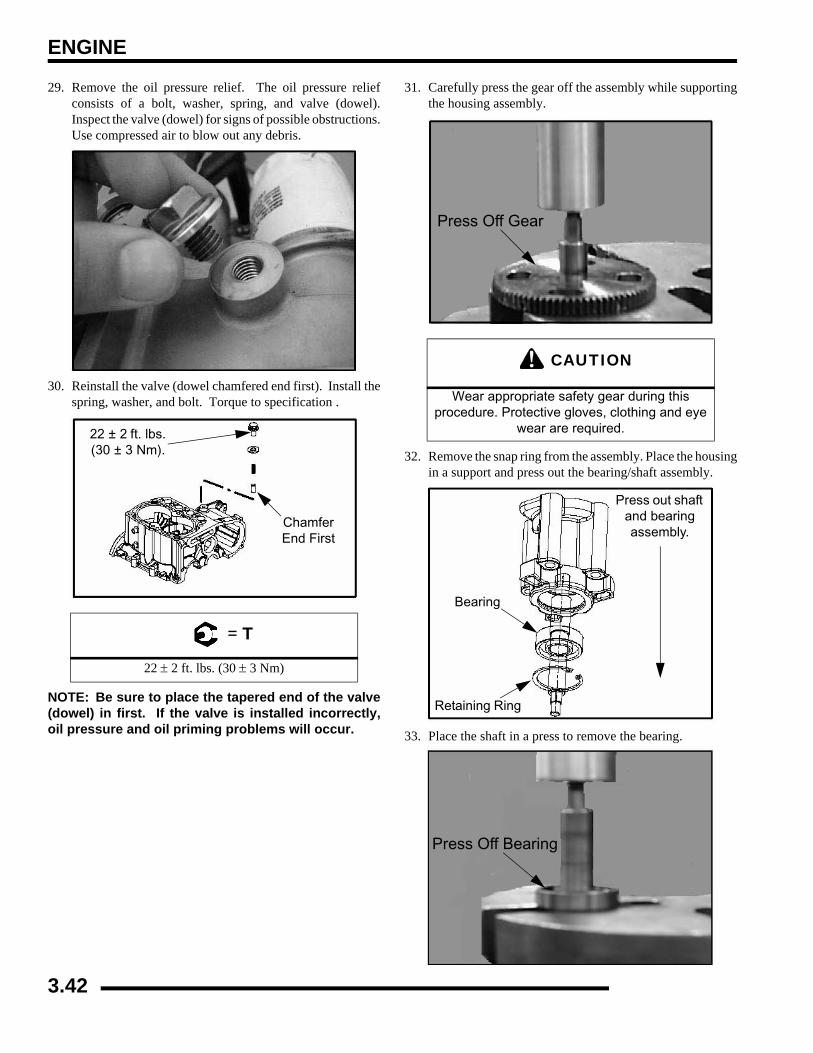
ENGINE
29. Remove the oil pressure relief. The oil pressure reliefconsists of a bolt, washer, spring, and valve (dowel).Inspect the valve (dowel) for signs of possible obstructions.Use compressed air to blow out any debris.
30. Reinstall the valve (dowel chamfered end first). Install thespring, washer, and bolt. Torque to specification .
NOTE: Be sure to place the tapered end of the valve(dowel) in first. If the valve is installed incorrectly,oil pressure and oil priming problems will occur.
31. Carefully press the gear off the assembly while supportingthe housing assembly.
32. Remove the snap ring from the assembly. Place the housingin a support and press out the bearing/shaft assembly.
33. Place the shaft in a press to remove the bearing.
= T
22 ± 2 ft. lbs. (30 ± 3 Nm)
22 ± 2 ft. lbs. (30 ± 3 Nm).
Chamfer End First
CAUTION
Wear appropriate safety gear during this procedure. Protective gloves, clothing and eye
wear are required.
Press Off Gear
Press out shaft and bearing assembly.
Bearing
Retaining Ring
Press Off Bearing
3.42
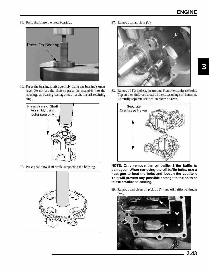
ENGINE
3
34. Press shaft into the new bearing..
35. Press the bearing/shaft assembly using the bearing's outerrace. Do not use the shaft to press the assembly into thehousing, as bearing damage may result. Install retainingring.
36. Press gear onto shaft while supporting the housing.
37. Remove thrust plate (U).
38. Remove PTO end engine mount. Remove crankcase bolts.Tap on the reinforced areas on the cases using soft hammer.Carefully separate the two crankcase halves.
NOTE: Only remove the oil baffle if the baffle isdamaged. When removing the oil baffle bolts, use aheat gun to heat the bolts and loosen the Loctite™.This will prevent any possible damage to the bolts orto the crankcase casting.
39. Remove and clean oil pick up (V) and oil baffle weldment(W).
Press On Bearing
Press Bearing / Shaft Assembly using outer race only
U
Separate Crankcase Halves
W
V
3.43
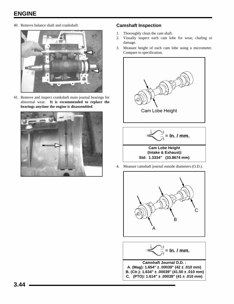
ENGINE
40. Remove balance shaft and crankshaft.
41. Remove and inspect crankshaft main journal bearings forabnormal wear. It is recommended to replace thebearings anytime the engine is disassembled.
Camshaft Inspection1. Thoroughly clean the cam shaft.2. Visually inspect each cam lobe for wear, chafing or
damage.3. Measure height of each cam lobe using a micrometer.
Compare to specification.
4. Measure camshaft journal outside diameters (O.D.).
= In. / mm.
Cam Lobe Height (Intake & Exhaust):
Std: 1.3334" (33.8674 mm)
= In. / mm.
Camshaft Journal O.D. :A. (Mag): 1.654" ± .00039" (42 ± .010 mm)
B. (Ctr.): 1.634" ± .00039" (41.50 ± .010 mm)C. (PTO): 1.614" ± .00039" (41 ± .010 mm)
Cam Lobe Height
A
B
C
3.44
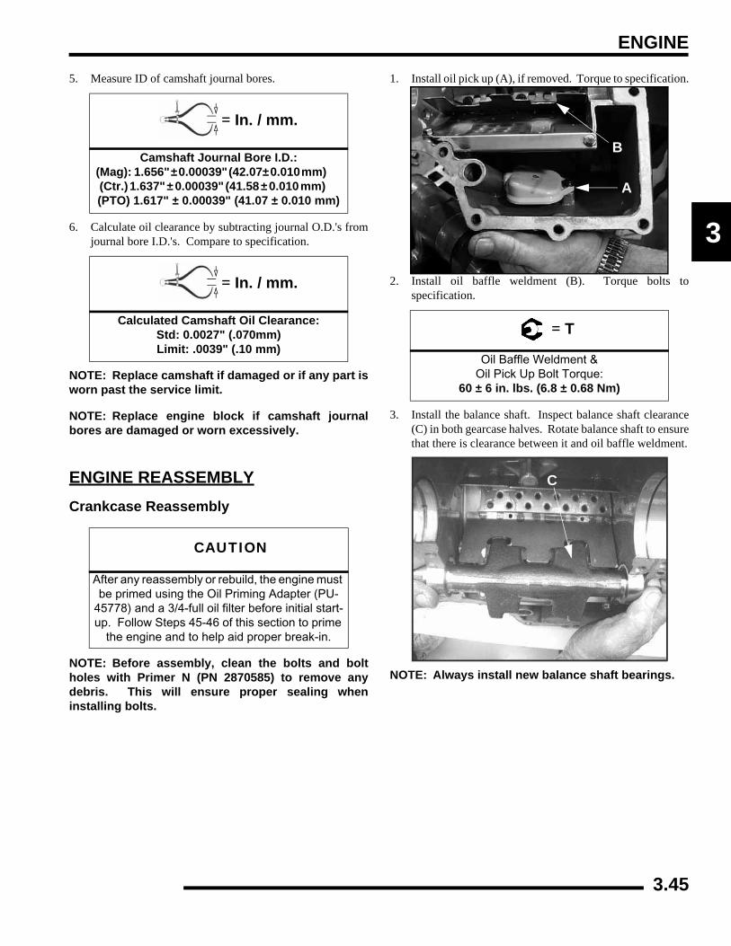
ENGINE
3
5. Measure ID of camshaft journal bores.
6. Calculate oil clearance by subtracting journal O.D.'s fromjournal bore I.D.'s. Compare to specification.
NOTE: Replace camshaft if damaged or if any part isworn past the service limit.
NOTE: Replace engine block if camshaft journalbores are damaged or worn excessively.
ENGINE REASSEMBLYCrankcase Reassembly
NOTE: Before assembly, clean the bolts and boltholes with Primer N (PN 2870585) to remove anydebris. This will ensure proper sealing wheninstalling bolts.
1. Install oil pick up (A), if removed. Torque to specification.
2. Install oil baffle weldment (B). Torque bolts tospecification.
3. Install the balance shaft. Inspect balance shaft clearance(C) in both gearcase halves. Rotate balance shaft to ensurethat there is clearance between it and oil baffle weldment.
NOTE: Always install new balance shaft bearings.
= In. / mm.
Camshaft Journal Bore I.D.: (Mag): 1.656" ± 0.00039" (42.07± 0.010 mm) (Ctr.) 1.637" ± 0.00039" (41.58 ± 0.010 mm) (PTO) 1.617" ± 0.00039" (41.07 ± 0.010 mm)
= In. / mm.
Calculated Camshaft Oil Clearance: Std: 0.0027" (.070mm)Limit: .0039" (.10 mm)
CAUTION
After any reassembly or rebuild, the engine must be primed using the Oil Priming Adapter (PU-
45778) and a 3/4-full oil filter before initial start-up. Follow Steps 45-46 of this section to prime
the engine and to help aid proper break-in.
= T
Oil Baffle Weldment & Oil Pick Up Bolt Torque:
60 ± 6 in. lbs. (6.8 ± 0.68 Nm)
B
A
C
3.45
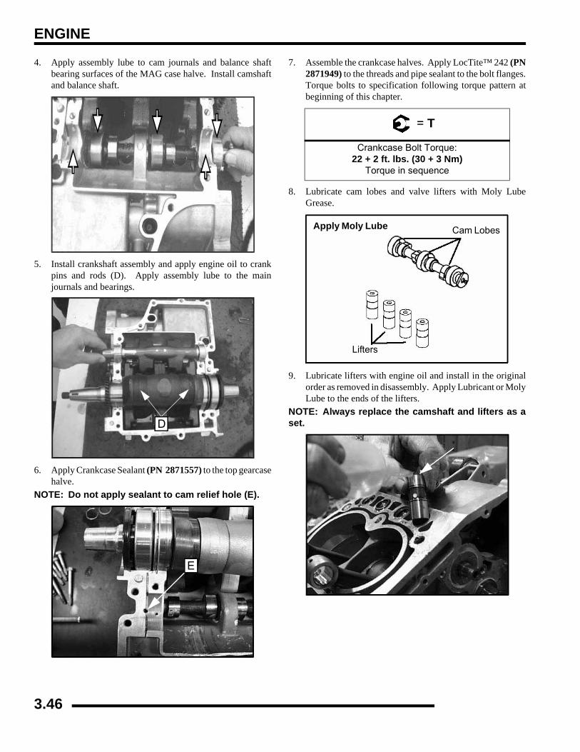
ENGINE
4. Apply assembly lube to cam journals and balance shaftbearing surfaces of the MAG case halve. Install camshaftand balance shaft.
5. Install crankshaft assembly and apply engine oil to crankpins and rods (D). Apply assembly lube to the mainjournals and bearings.
6. Apply Crankcase Sealant (PN 2871557) to the top gearcasehalve.
NOTE: Do not apply sealant to cam relief hole (E).
7. Assemble the crankcase halves. Apply LocTite™ 242 (PN2871949) to the threads and pipe sealant to the bolt flanges.Torque bolts to specification following torque pattern atbeginning of this chapter.
8. Lubricate cam lobes and valve lifters with Moly LubeGrease.
9. Lubricate lifters with engine oil and install in the originalorder as removed in disassembly. Apply Lubricant or MolyLube to the ends of the lifters.
NOTE: Always replace the camshaft and lifters as aset.D
E
= T
Crankcase Bolt Torque:22 + 2 ft. lbs. (30 + 3 Nm)
Torque in sequence
Apply Moly Lube Cam Lobes
Lifters
3.46

ENGINE
3
10. Lubricate connecting rods with 0W-40 engine oil.
11. Install new cylinder gasket on crankcase. Align gasket onthe dowel pins for proper gasket alignment.
12. Orientate the piston rings on the piston before installationinto the cylinders. Set the gaps of the rings every 120°(See Illustration Below).
13. Install piston assemblies into cylinder aligning the pistonpin holes, to ensure proper alignment of the pistons to theconnecting rods upon assembly. Partially install the pistonpins into the pistons.
NOTE: To help align the pistons, slide a rod that isclose to the same diameter as the wrist pin holes toproperly align them in the cylinder.
14. Position cylinder and piston assemblies onto the connectingrods and push the piston pins through the piston andconnecting rods.
15. Install the piston pin circlips. The circlip ends should beinstalled at the 12 O'clock position.
Piston Ring Orientation
1
2
3
1. Top Ring 2. Second Ring
3. Oil Ring
Push in Piston Pins
Piston Pin Cirlcip in 12 O’clock position
3.47
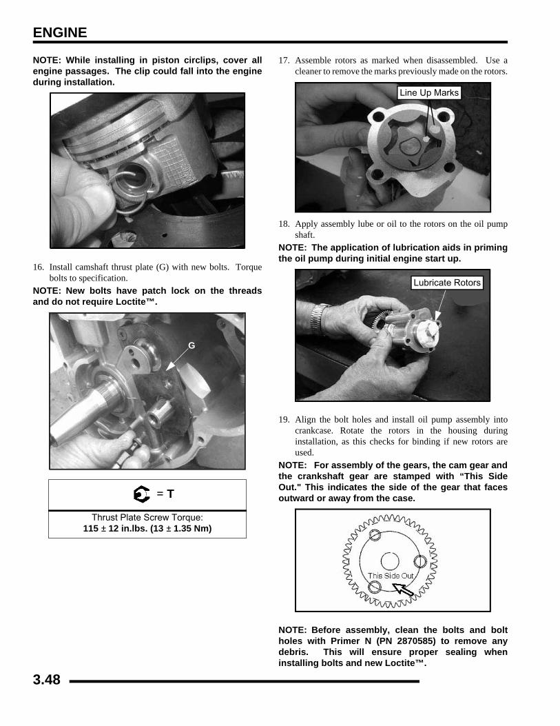
ENGINE
NOTE: While installing in piston circlips, cover allengine passages. The clip could fall into the engineduring installation.
16. Install camshaft thrust plate (G) with new bolts. Torquebolts to specification.
NOTE: New bolts have patch lock on the threadsand do not require Loctite™.
17. Assemble rotors as marked when disassembled. Use acleaner to remove the marks previously made on the rotors.
18. Apply assembly lube or oil to the rotors on the oil pumpshaft.
NOTE: The application of lubrication aids in primingthe oil pump during initial engine start up.
19. Align the bolt holes and install oil pump assembly intocrankcase. Rotate the rotors in the housing duringinstallation, as this checks for binding if new rotors areused.
NOTE: For assembly of the gears, the cam gear andthe crankshaft gear are stamped with “This SideOut." This indicates the side of the gear that facesoutward or away from the case.
NOTE: Before assembly, clean the bolts and boltholes with Primer N (PN 2870585) to remove anydebris. This will ensure proper sealing wheninstalling bolts and new Loctite™.
= T
Thrust Plate Screw Torque: 115 ± 12 in.lbs. (13 ± 1.35 Nm)
G
Line Up Marks
Lubricate Rotors
3.48
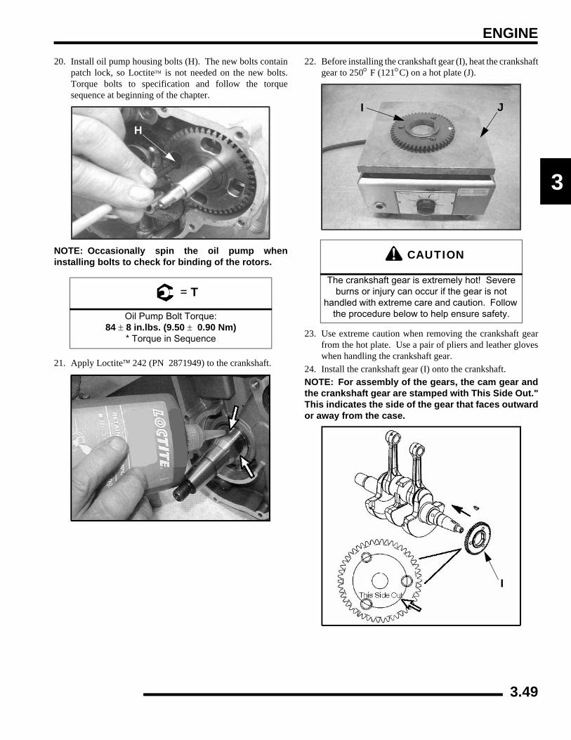
ENGINE
3
20. Install oil pump housing bolts (H). The new bolts containpatch lock, so Loctite™ is not needed on the new bolts.Torque bolts to specification and follow the torquesequence at beginning of the chapter.
NOTE: Occasionally spin the oil pump wheninstalling bolts to check for binding of the rotors.
21. Apply Loctite™ 242 (PN 2871949) to the crankshaft.
22. Before installing the crankshaft gear (I), heat the crankshaftgear to 250° F (121°C) on a hot plate (J).
23. Use extreme caution when removing the crankshaft gearfrom the hot plate. Use a pair of pliers and leather gloveswhen handling the crankshaft gear.
24. Install the crankshaft gear (I) onto the crankshaft.NOTE: For assembly of the gears, the cam gear andthe crankshaft gear are stamped with This Side Out."This indicates the side of the gear that faces outwardor away from the case.
= T
Oil Pump Bolt Torque: 84 ± 8 in.lbs. (9.50 ± 0.90 Nm)
* Torque in Sequence
H
CAUTION
The crankshaft gear is extremely hot! Severe burns or injury can occur if the gear is not
handled with extreme care and caution. Follow the procedure below to help ensure safety.
I J
I
3.49
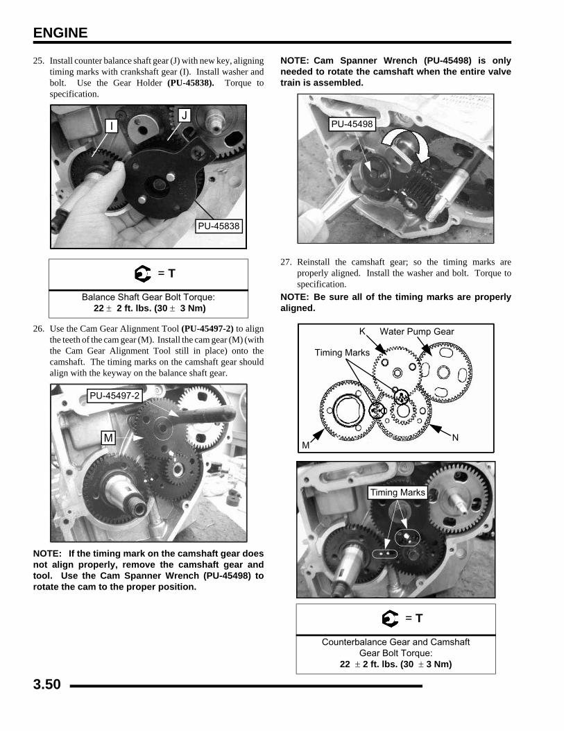
ENGINE
25. Install counter balance shaft gear (J) with new key, aligningtiming marks with crankshaft gear (I). Install washer andbolt. Use the Gear Holder (PU-45838). Torque tospecification.
26. Use the Cam Gear Alignment Tool (PU-45497-2) to alignthe teeth of the cam gear (M). Install the cam gear (M) (withthe Cam Gear Alignment Tool still in place) onto thecamshaft. The timing marks on the camshaft gear shouldalign with the keyway on the balance shaft gear.
NOTE: If the timing mark on the camshaft gear doesnot align properly, remove the camshaft gear andtool. Use the Cam Spanner Wrench (PU-45498) torotate the cam to the proper position.
NOTE: Cam Spanner Wrench (PU-45498) is onlyneeded to rotate the camshaft when the entire valvetrain is assembled.
27. Reinstall the camshaft gear; so the timing marks areproperly aligned. Install the washer and bolt. Torque tospecification.
NOTE: Be sure all of the timing marks are properlyaligned.
= T
Balance Shaft Gear Bolt Torque: 22 ± 2 ft. lbs. (30 ± 3 Nm)
PU-45838
JI
PU-45497-2
M
= T
Counterbalance Gear and Camshaft Gear Bolt Torque:
22 ± 2 ft. lbs. (30 ± 3 Nm)
PU-45498
MN
K
Timing Marks
Water Pump Gear
Timing Marks
3.50
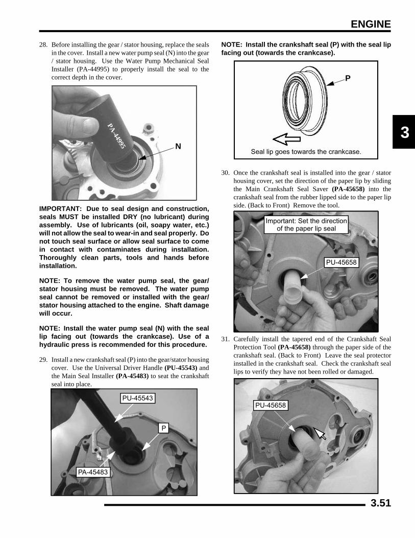
ENGINE
3
28. Before installing the gear / stator housing, replace the sealsin the cover. Install a new water pump seal (N) into the gear/ stator housing. Use the Water Pump Mechanical SealInstaller (PA-44995) to properly install the seal to thecorrect depth in the cover.
IMPORTANT: Due to seal design and construction,seals MUST be installed DRY (no lubricant) duringassembly. Use of lubricants (oil, soapy water, etc.)will not allow the seal to wear-in and seal properly. Donot touch seal surface or allow seal surface to comein contact with contaminates during installation.Thoroughly clean parts, tools and hands beforeinstallation.
NOTE: To remove the water pump seal, the gear/stator housing must be removed. The water pumpseal cannot be removed or installed with the gear/stator housing attached to the engine. Shaft damagewill occur.
NOTE: Install the water pump seal (N) with the seallip facing out (towards the crankcase). Use of ahydraulic press is recommended for this procedure.
29. Install a new crankshaft seal (P) into the gear/stator housingcover. Use the Universal Driver Handle (PU-45543) andthe Main Seal Installer (PA-45483) to seat the crankshaftseal into place.
NOTE: Install the crankshaft seal (P) with the seal lipfacing out (towards the crankcase).
30. Once the crankshaft seal is installed into the gear / statorhousing cover, set the direction of the paper lip by slidingthe Main Crankshaft Seal Saver (PA-45658) into thecrankshaft seal from the rubber lipped side to the paper lipside. (Back to Front) Remove the tool.
31. Carefully install the tapered end of the Crankshaft SealProtection Tool (PA-45658) through the paper side of thecrankshaft seal. (Back to Front) Leave the seal protectorinstalled in the crankshaft seal. Check the crankshaft seallips to verify they have not been rolled or damaged.
PA-44995
O
N
PA-44995
PA-45483
PU-45543
P
P
Seal lip goes towards the crankcase.
PU-45658
Important: Set the directionof the paper lip seal
PU-45658
3.51
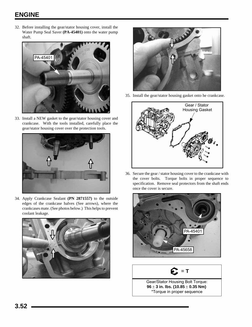
ENGINE
32. Before installing the gear/stator housing cover, install theWater Pump Seal Saver (PA-45401) onto the water pumpshaft.
33. Install a NEW gasket to the gear/stator housing cover andcrankcase. With the tools installed, carefully place thegear/stator housing cover over the protection tools.
34. Apply Crankcase Sealant (PN 2871557) to the outsideedges of the crankcase halves (See arrows), where thecrankcases mate. (See photos below.) This helps to preventcoolant leakage.
35. Install the gear/stator housing gasket onto he crankcase.
36. Secure the gear / stator housing cover to the crankcase withthe cover bolts. Torque bolts in proper sequence tospecification. Remove seal protectors from the shaft endsonce the cover is secure.
PA-45401
= T
Gear/Stator Housing Bolt Torque:96 ± 3 in. lbs. (10.85 ± 0.35 Nm)
*Torque in proper sequence
Gear / Stator Housing Gasket
PA-45658
PA-45401
3.52
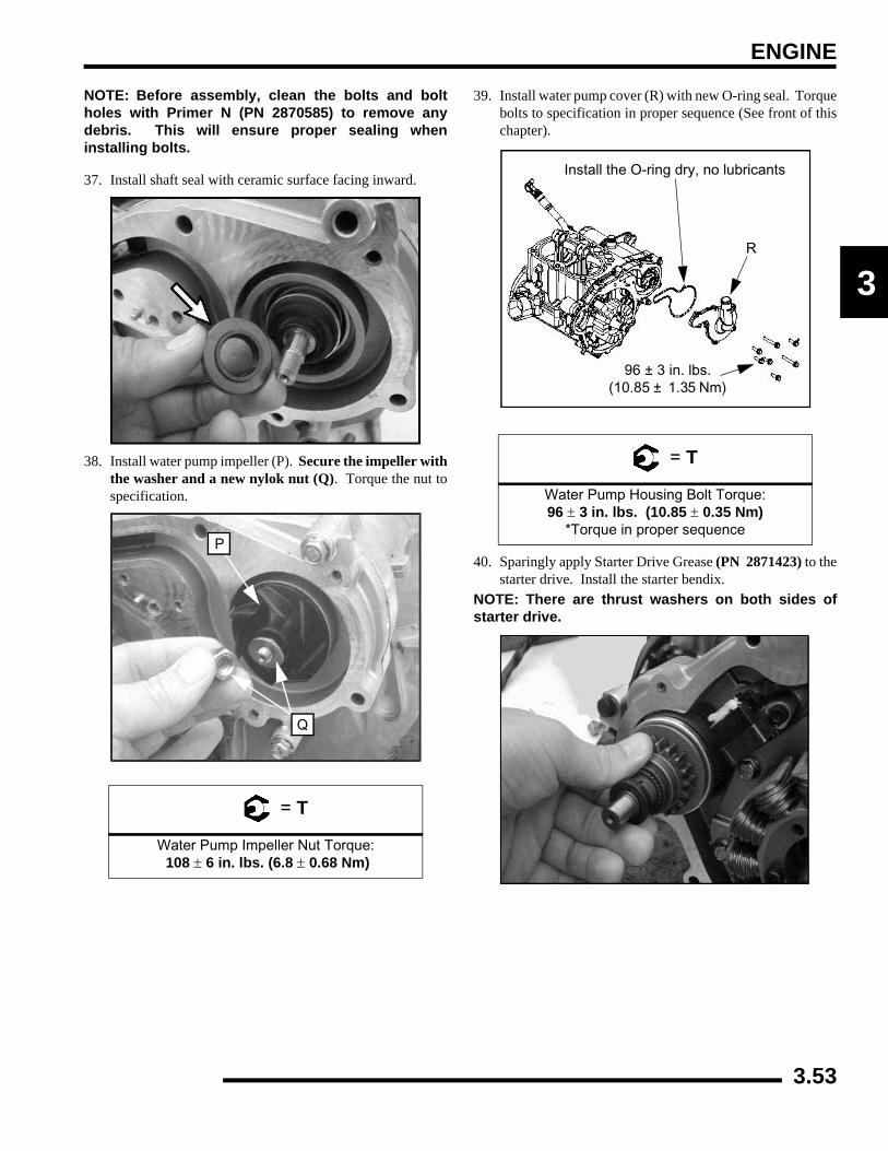
ENGINE
3
NOTE: Before assembly, clean the bolts and boltholes with Primer N (PN 2870585) to remove anydebris. This will ensure proper sealing wheninstalling bolts.
37. Install shaft seal with ceramic surface facing inward.
38. Install water pump impeller (P). Secure the impeller withthe washer and a new nylok nut (Q). Torque the nut tospecification.
39. Install water pump cover (R) with new O-ring seal. Torquebolts to specification in proper sequence (See front of thischapter).
40. Sparingly apply Starter Drive Grease (PN 2871423) to thestarter drive. Install the starter bendix.
NOTE: There are thrust washers on both sides ofstarter drive.
= T
Water Pump Impeller Nut Torque: 108 ± 6 in. lbs. (6.8 ± 0.68 Nm)
P
Q
= T
Water Pump Housing Bolt Torque: 96 ± 3 in. lbs. (10.85 ± 0.35 Nm)
*Torque in proper sequence
Install the O-ring dry, no lubricants
R
96 ± 3 in. lbs. (10.85 ± 1.35 Nm)
3.53
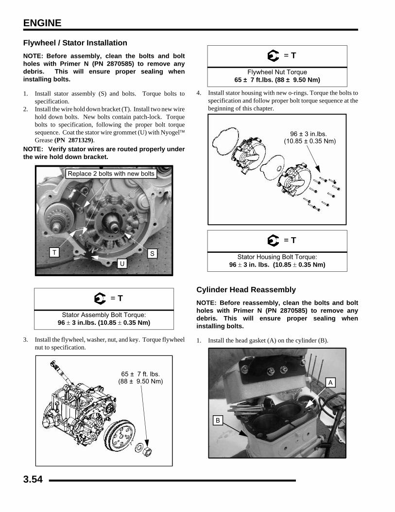
ENGINE
Flywheel / Stator InstallationNOTE: Before assembly, clean the bolts and boltholes with Primer N (PN 2870585) to remove anydebris. This will ensure proper sealing wheninstalling bolts.
1. Install stator assembly (S) and bolts. Torque bolts tospecification.
2. Install the wire hold down bracket (T). Install two new wirehold down bolts. New bolts contain patch-lock. Torquebolts to specification, following the proper bolt torquesequence. Coat the stator wire grommet (U) with Nyogel™Grease (PN 2871329).
NOTE: Verify stator wires are routed properly underthe wire hold down bracket.
3. Install the flywheel, washer, nut, and key. Torque flywheelnut to specification.
4. Install stator housing with new o-rings. Torque the bolts tospecification and follow proper bolt torque sequence at thebeginning of this chapter.
Cylinder Head ReassemblyNOTE: Before reassembly, clean the bolts and boltholes with Primer N (PN 2870585) to remove anydebris. This will ensure proper sealing wheninstalling bolts.
1. Install the head gasket (A) on the cylinder (B).
= T
Stator Assembly Bolt Torque: 96 ± 3 in.lbs. (10.85 ± 0.35 Nm)
U
T S
Replace 2 bolts with new bolts
65 ± 7 ft. lbs.(88 ± 9.50 Nm)
= T
Flywheel Nut Torque65 ± 7 ft.lbs. (88 ± 9.50 Nm)
= T
Stator Housing Bolt Torque: 96 ± 3 in. lbs. (10.85 ± 0.35 Nm)
96 ± 3 in.lbs. (10.85 ± 0.35 Nm)
B
A
3.54
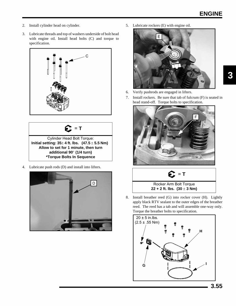
ENGINE
3
2. Install cylinder head on cylinder.
3. Lubricate threads and top of washers underside of bolt headwith engine oil. Install head bolts (C) and torque tospecification.
4. Lubricate push rods (D) and install into lifters.
5. Lubricate rockers (E) with engine oil.
6. Verify pushrods are engaged in lifters.7. Install rockers. Be sure that tab of fulcrum (F) is seated in
head stand-off. Torque bolts to specification.
8. Install breather reed (G) into rocker cover (H). Lightlyapply black RTV sealant to the outer edges of the breatherreed. The reed has a tab and will assemble one-way only.Torque the breather bolts to specification.
= T
Cylinder Head Bolt Torque: Initial setting: 35± 4 ft. lbs. (47.5 ± 5.5 Nm)
Allow to set for 1 minute, then turn additional 90° (1/4 turn)
*Torque Bolts In Sequence
C
D
= T
Rocker Arm Bolt Torque22 + 2 ft. lbs. (30 ± 3 Nm)
E
F
20 ± 5 in.lbs. (2.5 ± .55 Nm)
G
H
I
3.55

ENGINE
NOTE: When applying RTV, do not get any RTVinside the reed assembly.
9. Place a new seal (I) into the bottom of the cover. Be surethe seal is seated into the cover properly.
IMPORTANT: Before assembly, clean the bolts andbolt holes with Primer N (PN 2870585) to remove anydebris. This will ensure proper sealing wheninstalling bolts.
10. Install rocker cover. Torque bolts to specification.
11. Install thermostat (J), new O-ring, and thermostat housing.Torque to specification.
12. Install temperature sender (K) and torque to specification.
= T
Breather Bolt Toque:20 ± 5 in. lbs. (2.5± 0.55 Nm)
= T
Rocker Cover Bolt Torque: 84 ± 8 in.lbs. (9.5 ± 0.9 Nm)
Torque in Sequence
= T
Thermostat Housing Bolt Torque: 84 ± 8 in. lbs. (9.5± 0.9 Nm)
= T
Temperature Sender Torque:17 ± 2 ft.lbs. (23 ± 3 Nm)
J
17 ± 2 ft. lbs.(23 ± 3 Nm)
84 ± 8 in. lbs.(9.5 ± 0.9 Nm)
K
K
3.56
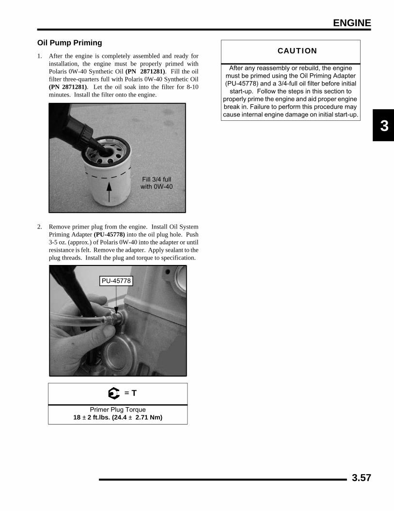
ENGINE
3
Oil Pump Priming1. After the engine is completely assembled and ready for
installation, the engine must be properly primed withPolaris 0W-40 Synthetic Oil (PN 2871281). Fill the oilfilter three-quarters full with Polaris 0W-40 Synthetic Oil(PN 2871281). Let the oil soak into the filter for 8-10minutes. Install the filter onto the engine.
2. Remove primer plug from the engine. Install Oil SystemPriming Adapter (PU-45778) into the oil plug hole. Push3-5 oz. (approx.) of Polaris 0W-40 into the adapter or untilresistance is felt. Remove the adapter. Apply sealant to theplug threads. Install the plug and torque to specification.
= T
Primer Plug Torque18 ± 2 ft.lbs. (24.4 ± 2.71 Nm)
Fill 3/4 fullwith 0W-40
PU-45778
CAUTION
After any reassembly or rebuild, the engine must be primed using the Oil Priming Adapter (PU-45778) and a 3/4-full oil filter before initial
start-up. Follow the steps in this section to properly prime the engine and aid proper engine break in. Failure to perform this procedure may cause internal engine damage on initial start-up.
3.57
ENGINE
TROUBLESHOOTINGEngine
Spark Plug Fouling• Spark plug cap loose or faulty
• Incorrect spark plug heat range or gap
• PVT system calibrated incorrectly/ components worn or mis-adjusted
• Fuel quality poor (old) or octane too high
• Low compression
• Restricted exhaust
• Weak ignition (loose coil ground, faulty coil, stator, or ETC switch)
• ETC switch mis-adjusted
• Restricted air filter (main or pre-cleaner) or breather system
• Improperly assembled air intake system
• Restricted engine breather system
• Oil contaminated with fuel
Engine Turns Over But Fails To Start• No fuel
• Dirt in fuel line or filter
• Fuel will not pass through fuel valve
• Fuel pump inoperative/restricted
• Tank vent plugged or pinched
• Engine flooded
• Low compression (high cylinder leakage)
• No spark (Spark plug fouled) ignition component failure
Engine Does Not Turn Over• Dead battery
• Starter motor does not turn
• Engine seized, rusted, or mechanical failure
Engine Runs But Will Not Idle• Restricted carburetor pilot system
• Low compression
• Crankcase breather restricted
Engine Idles But Will Not Accelerate
• Spark plug fouled/weak spark
• Broken throttle cable
• Obstruction in air intake
• Air box removed (reinstall all intake components)
• Incorrect or restricted carburetor jetting
• ETC switch limiting speed
• Reverse speed limiter limiting speed
• Incorrect ignition timing
• Restricted exhaust system
• Cam worn excessively
Engine Has Low Power• Spark plug fouled
• Cylinder, piston, ring, or valve wear or damage (check compression)
• PVT not operating properly
• Restricted exhaust muffler
• Cam worn excessively
Piston Failure - Scoring• Lack of lubrication
• Dirt entering engine through cracks in air filter or ducts
• Engine oil dirty or contaminated
Excessive Smoke and Carbon Buildup• Excessive piston-to-cylinder clearance
• Wet sumping
• Worn rings, piston, or cylinder
• Worn valve guides or seals
• Restricted breather
• Air filter dirty or contaminated
Piston Failure - Scoring
• Lack of lubrication
• Dirt entering engine through cracks in air filter or ducts
• Engine oil dirty or contaminated
3.58
ENGINE
3
Excessive Smoke and Carbon Buildup
• Excessive piston-to-cylinder clearance
• Wet sumping due to over-full crankcase
• Worn rings, piston, or cylinder
• Worn valve guides or seals
• Restricted breather
• Air filter dirty or contaminated
Low Compression• Cylinder head gasket leak
• No valve clearance ( cam wear )
• Cylinder or piston worn
• Piston rings worn, leaking, broken, or sticking
• Bent valve or stuck valve
• Valve spring broken or weak
• Valve not seating properly (bent or carbon accumulated on sealing surface)
• Rocker arm sticking
Backfiring• ETC or speed limiter system malfunction
• Fouled spark plug or incorrect plug or plug gap
• Exhaust system air leaks
• Exhaust system air leaks
• Ignition system faulty: Spark plug cap cracked / brokenIgnition coil faultyIgnition or kill switch circuit faultyPoor connections in ignition systemIgnition timing incorrectSheared flywheel key
• Valve sticking
Cooling System
Overheating
• Low coolant level
• Air in cooling system
• Wrong type/mix of coolant
• Faulty pressure cap or system leaks
• Restricted system (mud or debris in radiator fins causing restriction to air flow, passages blocked in radiator, lines, pump, or water jacket, accident damage)
• Lean mixture (restricted jets, vents, fuel pump or fuel valve)
• Fuel pump output weak
• Electrical malfunction
• Water pump failure/ Loose impeller
• Thermistor failure
• Cooling fan inoperative or turning too slowly (perform current draw test)
• Ignition timing mis-adjusted
• Low oil level
• Spark plug incorrect heat range
• Faulty hot light circuit
• Thermostat stuck closed or not opening completely
Temperature Too Low• Thermostat stuck open
Leak at Water Pump Weep Hole
• Faulty water pump mechanical seal (coolant leak)
• Faulty pump shaft oil seal (oil leak)
3.59
FUEL INJECTION
CHAPTER 4FUEL INJECTION
4
GENERAL INFORMATION . . . . . . . . . . . . . . . . . . . . . . . . . . . . . . . . . . . . . . . . . . . . . . . . 4.2SPECIAL TOOLS . . . . . . . . . . . . . . . . . . . . . . . . . . . . . . . . . . . . . . . . . . . . . . . . . . . . . . . 4.2SERVICE NOTES. . . . . . . . . . . . . . . . . . . . . . . . . . . . . . . . . . . . . . . . . . . . . . . . . . . . . . . 4.4EFI SYSTEM EXPLODED VIEW . . . . . . . . . . . . . . . . . . . . . . . . . . . . . . . . . . . . . . . . . . . 4.5EFI SYSTEM COMPONENT LOCATIONS . . . . . . . . . . . . . . . . . . . . . . . . . . . . . . . . . . . 4.6
FUEL TANK . . . . . . . . . . . . . . . . . . . . . . . . . . . . . . . . . . . . . . . . . . . . . . . . . . . . . . . . . . . . 4.8EXPLODED VIEW . . . . . . . . . . . . . . . . . . . . . . . . . . . . . . . . . . . . . . . . . . . . . . . . . . . . . . 4.8FUEL LINES - QUICK CONNECT . . . . . . . . . . . . . . . . . . . . . . . . . . . . . . . . . . . . . . . . . . 4.9
ELECTRONIC FUEL INJECTION . . . . . . . . . . . . . . . . . . . . . . . . . . . . . . . . . . . . . . . . . . . 4.9PRINCIPAL COMPONENTS . . . . . . . . . . . . . . . . . . . . . . . . . . . . . . . . . . . . . . . . . . . . . . 4.9EFI OPERATION OVERVIEW . . . . . . . . . . . . . . . . . . . . . . . . . . . . . . . . . . . . . . . . . . . . . 4.9INITIAL PRIMING / STARTING PROCEDURE . . . . . . . . . . . . . . . . . . . . . . . . . . . . . . . 4.10
ELECTRONIC CONTROL UNIT (ECU). . . . . . . . . . . . . . . . . . . . . . . . . . . . . . . . . . . . . . 4.10OPERATION OVERVIEW . . . . . . . . . . . . . . . . . . . . . . . . . . . . . . . . . . . . . . . . . . . . . . . 4.10ECU SERVICE . . . . . . . . . . . . . . . . . . . . . . . . . . . . . . . . . . . . . . . . . . . . . . . . . . . . . . . . 4.11ECU REPLACEMENT . . . . . . . . . . . . . . . . . . . . . . . . . . . . . . . . . . . . . . . . . . . . . . . . . . 4.11
FUEL PUMP . . . . . . . . . . . . . . . . . . . . . . . . . . . . . . . . . . . . . . . . . . . . . . . . . . . . . . . . . . 4.11OPERATION OVERVIEW . . . . . . . . . . . . . . . . . . . . . . . . . . . . . . . . . . . . . . . . . . . . . . . 4.11FUEL PUMP TEST . . . . . . . . . . . . . . . . . . . . . . . . . . . . . . . . . . . . . . . . . . . . . . . . . . . . . 4.12FUEL PUMP / TANK ASSEMBLY REPLACEMENT . . . . . . . . . . . . . . . . . . . . . . . . . . . 4.12
FUEL PRESSURE REGULATOR . . . . . . . . . . . . . . . . . . . . . . . . . . . . . . . . . . . . . . . . . . 4.14OPERATION OVERVIEW . . . . . . . . . . . . . . . . . . . . . . . . . . . . . . . . . . . . . . . . . . . . . . . 4.14FUEL PRESSURE REGULATOR TEST . . . . . . . . . . . . . . . . . . . . . . . . . . . . . . . . . . . . 4.14FUEL PRESSURE REGULATOR REPLACEMENT. . . . . . . . . . . . . . . . . . . . . . . . . . . . 4.14
FUEL INJECTORS . . . . . . . . . . . . . . . . . . . . . . . . . . . . . . . . . . . . . . . . . . . . . . . . . . . . . 4.14OPERATION OVERVIEW . . . . . . . . . . . . . . . . . . . . . . . . . . . . . . . . . . . . . . . . . . . . . . . 4.14FUEL INJECTOR SERVICE. . . . . . . . . . . . . . . . . . . . . . . . . . . . . . . . . . . . . . . . . . . . . . 4.15FUEL INJECTOR REPLACEMENT . . . . . . . . . . . . . . . . . . . . . . . . . . . . . . . . . . . . . . . . 4.15
CRANKSHAFT POSITION SENSOR (CPS) . . . . . . . . . . . . . . . . . . . . . . . . . . . . . . . . . . 4.15OPERATION OVERVIEW . . . . . . . . . . . . . . . . . . . . . . . . . . . . . . . . . . . . . . . . . . . . . . . 4.15CPS TEST . . . . . . . . . . . . . . . . . . . . . . . . . . . . . . . . . . . . . . . . . . . . . . . . . . . . . . . . . . . 4.16CPS REPLACEMENT. . . . . . . . . . . . . . . . . . . . . . . . . . . . . . . . . . . . . . . . . . . . . . . . . . . 4.16
TEMPERATURE / BAROMETRIC AIR PRESSURE SENSOR (T-BAP). . . . . . . . . . . . . 4.16OPERATION OVERVIEW . . . . . . . . . . . . . . . . . . . . . . . . . . . . . . . . . . . . . . . . . . . . . . . 4.16T-BAP TEST . . . . . . . . . . . . . . . . . . . . . . . . . . . . . . . . . . . . . . . . . . . . . . . . . . . . . . . . . . 4.16T-BAP REPLACEMENT . . . . . . . . . . . . . . . . . . . . . . . . . . . . . . . . . . . . . . . . . . . . . . . . . 4.16
THROTTLE POSITION SENSOR (TPS) . . . . . . . . . . . . . . . . . . . . . . . . . . . . . . . . . . . . . 4.17OPERATION OVERVIEW . . . . . . . . . . . . . . . . . . . . . . . . . . . . . . . . . . . . . . . . . . . . . . . 4.17TPS TEST. . . . . . . . . . . . . . . . . . . . . . . . . . . . . . . . . . . . . . . . . . . . . . . . . . . . . . . . . . . . 4.17TPS INITIALIZATION . . . . . . . . . . . . . . . . . . . . . . . . . . . . . . . . . . . . . . . . . . . . . . . . . . . 4.18TPS REPLACEMENT. . . . . . . . . . . . . . . . . . . . . . . . . . . . . . . . . . . . . . . . . . . . . . . . . . . 4.19
ENGINE COOLANT TEMPERATURE SENSOR (ECT) . . . . . . . . . . . . . . . . . . . . . . . . . 4.19OPERATION OVERVIEW . . . . . . . . . . . . . . . . . . . . . . . . . . . . . . . . . . . . . . . . . . . . . . . 4.19ECT SENSOR TEST . . . . . . . . . . . . . . . . . . . . . . . . . . . . . . . . . . . . . . . . . . . . . . . . . . . 4.20ECT SENSOR REPLACEMENT. . . . . . . . . . . . . . . . . . . . . . . . . . . . . . . . . . . . . . . . . . . 4.20
GENERAL TROUBLESHOOTING. . . . . . . . . . . . . . . . . . . . . . . . . . . . . . . . . . . . . . . . . . 4.21DIAGNOSTIC “BLINK CODES” . . . . . . . . . . . . . . . . . . . . . . . . . . . . . . . . . . . . . . . . . . . 4.21EFI TROUBLESHOOTING . . . . . . . . . . . . . . . . . . . . . . . . . . . . . . . . . . . . . . . . . . . . . . . 4.22
4.1
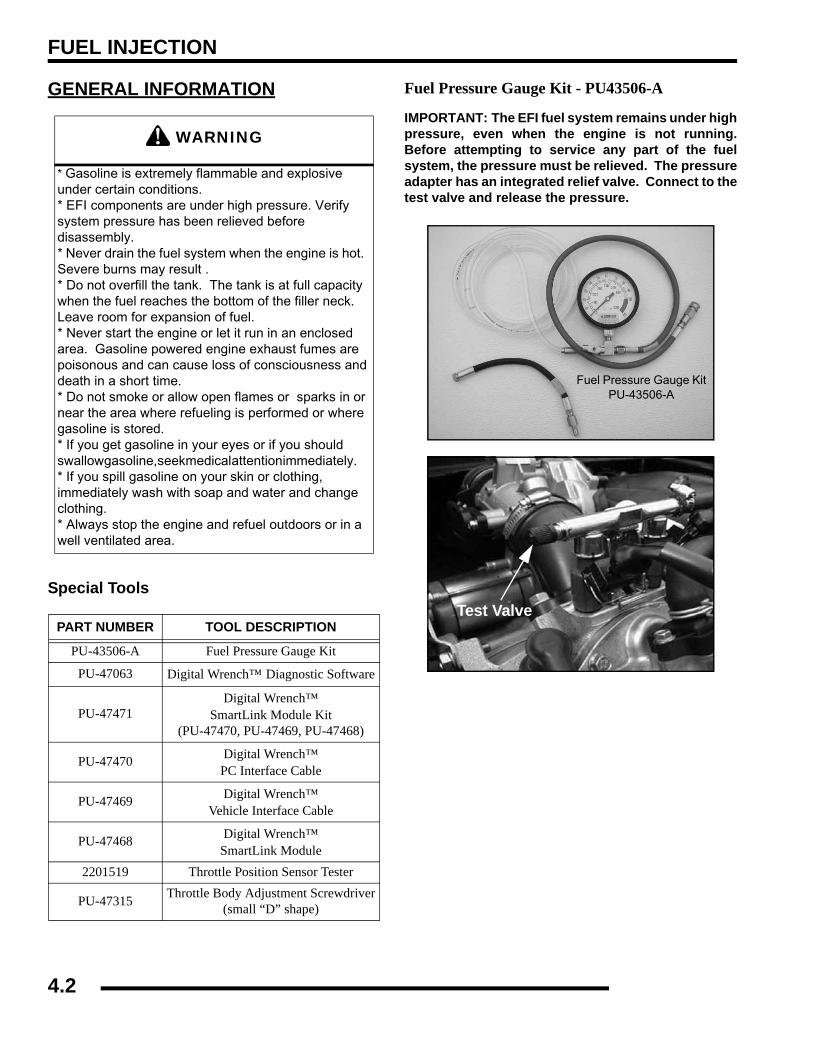
FUEL INJECTION
GENERAL INFORMATION
Special Tools
Fuel Pressure Gauge Kit - PU43506-A
IMPORTANT: The EFI fuel system remains under highpressure, even when the engine is not running.Before attempting to service any part of the fuelsystem, the pressure must be relieved. The pressureadapter has an integrated relief valve. Connect to thetest valve and release the pressure.
WARNING
* Gasoline is extremely flammable and explosive under certain conditions.* EFI components are under high pressure. Verify system pressure has been relieved before disassembly.* Never drain the fuel system when the engine is hot. Severe burns may result .* Do not overfill the tank. The tank is at full capacity when the fuel reaches the bottom of the filler neck. Leave room for expansion of fuel.* Never start the engine or let it run in an enclosed area. Gasoline powered engine exhaust fumes are poisonous and can cause loss of consciousness and death in a short time.* Do not smoke or allow open flames or sparks in or near the area where refueling is performed or where gasoline is stored. * If you get gasoline in your eyes or if you should swallow gasoline, seek medical attention immediately. * If you spill gasoline on your skin or clothing, immediately wash with soap and water and change clothing. * Always stop the engine and refuel outdoors or in a well ventilated area.
PART NUMBER TOOL DESCRIPTION
PU-43506-A Fuel Pressure Gauge Kit
PU-47063 Digital Wrench™ Diagnostic Software
PU-47471Digital Wrench™
SmartLink Module Kit(PU-47470, PU-47469, PU-47468)
PU-47470 Digital Wrench™PC Interface Cable
PU-47469 Digital Wrench™Vehicle Interface Cable
PU-47468 Digital Wrench™SmartLink Module
2201519 Throttle Position Sensor Tester
PU-47315 Throttle Body Adjustment Screwdriver(small “D” shape)
Fuel Pressure Gauge KitPU-43506-A
Test Valve
4.2

FUEL INJECTION
4
Digital Wrench™ Diagnostic Software - PU-47063This dealer-only software installs on laptop computers equippedwith a CD drive and serial port connection, and is designed toreplace multiple shop tools often used to test EFI components.It also includes step-by-step diagnostic procedures to aidtechnician repair and troubleshooting.
Digital Wrench™SmartLink Module Kit - PU-47471This module kit contains the necessary cables and hardware tocommunicate between the vehicle ECU and the DigitalWrench™ diagnostic software. Polaris dealers can also orderthe following separately: SmartLink Module PU-47468,Vehicle Interface Cable PU-47469 and PC Interface CablePU-47470. This module kit is used on all 8 pin connector-basedPolaris EFI systems. This kit is available to Polaris dealersthrough our tool supplier, SPX (1-800-328-6657).
Digital Wrench™ - Diagnostic Connector(Located under the hood as shown below)
Throttle Position Sensor Tester - PU-47082
This tester allows the use of a digital multi-meter to test TPSfunction as well perform initialization procedures.
Throttle Body Adjustment ScrewdriverPU-47315This tool has a special ‘D’ shaped end for adjusting the throttlestop screw during a TPS initialization procedure.
PU-47468
PU-47469
PU-47470
4.3
FUEL INJECTION
Service Notes
• For more convenient and accurate testing of EFI components, it is recommended dealers utilize the Digital Wrench™ Diagnostic Software (dealer only), or testing may be done manually using the procedures provided.
• 80% of all EFI problems are caused by wiring harness connections.
• For the purpose of troubleshooting difficult running issues, a known-good ECU from another Polaris RANGER XP EFI of the same model may be used without damaging system or engine components.
• Never attempt to service any fuel system component while engine is running or ignition switch is "on."
• Cleanliness is essential and must be maintained at all times when servicing or working on the EFI system. Dirt, even in small quantities, can cause significant problems.
• Do not use compressed air if the system is open. Cover any parts removed and wrap any open joints with plastic if they will remain open for any length of time. New parts should be removed from their protective packaging just prior to installation.
• Clean any connector before opening to prevent dirt from entering the system.
• Although every precaution has been taken to prevent water intrusion failure, avoid direct water or spray contact with system components.
• Do not disconnect or reconnect the wiring harness connector to the control unit or any individual components with the ignition "on." This can send a damaging voltage spike through the ECU.
• Do not allow the battery cables to touch opposing terminals. When connecting battery cables attach the positive (+) cable to positive (+) battery terminal first, followed by negative (-) cable to negative (-) battery terminal.
• Never start the engine when the cables are loose or poorly connected to the battery terminals.
• Never disconnect battery while engine is running.
• Never use a battery boost-pack to start the engine.
• Do not charge battery with key switch "on."
• Always disconnect negative (-) battery cable lead before charging battery.
• Always unplug ECU from the wire harness before performing any welding on the unit.
4.4
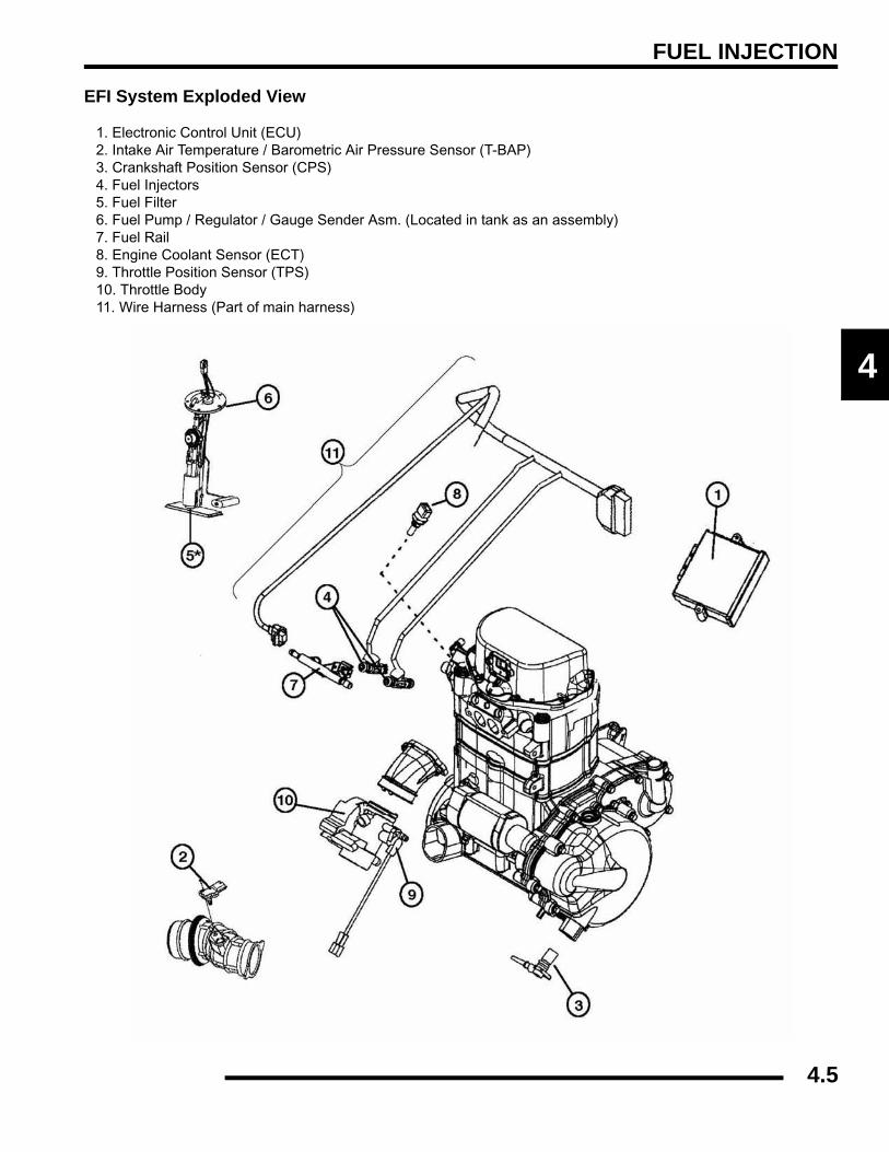
FUEL INJECTION
4
EFI System Exploded View
1. Electronic Control Unit (ECU) 2. Intake Air Temperature / Barometric Air Pressure Sensor (T-BAP) 3. Crankshaft Position Sensor (CPS) 4. Fuel Injectors 5. Fuel Filter 6. Fuel Pump / Regulator / Gauge Sender Asm. (Located in tank as an assembly) 7. Fuel Rail 8. Engine Coolant Sensor (ECT) 9. Throttle Position Sensor (TPS) 10. Throttle Body11. Wire Harness (Part of main harness)
4.5
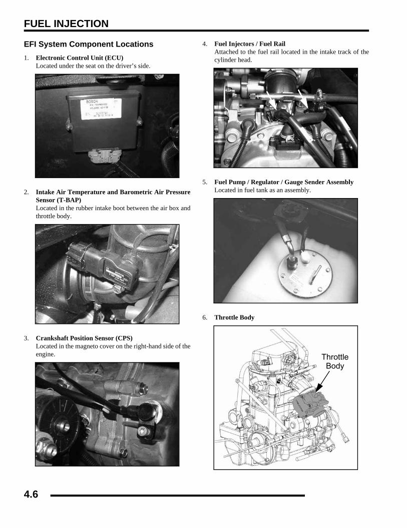
FUEL INJECTION
EFI System Component Locations1. Electronic Control Unit (ECU)
Located under the seat on the driver’s side.
2. Intake Air Temperature and Barometric Air PressureSensor (T-BAP)Located in the rubber intake boot between the air box andthrottle body.
3. Crankshaft Position Sensor (CPS)Located in the magneto cover on the right-hand side of theengine.
4. Fuel Injectors / Fuel RailAttached to the fuel rail located in the intake track of thecylinder head.
5. Fuel Pump / Regulator / Gauge Sender AssemblyLocated in fuel tank as an assembly.
6. Throttle Body
ThrottleBody
4.6
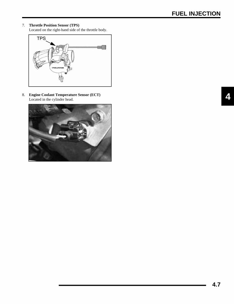
FUEL INJECTION
4
7. Throttle Position Sensor (TPS)Located on the right-hand side of the throttle body.
8. Engine Coolant Temperature Sensor (ECT)Located in the cylinder head.
TPS
4.7
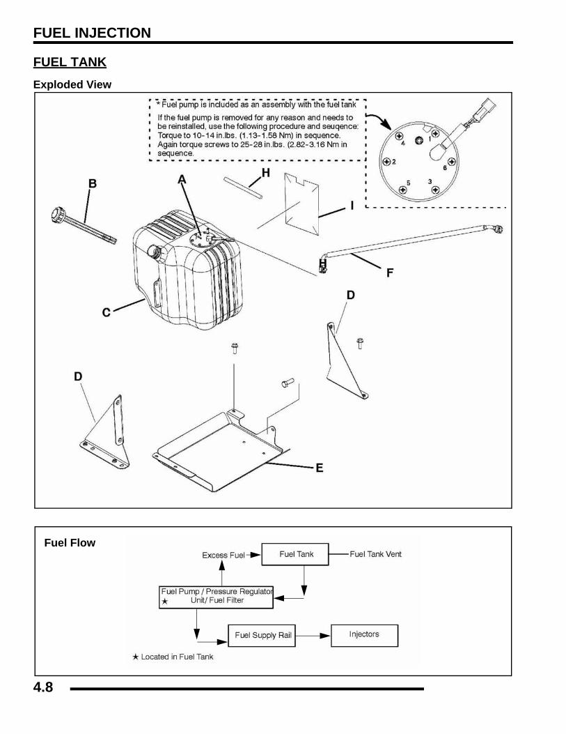
FUEL INJECTION
FUEL TANKExploded View
Fuel Flow
4.8
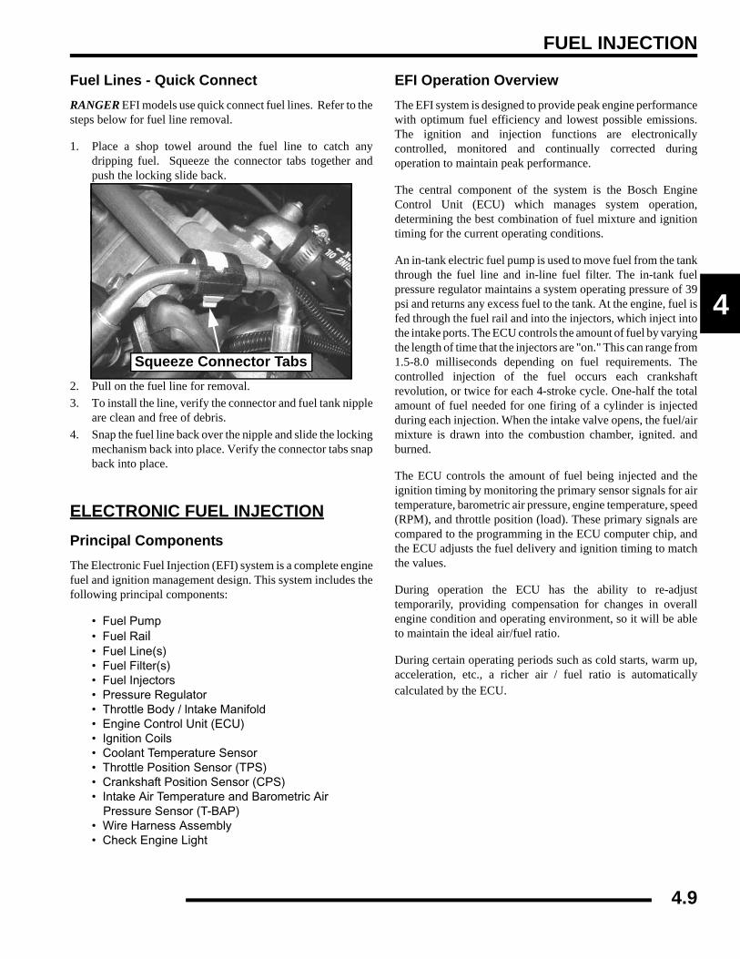
FUEL INJECTION
4
Fuel Lines - Quick ConnectRANGER EFI models use quick connect fuel lines. Refer to thesteps below for fuel line removal.
1. Place a shop towel around the fuel line to catch anydripping fuel. Squeeze the connector tabs together andpush the locking slide back.
2. Pull on the fuel line for removal.3. To install the line, verify the connector and fuel tank nipple
are clean and free of debris.4. Snap the fuel line back over the nipple and slide the locking
mechanism back into place. Verify the connector tabs snapback into place.
ELECTRONIC FUEL INJECTIONPrincipal ComponentsThe Electronic Fuel Injection (EFI) system is a complete enginefuel and ignition management design. This system includes thefollowing principal components:
• Fuel Pump• Fuel Rail• Fuel Line(s)• Fuel Filter(s)• Fuel Injectors• Pressure Regulator• Throttle Body / lntake Manifold• Engine Control Unit (ECU)• Ignition Coils• Coolant Temperature Sensor• Throttle Position Sensor (TPS)• Crankshaft Position Sensor (CPS)• Intake Air Temperature and Barometric Air
Pressure Sensor (T-BAP)• Wire Harness Assembly• Check Engine Light
EFI Operation OverviewThe EFI system is designed to provide peak engine performancewith optimum fuel efficiency and lowest possible emissions.The ignition and injection functions are electronicallycontrolled, monitored and continually corrected duringoperation to maintain peak performance.
The central component of the system is the Bosch EngineControl Unit (ECU) which manages system operation,determining the best combination of fuel mixture and ignitiontiming for the current operating conditions.
An in-tank electric fuel pump is used to move fuel from the tankthrough the fuel line and in-line fuel filter. The in-tank fuelpressure regulator maintains a system operating pressure of 39psi and returns any excess fuel to the tank. At the engine, fuel isfed through the fuel rail and into the injectors, which inject intothe intake ports. The ECU controls the amount of fuel by varyingthe length of time that the injectors are "on." This can range from1.5-8.0 milliseconds depending on fuel requirements. Thecontrolled injection of the fuel occurs each crankshaftrevolution, or twice for each 4-stroke cycle. One-half the totalamount of fuel needed for one firing of a cylinder is injectedduring each injection. When the intake valve opens, the fuel/airmixture is drawn into the combustion chamber, ignited. andburned.
The ECU controls the amount of fuel being injected and theignition timing by monitoring the primary sensor signals for airtemperature, barometric air pressure, engine temperature, speed(RPM), and throttle position (load). These primary signals arecompared to the programming in the ECU computer chip, andthe ECU adjusts the fuel delivery and ignition timing to matchthe values.
During operation the ECU has the ability to re-adjusttemporarily, providing compensation for changes in overallengine condition and operating environment, so it will be ableto maintain the ideal air/fuel ratio.
During certain operating periods such as cold starts, warm up,acceleration, etc., a richer air / fuel ratio is automaticallycalculated by the ECU.
Squeeze Connector Tabs
4.9

FUEL INJECTION
Initial Priming / Starting ProcedureNOTE: The Injection system must be purged of allair prior to the initial start up, and / or any time thesystem has been disassembled.
If the EFI system is completely empty of fuel or has beendisassembled and repaired:
1. Cycle the key switch from “OFF” to “ON” 6 times,waiting for approximately 3 seconds at each “ON” cycle toallow the fuel pump to cycle and shut down.
2. Once step 1 is completed, turn the key switch to “START”until the engine starts or 5 seconds has passed.
3. If the engine failed to start, repeat step 1 for 2 more cyclesand attempt to start the engine.
If the engine fails to start, a problem may still exist, and shouldbe diagnosed.
NOTE: Accurate testing of EFI components isrecommended utilizing the Digital Wrench™Diagnostic Software (dealer only).
ELECTRONIC CONTROL UNIT (ECU)Operation OverviewThe ECU is the brain or central processing computer of theentire EFI fuel/ignition management system. During operation,sensors continuously gather data which is relayed through thewiring harness to input circuits within the ECU. Signals to theECU include: ignition (on/off), crankshaft position and speed(RPM), throttle position, engine coolant temperature, airtemperature, intake manifold air pressure and battery voltage.The ECU compares the input signals to the programmed mapsin its memory and determines the appropriate fuel and sparkrequirements for the immediate operating conditions. The ECUthen sends output signals to set the injector duration and ignitiontiming.
During operation, the ECU continually performs a diagnosticcheck of itself, each of the sensors, and system performance. Ifa fault is detected, the ECU turns on the “Check Engine” lightin the speedometer and stores the fault code in its fault memory.Depending on the significance or severity of the fault, normaloperation may continue, or "Fail-Safe" operation (slowed speed,richer running) may be initiated. A technician can determine thecause of the “Check Engine” light by initiating the “Blink Code”sequence or by using Digital Wrench™. The ECU requires aminimum of 7.0 volts to operate. The memory in the ECU isoperational the moment the battery cables are connected.
To prevent engine over-speed and possible failure, a rev-limiting feature is programmed into the ECU. If the maximumRPM limit (6200) is exceeded, the ECU suppresses the injectionsignals, cutting off the fuel flow. This process repeats it self inrapid succession, limiting operation to the preset maximum.
4.10
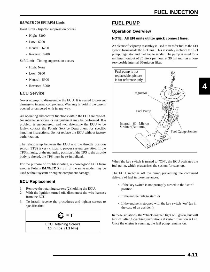
FUEL INJECTION
4
RANGER 700 EFI RPM Limit:
Hard Limit - Injector suppression occurs
• High: 6200
• Low: 6200
• Neutral: 6200
• Reverse: 6200
Soft Limit - Timing suppression occurs
• High: None
• Low: 5900
• Neutral: 5900
• Reverse: 5900
ECU ServiceNever attempt to disassemble the ECU. It is sealed to preventdamage to internal components. Warranty is void if the case isopened or tampered with in any way.
All operating and control functions within the ECU are pre-set.No internal servicing or readjustment may be performed. If aproblem is encountered, and you determine the ECU to befaulty, contact the Polaris Service Department for specifichandling instructions. Do not replace the ECU without factoryauthorization.
The relationship between the ECU and the throttle positionsensor (TPS) is very critical to proper system operation. If theTPS is faulty, or the mounting position of the TPS to the throttlebody is altered, the TPS must be re-initialized.
For the purpose of troubleshooting, a known-good ECU fromanother Polaris RANGER XP EFI of the same model may beused without system or engine component damage.
ECU Replacement1. Remove the retaining screws (2) holding the ECU.2. With the Ignition turned off, disconnect the wire harness
from the ECU.3. To install, reverse the procedures and tighten screws to
specification.
FUEL PUMPOperation OverviewNOTE: All EFI units utilize quick connect lines.
An electric fuel pump assembly is used to transfer fuel to the EFIsystem from inside the fuel tank. This assembly includes the fuelpump, regulator and fuel gauge sender. The pump is rated for aminimum output of 25 liters per hour at 39 psi and has a non-serviceable internal 60-micron filter.
When the key switch is turned to "ON", the ECU activates thefuel pump, which pressurizes the system for start-up.
The ECU switches off the pump preventing the continueddelivery of fuel in these instances:
• If the key switch is not promptly turned to the "start" position.
• If the engine fails to start, or
• If the engine is stopped with the key switch "on" (as in the case of an accident)
In these situations, the “check engine” light will go on, but willturn off after 4 cranking revolutions if system function is OK.Once the engine is running, the fuel pump remains on.
= T
ECU Retaining Screws10 in. lbs. (1.1 Nm)
Fuel pump is not replaceable, picture is for reference only.
Regulator
Fuel Pump
Internal 60 MicronStrainer (Bottom)
Fuel Gauge Sender
4.11

FUEL INJECTION
Fuel Pump TestNOTE: FUEL GAUGE SENDER TEST - To test fuelgauge sender function, refer to Chapter 10.
The fuel pump/tank assembly is non-serviceable and must bereplaced if determined to be faulty. If a fuel delivery problem issuspected, make certain the filters are not plugged, that thepump is being activated through the ECU, all electricalconnections are properly secured, the fuses are good, and aminimum of 7.0 volts is being supplied. If during starting thebattery voltage drops below 7.0 volts, the ECU will fail tooperate the system.
1. Remove the cap from the fuel test valve.
2. Connect the pressure hose of the Polaris pressure tester(PN PU-43506) to the test valve on the fuel rail. Route theclear hose into a portable gasoline container or theequipment fuel tank.
3. Turn on the key switch to activate the pump and check thesystem pressure on the gauge. If system pressure of 39 psi± 3 is observed, the ignition switch, ECU, fuel pump, andpressure regulator are working properly. Turn the keyswitch off and depress the valve button on the tester torelieve the system pressure.
NOTE: If the pressure is too high or too low, replacethe fuel tank assembly.
4. If the pump did not activate (Step 2), disconnect the plugfrom the fuel pump. Connect a DC voltmeter acrossterminals “A” and “C” in the plug, turn on the key switchand observe if a minimum of 7 volts is present. If voltageis between 7 and 14, turn key switch off and connect anohmmeter between the terminals “A” and “C”' on the pumpto check for continuity.
NOTE: If there was no continuity between the pumpterminals, replace the fuel tank assembly.
NOTE: If the voltage was below 7Vdc, test thebattery, ignition switch, wiring harness and ECU.
5. If voltage at the plug was good, and there was continuityacross the pump terminals, reconnect the plug to the pump,making sure you have good, clean connections. Turn on thekey switch and listen for the pump to activate.
NOTE: If the pump starts, repeat steps 1 and 2 toverify correct pressure.
NOTE: If the pump still does not operate, check forcorrect ECU operation by plugging in a known-goodECU of the same model.
NOTE: If the pump still does not operate, replace thepump/tank assembly.
Fuel Pump / Tank Assembly ReplacementNOTE: All EFI units utilize quick connect fuel lines.
NOTE: The fuel pump cannot be replaced as anindividual part, the entire fuel pump and fuel tank isreplaced as an assembly. Refer to your parts bookfor the proper part number.
WARNING
Check the fuel test valve for any possible fuel seepage after performing any tests or
procedures. Fuel is extremely flammable and may cause severe burns, injury, or death.
Do not use any device that produces a flame or electrical devices that may spark around
fuel or fuel vapors.
Normal Fuel Pressure: 39 psi. ± 3
WARNING
Always wear safety goggles when working with high pressure or flammable fluids. Failure to do so
could result in serious injury or complications.
4.12
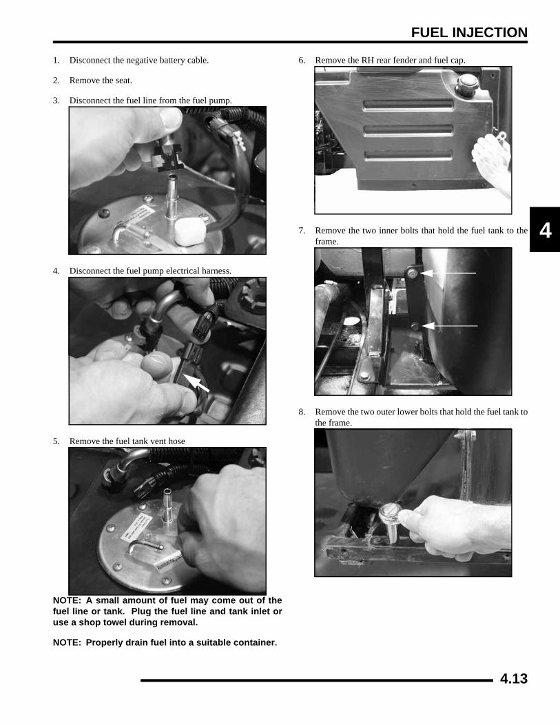
FUEL INJECTION
4
1. Disconnect the negative battery cable.
2. Remove the seat.
3. Disconnect the fuel line from the fuel pump.
4. Disconnect the fuel pump electrical harness.
5. Remove the fuel tank vent hose
NOTE: A small amount of fuel may come out of thefuel line or tank. Plug the fuel line and tank inlet oruse a shop towel during removal.
NOTE: Properly drain fuel into a suitable container.
6. Remove the RH rear fender and fuel cap.
7. Remove the two inner bolts that hold the fuel tank to theframe.
8. Remove the two outer lower bolts that hold the fuel tank tothe frame.
4.13
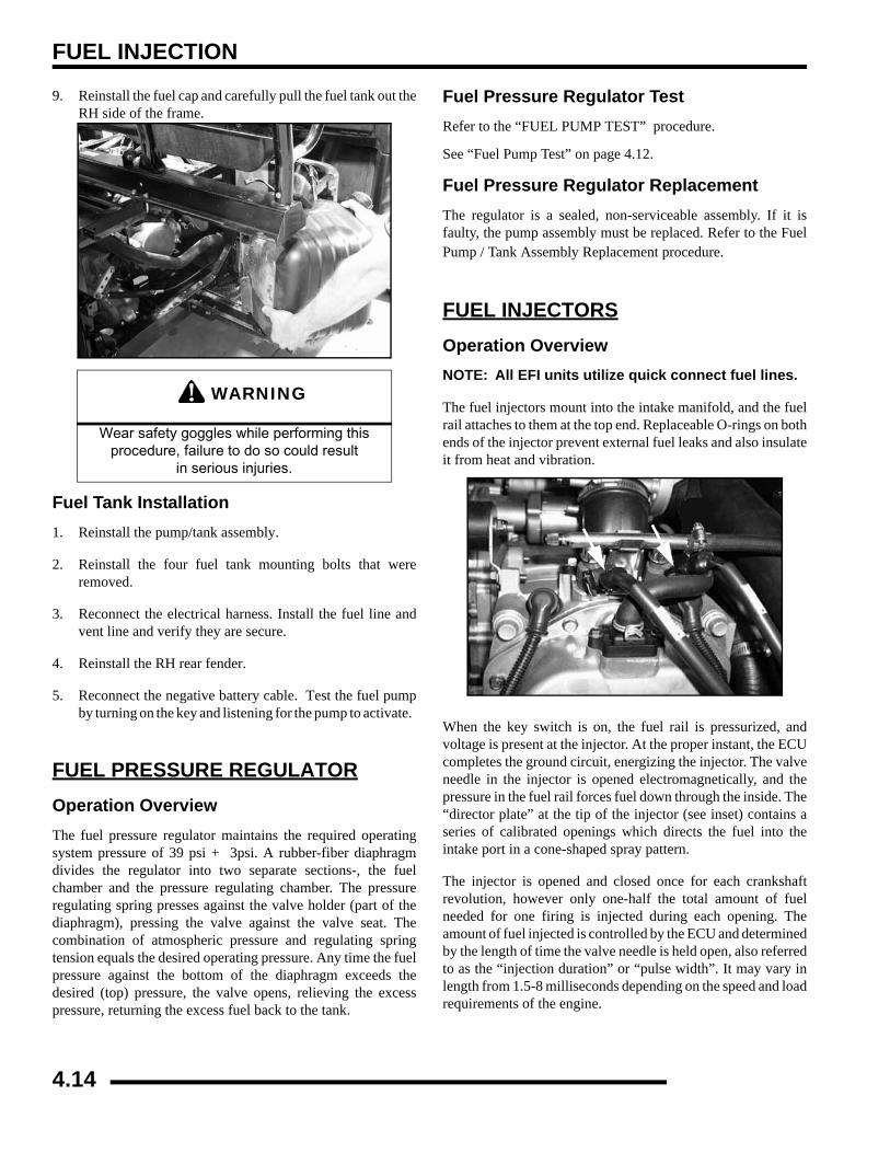
FUEL INJECTION
9. Reinstall the fuel cap and carefully pull the fuel tank out theRH side of the frame.
Fuel Tank Installation1. Reinstall the pump/tank assembly.
2. Reinstall the four fuel tank mounting bolts that wereremoved.
3. Reconnect the electrical harness. Install the fuel line andvent line and verify they are secure.
4. Reinstall the RH rear fender.
5. Reconnect the negative battery cable. Test the fuel pumpby turning on the key and listening for the pump to activate.
FUEL PRESSURE REGULATOROperation OverviewThe fuel pressure regulator maintains the required operatingsystem pressure of 39 psi + 3psi. A rubber-fiber diaphragmdivides the regulator into two separate sections-, the fuelchamber and the pressure regulating chamber. The pressureregulating spring presses against the valve holder (part of thediaphragm), pressing the valve against the valve seat. Thecombination of atmospheric pressure and regulating springtension equals the desired operating pressure. Any time the fuelpressure against the bottom of the diaphragm exceeds thedesired (top) pressure, the valve opens, relieving the excesspressure, returning the excess fuel back to the tank.
Fuel Pressure Regulator TestRefer to the “FUEL PUMP TEST” procedure.
See “Fuel Pump Test” on page 4.12.
Fuel Pressure Regulator ReplacementThe regulator is a sealed, non-serviceable assembly. If it isfaulty, the pump assembly must be replaced. Refer to the FuelPump / Tank Assembly Replacement procedure.
FUEL INJECTORSOperation OverviewNOTE: All EFI units utilize quick connect fuel lines.
The fuel injectors mount into the intake manifold, and the fuelrail attaches to them at the top end. Replaceable O-rings on bothends of the injector prevent external fuel leaks and also insulateit from heat and vibration.
When the key switch is on, the fuel rail is pressurized, andvoltage is present at the injector. At the proper instant, the ECUcompletes the ground circuit, energizing the injector. The valveneedle in the injector is opened electromagnetically, and thepressure in the fuel rail forces fuel down through the inside. The“director plate” at the tip of the injector (see inset) contains aseries of calibrated openings which directs the fuel into theintake port in a cone-shaped spray pattern.
The injector is opened and closed once for each crankshaftrevolution, however only one-half the total amount of fuelneeded for one firing is injected during each opening. Theamount of fuel injected is controlled by the ECU and determinedby the length of time the valve needle is held open, also referredto as the “injection duration” or “pulse width”. It may vary inlength from 1.5-8 milliseconds depending on the speed and loadrequirements of the engine.
WARNING
Wear safety goggles while performing this procedure, failure to do so could result
in serious injuries.
4.14
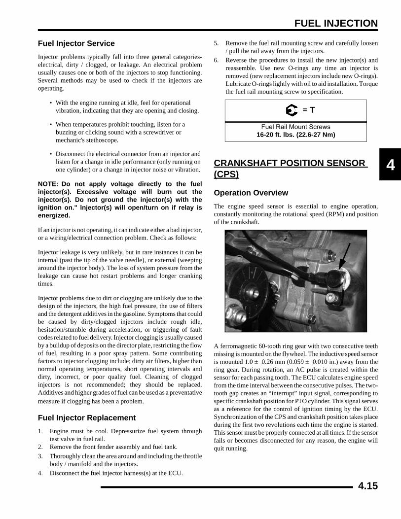
FUEL INJECTION
4
Fuel Injector ServiceInjector problems typically fall into three general categories-electrical, dirty / clogged, or leakage. An electrical problemusually causes one or both of the injectors to stop functioning.Several methods may be used to check if the injectors areoperating.
• With the engine running at idle, feel for operational vibration, indicating that they are opening and closing.
• When temperatures prohibit touching, listen for a buzzing or clicking sound with a screwdriver or mechanic's stethoscope.
• Disconnect the electrical connector from an injector and listen for a change in idle performance (only running on one cylinder) or a change in injector noise or vibration.
NOTE: Do not apply voltage directly to the fuelinjector(s). Excessive voltage will burn out theinjector(s). Do not ground the injector(s) with theignition on." lnjector(s) will open/turn on if relay isenergized.
If an injector is not operating, it can indicate either a bad injector,or a wiring/electrical connection problem. Check as follows:
Injector leakage is very unlikely, but in rare instances it can beinternal (past the tip of the valve needle), or external (weepingaround the injector body). The loss of system pressure from theleakage can cause hot restart problems and longer crankingtimes.
Injector problems due to dirt or clogging are unlikely due to thedesign of the injectors, the high fuel pressure, the use of filtersand the detergent additives in the gasoline. Symptoms that couldbe caused by dirty/clogged injectors include rough idle,hesitation/stumble during acceleration, or triggering of faultcodes related to fuel delivery. Injector clogging is usually causedby a buildup of deposits on the director plate, restricting the flowof fuel, resulting in a poor spray pattern. Some contributingfactors to injector clogging include; dirty air filters, higher thannormal operating temperatures, short operating intervals anddirty, incorrect, or poor quality fuel. Cleaning of cloggedinjectors is not recommended; they should be replaced.Additives and higher grades of fuel can be used as a preventativemeasure if clogging has been a problem.
Fuel Injector Replacement1. Engine must be cool. Depressurize fuel system through
test valve in fuel rail.2. Remove the front fender assembly and fuel tank.3. Thoroughly clean the area around and including the throttle
body / manifold and the injectors.4. Disconnect the fuel injector harness(s) at the ECU.
5. Remove the fuel rail mounting screw and carefully loosen/ pull the rail away from the injectors.
6. Reverse the procedures to install the new injector(s) andreassemble. Use new O-rings any time an injector isremoved (new replacement injectors include new O-rings).Lubricate O-rings lightly with oil to aid installation. Torquethe fuel rail mounting screw to specification.
CRANKSHAFT POSITION SENSOR (CPS)
Operation OverviewThe engine speed sensor is essential to engine operation,constantly monitoring the rotational speed (RPM) and positionof the crankshaft.
A ferromagnetic 60-tooth ring gear with two consecutive teethmissing is mounted on the flywheel. The inductive speed sensoris mounted 1.0 ± 0.26 mm (0.059 ± 0.010 in.) away from thering gear. During rotation, an AC pulse is created within thesensor for each passing tooth. The ECU calculates engine speedfrom the time interval between the consecutive pulses. The two-tooth gap creates an “interrupt” input signal, corresponding tospecific crankshaft position for PTO cylinder. This signal servesas a reference for the control of ignition timing by the ECU.Synchronization of the CPS and crankshaft position takes placeduring the first two revolutions each time the engine is started.This sensor must be properly connected at all times. If the sensorfails or becomes disconnected for any reason, the engine willquit running.
= T
Fuel Rail Mount Screws16-20 ft. lbs. (22.6-27 Nm)
4.15
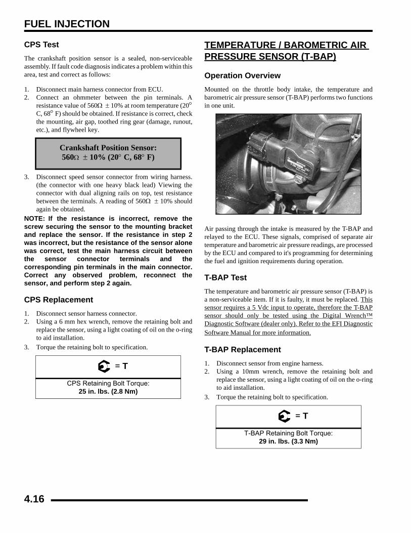
FUEL INJECTION
CPS TestThe crankshaft position sensor is a sealed, non-serviceableassembly. If fault code diagnosis indicates a problem within thisarea, test and correct as follows:
1. Disconnect main harness connector from ECU.2. Connect an ohmmeter between the pin terminals. A
resistance value of 560Ω ± 10% at room temperature (20°C, 68° F) should be obtained. If resistance is correct, checkthe mounting, air gap, toothed ring gear (damage, runout,etc.), and flywheel key.
3. Disconnect speed sensor connector from wiring harness.(the connector with one heavy black lead) Viewing theconnector with dual aligning rails on top, test resistancebetween the terminals. A reading of 560Ω ± 10% shouldagain be obtained.
NOTE: If the resistance is incorrect, remove thescrew securing the sensor to the mounting bracketand replace the sensor. If the resistance in step 2was incorrect, but the resistance of the sensor alonewas correct, test the main harness circuit betweenthe sensor connector terminals and thecorresponding pin terminals in the main connector.Correct any observed problem, reconnect thesensor, and perform step 2 again.
CPS Replacement1. Disconnect sensor harness connector.2. Using a 6 mm hex wrench, remove the retaining bolt and
replace the sensor, using a light coating of oil on the o-ringto aid installation.
3. Torque the retaining bolt to specification.
TEMPERATURE / BAROMETRIC AIR PRESSURE SENSOR (T-BAP)
Operation OverviewMounted on the throttle body intake, the temperature andbarometric air pressure sensor (T-BAP) performs two functionsin one unit.
Air passing through the intake is measured by the T-BAP andrelayed to the ECU. These signals, comprised of separate airtemperature and barometric air pressure readings, are processedby the ECU and compared to it's programming for determiningthe fuel and ignition requirements during operation.
T-BAP TestThe temperature and barometric air pressure sensor (T-BAP) isa non-serviceable item. If it is faulty, it must be replaced. Thissensor requires a 5 Vdc input to operate, therefore the T-BAPsensor should only be tested using the Digital Wrench™Diagnostic Software (dealer only). Refer to the EFI DiagnosticSoftware Manual for more information.
T-BAP Replacement1. Disconnect sensor from engine harness.2. Using a 10mm wrench, remove the retaining bolt and
replace the sensor, using a light coating of oil on the o-ringto aid installation.
3. Torque the retaining bolt to specification.
Crankshaft Position Sensor:560Ω ± 10% (20° C, 68° F)
= T
CPS Retaining Bolt Torque:25 in. lbs. (2.8 Nm)
= T
T-BAP Retaining Bolt Torque:29 in. lbs. (3.3 Nm)
4.16
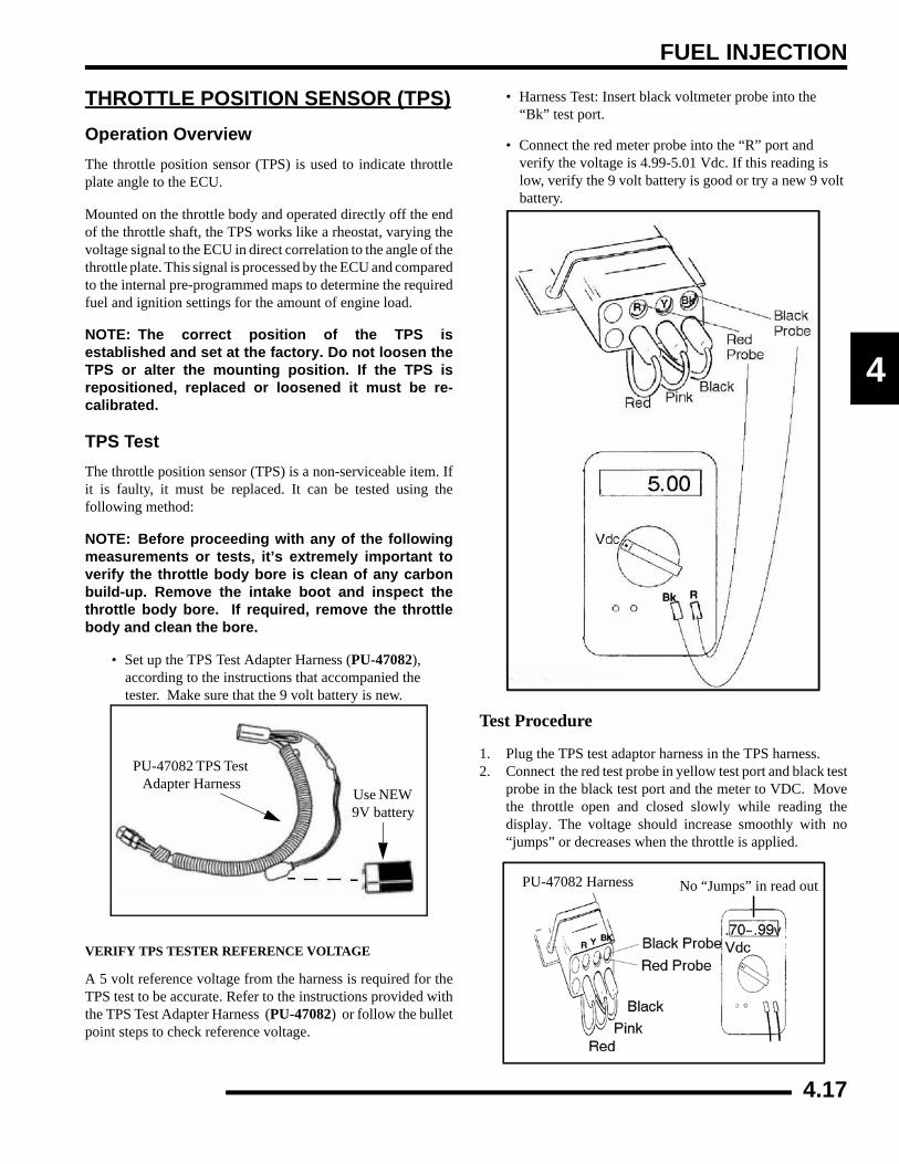
FUEL INJECTION
4
THROTTLE POSITION SENSOR (TPS)Operation OverviewThe throttle position sensor (TPS) is used to indicate throttleplate angle to the ECU.
Mounted on the throttle body and operated directly off the endof the throttle shaft, the TPS works like a rheostat, varying thevoltage signal to the ECU in direct correlation to the angle of thethrottle plate. This signal is processed by the ECU and comparedto the internal pre-programmed maps to determine the requiredfuel and ignition settings for the amount of engine load.
NOTE: The correct position of the TPS isestablished and set at the factory. Do not loosen theTPS or alter the mounting position. If the TPS isrepositioned, replaced or loosened it must be re-calibrated.
TPS TestThe throttle position sensor (TPS) is a non-serviceable item. Ifit is faulty, it must be replaced. It can be tested using thefollowing method:
NOTE: Before proceeding with any of the followingmeasurements or tests, it’s extremely important toverify the throttle body bore is clean of any carbonbuild-up. Remove the intake boot and inspect thethrottle body bore. If required, remove the throttlebody and clean the bore.
• Set up the TPS Test Adapter Harness (PU-47082), according to the instructions that accompanied the tester. Make sure that the 9 volt battery is new.
VERIFY TPS TESTER REFERENCE VOLTAGE
A 5 volt reference voltage from the harness is required for theTPS test to be accurate. Refer to the instructions provided withthe TPS Test Adapter Harness (PU-47082) or follow the bulletpoint steps to check reference voltage.
• Harness Test: Insert black voltmeter probe into the “Bk” test port.
• Connect the red meter probe into the “R” port and verify the voltage is 4.99-5.01 Vdc. If this reading is low, verify the 9 volt battery is good or try a new 9 volt battery.
Test Procedure
1. Plug the TPS test adaptor harness in the TPS harness.2. Connect the red test probe in yellow test port and black test
probe in the black test port and the meter to VDC. Movethe throttle open and closed slowly while reading thedisplay. The voltage should increase smoothly with no“jumps” or decreases when the throttle is applied.
PU-47082 TPS Test Adapter Harness
Use NEW 9V battery
PU-47082 Harness No “Jumps” in read out
4.17
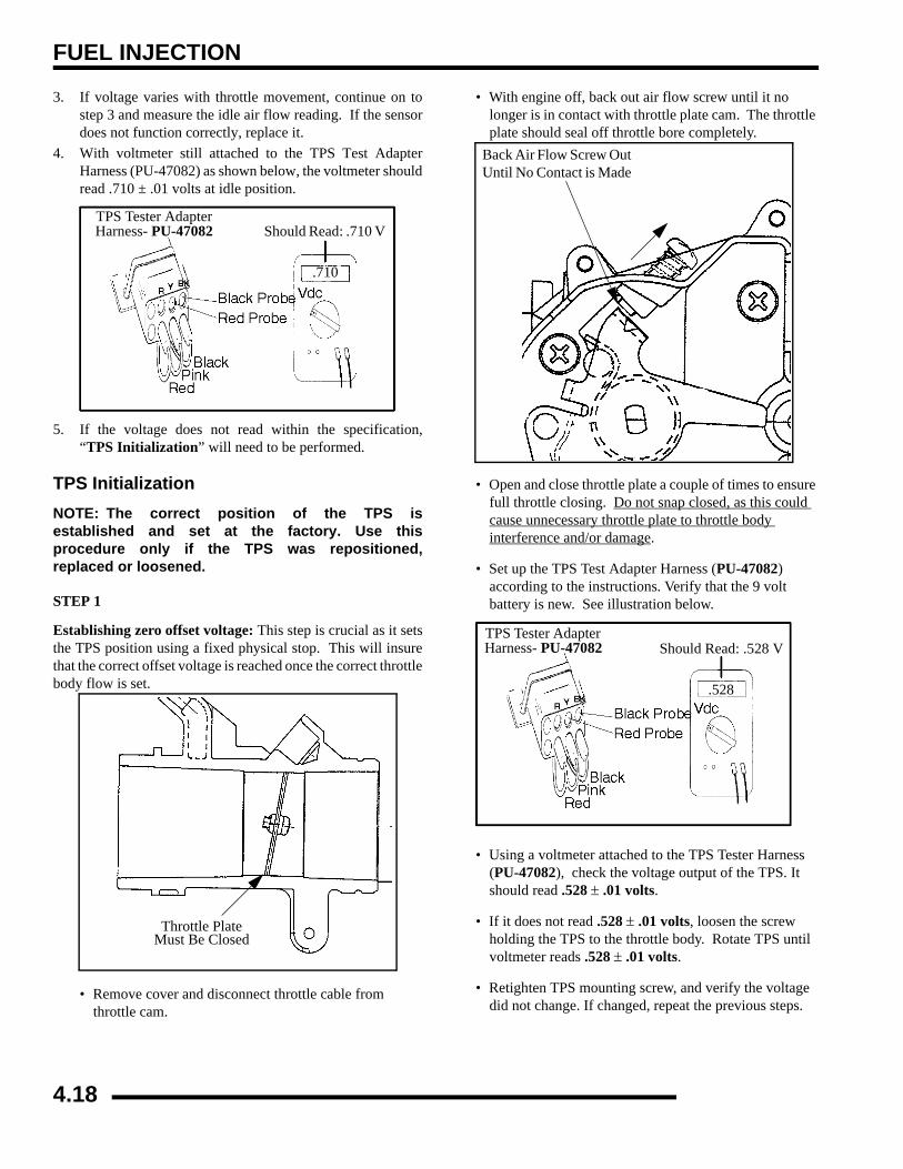
FUEL INJECTION
3. If voltage varies with throttle movement, continue on tostep 3 and measure the idle air flow reading. If the sensordoes not function correctly, replace it.
4. With voltmeter still attached to the TPS Test AdapterHarness (PU-47082) as shown below, the voltmeter shouldread .710 ± .01 volts at idle position.
5. If the voltage does not read within the specification,“TPS Initialization” will need to be performed.
TPS InitializationNOTE: The correct position of the TPS isestablished and set at the factory. Use thisprocedure only if the TPS was repositioned,replaced or loosened.
STEP 1
Establishing zero offset voltage: This step is crucial as it setsthe TPS position using a fixed physical stop. This will insurethat the correct offset voltage is reached once the correct throttlebody flow is set.
• Remove cover and disconnect throttle cable from throttle cam.
• With engine off, back out air flow screw until it no longer is in contact with throttle plate cam. The throttle plate should seal off throttle bore completely.
• Open and close throttle plate a couple of times to ensure full throttle closing. Do not snap closed, as this could cause unnecessary throttle plate to throttle body interference and/or damage.
• Set up the TPS Test Adapter Harness (PU-47082) according to the instructions. Verify that the 9 volt battery is new. See illustration below.
• Using a voltmeter attached to the TPS Tester Harness (PU-47082), check the voltage output of the TPS. It should read .528 ± .01 volts.
• If it does not read .528 ± .01 volts, loosen the screw holding the TPS to the throttle body. Rotate TPS until voltmeter reads .528 ± .01 volts.
• Retighten TPS mounting screw, and verify the voltage did not change. If changed, repeat the previous steps.
TPS Tester Adapter Harness- PU-47082 Should Read: .710 V
.710
Throttle Plate Must Be Closed
Back Air Flow Screw OutUntil No Contact is Made
TPS Tester Adapter Harness- PU-47082
.528
Should Read: .528 V
4.18
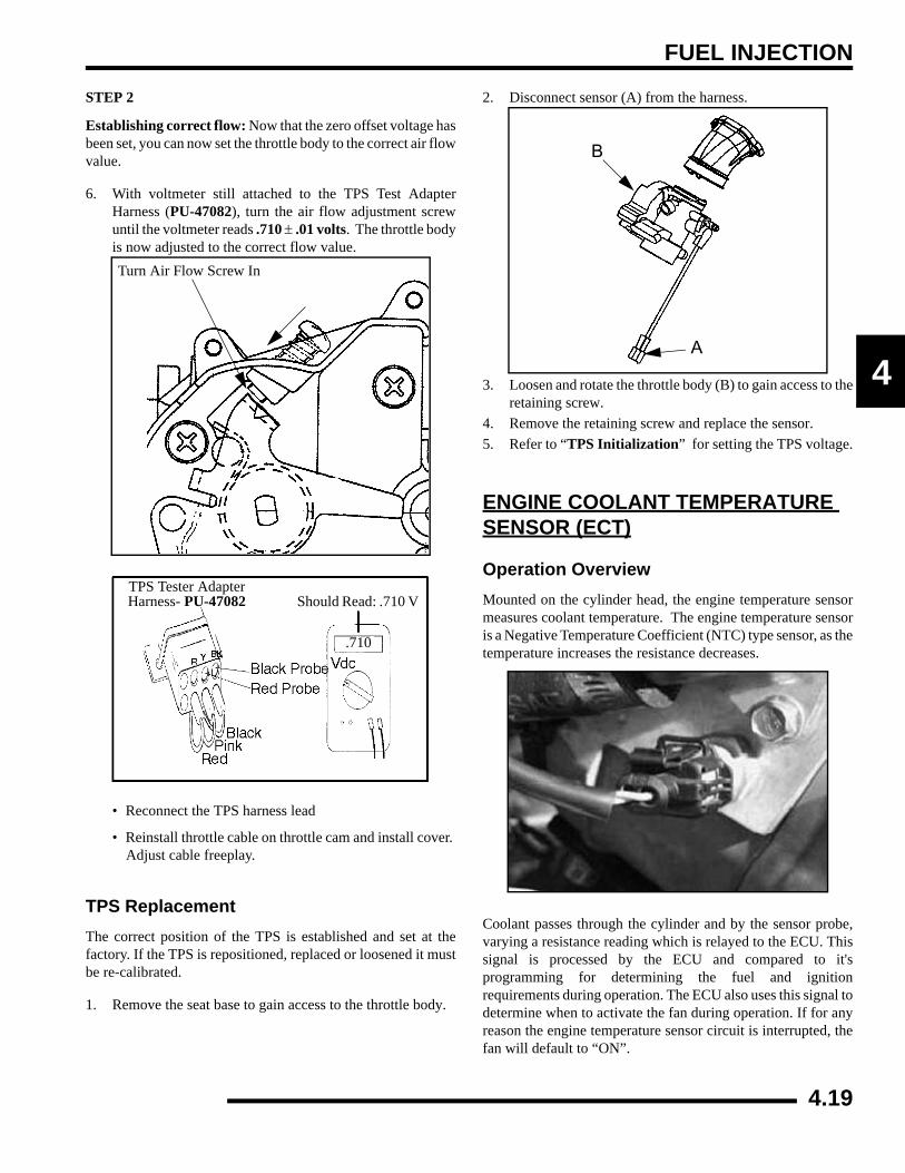
FUEL INJECTION
4
STEP 2
Establishing correct flow: Now that the zero offset voltage hasbeen set, you can now set the throttle body to the correct air flowvalue.
6. With voltmeter still attached to the TPS Test AdapterHarness (PU-47082), turn the air flow adjustment screwuntil the voltmeter reads .710 ± .01 volts. The throttle bodyis now adjusted to the correct flow value.
• Reconnect the TPS harness lead
• Reinstall throttle cable on throttle cam and install cover. Adjust cable freeplay.
TPS ReplacementThe correct position of the TPS is established and set at thefactory. If the TPS is repositioned, replaced or loosened it mustbe re-calibrated.
1. Remove the seat base to gain access to the throttle body.
2. Disconnect sensor (A) from the harness.
3. Loosen and rotate the throttle body (B) to gain access to theretaining screw.
4. Remove the retaining screw and replace the sensor.5. Refer to “TPS Initialization” for setting the TPS voltage.
ENGINE COOLANT TEMPERATURE SENSOR (ECT)
Operation OverviewMounted on the cylinder head, the engine temperature sensormeasures coolant temperature. The engine temperature sensoris a Negative Temperature Coefficient (NTC) type sensor, as thetemperature increases the resistance decreases.
Coolant passes through the cylinder and by the sensor probe,varying a resistance reading which is relayed to the ECU. Thissignal is processed by the ECU and compared to it'sprogramming for determining the fuel and ignitionrequirements during operation. The ECU also uses this signal todetermine when to activate the fan during operation. If for anyreason the engine temperature sensor circuit is interrupted, thefan will default to “ON”.
Turn Air Flow Screw In
TPS Tester Adapter Harness- PU-47082 Should Read: .710 V
.710
A
B
4.19

FUEL INJECTION
ECT Sensor Test
To quickly rule out other components and wiring related to theETS, disconnect the harness from the ETS. The fan should turnon and ‘HOT’ should indicate on the instrument cluster. Thisindicates all other components are working properly.
Refer to Chapter 10 for ECT testing. Polaris dealers can also testthe sensor by using the Digital Wrench™ Diagnostic Software(dealer only). Refer to the Digital Wrench™ User Guide formore information.
ECT Sensor Replacement1. Drain coolant to level below sensor
2. Disconnect sensor from engine harness.
3. Using a wrench, remove and replace the sensor, applyinga light coating of thread sealant to aid installation.
4. Torque the sensor to 17 ft. lbs. (23 Nm).
ECT Sensor Resistance Readings
Temperature °F (°C) Resistance
68 °F (20 °C) 2.5 kΩ ± 6%
212 °F (100 °C) 0.186 kΩ ± 2%
= T
ECT Retaining Bolt Torque:17 ft. lbs. (23 Nm)
Engine Temperature Sensor
4.20
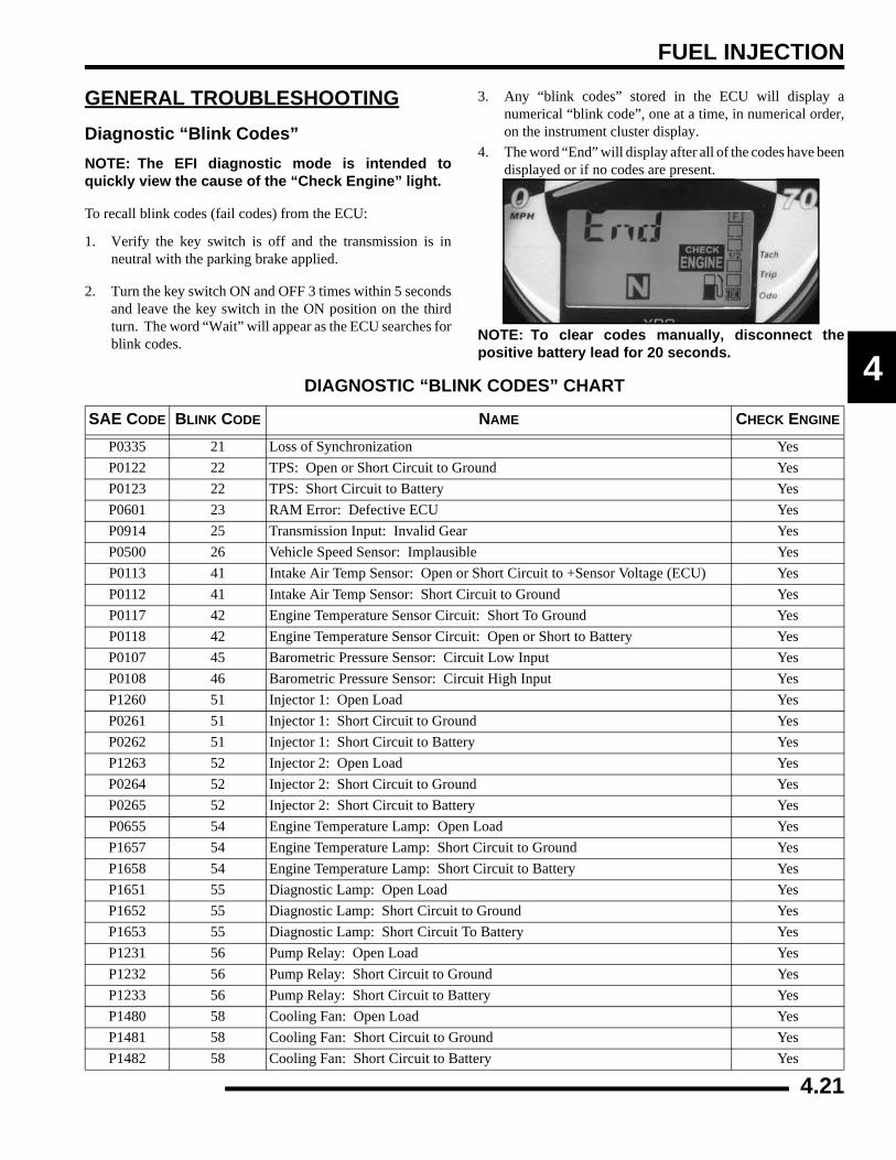
FUEL INJECTION
4
GENERAL TROUBLESHOOTINGDiagnostic “Blink Codes”NOTE: The EFI diagnostic mode is intended toquickly view the cause of the “Check Engine” light.
To recall blink codes (fail codes) from the ECU:
1. Verify the key switch is off and the transmission is inneutral with the parking brake applied.
2. Turn the key switch ON and OFF 3 times within 5 secondsand leave the key switch in the ON position on the thirdturn. The word “Wait” will appear as the ECU searches forblink codes.
3. Any “blink codes” stored in the ECU will display anumerical “blink code”, one at a time, in numerical order,on the instrument cluster display.
4. The word “End” will display after all of the codes have beendisplayed or if no codes are present.
NOTE: To clear codes manually, disconnect thepositive battery lead for 20 seconds.
DIAGNOSTIC “BLINK CODES” CHART
SAE CODE BLINK CODE NAME CHECK ENGINE
P0335 21 Loss of Synchronization YesP0122 22 TPS: Open or Short Circuit to Ground YesP0123 22 TPS: Short Circuit to Battery YesP0601 23 RAM Error: Defective ECU YesP0914 25 Transmission Input: Invalid Gear YesP0500 26 Vehicle Speed Sensor: Implausible YesP0113 41 Intake Air Temp Sensor: Open or Short Circuit to +Sensor Voltage (ECU) YesP0112 41 Intake Air Temp Sensor: Short Circuit to Ground YesP0117 42 Engine Temperature Sensor Circuit: Short To Ground YesP0118 42 Engine Temperature Sensor Circuit: Open or Short to Battery YesP0107 45 Barometric Pressure Sensor: Circuit Low Input YesP0108 46 Barometric Pressure Sensor: Circuit High Input YesP1260 51 Injector 1: Open Load YesP0261 51 Injector 1: Short Circuit to Ground YesP0262 51 Injector 1: Short Circuit to Battery YesP1263 52 Injector 2: Open Load YesP0264 52 Injector 2: Short Circuit to Ground YesP0265 52 Injector 2: Short Circuit to Battery YesP0655 54 Engine Temperature Lamp: Open Load YesP1657 54 Engine Temperature Lamp: Short Circuit to Ground YesP1658 54 Engine Temperature Lamp: Short Circuit to Battery YesP1651 55 Diagnostic Lamp: Open Load YesP1652 55 Diagnostic Lamp: Short Circuit to Ground YesP1653 55 Diagnostic Lamp: Short Circuit To Battery YesP1231 56 Pump Relay: Open Load YesP1232 56 Pump Relay: Short Circuit to Ground YesP1233 56 Pump Relay: Short Circuit to Battery YesP1480 58 Cooling Fan: Open Load YesP1481 58 Cooling Fan: Short Circuit to Ground YesP1482 58 Cooling Fan: Short Circuit to Battery Yes
4.21
FUEL INJECTION
EFI Troubleshooting
Fuel Starvation / Lean Mixture
Symptoms: Hard start or no start, bog, backfire, poppingthrough intake / exhaust, hesitation, detonation, low power,spark plug erosion, engine runs hot, surging, high idle, idlespeed erratic.
• No fuel in tank
• Restricted tank vent, or routed improperly
• Fuel lines or fuel injectors restricted
• Fuel filter plugged
• Fuel pump inoperative
• Air leak in system
• Intake air leak (throttle shaft, intake ducts, airbox or air cleaner cover)
• Incorrect throttle stop screw adjustment
Rich Mixture
Symptoms: Fouls spark plugs, black, sooty exhaust smoke,rough idle, poor fuel economy, engine runs rough/ misses, poorperformance, bog, engine loads up, backfire.
• Air intake restricted (inspect intake duct)
• Air filter dirty/plugged
• Poor fuel quality (old fuel)
• Fouled spark plug
• TPS setting incorrect
• Injector failure
Poor Idle
Symptom: Idle Too High (If greater than 1300 RPM whenengine is warm)
• Throttle stop screw set incorrect
• Throttle cable sticking, improperly adjusted, routed incorrectly
Symptom: Idle Too Low (if less than 900 RPM when engine iswarm)
• Plugged air filter
• Leaking injector (rich condition)
• Belt dragging
• Throttle stop screw tampering
Symptom: Erratic Idle
• Throttle cable incorrectly adjusted
• Air Leaks, dirty injector
• TPS damaged or adjusted
• Tight valves
• Ignition timing incorrect
• Belt dragging
• Dirty air cleaner
• Engine worn
• Spark Plug fouled
• Throttle stop screw set incorrectly (out of sync with ECU)
4.22
BODY / STEERING / SUSPENSION
CHAPTER 5BODY / STEERING / SUSPENSION
5
TORQUE SPECIFICATIONS. . . . . . . . . . . . . . . . . . . . . . . . . . . . . . . . . . . . . . . . . . . . . . . 5.2SPECIAL TOOLS . . . . . . . . . . . . . . . . . . . . . . . . . . . . . . . . . . . . . . . . . . . . . . . . . . . . . . . 5.2BODY COMPONENT REMOVAL . . . . . . . . . . . . . . . . . . . . . . . . . . . . . . . . . . . . . . . . . . . 5.3
REMOVAL PROCEDURES . . . . . . . . . . . . . . . . . . . . . . . . . . . . . . . . . . . . . . . . . . . . . . . 5.3LOWER BODY COMPONENTS. . . . . . . . . . . . . . . . . . . . . . . . . . . . . . . . . . . . . . . . . . . . 5.4HOOD / DASH COMPONENTS . . . . . . . . . . . . . . . . . . . . . . . . . . . . . . . . . . . . . . . . . . . . 5.5DASH INSTRUMENTS AND CONTROLS . . . . . . . . . . . . . . . . . . . . . . . . . . . . . . . . . . . . 5.6
CAB FRAME . . . . . . . . . . . . . . . . . . . . . . . . . . . . . . . . . . . . . . . . . . . . . . . . . . . . . . . . . . . 5.7ASSEMBLY / REMOVAL . . . . . . . . . . . . . . . . . . . . . . . . . . . . . . . . . . . . . . . . . . . . . . . . . 5.7
CHASSIS / MAIN FRAME (4X4) . . . . . . . . . . . . . . . . . . . . . . . . . . . . . . . . . . . . . . . . . . . . 5.8EXPLODED VIEW . . . . . . . . . . . . . . . . . . . . . . . . . . . . . . . . . . . . . . . . . . . . . . . . . . . . . . 5.8
CHASSIS / MAIN FRAME (6X6) . . . . . . . . . . . . . . . . . . . . . . . . . . . . . . . . . . . . . . . . . . . . 5.9EXPLODED VIEW . . . . . . . . . . . . . . . . . . . . . . . . . . . . . . . . . . . . . . . . . . . . . . . . . . . . . . 5.9
SEAT / HEAD REST . . . . . . . . . . . . . . . . . . . . . . . . . . . . . . . . . . . . . . . . . . . . . . . . . . . . 5.10SEAT BASE / SEAT BACK / HEAD REST ASSEMBLY. . . . . . . . . . . . . . . . . . . . . . . . . 5.10
STEERING ASSEMBLY . . . . . . . . . . . . . . . . . . . . . . . . . . . . . . . . . . . . . . . . . . . . . . . . . 5.11EXPLODED VIEW . . . . . . . . . . . . . . . . . . . . . . . . . . . . . . . . . . . . . . . . . . . . . . . . . . . . . 5.11
STEERING AND SUSPENSION . . . . . . . . . . . . . . . . . . . . . . . . . . . . . . . . . . . . . . . . . . . 5.12EXPLODED VIEW . . . . . . . . . . . . . . . . . . . . . . . . . . . . . . . . . . . . . . . . . . . . . . . . . . . . . 5.12
FRONT A-ARM . . . . . . . . . . . . . . . . . . . . . . . . . . . . . . . . . . . . . . . . . . . . . . . . . . . . . . . . 5.13REPLACEMENT. . . . . . . . . . . . . . . . . . . . . . . . . . . . . . . . . . . . . . . . . . . . . . . . . . . . . . . 5.13
FRONT STRUT . . . . . . . . . . . . . . . . . . . . . . . . . . . . . . . . . . . . . . . . . . . . . . . . . . . . . . . . 5.14EXPLODED VIEW . . . . . . . . . . . . . . . . . . . . . . . . . . . . . . . . . . . . . . . . . . . . . . . . . . . . . 5.14FRONT STRUT CARTRIDGE REPLACEMENT . . . . . . . . . . . . . . . . . . . . . . . . . . . . . . 5.15BALL JOINT REPLACEMENT . . . . . . . . . . . . . . . . . . . . . . . . . . . . . . . . . . . . . . . . . . . . 5.15
MID AXLE A-ARM (6X6) . . . . . . . . . . . . . . . . . . . . . . . . . . . . . . . . . . . . . . . . . . . . . . . . . 5.16REPLACEMENT. . . . . . . . . . . . . . . . . . . . . . . . . . . . . . . . . . . . . . . . . . . . . . . . . . . . . . . 5.16
REAR A-ARM (4X4). . . . . . . . . . . . . . . . . . . . . . . . . . . . . . . . . . . . . . . . . . . . . . . . . . . . . 5.17REPLACEMENT. . . . . . . . . . . . . . . . . . . . . . . . . . . . . . . . . . . . . . . . . . . . . . . . . . . . . . . 5.17
REAR STABILIZER BAR (4X4) . . . . . . . . . . . . . . . . . . . . . . . . . . . . . . . . . . . . . . . . . . . . 5.19REMOVAL / INSTALLATION . . . . . . . . . . . . . . . . . . . . . . . . . . . . . . . . . . . . . . . . . . . . . 5.19
SWING ARM (6X6) . . . . . . . . . . . . . . . . . . . . . . . . . . . . . . . . . . . . . . . . . . . . . . . . . . . . . 5.20REMOVAL . . . . . . . . . . . . . . . . . . . . . . . . . . . . . . . . . . . . . . . . . . . . . . . . . . . . . . . . . . . 5.20INSTALLATION . . . . . . . . . . . . . . . . . . . . . . . . . . . . . . . . . . . . . . . . . . . . . . . . . . . . . . . 5.20
REAR DRIVE AXLE AND SWINGARM EXPLODED VIEW (6X6) . . . . . . . . . . . . . . . . . 5.21REAR CARGO BOX . . . . . . . . . . . . . . . . . . . . . . . . . . . . . . . . . . . . . . . . . . . . . . . . . . . . 5.22
CARGO BOX - PANELS. . . . . . . . . . . . . . . . . . . . . . . . . . . . . . . . . . . . . . . . . . . . . . . . . 5.22CARGO BOX - TAILGATE / BOX SUPPORT. . . . . . . . . . . . . . . . . . . . . . . . . . . . . . . . . 5.23BOX REMOVAL . . . . . . . . . . . . . . . . . . . . . . . . . . . . . . . . . . . . . . . . . . . . . . . . . . . . . . . 5.24BOX INSTALLATION . . . . . . . . . . . . . . . . . . . . . . . . . . . . . . . . . . . . . . . . . . . . . . . . . . . 5.24
STORAGE BOX. . . . . . . . . . . . . . . . . . . . . . . . . . . . . . . . . . . . . . . . . . . . . . . . . . . . . . . . 5.25REMOVAL . . . . . . . . . . . . . . . . . . . . . . . . . . . . . . . . . . . . . . . . . . . . . . . . . . . . . . . . . . . 5.25INSTALLATION . . . . . . . . . . . . . . . . . . . . . . . . . . . . . . . . . . . . . . . . . . . . . . . . . . . . . . . 5.25
DECAL REPLACEMENT. . . . . . . . . . . . . . . . . . . . . . . . . . . . . . . . . . . . . . . . . . . . . . . . . 5.25
5.1
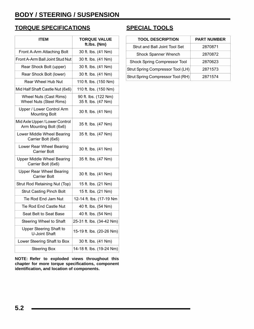
BODY / STEERING / SUSPENSION
TORQUE SPECIFICATIONS
NOTE: Refer to exploded views throughout thischapter for more torque specifications, componentidentification, and location of components.
SPECIAL TOOLS
ITEM TORQUE VALUEft.lbs. (Nm)
Front A-Arm Attaching Bolt 30 ft. lbs. (41 Nm)
Front A-Arm Ball Joint Stud Nut 30 ft. lbs. (41 Nm)
Rear Shock Bolt (upper) 30 ft. lbs. (41 Nm)
Rear Shock Bolt (lower) 30 ft. lbs. (41 Nm)
Rear Wheel Hub Nut 110 ft. lbs. (150 Nm)
Mid Half Shaft Castle Nut (6x6) 110 ft. lbs. (150 Nm)
Wheel Nuts (Cast Rims)Wheel Nuts (Steel Rims)
90 ft. lbs. (122 Nm)35 ft. lbs. (47 Nm)
Upper / Lower Control Arm Mounting Bolt
30 ft. lbs. (41 Nm)
Mid Axle Upper / Lower Control Arm Mounting Bolt (6x6)
35 ft. lbs. (47 Nm)
Lower Middle Wheel Bearing Carrier Bolt (6x6)
35 ft. lbs. (47 Nm)
Lower Rear Wheel Bearing Carrier Bolt
30 ft. lbs. (41 Nm)
Upper Middle Wheel Bearing Carrier Bolt (6x6)
35 ft. lbs. (47 Nm)
Upper Rear Wheel Bearing Carrier Bolt
30 ft. lbs. (41 Nm)
Strut Rod Retaining Nut (Top) 15 ft. lbs. (21 Nm)
Strut Casting Pinch Bolt 15 ft. lbs. (21 Nm)
Tie Rod End Jam Nut 12-14 ft. lbs. (17-19 Nm
Tie Rod End Castle Nut 40 ft. lbs. (54 Nm)
Seat Belt to Seat Base 40 ft. lbs. (54 Nm)
Steering Wheel to Shaft 25-31 ft. lbs. (34-42 Nm)
Upper Steering Shaft to U-Joint Shaft
15-19 ft. lbs. (20-26 Nm)
Lower Steering Shaft to Box 30 ft. lbs. (41 Nm)
Steering Box 14-18 ft. lbs. (19-24 Nm)
TOOL DESCRIPTION PART NUMBER
Strut and Ball Joint Tool Set 2870871
Shock Spanner Wrench 2870872
Shock Spring Compressor Tool 2870623
Strut Spring Compressor Tool (LH) 2871573
Strut Spring Compressor Tool (RH) 2871574
5.2
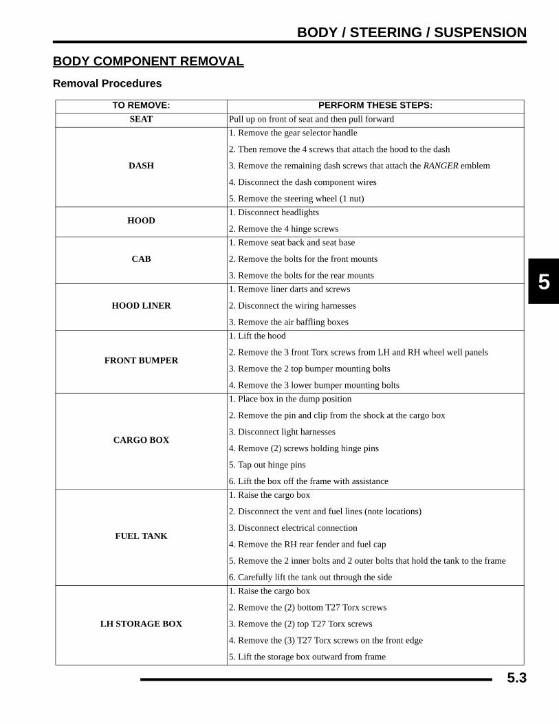
BODY / STEERING / SUSPENSION
5
BODY COMPONENT REMOVALRemoval Procedures
TO REMOVE: PERFORM THESE STEPS:SEAT Pull up on front of seat and then pull forward
DASH
1. Remove the gear selector handle
2. Then remove the 4 screws that attach the hood to the dash
3. Remove the remaining dash screws that attach the RANGER emblem
4. Disconnect the dash component wires
5. Remove the steering wheel (1 nut)
HOOD1. Disconnect headlights
2. Remove the 4 hinge screws
CAB
1. Remove seat back and seat base
2. Remove the bolts for the front mounts
3. Remove the bolts for the rear mounts
HOOD LINER
1. Remove liner darts and screws
2. Disconnect the wiring harnesses
3. Remove the air baffling boxes
FRONT BUMPER
1. Lift the hood
2. Remove the 3 front Torx screws from LH and RH wheel well panels
3. Remove the 2 top bumper mounting bolts
4. Remove the 3 lower bumper mounting bolts
CARGO BOX
1. Place box in the dump position
2. Remove the pin and clip from the shock at the cargo box
3. Disconnect light harnesses
4. Remove (2) screws holding hinge pins
5. Tap out hinge pins
6. Lift the box off the frame with assistance
FUEL TANK
1. Raise the cargo box
2. Disconnect the vent and fuel lines (note locations)
3. Disconnect electrical connection
4. Remove the RH rear fender and fuel cap
5. Remove the 2 inner bolts and 2 outer bolts that hold the tank to the frame
6. Carefully lift the tank out through the side
LH STORAGE BOX
1. Raise the cargo box
2. Remove the (2) bottom T27 Torx screws
3. Remove the (2) top T27 Torx screws
4. Remove the (3) T27 Torx screws on the front edge
5. Lift the storage box outward from frame
5.3
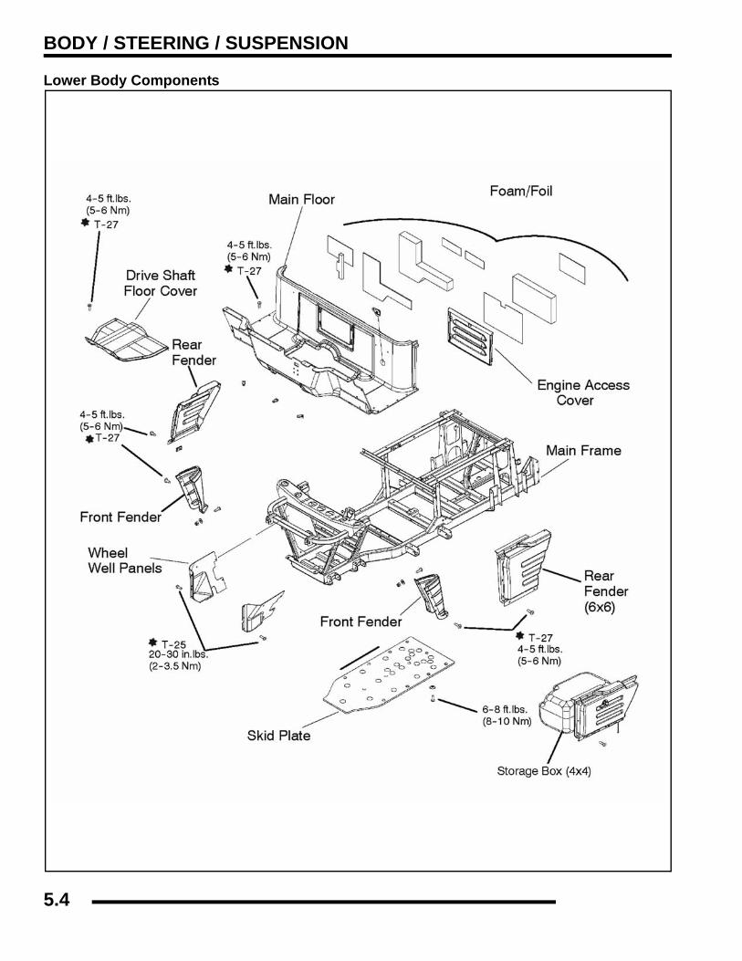
BODY / STEERING / SUSPENSION
Lower Body Components
5.4
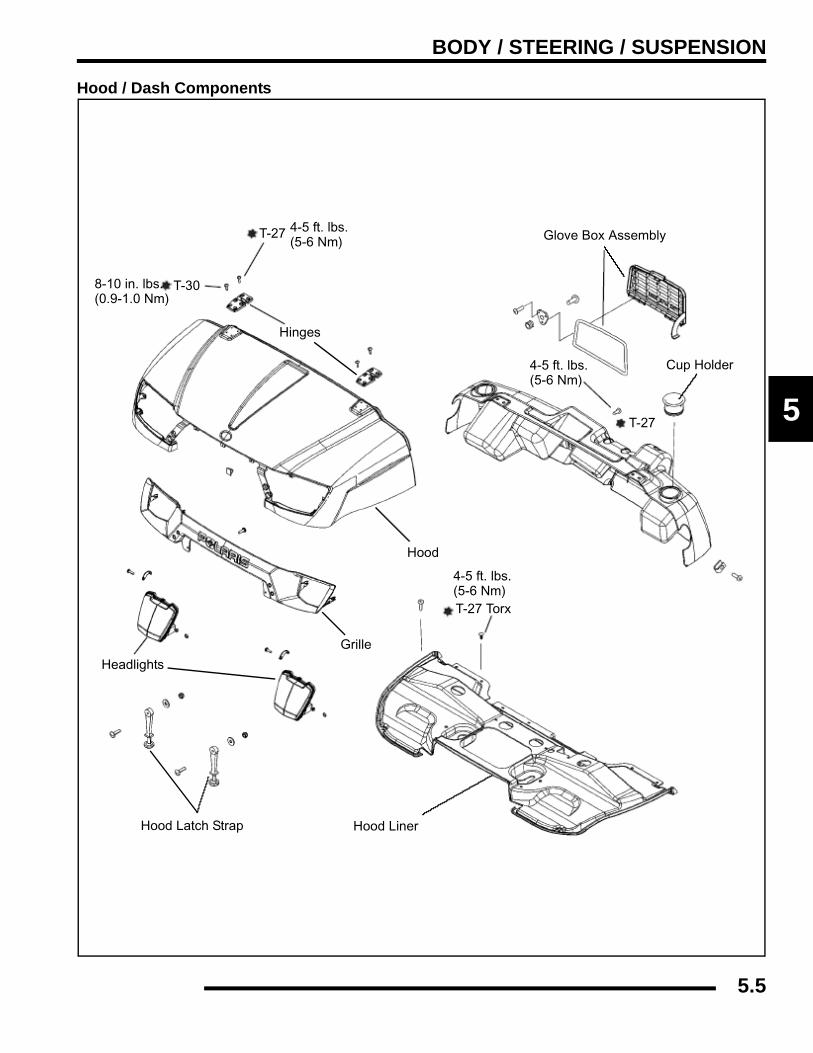
BODY / STEERING / SUSPENSION
5
Hood / Dash Components
Glove Box Assembly
Cup Holder
Hood
Hood LinerHood Latch Strap
Headlights
Hinges
T-27 4-5 ft. lbs.(5-6 Nm)
8-10 in. lbs.(0.9-1.0 Nm)
T-30
T-27 Torx
4-5 ft. lbs.(5-6 Nm)
T-27
4-5 ft. lbs.(5-6 Nm)
Grille
5.5

BODY / STEERING / SUSPENSION
Dash Instruments and Controls
C
DEF
G
A. Speedometer
B. Headlight Switch
C. 2WD/AWD Switch
D. 12 Volt Accessory Receptacle
E. Speedometer “Mode” Button
F. Key Switch
G. Speedometer Mount Plate
B
C
D
B
EF
GA
A
5.6
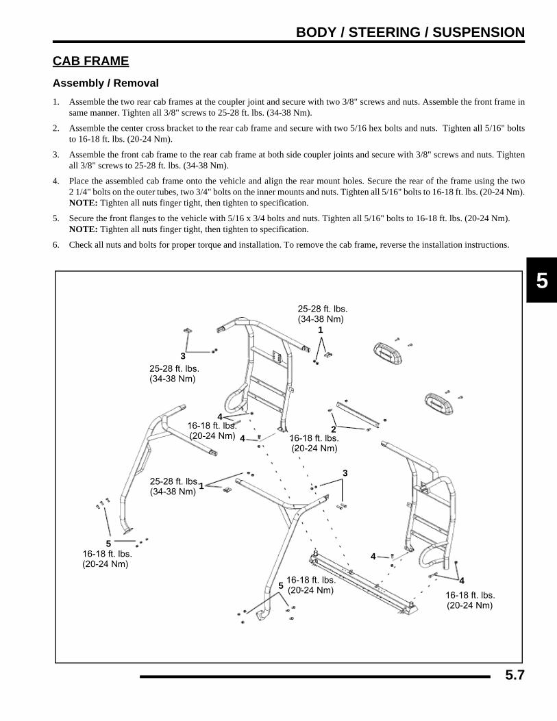
BODY / STEERING / SUSPENSION
5
CAB FRAMEAssembly / Removal1. Assemble the two rear cab frames at the coupler joint and secure with two 3/8" screws and nuts. Assemble the front frame in
same manner. Tighten all 3/8" screws to 25-28 ft. lbs. (34-38 Nm).
2. Assemble the center cross bracket to the rear cab frame and secure with two 5/16 hex bolts and nuts. Tighten all 5/16" boltsto 16-18 ft. lbs. (20-24 Nm).
3. Assemble the front cab frame to the rear cab frame at both side coupler joints and secure with 3/8" screws and nuts. Tightenall 3/8" screws to 25-28 ft. lbs. (34-38 Nm).
4. Place the assembled cab frame onto the vehicle and align the rear mount holes. Secure the rear of the frame using the two2 1/4" bolts on the outer tubes, two 3/4" bolts on the inner mounts and nuts. Tighten all 5/16" bolts to 16-18 ft. lbs. (20-24 Nm).NOTE: Tighten all nuts finger tight, then tighten to specification.
5. Secure the front flanges to the vehicle with 5/16 x 3/4 bolts and nuts. Tighten all 5/16" bolts to 16-18 ft. lbs. (20-24 Nm). NOTE: Tighten all nuts finger tight, then tighten to specification.
6. Check all nuts and bolts for proper torque and installation. To remove the cab frame, reverse the installation instructions.
1
2
3
4
5 4
5
1
3
16-18 ft. lbs.(20-24 Nm)
16-18 ft. lbs.(20-24 Nm) 16-18 ft. lbs.
(20-24 Nm)
16-18 ft. lbs.(20-24 Nm)
16-18 ft. lbs.(20-24 Nm)
4
25-28 ft. lbs.(34-38 Nm)
25-28 ft. lbs.(34-38 Nm)
25-28 ft. lbs.(34-38 Nm)
4
5.7
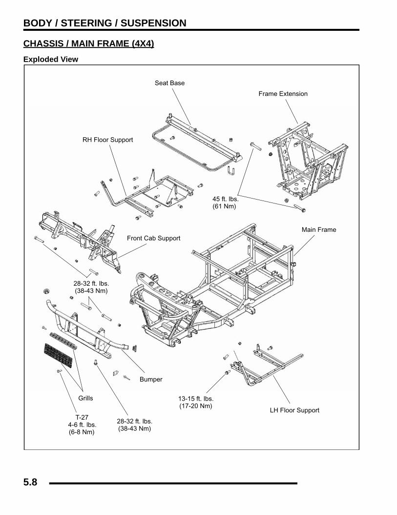
BODY / STEERING / SUSPENSION
CHASSIS / MAIN FRAME (4X4)Exploded View
Seat Base
Front Cab Support
Bumper
Grills
LH Floor Support
45 ft. lbs.(61 Nm)
RH Floor Support
28-32 ft. lbs.(38-43 Nm)
28-32 ft. lbs.(38-43 Nm)
13-15 ft. lbs.(17-20 Nm)
Frame Extension
Main Frame
T-274-6 ft. lbs.(6-8 Nm)
5.8
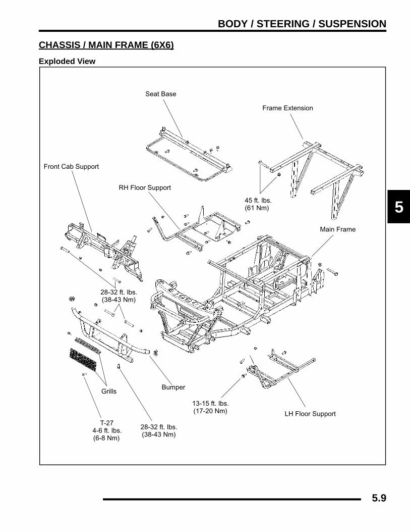
BODY / STEERING / SUSPENSION
5
CHASSIS / MAIN FRAME (6X6)Exploded View
Seat Base
Front Cab Support
BumperGrills
LH Floor Support
45 ft. lbs.(61 Nm)
RH Floor Support
28-32 ft. lbs.(38-43 Nm)
28-32 ft. lbs.(38-43 Nm)
13-15 ft. lbs.(17-20 Nm)
Frame Extension
Main Frame
T-274-6 ft. lbs.(6-8 Nm)
5.9
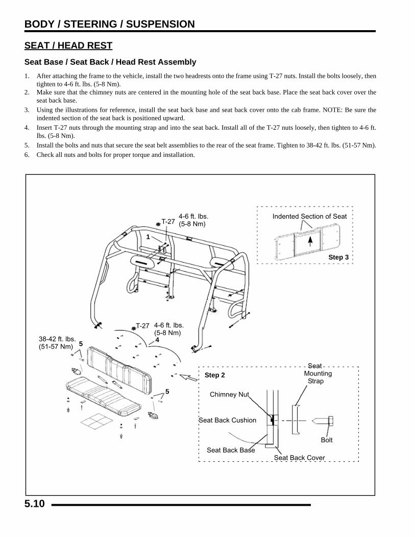
BODY / STEERING / SUSPENSION
SEAT / HEAD RESTSeat Base / Seat Back / Head Rest Assembly1. After attaching the frame to the vehicle, install the two headrests onto the frame using T-27 nuts. Install the bolts loosely, then
tighten to 4-6 ft. lbs. (5-8 Nm).2. Make sure that the chimney nuts are centered in the mounting hole of the seat back base. Place the seat back cover over the
seat back base.3. Using the illustrations for reference, install the seat back base and seat back cover onto the cab frame. NOTE: Be sure the
indented section of the seat back is positioned upward.4. Insert T-27 nuts through the mounting strap and into the seat back. Install all of the T-27 nuts loosely, then tighten to 4-6 ft.
lbs. (5-8 Nm).5. Install the bolts and nuts that secure the seat belt assemblies to the rear of the seat frame. Tighten to 38-42 ft. lbs. (51-57 Nm).6. Check all nuts and bolts for proper torque and installation.
T-27
Step 3
Indented Section of Seat4-6 ft. lbs.(5-8 Nm)
38-42 ft. lbs.(51-57 Nm)
Chimney Nut
SeatMounting Strap
Seat Back Cushion
Bolt
Seat Back BaseSeat Back Cover
T-27 4-6 ft. lbs.(5-8 Nm)
1
45
5
Step 2
5.10
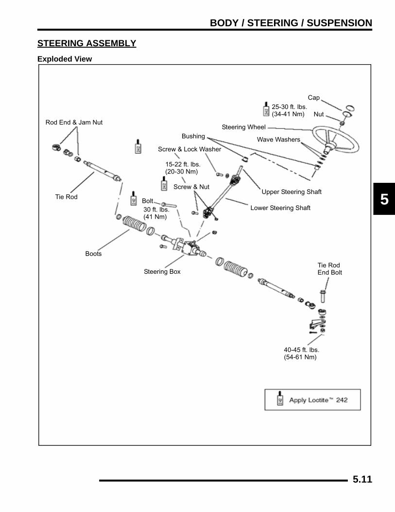
BODY / STEERING / SUSPENSION
5
STEERING ASSEMBLYExploded View
Rod End & Jam Nut
Tie Rod
Boots
Steering BoxTie Rod End Bolt
Lower Steering Shaft
Upper Steering Shaft
Cap
Nut
Steering Wheel
Wave WashersBushing
Screw & Lock Washer
25-30 ft. lbs.(34-41 Nm)
30 ft. lbs.(41 Nm)
15-22 ft. lbs.(20-30 Nm)
Bolt
40-45 ft. lbs.(54-61 Nm)
Screw & Nut
5.11

BODY / STEERING / SUSPENSION
STEERING AND SUSPENSIONExploded View
Always use new boltsupon reassembly
Always use new cotter pins upon reassembly.
NOTE: To avoid damage to the tie rod ends andother steering components, be sure to install tie rod end bolts in the proper direction. The stee-ring post arm bolt (B) points up; the rod end bolts (A) point down. Be sure inner rod ends are placed between the steering post arms.
Apply LoctiteTM 242
15-22 ft. lbs.(20-30 Nm)
30 ft. lbs.(41 Nm)
Front
12-14 ft. lbs.(16-19 Nm)
30 ft. lbs.(41 Nm)
30 ft. lbs.(41 Nm)
25-30 ft. lbs.(34-41 Nm)
40-45 ft. lbs.(54-61 Nm)
25 ft. lbs.(35 Nm)
8 ft. lbs.(11 Nm)
20-30 ft. lbs.(2-3.5 Nm)
5.12
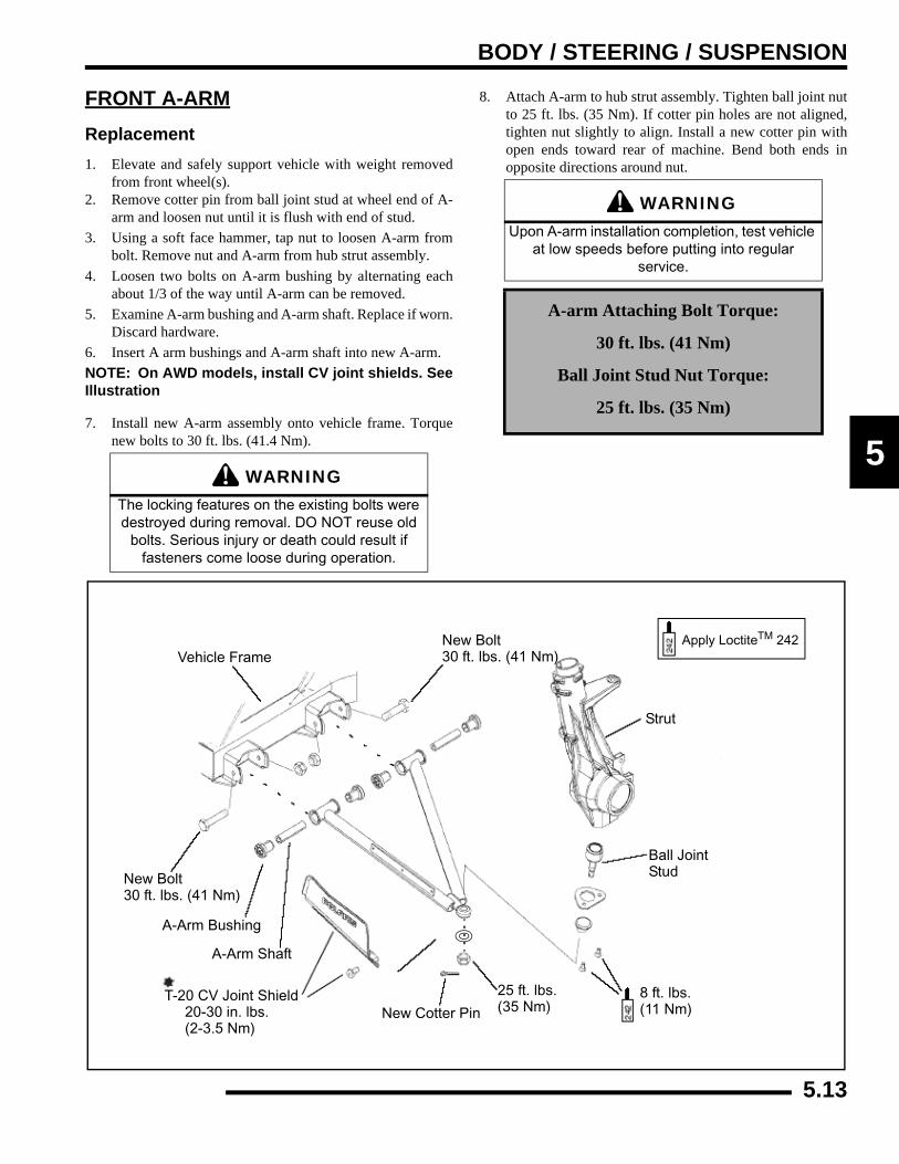
BODY / STEERING / SUSPENSION
5
FRONT A-ARMReplacement1. Elevate and safely support vehicle with weight removed
from front wheel(s).2. Remove cotter pin from ball joint stud at wheel end of A-
arm and loosen nut until it is flush with end of stud.3. Using a soft face hammer, tap nut to loosen A-arm from
bolt. Remove nut and A-arm from hub strut assembly.4. Loosen two bolts on A-arm bushing by alternating each
about 1/3 of the way until A-arm can be removed.5. Examine A-arm bushing and A-arm shaft. Replace if worn.
Discard hardware.6. Insert A arm bushings and A-arm shaft into new A-arm.NOTE: On AWD models, install CV joint shields. SeeIllustration
7. Install new A-arm assembly onto vehicle frame. Torquenew bolts to 30 ft. lbs. (41.4 Nm).
8. Attach A-arm to hub strut assembly. Tighten ball joint nutto 25 ft. lbs. (35 Nm). If cotter pin holes are not aligned,tighten nut slightly to align. Install a new cotter pin withopen ends toward rear of machine. Bend both ends inopposite directions around nut.
WARNINGThe locking features on the existing bolts were destroyed during removal. DO NOT reuse old
bolts. Serious injury or death could result if fasteners come loose during operation.
WARNINGUpon A-arm installation completion, test vehicle
at low speeds before putting into regular service.
A-arm Attaching Bolt Torque:
30 ft. lbs. (41 Nm)
Ball Joint Stud Nut Torque:
25 ft. lbs. (35 Nm)
Apply LoctiteTM 242Vehicle Frame
New Bolt30 ft. lbs. (41 Nm)
Strut
Ball Joint Stud
8 ft. lbs.(11 Nm)
25 ft. lbs.(35 Nm)New Cotter Pin
A-Arm Bushing
A-Arm Shaft
T-20 CV Joint Shield 20-30 in. lbs. (2-3.5 Nm)
New Bolt30 ft. lbs. (41 Nm)
5.13

BODY / STEERING / SUSPENSION
FRONT STRUTExploded View
Nut15 ft. lbs.(21 Nm)
Washer
Spacer Rubber
Top
Spacer
Bottom
Spring
Spring
Washer
Bolt
Bearing
Retaining Ring
Washer
Clamp
Front Strut
Strut Bumper
18 ft. lbs.(24 Nm)
Pivot Ball
RetainerPivot Ball
18 ft. lbs.(24 Nm)
Wheel Speed Sensor(Hall Effect Sensor)
5.14
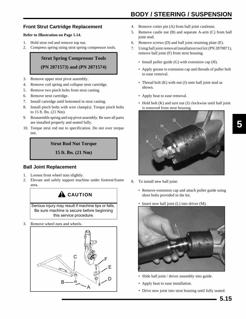
BODY / STEERING / SUSPENSION
5
Front Strut Cartridge ReplacementRefer to Illustration on Page 5.14.
1. Hold strut rod and remove top nut.2. Compress spring using strut spring compressor tools.
3. Remove upper strut pivot assembly.4. Remove coil spring and collapse strut cartridge.5. Remove two pinch bolts from strut casting.6. Remove strut cartridge.7. Install cartridge until bottomed in strut casting.8. Install pinch bolts with wire clamp(s). Torque pinch bolts
to 15 ft. lbs. (21 Nm).9. Reassemble spring and top pivot assembly. Be sure all parts
are installed properly and seated fully.10. Torque strut rod nut to specification. Do not over torque
nut.
Ball Joint Replacement1. Loosen front wheel nuts slightly.2. Elevate and safely support machine under footrest/frame
area.
3. Remove wheel nuts and wheels.
4. Remove cotter pin (A) from ball joint castlenut.5. Remove castle nut (B) and separate A-arm (C) from ball
joint stud.6. Remove screws (D) and ball joint retaining plate (E).7. Using ball joint removal/installation tool kit (PN 2870871),
remove ball joint (F) from strut housing.
• Install puller guide (G) with extension cap (H).
• Apply grease to extension cap and threads of puller bolt to ease removal.
• Thread bolt (K) with nut (J) onto ball joint stud as shown.
• Apply heat to ease removal.
• Hold bolt (K) and turn nut (J) clockwise until ball joint is removed from strut housing.
8. To install new ball joint:
• Remove extension cap and attach puller guide using short bolts provided in the kit.
• Insert new ball joint (L) into driver (M).
• Slide ball joint / driver assembly into guide.
• Apply heat to ease installation.
• Drive new joint into strut housing until fully seated.
Strut Spring Compressor Tools
(PN 2871573) and (PN 2871574)
Strut Rod Nut Torque
15 ft. lbs. (21 Nm)
CAUTION
Serious injury may result if machine tips or falls. Be sure machine is secure before beginning
this service procedure.
AB
C
D
E
F
GH
JK
L
M
5.15
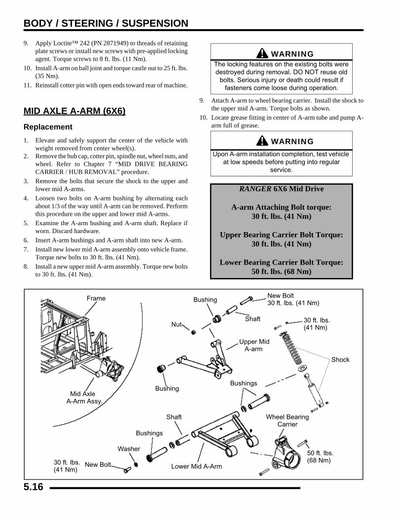
BODY / STEERING / SUSPENSION
9. Apply Loctite™ 242 (PN 2871949) to threads of retainingplate screws or install new screws with pre-applied lockingagent. Torque screws to 8 ft. lbs. (11 Nm).
10. Install A-arm on ball joint and torque castle nut to 25 ft. lbs.(35 Nm).
11. Reinstall cotter pin with open ends toward rear of machine.
MID AXLE A-ARM (6X6)Replacement1. Elevate and safely support the center of the vehicle with
weight removed from center wheel(s).2. Remove the hub cap, cotter pin, spindle nut, wheel nuts, and
wheel. Refer to Chapter 7 “MID DRIVE BEARINGCARRIER / HUB REMOVAL” procedure.
3. Remove the bolts that secure the shock to the upper andlower mid A-arms.
4. Loosen two bolts on A-arm bushing by alternating eachabout 1/3 of the way until A-arm can be removed. Performthis procedure on the upper and lower mid A-arms.
5. Examine the A-arm bushing and A-arm shaft. Replace ifworn. Discard hardware.
6. Insert A-arm bushings and A-arm shaft into new A-arm.7. Install new lower mid A-arm assembly onto vehicle frame.
Torque new bolts to 30 ft. lbs. (41 Nm).8. Install a new upper mid A-arm assembly. Torque new bolts
to 30 ft. lbs. (41 Nm).
9. Attach A-arm to wheel bearing carrier. Install the shock tothe upper mid A-arm. Torque bolts as shown.
10. Locate grease fitting in center of A-arm tube and pump A-arm full of grease.
Frame New Bolt30 ft. lbs. (41 Nm)
Mid AxleA-Arm Assy.
Bushings
Washer
New Bolt
30 ft. lbs.(41 Nm)
Lower Mid A-Arm
50 ft. lbs.(68 Nm)
Wheel BearingCarrier
BushingsBushing
Bushing
NutShaft
Shock
30 ft. lbs.(41 Nm)
Upper Mid A-arm
Shaft
WARNINGThe locking features on the existing bolts were destroyed during removal. DO NOT reuse old
bolts. Serious injury or death could result if fasteners come loose during operation.
WARNINGUpon A-arm installation completion, test vehicle
at low speeds before putting into regular service.
RANGER 6X6 Mid Drive
A-arm Attaching Bolt torque:30 ft. lbs. (41 Nm)
Upper Bearing Carrier Bolt Torque:30 ft. lbs. (41 Nm)
Lower Bearing Carrier Bolt Torque:50 ft. lbs. (68 Nm)
5.16
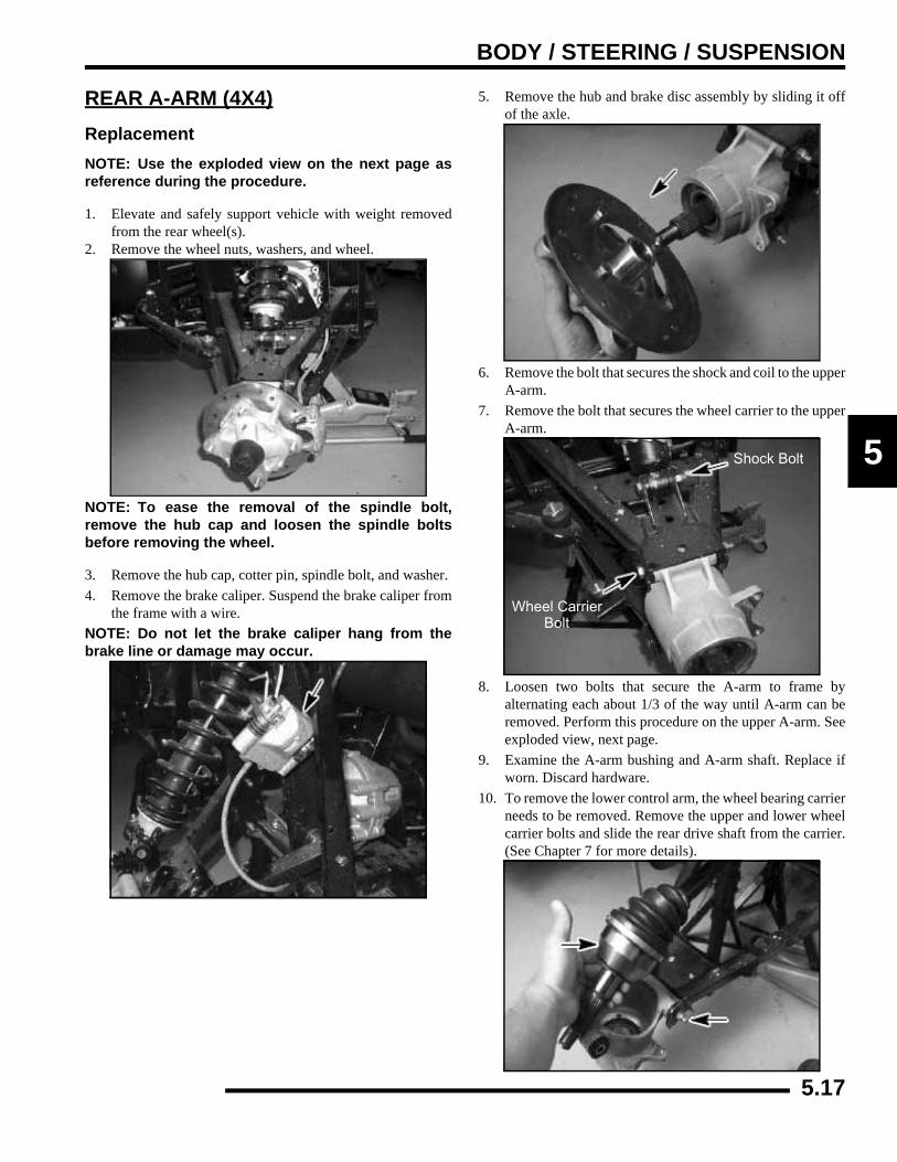
BODY / STEERING / SUSPENSION
5
REAR A-ARM (4X4)ReplacementNOTE: Use the exploded view on the next page asreference during the procedure.
1. Elevate and safely support vehicle with weight removedfrom the rear wheel(s).
2. Remove the wheel nuts, washers, and wheel.
NOTE: To ease the removal of the spindle bolt,remove the hub cap and loosen the spindle boltsbefore removing the wheel.
3. Remove the hub cap, cotter pin, spindle bolt, and washer.4. Remove the brake caliper. Suspend the brake caliper from
the frame with a wire. NOTE: Do not let the brake caliper hang from thebrake line or damage may occur.
5. Remove the hub and brake disc assembly by sliding it offof the axle.
6. Remove the bolt that secures the shock and coil to the upperA-arm.
7. Remove the bolt that secures the wheel carrier to the upperA-arm.
8. Loosen two bolts that secure the A-arm to frame byalternating each about 1/3 of the way until A-arm can beremoved. Perform this procedure on the upper A-arm. Seeexploded view, next page.
9. Examine the A-arm bushing and A-arm shaft. Replace ifworn. Discard hardware.
10. To remove the lower control arm, the wheel bearing carrierneeds to be removed. Remove the upper and lower wheelcarrier bolts and slide the rear drive shaft from the carrier.(See Chapter 7 for more details).
Shock Bolt
Wheel CarrierBolt
5.17
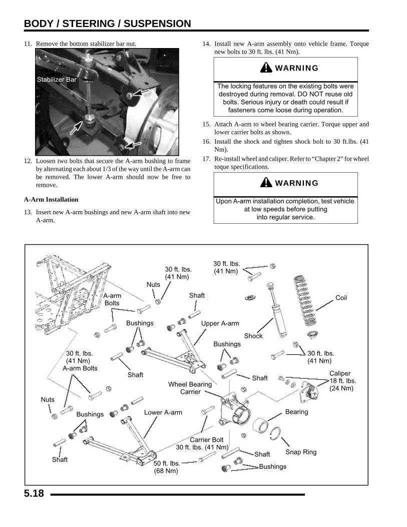
BODY / STEERING / SUSPENSION
11. Remove the bottom stabilizer bar nut.
12. Loosen two bolts that secure the A-arm bushing to frameby alternating each about 1/3 of the way until the A-arm canbe removed. The lower A-arm should now be free toremove.
A-Arm Installation
13. Insert new A-arm bushings and new A-arm shaft into newA-arm.
14. Install new A-arm assembly onto vehicle frame. Torquenew bolts to 30 ft. lbs. (41 Nm).
15. Attach A-arm to wheel bearing carrier. Torque upper andlower carrier bolts as shown.
16. Install the shock and tighten shock bolt to 30 ft.lbs. (41Nm).
17. Re-install wheel and caliper. Refer to “Chapter 2” for wheeltoque specifications.
Stabilizer Bar
WARNING
The locking features on the existing bolts were destroyed during removal. DO NOT reuse old
bolts. Serious injury or death could result if fasteners come loose during operation.
WARNING
Upon A-arm installation completion, test vehicle at low speeds before putting
into regular service.
A-arm Shaft
Upper A-arm
Bushings
Coil
Snap Ring
Bushings
Lower A-arm
Carrier Bolt30 ft. lbs. (41 Nm)
Shaft
Nuts
Nuts
30 ft. lbs.(41 Nm)
30 ft. lbs.(41 Nm)
Shock
30 ft. lbs.(41 Nm)
Caliper18 ft. lbs.(24 Nm)
Bearing
Bushings
ShaftShaft
30 ft. lbs.(41 Nm)
A-arm Bolts
Wheel BearingCarrier
Bushings
Bolts
50 ft. lbs.(68 Nm)
Shaft
5.18
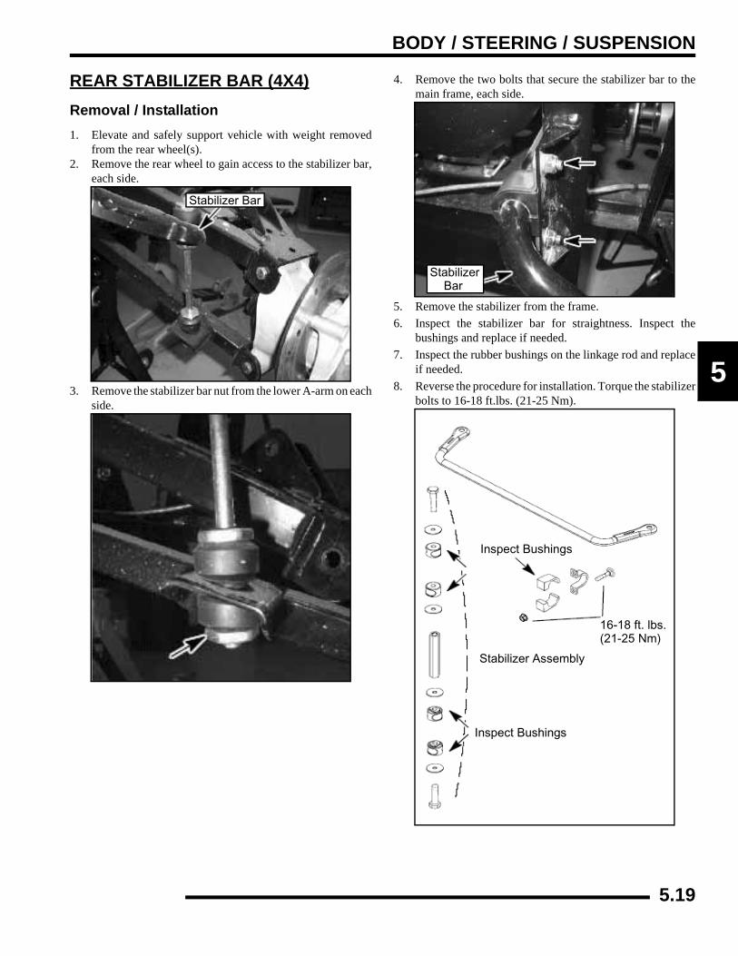
BODY / STEERING / SUSPENSION
5
REAR STABILIZER BAR (4X4)Removal / Installation1. Elevate and safely support vehicle with weight removed
from the rear wheel(s).2. Remove the rear wheel to gain access to the stabilizer bar,
each side.
3. Remove the stabilizer bar nut from the lower A-arm on eachside.
4. Remove the two bolts that secure the stabilizer bar to themain frame, each side.
5. Remove the stabilizer from the frame.6. Inspect the stabilizer bar for straightness. Inspect the
bushings and replace if needed.7. Inspect the rubber bushings on the linkage rod and replace
if needed.8. Reverse the procedure for installation. Torque the stabilizer
bolts to 16-18 ft.lbs. (21-25 Nm).
Stabilizer Bar
StabilizerBar
Inspect Bushings
Stabilizer Assembly
16-18 ft. lbs.(21-25 Nm)
Inspect Bushings
5.19
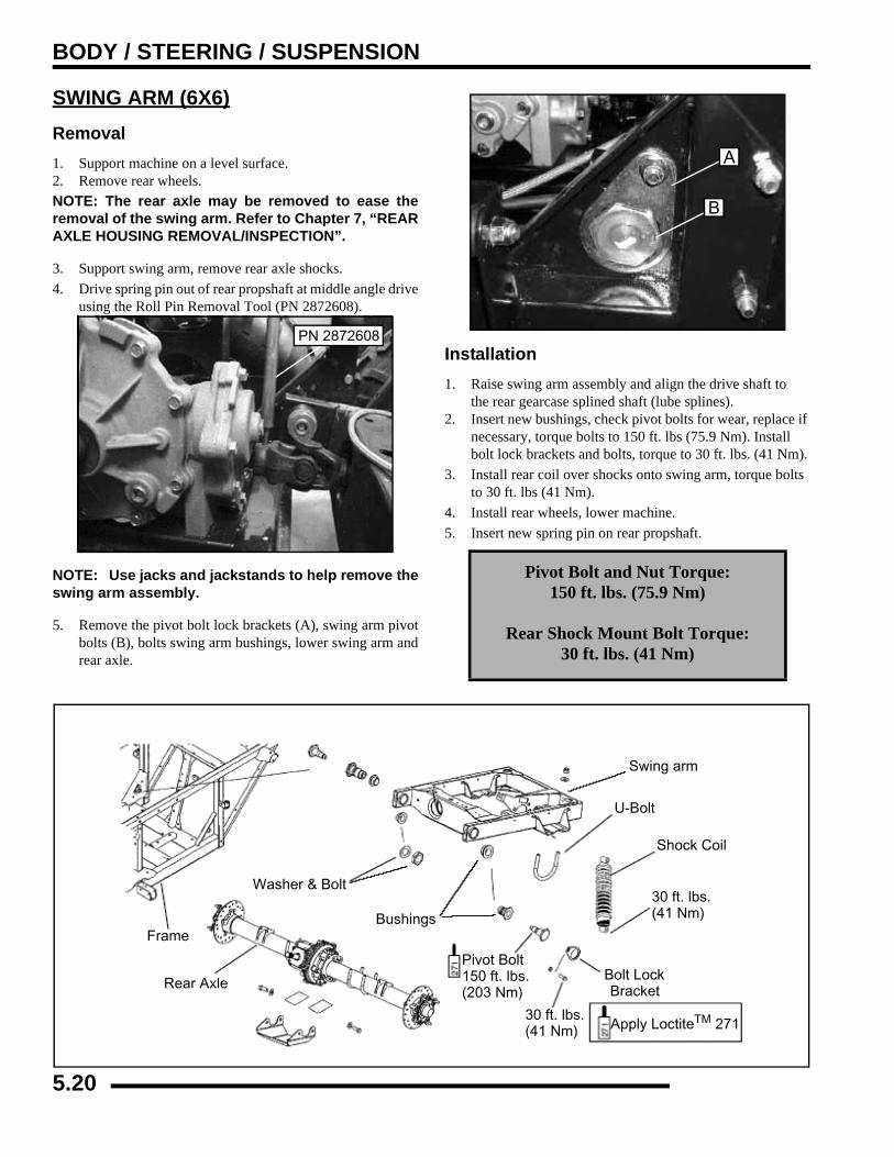
BODY / STEERING / SUSPENSION
SWING ARM (6X6)Removal1. Support machine on a level surface.2. Remove rear wheels.NOTE: The rear axle may be removed to ease theremoval of the swing arm. Refer to Chapter 7, “REARAXLE HOUSING REMOVAL/INSPECTION”.
3. Support swing arm, remove rear axle shocks.4. Drive spring pin out of rear propshaft at middle angle drive
using the Roll Pin Removal Tool (PN 2872608).
NOTE: Use jacks and jackstands to help remove theswing arm assembly.
5. Remove the pivot bolt lock brackets (A), swing arm pivotbolts (B), bolts swing arm bushings, lower swing arm andrear axle.
Installation1. Raise swing arm assembly and align the drive shaft to
the rear gearcase splined shaft (lube splines).2. Insert new bushings, check pivot bolts for wear, replace if
necessary, torque bolts to 150 ft. lbs (75.9 Nm). Install bolt lock brackets and bolts, torque to 30 ft. lbs. (41 Nm).
3. Install rear coil over shocks onto swing arm, torque bolts to 30 ft. lbs (41 Nm).
4. Install rear wheels, lower machine.5. Insert new spring pin on rear propshaft.
PN 2872608
Pivot Bolt and Nut Torque:150 ft. lbs. (75.9 Nm)
Rear Shock Mount Bolt Torque: 30 ft. lbs. (41 Nm)
A
B
Frame
Rear Axle
Washer & Bolt
Bushings
Swing arm
U-Bolt
Shock Coil
30 ft. lbs.(41 Nm)
Bolt LockBracket
Pivot Bolt150 ft. lbs.(203 Nm)
30 ft. lbs.(41 Nm) Apply LoctiteTM 271
5.20

BODY / STEERING / SUSPENSION
5
REAR DRIVE AXLE AND SWINGARM EXPLODED VIEW (6X6)
Vehicle Frame
Swing Arm
Rear Gearcase
Bolt & WasherRubber Pad
Retaining Ring Axle Tube Screw & Washer
Washer
Axle Tube
U - Bolt Nut & Washer
U- Bolt
Swing Arm Pivot Bolt
Grease Fitting
Swing Arm Bushing
Wheel
O - Ring
Jam Nut
150 ft. lbs.(203 Nm)
Bolt LockBracket
Bearing
60 ft. lbs. (81 Nm)
60 ft. lbs. (81 Nm)
Screw & Washer 60 ft. lbs. (81 Nm)
Axle
WheelBearing
Assembly
Skid Plate
Pivot Bushing
150 ft. lbs.(203 Nm)
30 ft. lbs.(40 Nm)
40 ft. lbs.(54 Nm)
Apply LoctiteTM 242
5.21
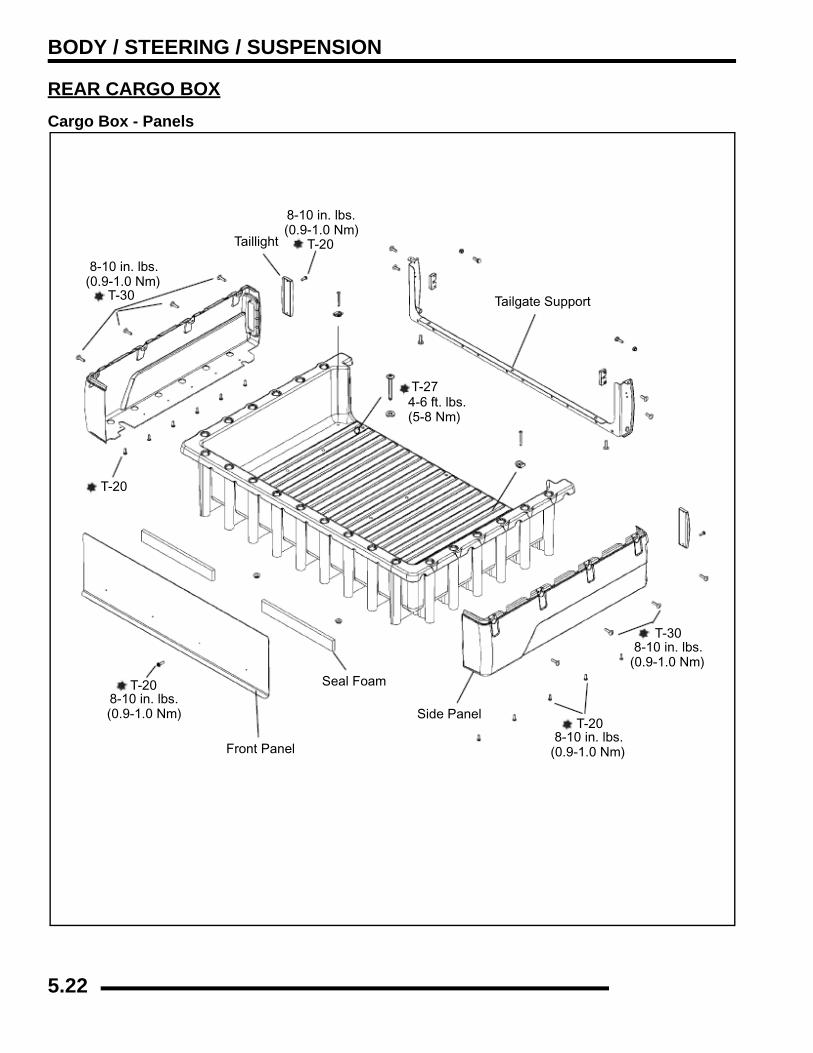
BODY / STEERING / SUSPENSION
REAR CARGO BOXCargo Box - Panels
Taillight
Tailgate Support
Seal Foam
Side Panel
Front Panel
T-27
8-10 in. lbs.(0.9-1.0 Nm)
T-30
T-30
8-10 in. lbs.(0.9-1.0 Nm)
8-10 in. lbs.(0.9-1.0 Nm)
T-20
8-10 in. lbs.(0.9-1.0 Nm)
T-20
T-20
8-10 in. lbs.(0.9-1.0 Nm)
T-20
4-6 ft. lbs.(5-8 Nm)
5.22
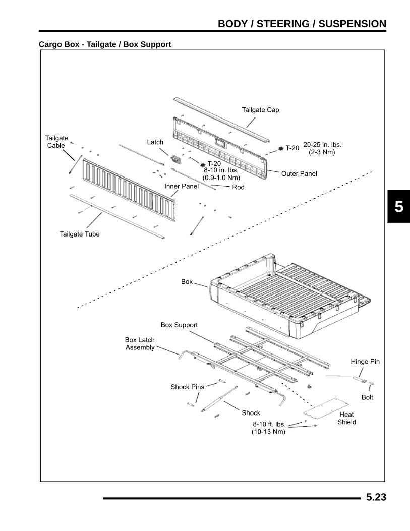
BODY / STEERING / SUSPENSION
5
Cargo Box - Tailgate / Box Support
Tailgate Cap
LatchTailgateCable
Tailgate Tube
Inner Panel Rod
Outer Panel
T-20
20-25 in. lbs.(2-3 Nm)
8-10 in. lbs.(0.9-1.0 Nm)
Box
Box Support
T-20
Box LatchAssembly
Shock Pins
Shock
8-10 ft. lbs.(10-13 Nm)
Heat
Bolt
Hinge Pin
Shield
5.23
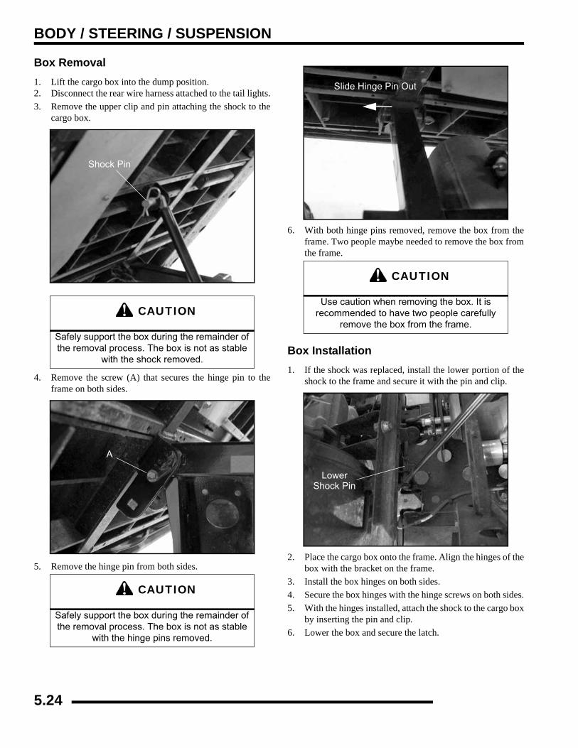
BODY / STEERING / SUSPENSION
Box Removal1. Lift the cargo box into the dump position.2. Disconnect the rear wire harness attached to the tail lights.3. Remove the upper clip and pin attaching the shock to the
cargo box.
4. Remove the screw (A) that secures the hinge pin to theframe on both sides.
5. Remove the hinge pin from both sides.
6. With both hinge pins removed, remove the box from theframe. Two people maybe needed to remove the box fromthe frame.
Box Installation1. If the shock was replaced, install the lower portion of the
shock to the frame and secure it with the pin and clip.
2. Place the cargo box onto the frame. Align the hinges of thebox with the bracket on the frame.
3. Install the box hinges on both sides.4. Secure the box hinges with the hinge screws on both sides.5. With the hinges installed, attach the shock to the cargo box
by inserting the pin and clip.6. Lower the box and secure the latch.
CAUTION
Safely support the box during the remainder of the removal process. The box is not as stable
with the shock removed.
CAUTION
Safely support the box during the remainder of the removal process. The box is not as stable
with the hinge pins removed.
Shock Pin
A
CAUTION
Use caution when removing the box. It is recommended to have two people carefully
remove the box from the frame.
Slide Hinge Pin Out
LowerShock Pin
5.24
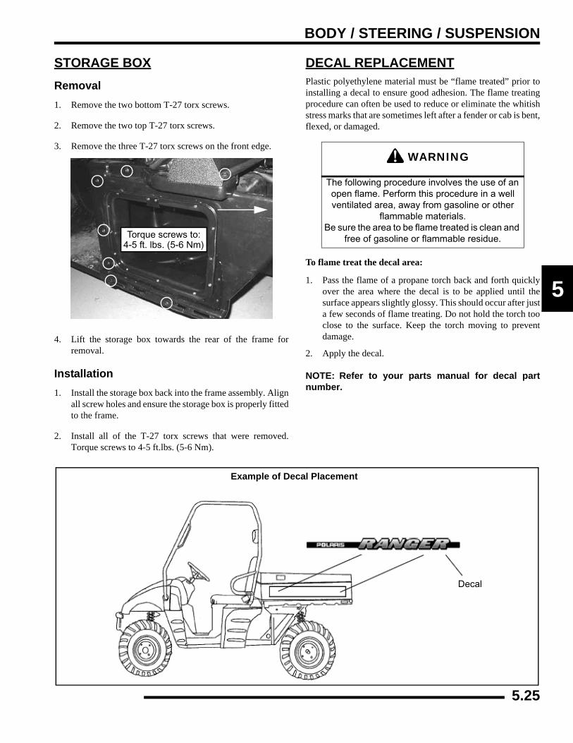
BODY / STEERING / SUSPENSION
5
STORAGE BOXRemoval1. Remove the two bottom T-27 torx screws.
2. Remove the two top T-27 torx screws.
3. Remove the three T-27 torx screws on the front edge.
4. Lift the storage box towards the rear of the frame forremoval.
Installation1. Install the storage box back into the frame assembly. Align
all screw holes and ensure the storage box is properly fittedto the frame.
2. Install all of the T-27 torx screws that were removed.Torque screws to 4-5 ft.lbs. (5-6 Nm).
DECAL REPLACEMENTPlastic polyethylene material must be “flame treated” prior toinstalling a decal to ensure good adhesion. The flame treatingprocedure can often be used to reduce or eliminate the whitishstress marks that are sometimes left after a fender or cab is bent,flexed, or damaged.
To flame treat the decal area:
1. Pass the flame of a propane torch back and forth quicklyover the area where the decal is to be applied until thesurface appears slightly glossy. This should occur after justa few seconds of flame treating. Do not hold the torch tooclose to the surface. Keep the torch moving to preventdamage.
2. Apply the decal.
NOTE: Refer to your parts manual for decal partnumber.
Torque screws to:4-5 ft. lbs. (5-6 Nm)
WARNING
The following procedure involves the use of an open flame. Perform this procedure in a well ventilated area, away from gasoline or other
flammable materials. Be sure the area to be flame treated is clean and
free of gasoline or flammable residue.
Example of Decal Placement
Decal
5.25
CLUTCHING
CHAPTER 6CLUTCHING
6
SPECIAL TOOLS AND SUPPLIES . . . . . . . . . . . . . . . . . . . . . . . . . . . . . . . . . . . . . . . . . . 6.2TORQUE SPECIFICATIONS. . . . . . . . . . . . . . . . . . . . . . . . . . . . . . . . . . . . . . . . . . . . . . . 6.2
PVT SYSTEM FASTENER TORQUES . . . . . . . . . . . . . . . . . . . . . . . . . . . . . . . . . . . . . . 6.2PVT SYSTEM OVERVIEW . . . . . . . . . . . . . . . . . . . . . . . . . . . . . . . . . . . . . . . . . . . . . . . . 6.2
GENERAL OPERATION. . . . . . . . . . . . . . . . . . . . . . . . . . . . . . . . . . . . . . . . . . . . . . . . . . 6.2DRIVE CLUTCH OPERATION . . . . . . . . . . . . . . . . . . . . . . . . . . . . . . . . . . . . . . . . . . . . . 6.2DRIVEN CLUTCH OPERATION. . . . . . . . . . . . . . . . . . . . . . . . . . . . . . . . . . . . . . . . . . . . 6.3MAINTENANCE / INSPECTION. . . . . . . . . . . . . . . . . . . . . . . . . . . . . . . . . . . . . . . . . . . . 6.3OVERHEATING / DIAGNOSIS. . . . . . . . . . . . . . . . . . . . . . . . . . . . . . . . . . . . . . . . . . . . . 6.4
PVT SYSTEM SERVICE . . . . . . . . . . . . . . . . . . . . . . . . . . . . . . . . . . . . . . . . . . . . . . . . . . 6.5PVT SEALING, GUARD, AND DUCTING COMPONENTS . . . . . . . . . . . . . . . . . . . . . . . 6.5DISASSEMBLY. . . . . . . . . . . . . . . . . . . . . . . . . . . . . . . . . . . . . . . . . . . . . . . . . . . . . . . . . 6.5ASSEMBLY . . . . . . . . . . . . . . . . . . . . . . . . . . . . . . . . . . . . . . . . . . . . . . . . . . . . . . . . . . . 6.6
DRIVE BELT . . . . . . . . . . . . . . . . . . . . . . . . . . . . . . . . . . . . . . . . . . . . . . . . . . . . . . . . . . . 6.7BELT DEFLECTION (TENSION) . . . . . . . . . . . . . . . . . . . . . . . . . . . . . . . . . . . . . . . . . . . 6.7BELT REMOVAL . . . . . . . . . . . . . . . . . . . . . . . . . . . . . . . . . . . . . . . . . . . . . . . . . . . . . . . 6.7BELT INSPECTION . . . . . . . . . . . . . . . . . . . . . . . . . . . . . . . . . . . . . . . . . . . . . . . . . . . . . 6.8BELT INSTALLATION . . . . . . . . . . . . . . . . . . . . . . . . . . . . . . . . . . . . . . . . . . . . . . . . . . . 6.9
CLUTCH ALIGNMENT / OFFSET . . . . . . . . . . . . . . . . . . . . . . . . . . . . . . . . . . . . . . . . . . . 6.9CLUTCH ALIGNMENT . . . . . . . . . . . . . . . . . . . . . . . . . . . . . . . . . . . . . . . . . . . . . . . . . . . 6.9CLUTCH OFFSET . . . . . . . . . . . . . . . . . . . . . . . . . . . . . . . . . . . . . . . . . . . . . . . . . . . . . 6.10
DRIVE CLUTCH SERVICE . . . . . . . . . . . . . . . . . . . . . . . . . . . . . . . . . . . . . . . . . . . . . . . 6.11SPRING SPECIFICATIONS . . . . . . . . . . . . . . . . . . . . . . . . . . . . . . . . . . . . . . . . . . . . . . 6.11SHIFT WEIGHTS . . . . . . . . . . . . . . . . . . . . . . . . . . . . . . . . . . . . . . . . . . . . . . . . . . . . . . 6.12EXPLODED VIEW . . . . . . . . . . . . . . . . . . . . . . . . . . . . . . . . . . . . . . . . . . . . . . . . . . . . . 6.13CLUTCH INSPECTION . . . . . . . . . . . . . . . . . . . . . . . . . . . . . . . . . . . . . . . . . . . . . . . . . 6.13CLUTCH DISASSEMBLY. . . . . . . . . . . . . . . . . . . . . . . . . . . . . . . . . . . . . . . . . . . . . . . . 6.14SPIDER REMOVAL . . . . . . . . . . . . . . . . . . . . . . . . . . . . . . . . . . . . . . . . . . . . . . . . . . . . 6.15ROLLER, PIN, AND THRUST WASHER INSPECTION. . . . . . . . . . . . . . . . . . . . . . . . . 6.15BUSHING SERVICE. . . . . . . . . . . . . . . . . . . . . . . . . . . . . . . . . . . . . . . . . . . . . . . . . . . . 6.16MOVEABLE SHEAVE - BUSHING REMOVAL . . . . . . . . . . . . . . . . . . . . . . . . . . . . . . . 6.16MOVEABLE SHEAVE - BUSHING INSTALLATION . . . . . . . . . . . . . . . . . . . . . . . . . . . 6.16CLUTCH COVER - BUSHING REMOVAL . . . . . . . . . . . . . . . . . . . . . . . . . . . . . . . . . . . 6.17CLUTCH COVER - BUSHING INSTALLATION . . . . . . . . . . . . . . . . . . . . . . . . . . . . . . . 6.17CLUTCH ASSEMBLY. . . . . . . . . . . . . . . . . . . . . . . . . . . . . . . . . . . . . . . . . . . . . . . . . . . 6.18
DRIVEN CLUTCH SERVICE. . . . . . . . . . . . . . . . . . . . . . . . . . . . . . . . . . . . . . . . . . . . . . 6.19EXPLODED VIEW . . . . . . . . . . . . . . . . . . . . . . . . . . . . . . . . . . . . . . . . . . . . . . . . . . . . . 6.19CLUTCH DISASSEMBLY / INSPECTION . . . . . . . . . . . . . . . . . . . . . . . . . . . . . . . . . . . 6.19CLUTCH ASSEMBLY. . . . . . . . . . . . . . . . . . . . . . . . . . . . . . . . . . . . . . . . . . . . . . . . . . . 6.21
TROUBLESHOOTING. . . . . . . . . . . . . . . . . . . . . . . . . . . . . . . . . . . . . . . . . . . . . . . . . . . 6.22
6.1
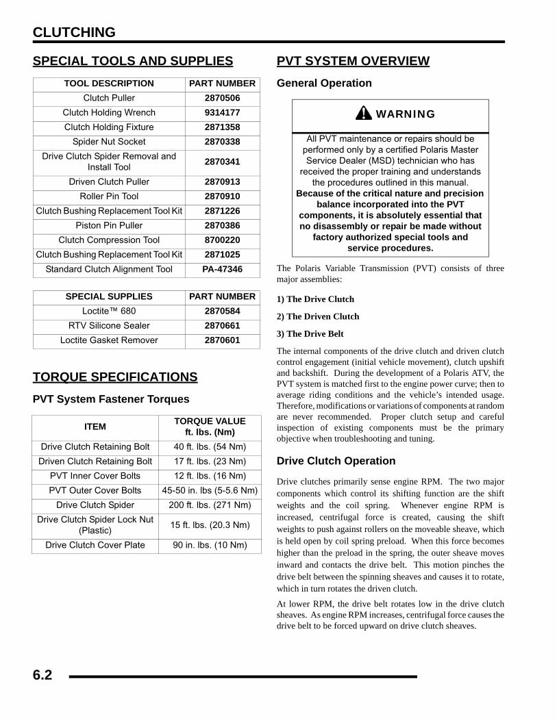
CLUTCHING
SPECIAL TOOLS AND SUPPLIES
TORQUE SPECIFICATIONSPVT System Fastener Torques
PVT SYSTEM OVERVIEWGeneral Operation
The Polaris Variable Transmission (PVT) consists of threemajor assemblies:
1) The Drive Clutch
2) The Driven Clutch
3) The Drive Belt
The internal components of the drive clutch and driven clutchcontrol engagement (initial vehicle movement), clutch upshiftand backshift. During the development of a Polaris ATV, thePVT system is matched first to the engine power curve; then toaverage riding conditions and the vehicle’s intended usage.Therefore, modifications or variations of components at randomare never recommended. Proper clutch setup and carefulinspection of existing components must be the primaryobjective when troubleshooting and tuning.
Drive Clutch Operation
Drive clutches primarily sense engine RPM. The two majorcomponents which control its shifting function are the shiftweights and the coil spring. Whenever engine RPM isincreased, centrifugal force is created, causing the shiftweights to push against rollers on the moveable sheave, whichis held open by coil spring preload. When this force becomeshigher than the preload in the spring, the outer sheave movesinward and contacts the drive belt. This motion pinches thedrive belt between the spinning sheaves and causes it to rotate,which in turn rotates the driven clutch.
At lower RPM, the drive belt rotates low in the drive clutchsheaves. As engine RPM increases, centrifugal force causes thedrive belt to be forced upward on drive clutch sheaves.
TOOL DESCRIPTION PART NUMBERClutch Puller 2870506
Clutch Holding Wrench 9314177Clutch Holding Fixture 2871358
Spider Nut Socket 2870338Drive Clutch Spider Removal and
Install Tool2870341
Driven Clutch Puller 2870913Roller Pin Tool 2870910
Clutch Bushing Replacement Tool Kit 2871226Piston Pin Puller 2870386
Clutch Compression Tool 8700220Clutch Bushing Replacement Tool Kit 2871025
Standard Clutch Alignment Tool PA-47346
SPECIAL SUPPLIES PART NUMBERLoctite™ 680 2870584
RTV Silicone Sealer 2870661Loctite Gasket Remover 2870601
ITEM TORQUE VALUEft. lbs. (Nm)
Drive Clutch Retaining Bolt 40 ft. lbs. (54 Nm)
Driven Clutch Retaining Bolt 17 ft. lbs. (23 Nm)
PVT Inner Cover Bolts 12 ft. lbs. (16 Nm)
PVT Outer Cover Bolts 45-50 in. lbs (5-5.6 Nm)
Drive Clutch Spider 200 ft. lbs. (271 Nm)
Drive Clutch Spider Lock Nut (Plastic)
15 ft. lbs. (20.3 Nm)
Drive Clutch Cover Plate 90 in. lbs. (10 Nm)
WARNING
All PVT maintenance or repairs should be performed only by a certified Polaris Master Service Dealer (MSD) technician who has
received the proper training and understands the procedures outlined in this manual.
Because of the critical nature and precision balance incorporated into the PVT
components, it is absolutely essential that no disassembly or repair be made without
factory authorized special tools and service procedures.
6.2

CLUTCHING
6
Driven Clutch Operation
Driven clutches primarily sense torque, opening and closingaccording to the forces applied to it from the drive belt and thetransmission input shaft. If the torque resistance at the trans-mission input shaft is greater than the load from the drive belt,the drive belt is kept at the outer diameter of the driven clutchsheaves.
As engine RPM and horsepower increase, the load from thedrive belt increases, resulting in the belt rotating up toward theouter diameter of the drive clutch sheaves and downward intothe sheaves of the driven clutch. This action, which increasesthe driven clutch speed, is called upshifting.
Should the throttle setting remain the same and the vehicle issubjected to a heavier load, the drive belt rotates back up towardthe outer diameter of the driven clutch and downward into thesheaves of the drive clutch. This action, which decreases thedriven clutch speed, is called backshifting.
In situations where loads vary (such as uphill and downhill) andthrottle settings are constant, the drive and driven clutches arecontinually shifting to maintain optimum engine RPM. At fullthrottle a perfectly matched PVT system should hold engineRPM at the peak of the power curve. This RPM should bemaintained during clutch upshift and backshift. In this respect,the PVT system is similar to a power governor. Rather than varythrottle position, as a conventional governor does, the PVTsystem changes engine load requirements by either upshifting orbackshifting.
Maintenance / InspectionUnder normal operation the PVT system will provide years oftrouble free operation. Periodic inspection and maintenance isrequired to keep the system operating at peak performance. Thefollowing list of items should be inspected and maintained toensure maximum performance and service life of PVTcomponents. Refer to the troubleshooting checklist at the end ofthis chapter for more information.
1. Belt Tension, Drive to Driven Clutch Offset, BeltWidth. See these sections later in chapter for each model.
2. Drive and Driven Clutch Buttons and Bushings, DriveClutch Shift Weights and Pins, Drive Clutch SpiderRollers and Roller Pins, Drive and Driven ClutchSprings. See these sections later in chapter.
3. Sheave Faces. Clean and inspect for wear.
4. PVT System Sealing. Refer to appropriate illustration onthe following pages. The PVT system is air cooled by finson the drive clutch stationary sheave. The fins create a lowpressure area in the crankcase casting, drawing air into thesystem through an intake duct. The opening for this intakeduct is located at a high point on the vehicle (location variesby model). The intake duct draws fresh air through a ventedcover. All connecting air ducts (as well as the inner andouter covers) must be properly sealed to ensure clean air isbeing used for cooling the PVT system and also to preventwater and other contaminants from entering the PVT area.This is especially critical on units subjected to frequentwater forging.
6.3
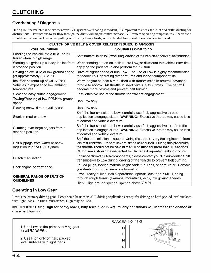
CLUTCHING
Overheating / DiagnosisDuring routine maintenance or whenever PVT system overheating is evident, it’s important to check the inlet and outlet ducting forobstructions. Obstructions to air flow through the ducts will significantly increase PVT system operating temperatures. The vehicleshould be operated in Low when pulling or plowing heavy loads, or if extended low speed operation is anticipated.
Operating in Low GearLow is the primary driving gear. Low should be used in ALL driving applications except for driving on hard packed level surfaceswith light loads. In this circumstance, High may be used.
IMPORTANT: Using High for heavy loads, hilly terrain, or in wet, muddy conditions will increase the chance ofdrive belt burning.
CLUTCH DRIVE BELT & COVER RELATED ISSUES: DIAGNOSISPossible Causes Solutions / What to do
Loading the vehicle into a truck or tall trailer when in high range.
Shift transmission to Low during loading of the vehicle to prevent belt burning.
Starting out going up a steep incline from a stopped position.
When starting out on an incline, use Low, or dismount the vehicle after first applying the park brake and perform the “K” turn.
Driving at low RPM or low ground speed (at approximately 3-7 MPH).
Drive at higher speed or use Low. The use of Low is highly recommended for cooler PVT operating temperatures and longer component life.
Insufficient warm-up of Utility Task Vehicles™ exposed to low ambient temperatures.
Warm engine at least 5 min., then with transmission in neutral, advance throttle to approx. 1/8 throttle in short bursts, 5 to 7 times. The belt will become more flexible and prevent belt burning.
Slow and easy clutch engagement. Fast, effective use of the throttle for efficient engagement.Towing/Pushing at low RPM/low ground speed.
Use Low only.
Plowing snow, dirt, etc./utility use. Use Low only.
Stuck in mud or snow.Shift the transmission to Low, carefully use fast, aggressive throttle application to engage clutch. WARNING: Excessive throttle may cause loss of control and vehicle overturn.
Climbing over large objects from a stopped position.
Shift the transmission to Low, carefully use fast, aggressive, brief throttle application to engage clutch. WARNING: Excessive throttle may cause loss of control and vehicle overturn.
Belt slippage from water or snow ingestion into the PVT system.
Shift the transmission to neutral. Using the throttle, vary the engine rpm from idle to full throttle. Repeat several times as required. During this procedure, the throttle should not be held at the full position for more than 10 seconds. Clutch seals should be inspected for damage if repeated leaking occurs.
Clutch malfunction.For inspection of clutch components, please contact your Polaris dealer. Shift transmission to Low during loading of the vehicle to prevent belt burning.
Poor engine performance.Fouled plugs, foreign material in gas tank, fuel lines, or carburetor. Contact you dealer for further service information.
GENERAL RANGE OPERATION GUIDELINES:
Low: Heavy pulling, basic operational speeds less than 7 MPH, riding through rough terrain (swamps, mountains, ect.), low ground speeds.High: High ground speeds, speeds above 7 MPH.
L
H
N
R
1. Use Low as the primary driving gearfor all RANGERs.
2. Use High only on hard packed,level surfaces with light loads.
RANGER 4X4 / 6X6
6.4

CLUTCHING
6
PVT SYSTEM SERVICEPVT Sealing, Guard, and Ducting Components
DisassemblySome fasteners and procedures will vary. Refer to theappropriate parts manual for proper fasteners and fastenerplacement.
1. Remove seat.2. Remove the LH storage box to gain access to PVT outer
cover. (See Chapter 5 for removal)3. Remove PVT air outlet duct hose.4. Remove outer PVT cover screws.5. Mark the drive belt direction of rotation and remove drive
belt. See “Drive Belt Removal”.
6. Install the Drive Clutch Holder (PN 9314177) (A).
7. Remove drive clutch retaining bolt and remove drive clutchusing the Drive Clutch Puller (PN 2870506) (B).
8. Remove the driven clutch retaining bolt and driven clutch.
Inner Cover
Clutch Outlet Duct
Clamps
Inner Cover Seal
Retainer
Outer Cover Seal
Cover Bolts PVT Outer Cover
SEALING AND DUCTING COMPONENTS
A
B
Drive Clutch Puller (PN 2870506)
Drive Clutch Holder (PN 9314177)
Retaining Bolt
6.5
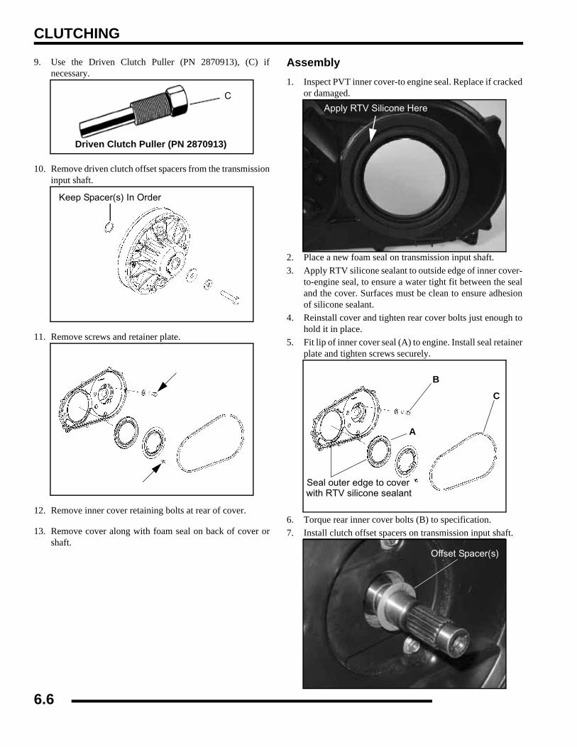
CLUTCHING
9. Use the Driven Clutch Puller (PN 2870913), (C) ifnecessary.
10. Remove driven clutch offset spacers from the transmissioninput shaft.
11. Remove screws and retainer plate.
12. Remove inner cover retaining bolts at rear of cover.
13. Remove cover along with foam seal on back of cover orshaft.
Assembly1. Inspect PVT inner cover-to engine seal. Replace if cracked
or damaged.
2. Place a new foam seal on transmission input shaft.3. Apply RTV silicone sealant to outside edge of inner cover-
to-engine seal, to ensure a water tight fit between the sealand the cover. Surfaces must be clean to ensure adhesionof silicone sealant.
4. Reinstall cover and tighten rear cover bolts just enough tohold it in place.
5. Fit lip of inner cover seal (A) to engine. Install seal retainerplate and tighten screws securely.
6. Torque rear inner cover bolts (B) to specification.7. Install clutch offset spacers on transmission input shaft.
C
Driven Clutch Puller (PN 2870913)
Keep Spacer(s) In Order
Apply RTV Silicone Here
B
C
A
Seal outer edge to coverwith RTV silicone sealant
Offset Spacer(s)
6.6
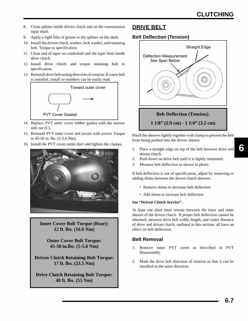
CLUTCHING
6
8. Clean splines inside driven clutch and on the transmissioninput shaft.
9. Apply a light film of grease to the splines on the shaft.10. Install the driven clutch, washer, lock washer, and retaining
bolt. Torque to specification.11. Clean end of taper on crankshaft and the taper bore inside
drive clutch.12. Install drive clutch and torque retaining bolt to
specification.13. Reinstall drive belt noting direction of rotation. If a new belt
is installed, install so numbers can be easily read.
14. Replace PVT outer cover rubber gasket with the narrowside out (C).
15. Reinstall PVT outer cover and secure with screws Torqueto 45-50 in. lbs. (5-5.6 Nm).
16. Install the PVT cover outlet duct and tighten the clamps.
DRIVE BELTBelt Deflection (Tension)
Pinch the sheaves lightly together with clamp to prevent the beltfrom being pushed into the driven sheave.
1. Place a straight edge on top of the belt between drive anddriven clutch.
2. Push down on drive belt until it is lightly tensioned.3. Measure belt deflection as shown in photo.
If belt deflection is out of specification, adjust by removing oradding shims between the driven clutch sheaves.
• Remove shims to decrease belt deflection
• Add shims to increase belt deflection
See “Driven Clutch Service”.
At least one shim must remain between the inner and outersheave of the driven clutch. If proper belt deflection cannot beobtained, measure drive belt width, length, and center distanceof drive and driven clutch, outlined in this section; all have aneffect on belt deflection.
Belt Removal1. Remove outer PVT cover as described in PVT
Disassembly.
2. Mark the drive belt direction of rotation so that it can beinstalled in the same direction.
Inner Cover Bolt Torque (Rear):12 ft. lbs. (16.6 Nm)
Outer Cover Bolt Torque:45-50 in.lbs. (5-5.6 Nm)
Driven Clutch Retaining Bolt Torque:17 ft. lbs. (23.5 Nm)
Drive Clutch Retaining Bolt Torque:40 ft. lbs. (55 Nm)
PVT Cover Gasket
Toward outer cover
Belt Deflection (Tension):
1 1/8” (2.9 cm) - 1 1/4” (3.2 cm)
Straight Edge
Deflection MeasurementSee Spec Below
6.7

CLUTCHING
NOTE: Belt is normally positioned so that partnumbers are easily read.
3. To remove drive belt, put transmission in gear, apply brake,pull upward and rearward on belt to open driven clutchsheaves, pull out and down on belt to slip over the drivenclutch outer sheave.
Belt Inspection
1. Measure belt width and replace if worn severely.Generally, belt should be replaced if clutches can nolonger be adjusted to provide proper belt deflection.
• The top edges have been trimmed on some drive belts.It will be necessary to project the side profiles andmeasure from corner to corner.
• Place a straight edge on each side of the drive belt.
• Place another straight edge on top of belt.
• Measure the distance where the side straight edgesintersect the top.
2. Inspect belt for loose cords, missing cogs, cracks,abrasions, thin spots, or excessive wear. Replace ifnecessary.
3. Inspect belt for hour glassing (extreme circular wear in atleast one spot and on both sides of the belt). Hour glassingoccurs when the drive train does not move and the driveclutch engages the belt.
4. Measure belt length with a tape measure around the outercircumference of the belt. Belts which measure longer thannominal length may require driven shimming or engineadjustment for a longer center distance to obtain proper beltdeflection. Belts which measure shorter than nominallength may require driven shimming or a shorter centerdistance. Remember, proper belt deflection is the desiredgoal - not a specific center distance.
5. Replace belt if worn past the wear limit. Belts with thinspots, burn marks, etc., should be replaced to eliminatenoise, vibration, or erratic PVT operation. SeeTroubleshooting Chart at the end of this chapter forpossible causes.
Belt WidthNew: 1.188” (3.02 cm)
Wear Limit: 1.157 (2.94 cm)
Belt Width
Clutch Center Distance:10” + .1/-.05 (254 + 2.5 / -1.3 mm)
Belt Outer CircumferenceNew: 41.225” (104.71 cm)
Wear Limit: 41.413” (105.19 cm)
CenterDistance
6.8
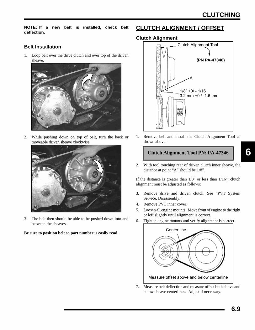
CLUTCHING
6
NOTE: If a new belt is installed, check beltdeflection.
Belt Installation1. Loop belt over the drive clutch and over top of the driven
sheave.
2. While pushing down on top of belt, turn the back ormoveable driven sheave clockwise.
3. The belt then should be able to be pushed down into andbetween the sheaves.
Be sure to position belt so part number is easily read.
CLUTCH ALIGNMENT / OFFSETClutch Alignment
1. Remove belt and install the Clutch Alignment Tool asshown above.
2. With tool touching rear of driven clutch inner sheave, thedistance at point “A” should be 1/8".
If the distance is greater than 1/8" or less than 1/16", clutchalignment must be adjusted as follows:
3. Remove drive and driven clutch. See “PVT SystemService, Disassembly.”
4. Remove PVT inner cover.5. Loosen all engine mounts. Move front of engine to the right
or left slightly until alignment is correct.6. Tighten engine mounts and verify alignment is correct.
7. Measure belt deflection and measure offset both above andbelow sheave centerlines. Adjust if necessary.
Clutch Alignment Tool PN: PA-47346
Clutch Alignment Tool
A
1/8” +0/ - 1/163.2 mm +0 / -1.6 mm
(PN PA-47346)
Measure offset above and below centerline
Center line
6.9

CLUTCHING
NOTE: On some models, minor adjustments can bemade by adding shims between the frame and frontlower left engine mount to increase the distance atpoint “A”. If a shim is present, it can be removed todecrease the distance at point “A”.
Clutch OffsetIMPORTANT: Inspect clutch alignment and centerdistance before adjusting offset.
1. Install clutch alignment tool as shown.
Offset is correct when rear of tool contacts rear of inner sheavewith driven clutch pushed completely inward on shaft and bolttorqued. Adjust offset by adding or removing spacer washersbetween back of driven clutch and spacer as shown.
Shim Kit PN: 2200126
Spacer Washer PN: 7556401
Clutch Alignment Toolshould contact rear edgeof driven clutch sheave
To adjust, add or removewashers from behind thedriven clutch
Driven Clutch Offset
6.10
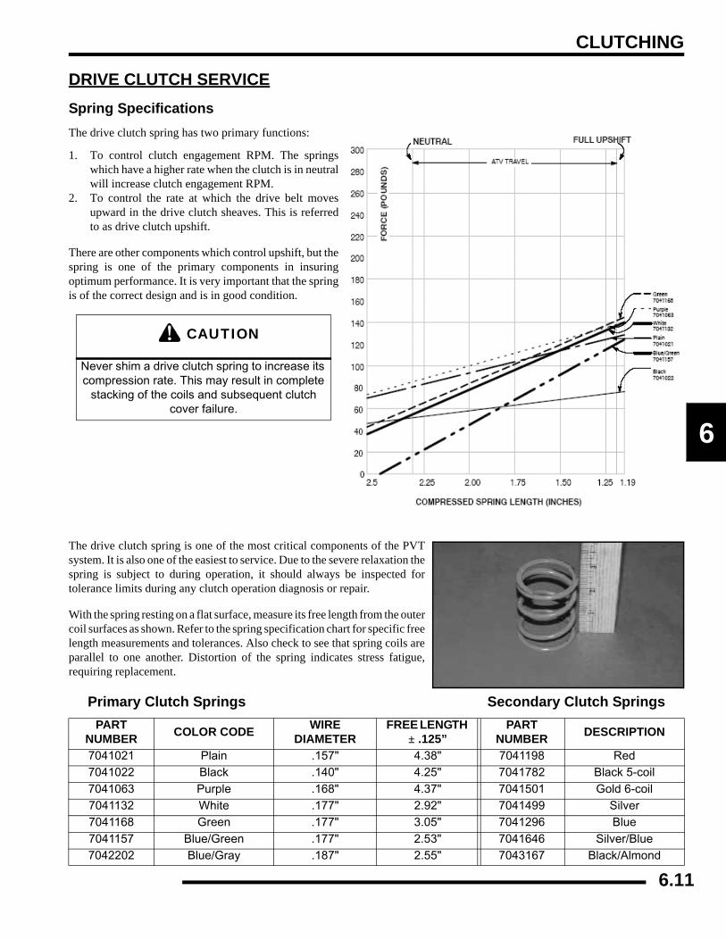
CLUTCHING
6
DRIVE CLUTCH SERVICESpring SpecificationsThe drive clutch spring has two primary functions:
1. To control clutch engagement RPM. The springswhich have a higher rate when the clutch is in neutralwill increase clutch engagement RPM.
2. To control the rate at which the drive belt movesupward in the drive clutch sheaves. This is referredto as drive clutch upshift.
There are other components which control upshift, but thespring is one of the primary components in insuringoptimum performance. It is very important that the springis of the correct design and is in good condition.
The drive clutch spring is one of the most critical components of the PVTsystem. It is also one of the easiest to service. Due to the severe relaxation thespring is subject to during operation, it should always be inspected fortolerance limits during any clutch operation diagnosis or repair.
With the spring resting on a flat surface, measure its free length from the outercoil surfaces as shown. Refer to the spring specification chart for specific freelength measurements and tolerances. Also check to see that spring coils areparallel to one another. Distortion of the spring indicates stress fatigue,requiring replacement.
CAUTION
Never shim a drive clutch spring to increase its compression rate. This may result in complete
stacking of the coils and subsequent clutch cover failure.
Primary Clutch Springs Secondary Clutch SpringsPART
NUMBER COLOR CODE WIREDIAMETER
FREE LENGTH ± .125”
PARTNUMBER DESCRIPTION
7041021 Plain .157" 4.38" 7041198 Red7041022 Black .140" 4.25" 7041782 Black 5-coil7041063 Purple .168" 4.37" 7041501 Gold 6-coil7041132 White .177" 2.92" 7041499 Silver7041168 Green .177" 3.05" 7041296 Blue7041157 Blue/Green .177" 2.53" 7041646 Silver/Blue7042202 Blue/Gray .187" 2.55" 7043167 Black/Almond
6.11
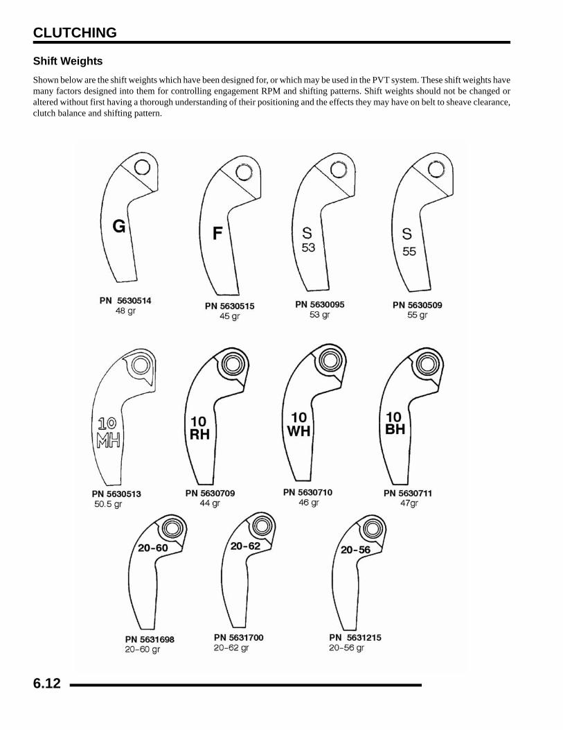
CLUTCHING
Shift WeightsShown below are the shift weights which have been designed for, or which may be used in the PVT system. These shift weights havemany factors designed into them for controlling engagement RPM and shifting patterns. Shift weights should not be changed oraltered without first having a thorough understanding of their positioning and the effects they may have on belt to sheave clearance,clutch balance and shifting pattern.
6.12
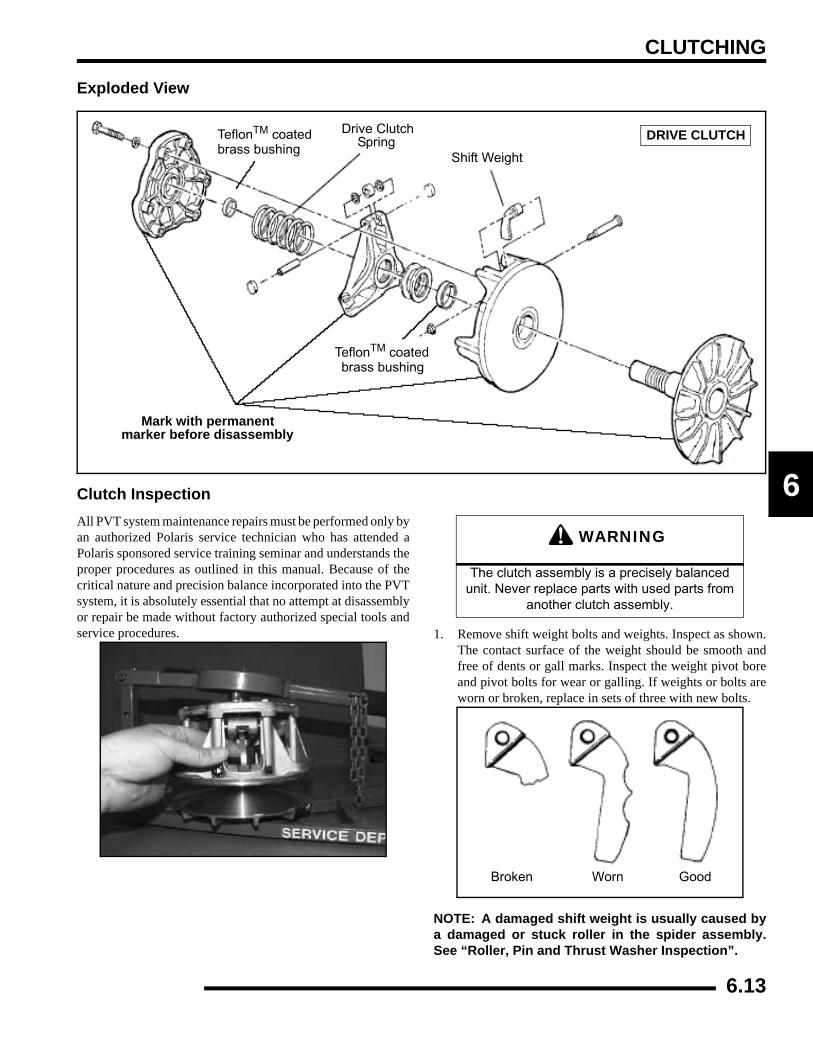
CLUTCHING
6
Exploded View
Clutch InspectionAll PVT system maintenance repairs must be performed only byan authorized Polaris service technician who has attended aPolaris sponsored service training seminar and understands theproper procedures as outlined in this manual. Because of thecritical nature and precision balance incorporated into the PVTsystem, it is absolutely essential that no attempt at disassemblyor repair be made without factory authorized special tools andservice procedures. 1. Remove shift weight bolts and weights. Inspect as shown.
The contact surface of the weight should be smooth andfree of dents or gall marks. Inspect the weight pivot boreand pivot bolts for wear or galling. If weights or bolts areworn or broken, replace in sets of three with new bolts.
NOTE: A damaged shift weight is usually caused bya damaged or stuck roller in the spider assembly.See “Roller, Pin and Thrust Washer Inspection”.
TeflonTM coatedbrass bushing
Shift Weight
Drive ClutchSpring
Mark with permanentmarker before disassembly
DRIVE CLUTCH
TeflonTM coatedbrass bushing
WARNING
The clutch assembly is a precisely balanced unit. Never replace parts with used parts from
another clutch assembly.
Broken Worn Good
6.13
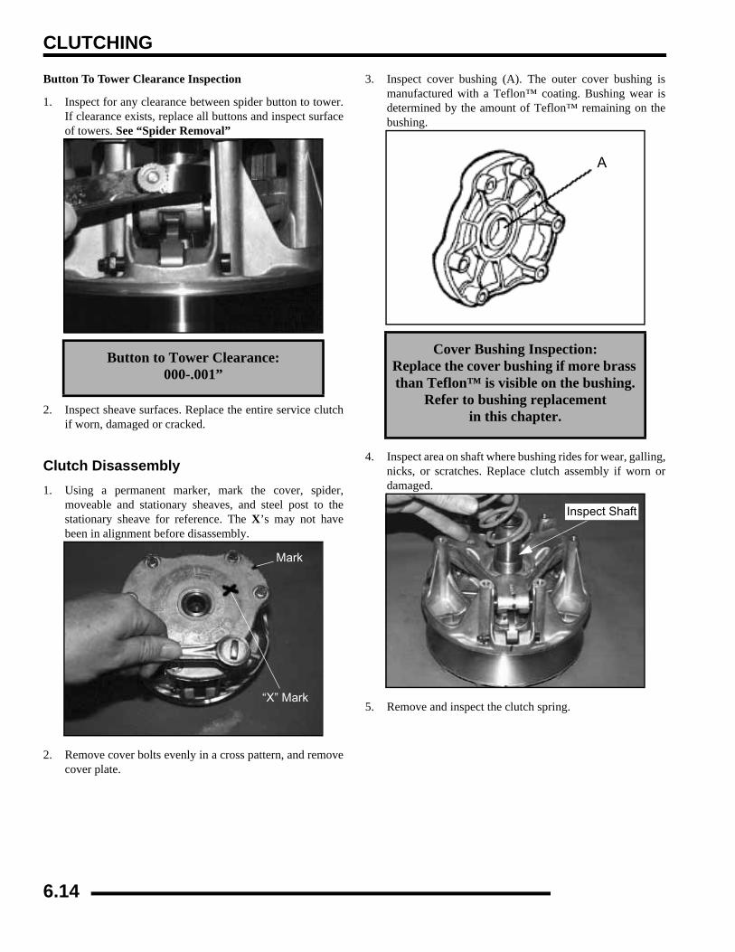
CLUTCHING
Button To Tower Clearance Inspection
1. Inspect for any clearance between spider button to tower.If clearance exists, replace all buttons and inspect surfaceof towers. See “Spider Removal”
2. Inspect sheave surfaces. Replace the entire service clutchif worn, damaged or cracked.
Clutch Disassembly1. Using a permanent marker, mark the cover, spider,
moveable and stationary sheaves, and steel post to thestationary sheave for reference. The X’s may not havebeen in alignment before disassembly.
2. Remove cover bolts evenly in a cross pattern, and removecover plate.
3. Inspect cover bushing (A). The outer cover bushing ismanufactured with a Teflon™ coating. Bushing wear isdetermined by the amount of Teflon™ remaining on thebushing.
4. Inspect area on shaft where bushing rides for wear, galling,nicks, or scratches. Replace clutch assembly if worn ordamaged.
5. Remove and inspect the clutch spring.
Button to Tower Clearance:000-.001”
Mark
“X” Mark
Cover Bushing Inspection:Replace the cover bushing if more brass than Teflon™ is visible on the bushing.
Refer to bushing replacement in this chapter.
A
Inspect Shaft
6.14
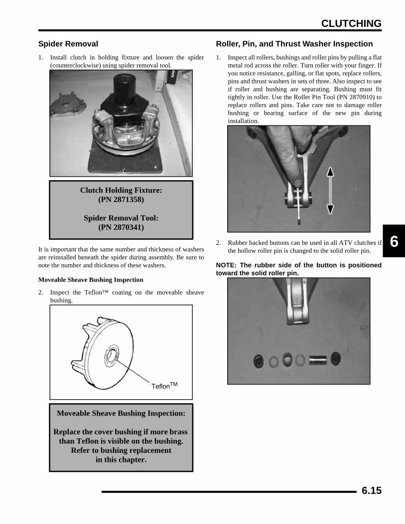
CLUTCHING
6
Spider Removal1. Install clutch in holding fixture and loosen the spider
(counterclockwise) using spider removal tool.
It is important that the same number and thickness of washersare reinstalled beneath the spider during assembly. Be sure tonote the number and thickness of these washers.
Moveable Sheave Bushing Inspection
2. Inspect the Teflon™ coating on the moveable sheavebushing.
Roller, Pin, and Thrust Washer Inspection1. Inspect all rollers, bushings and roller pins by pulling a flat
metal rod across the roller. Turn roller with your finger. Ifyou notice resistance, galling, or flat spots, replace rollers,pins and thrust washers in sets of three. Also inspect to seeif roller and bushing are separating. Bushing must fittightly in roller. Use the Roller Pin Tool (PN 2870910) toreplace rollers and pins. Take care not to damage rollerbushing or bearing surface of the new pin duringinstallation.
2. Rubber backed buttons can be used in all ATV clutches ifthe hollow roller pin is changed to the solid roller pin.
NOTE: The rubber side of the button is positionedtoward the solid roller pin.
Clutch Holding Fixture:(PN 2871358)
Spider Removal Tool:(PN 2870341)
Moveable Sheave Bushing Inspection:
Replace the cover bushing if more brass than Teflon is visible on the bushing.
Refer to bushing replacement in this chapter.
TeflonTM
6.15
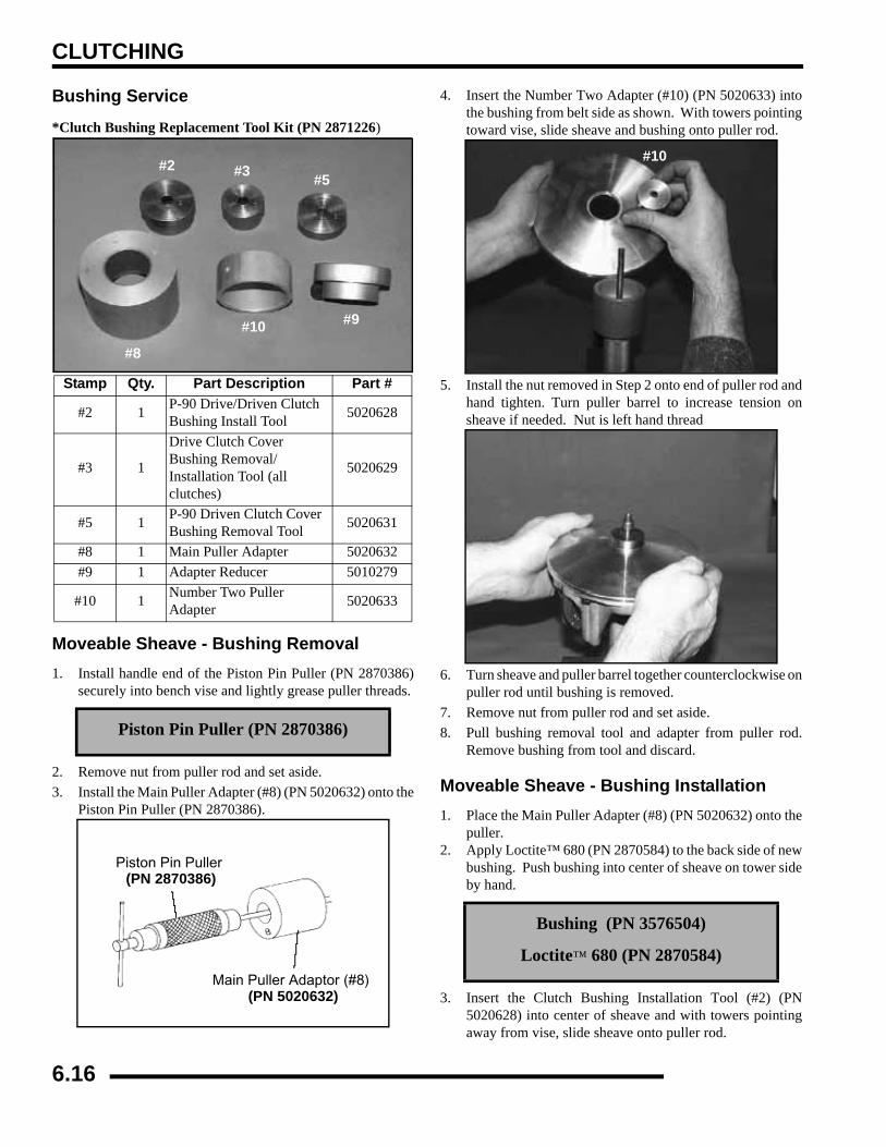
CLUTCHING
Bushing Service
*Clutch Bushing Replacement Tool Kit (PN 2871226)
Moveable Sheave - Bushing Removal1. Install handle end of the Piston Pin Puller (PN 2870386)
securely into bench vise and lightly grease puller threads.
2. Remove nut from puller rod and set aside.3. Install the Main Puller Adapter (#8) (PN 5020632) onto the
Piston Pin Puller (PN 2870386).
4. Insert the Number Two Adapter (#10) (PN 5020633) intothe bushing from belt side as shown. With towers pointingtoward vise, slide sheave and bushing onto puller rod.
5. Install the nut removed in Step 2 onto end of puller rod andhand tighten. Turn puller barrel to increase tension onsheave if needed. Nut is left hand thread
6. Turn sheave and puller barrel together counterclockwise onpuller rod until bushing is removed.
7. Remove nut from puller rod and set aside.8. Pull bushing removal tool and adapter from puller rod.
Remove bushing from tool and discard.
Moveable Sheave - Bushing Installation1. Place the Main Puller Adapter (#8) (PN 5020632) onto the
puller.2. Apply Loctite™ 680 (PN 2870584) to the back side of new
bushing. Push bushing into center of sheave on tower sideby hand.
3. Insert the Clutch Bushing Installation Tool (#2) (PN5020628) into center of sheave and with towers pointingaway from vise, slide sheave onto puller rod.
Stamp Qty. Part Description Part #
#2 1 P-90 Drive/Driven Clutch Bushing Install Tool 5020628
#3 1
Drive Clutch Cover Bushing Removal/Installation Tool (all clutches)
5020629
#5 1 P-90 Driven Clutch Cover Bushing Removal Tool 5020631
#8 1 Main Puller Adapter 5020632#9 1 Adapter Reducer 5010279
#10 1 Number Two Puller Adapter 5020633
Piston Pin Puller (PN 2870386)
#2 #3 #5
#8
#9#10
Piston Pin Puller (PN 2870386)
Main Puller Adaptor (#8) (PN 5020632)
Bushing (PN 3576504)
Loctite™ 680 (PN 2870584)
#10
6.16
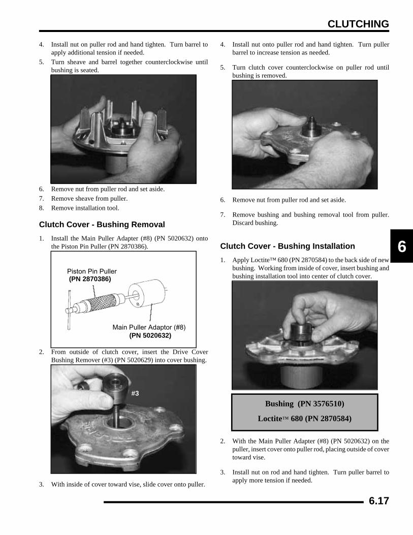
CLUTCHING
6
4. Install nut on puller rod and hand tighten. Turn barrel toapply additional tension if needed.
5. Turn sheave and barrel together counterclockwise untilbushing is seated.
6. Remove nut from puller rod and set aside.7. Remove sheave from puller.8. Remove installation tool.
Clutch Cover - Bushing Removal1. Install the Main Puller Adapter (#8) (PN 5020632) onto
the Piston Pin Puller (PN 2870386).
2. From outside of clutch cover, insert the Drive CoverBushing Remover (#3) (PN 5020629) into cover bushing.
3. With inside of cover toward vise, slide cover onto puller.
4. Install nut onto puller rod and hand tighten. Turn pullerbarrel to increase tension as needed.
5. Turn clutch cover counterclockwise on puller rod untilbushing is removed.
6. Remove nut from puller rod and set aside.
7. Remove bushing and bushing removal tool from puller.Discard bushing.
Clutch Cover - Bushing Installation1. Apply Loctite™ 680 (PN 2870584) to the back side of new
bushing. Working from inside of cover, insert bushing andbushing installation tool into center of clutch cover.
2. With the Main Puller Adapter (#8) (PN 5020632) on thepuller, insert cover onto puller rod, placing outside of covertoward vise.
3. Install nut on rod and hand tighten. Turn puller barrel toapply more tension if needed.
Piston Pin Puller (PN 2870386)
Main Puller Adaptor (#8) (PN 5020632)
#3Bushing (PN 3576510)
Loctite™ 680 (PN 2870584)
6.17
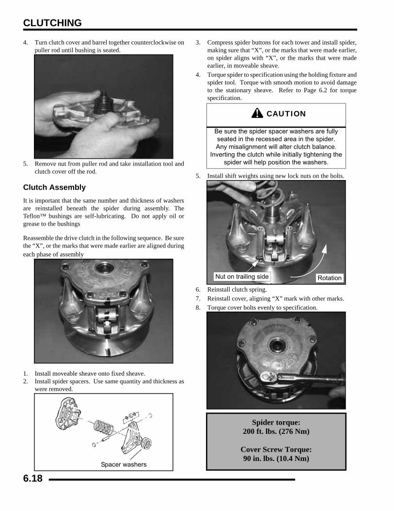
CLUTCHING
4. Turn clutch cover and barrel together counterclockwise onpuller rod until bushing is seated.
5. Remove nut from puller rod and take installation tool andclutch cover off the rod.
Clutch AssemblyIt is important that the same number and thickness of washersare reinstalled beneath the spider during assembly. TheTeflon™ bushings are self-lubricating. Do not apply oil orgrease to the bushings
Reassemble the drive clutch in the following sequence. Be surethe “X”, or the marks that were made earlier are aligned duringeach phase of assembly
1. Install moveable sheave onto fixed sheave.2. Install spider spacers. Use same quantity and thickness as
were removed.
3. Compress spider buttons for each tower and install spider,making sure that “X”, or the marks that were made earlier,on spider aligns with “X”, or the marks that were madeearlier, in moveable sheave.
4. Torque spider to specification using the holding fixture andspider tool. Torque with smooth motion to avoid damageto the stationary sheave. Refer to Page 6.2 for torquespecification.
5. Install shift weights using new lock nuts on the bolts.
6. Reinstall clutch spring.7. Reinstall cover, aligning “X” mark with other marks.8. Torque cover bolts evenly to specification.
Spacer washers
CAUTION
Be sure the spider spacer washers are fully seated in the recessed area in the spider. Any misalignment will alter clutch balance.
Inverting the clutch while initially tightening the spider will help position the washers.
Spider torque:200 ft. lbs. (276 Nm)
Cover Screw Torque:90 in. lbs. (10.4 Nm)
RotationNut on trailing side
6.18
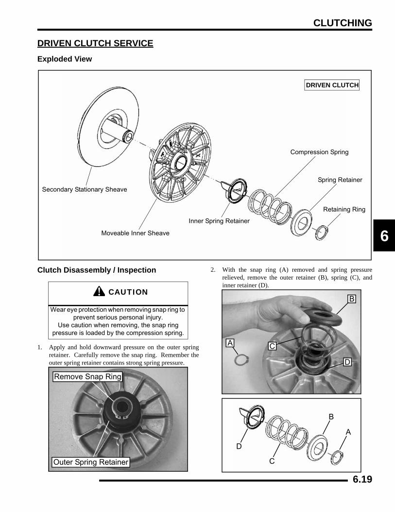
CLUTCHING
6
DRIVEN CLUTCH SERVICEExploded View
Clutch Disassembly / Inspection
1. Apply and hold downward pressure on the outer springretainer. Carefully remove the snap ring. Remember theouter spring retainer contains strong spring pressure.
2. With the snap ring (A) removed and spring pressurerelieved, remove the outer retainer (B), spring (C), andinner retainer (D).
Secondary Stationary Sheave
Moveable Inner Sheave
Inner Spring Retainer
DRIVEN CLUTCH
Compression Spring
Spring Retainer
Retaining Ring
CAUTION
Wear eye protection when removing snap ring to prevent serious personal injury.
Use caution when removing, the snap ring pressure is loaded by the compression spring.
Remove Snap Ring
Outer Spring Retainer
B
A C
D
A
B
C
D
6.19
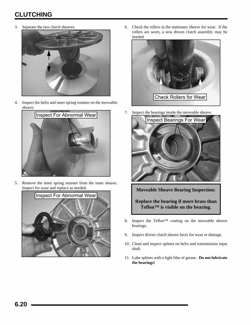
CLUTCHING
3. Separate the two clutch sheaves.
4. Inspect the helix and inner spring retainer on the moveablesheave.
5. Remove the inner spring retainer from the inner sheave.Inspect for wear and replace as needed.
6. Check the rollers in the stationary sheave for wear. If therollers are worn, a new driven clutch assembly may beneeded.
7. Inspect the bearings inside the moveable sheave.
8. Inspect the Teflon™ coating on the moveable sheavebearings.
9. Inspect driven clutch sheave faces for wear or damage.
10. Clean and inspect splines on helix and transmission inputshaft.
11. Lube splines with a light film of grease. Do not lubricatethe bearings!
Inspect For Abnormal Wear
Inspect For Abnormal WearMoveable Sheave Bearing Inspection:
Replace the bearing if more brass than Teflon™ is visible on the bearing.
Check Rollers for Wear
Inspect Bearings For Wear
6.20
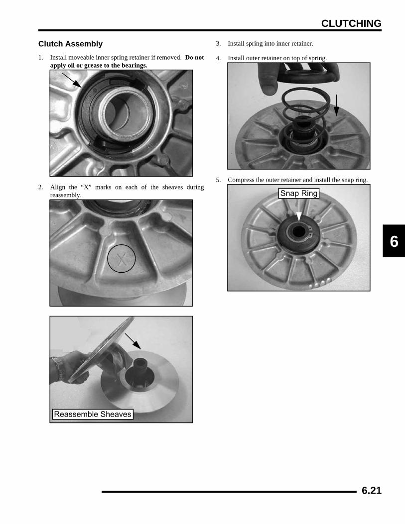
CLUTCHING
6
Clutch Assembly1. Install moveable inner spring retainer if removed. Do not
apply oil or grease to the bearings.
2. Align the “X” marks on each of the sheaves duringreassembly.
3. Install spring into inner retainer.
4. Install outer retainer on top of spring.
5. Compress the outer retainer and install the snap ring.
Reassemble Sheaves
Snap Ring
6.21
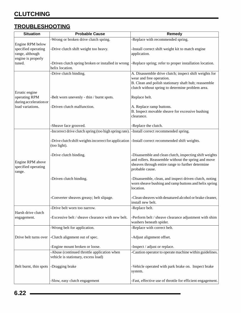
CLUTCHING
TROUBLESHOOTINGSituation Probable Cause Remedy
Engine RPM below specified operating range, although engine is properly tuned.
-Wrong or broken drive clutch spring.
-Drive clutch shift weight too heavy.
-Driven clutch spring broken or installed in wrong helix location.
-Replace with recommended spring.
-Install correct shift weight kit to match engine application.
-Replace spring; refer to proper installation location.
Erratic engine operating RPM during acceleration or load variations.
-Drive clutch binding.
-Belt worn unevenly - thin / burnt spots.
-Driven clutch malfunction.
-Sheave face grooved.
A. Disassemble drive clutch; inspect shift weights for wear and free operation.B. Clean and polish stationary shaft hub; reassemble clutch without spring to determine problem area.
Replace belt.
A. Replace ramp buttons.B. Inspect movable sheave for excessive bushing clearance.
-Replace the clutch.
Engine RPM above specified operating range.
-Incorrect drive clutch spring (too high spring rate).
-Drive clutch shift weights incorrect for application (too light).
-Drive clutch binding.
-Driven clutch binding.
-Converter sheaves greasy; belt slipage.
-Install correct recommended spring.
-Install correct recommended shift weights.
-Disassemble and clean clutch, inspecting shift weights and rollers. Reassemble without the spring and move sheaves through entire range to further determine probable cause.
-Disassemble, clean, and inspect driven clutch, noting worn sheave bushing and ramp buttons and helix spring location.
-Clean sheaves with denatured alcohol or brake cleaner, install new belt.
Harsh drive clutch engagement.
-Drive belt worn too narrow.
-Excessive belt / sheave clearance with new belt.
-Replace belt.
-Perform belt / sheave clearance adjustment with shim washers beneath spider.
Drive belt turns over
-Wrong belt for application.
-Clutch alignment out of spec.
-Engine mount broken or loose.
-Replace with correct belt.
-Adjust alignment offset.
-Inspect / adjust or replace.
Belt burnt, thin spots
-Abuse (continued throttle application when vehicle is stationary, excess load)
-Dragging brake
-Slow, easy clutch engagement
-Caution operator to operate machine within guidelines.
-Vehicle operated with park brake on. Inspect brake system.
-Fast, effective use of throttle for efficient engagement.
6.22
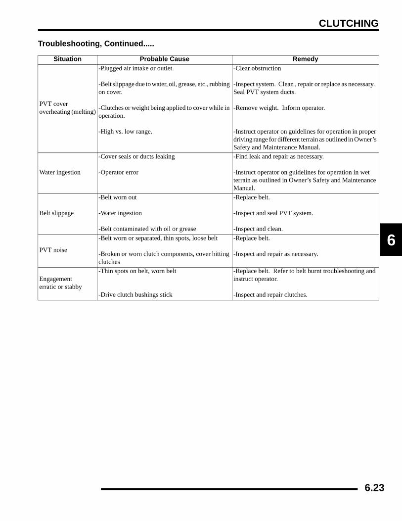
CLUTCHING
6
Troubleshooting, Continued.....
Situation Probable Cause Remedy
PVT cover overheating (melting)
-Plugged air intake or outlet.
-Belt slippage due to water, oil, grease, etc., rubbing on cover.
-Clutches or weight being applied to cover while in operation.
-High vs. low range.
-Clear obstruction
-Inspect system. Clean , repair or replace as necessary. Seal PVT system ducts.
-Remove weight. Inform operator.
-Instruct operator on guidelines for operation in proper driving range for different terrain as outlined in Owner’s Safety and Maintenance Manual.
Water ingestion
-Cover seals or ducts leaking
-Operator error
-Find leak and repair as necessary.
-Instruct operator on guidelines for operation in wet terrain as outlined in Owner’s Safety and Maintenance Manual.
Belt slippage
-Belt worn out
-Water ingestion
-Belt contaminated with oil or grease
-Replace belt.
-Inspect and seal PVT system.
-Inspect and clean.
PVT noise
-Belt worn or separated, thin spots, loose belt
-Broken or worn clutch components, cover hitting clutches
-Replace belt.
-Inspect and repair as necessary.
Engagementerratic or stabby
-Thin spots on belt, worn belt
-Drive clutch bushings stick
-Replace belt. Refer to belt burnt troubleshooting and instruct operator.
-Inspect and repair clutches.
6.23
FINAL DRIVE
CHAPTER 7FINAL DRIVE
7
SPECIAL TOOLS . . . . . . . . . . . . . . . . . . . . . . . . . . . . . . . . . . . . . . . . . . . . . . . . . . . . . . . 7.3TORQUE SPECIFICATIONS. . . . . . . . . . . . . . . . . . . . . . . . . . . . . . . . . . . . . . . . . . . . . . . 7.3
WHEEL, HUB, AND SPINDLE TORQUE TABLE. . . . . . . . . . . . . . . . . . . . . . . . . . . . . . . 7.3FRONT HUB . . . . . . . . . . . . . . . . . . . . . . . . . . . . . . . . . . . . . . . . . . . . . . . . . . . . . . . . . . . 7.3
HUB REMOVAL / INSPECTION. . . . . . . . . . . . . . . . . . . . . . . . . . . . . . . . . . . . . . . . . . . . 7.3HUBSTRUT BEARING REPLACEMENT . . . . . . . . . . . . . . . . . . . . . . . . . . . . . . . . . . . . . 7.4HUB INSTALLATION . . . . . . . . . . . . . . . . . . . . . . . . . . . . . . . . . . . . . . . . . . . . . . . . . . . . 7.5FRONT HUB EXPLODED VIEW . . . . . . . . . . . . . . . . . . . . . . . . . . . . . . . . . . . . . . . . . . . 7.6
DRIVE SHAFT / PROPSHAFT . . . . . . . . . . . . . . . . . . . . . . . . . . . . . . . . . . . . . . . . . . . . . 7.7EXPLODED VIEW . . . . . . . . . . . . . . . . . . . . . . . . . . . . . . . . . . . . . . . . . . . . . . . . . . . . . . 7.7
DRIVESHAFT / CV JOINT HANDLING TIPS . . . . . . . . . . . . . . . . . . . . . . . . . . . . . . . . . . 7.8FRONT DRIVE SHAFT . . . . . . . . . . . . . . . . . . . . . . . . . . . . . . . . . . . . . . . . . . . . . . . . . . . 7.8
REMOVAL . . . . . . . . . . . . . . . . . . . . . . . . . . . . . . . . . . . . . . . . . . . . . . . . . . . . . . . . . . . . 7.8CV JOINT / BOOT REPLACEMENT . . . . . . . . . . . . . . . . . . . . . . . . . . . . . . . . . . . . . . . . 7.9INSTALLATION . . . . . . . . . . . . . . . . . . . . . . . . . . . . . . . . . . . . . . . . . . . . . . . . . . . . . . . 7.11
FRONT PROPSHAFT REMOVAL. . . . . . . . . . . . . . . . . . . . . . . . . . . . . . . . . . . . . . . . . . 7.11PROPSHAFT U-JOINT SERVICE. . . . . . . . . . . . . . . . . . . . . . . . . . . . . . . . . . . . . . . . . . 7.12
DISASSEMBLY. . . . . . . . . . . . . . . . . . . . . . . . . . . . . . . . . . . . . . . . . . . . . . . . . . . . . . . . 7.12ASSEMBLY . . . . . . . . . . . . . . . . . . . . . . . . . . . . . . . . . . . . . . . . . . . . . . . . . . . . . . . . . . 7.13
FRONT GEARCASE CENTRALIZED HILLIARD . . . . . . . . . . . . . . . . . . . . . . . . . . . . . . 7.14AWD OPERATION . . . . . . . . . . . . . . . . . . . . . . . . . . . . . . . . . . . . . . . . . . . . . . . . . . . . . 7.14CENTRALIZED HILLIARD EXPLODED VIEW. . . . . . . . . . . . . . . . . . . . . . . . . . . . . . . . 7.15AWD DIAGNOSIS. . . . . . . . . . . . . . . . . . . . . . . . . . . . . . . . . . . . . . . . . . . . . . . . . . . . . . 7.16GEARCASE REMOVAL . . . . . . . . . . . . . . . . . . . . . . . . . . . . . . . . . . . . . . . . . . . . . . . . . 7.17GEARCASE DISASSEMBLY / INSPECTION. . . . . . . . . . . . . . . . . . . . . . . . . . . . . . . . . 7.18GEARCASE REASSEMBLY / INSPECTION . . . . . . . . . . . . . . . . . . . . . . . . . . . . . . . . . 7.20BACKLASH PAD (THRUST PAD) ADJUSTMENT. . . . . . . . . . . . . . . . . . . . . . . . . . . . . 7.22GEARCASE INSTALLATION . . . . . . . . . . . . . . . . . . . . . . . . . . . . . . . . . . . . . . . . . . . . . 7.23
MID DRIVE HUB / BEARING CARRIER (6X6) . . . . . . . . . . . . . . . . . . . . . . . . . . . . . . . . 7.23REMOVAL . . . . . . . . . . . . . . . . . . . . . . . . . . . . . . . . . . . . . . . . . . . . . . . . . . . . . . . . . . . 7.23HUB DISASSEMBLY . . . . . . . . . . . . . . . . . . . . . . . . . . . . . . . . . . . . . . . . . . . . . . . . . . . 7.24HUB ASSEMBLY . . . . . . . . . . . . . . . . . . . . . . . . . . . . . . . . . . . . . . . . . . . . . . . . . . . . . . 7.24HUB INSTALLATION . . . . . . . . . . . . . . . . . . . . . . . . . . . . . . . . . . . . . . . . . . . . . . . . . . . 7.25MID DRIVE EXPLODED VIEW. . . . . . . . . . . . . . . . . . . . . . . . . . . . . . . . . . . . . . . . . . . . 7.26
MID DRIVE SHAFT (6X6) . . . . . . . . . . . . . . . . . . . . . . . . . . . . . . . . . . . . . . . . . . . . . . . . 7.27REMOVAL . . . . . . . . . . . . . . . . . . . . . . . . . . . . . . . . . . . . . . . . . . . . . . . . . . . . . . . . . . . 7.27DISASSEMBLY / ASSEMBLY . . . . . . . . . . . . . . . . . . . . . . . . . . . . . . . . . . . . . . . . . . . . 7.27INSTALLATION . . . . . . . . . . . . . . . . . . . . . . . . . . . . . . . . . . . . . . . . . . . . . . . . . . . . . . . 7.27
MID PROP SHAFT (6X6). . . . . . . . . . . . . . . . . . . . . . . . . . . . . . . . . . . . . . . . . . . . . . . . . 7.28REMOVAL . . . . . . . . . . . . . . . . . . . . . . . . . . . . . . . . . . . . . . . . . . . . . . . . . . . . . . . . . . . 7.28
MID DRIVE GEARCASE (6X6) . . . . . . . . . . . . . . . . . . . . . . . . . . . . . . . . . . . . . . . . . . . . 7.28GEARCASE REMOVAL . . . . . . . . . . . . . . . . . . . . . . . . . . . . . . . . . . . . . . . . . . . . . . . . . 7.28GEARCASE DISASSEMBLY . . . . . . . . . . . . . . . . . . . . . . . . . . . . . . . . . . . . . . . . . . . . . 7.29GEARCASE ASSEMBLY . . . . . . . . . . . . . . . . . . . . . . . . . . . . . . . . . . . . . . . . . . . . . . . . 7.32GEARCASE INSTALLATION . . . . . . . . . . . . . . . . . . . . . . . . . . . . . . . . . . . . . . . . . . . . . 7.34MID GEARCASE EXPLODED . . . . . . . . . . . . . . . . . . . . . . . . . . . . . . . . . . . . . . . . . . . . 7.35
REAR DRIVE (4X4) . . . . . . . . . . . . . . . . . . . . . . . . . . . . . . . . . . . . . . . . . . . . . . . . . . . . . 7.36EXPLODED VIEW . . . . . . . . . . . . . . . . . . . . . . . . . . . . . . . . . . . . . . . . . . . . . . . . . . . . . 7.36
7.1
FINAL DRIVE
REAR HUB / BEARING CARRIER (4X4) . . . . . . . . . . . . . . . . . . . . . . . . . . . . . . . . . . . . 7.36HUB INSPECTION . . . . . . . . . . . . . . . . . . . . . . . . . . . . . . . . . . . . . . . . . . . . . . . . . . . . . 7.36HUB REMOVAL . . . . . . . . . . . . . . . . . . . . . . . . . . . . . . . . . . . . . . . . . . . . . . . . . . . . . . . 7.36HUB DISASSEMBLY . . . . . . . . . . . . . . . . . . . . . . . . . . . . . . . . . . . . . . . . . . . . . . . . . . . 7.37HUB ASSEMBLY . . . . . . . . . . . . . . . . . . . . . . . . . . . . . . . . . . . . . . . . . . . . . . . . . . . . . . 7.38HUB INSTALLATION . . . . . . . . . . . . . . . . . . . . . . . . . . . . . . . . . . . . . . . . . . . . . . . . . . . 7.38
REAR DRIVE SHAFT (4X4) . . . . . . . . . . . . . . . . . . . . . . . . . . . . . . . . . . . . . . . . . . . . . . 7.39REMOVAL . . . . . . . . . . . . . . . . . . . . . . . . . . . . . . . . . . . . . . . . . . . . . . . . . . . . . . . . . . . 7.39CV JOINT / BOOT REPLACEMENT . . . . . . . . . . . . . . . . . . . . . . . . . . . . . . . . . . . . . . . 7.40INSTALLATION . . . . . . . . . . . . . . . . . . . . . . . . . . . . . . . . . . . . . . . . . . . . . . . . . . . . . . . 7.42
REAR PROPSHAFT (4X4) . . . . . . . . . . . . . . . . . . . . . . . . . . . . . . . . . . . . . . . . . . . . . . . 7.43REMOVAL . . . . . . . . . . . . . . . . . . . . . . . . . . . . . . . . . . . . . . . . . . . . . . . . . . . . . . . . . . . 7.43INSTALLATION . . . . . . . . . . . . . . . . . . . . . . . . . . . . . . . . . . . . . . . . . . . . . . . . . . . . . . . 7.43
REAR GEARCASE (4X4) . . . . . . . . . . . . . . . . . . . . . . . . . . . . . . . . . . . . . . . . . . . . . . . . 7.44GENERAL OPERATION . . . . . . . . . . . . . . . . . . . . . . . . . . . . . . . . . . . . . . . . . . . . . . . . 7.44OPERATION MODES . . . . . . . . . . . . . . . . . . . . . . . . . . . . . . . . . . . . . . . . . . . . . . . . . . 7.45DIFFERENTIAL REMOVAL . . . . . . . . . . . . . . . . . . . . . . . . . . . . . . . . . . . . . . . . . . . . . . 7.46DIFFERENTIAL DISASSEMBLY . . . . . . . . . . . . . . . . . . . . . . . . . . . . . . . . . . . . . . . . . . 7.46DIFFERENTIAL ASSEMBLY . . . . . . . . . . . . . . . . . . . . . . . . . . . . . . . . . . . . . . . . . . . . . 7.49DIFFERENTIAL INSTALLATION . . . . . . . . . . . . . . . . . . . . . . . . . . . . . . . . . . . . . . . . . . 7.51DIFFERENTIAL EXPLODED VIEW . . . . . . . . . . . . . . . . . . . . . . . . . . . . . . . . . . . . . . . . 7.52
REAR AXLE / GEARCASE SERVICE (6X6) . . . . . . . . . . . . . . . . . . . . . . . . . . . . . . . . . . 7.53REAR AXLE REMOVAL. . . . . . . . . . . . . . . . . . . . . . . . . . . . . . . . . . . . . . . . . . . . . . . . . 7.53AXLE TUBE REMOVAL . . . . . . . . . . . . . . . . . . . . . . . . . . . . . . . . . . . . . . . . . . . . . . . . . 7.54AXLE TUBE BEARING REPLACEMENT. . . . . . . . . . . . . . . . . . . . . . . . . . . . . . . . . . . . 7.55GEARCASE DISASSEMBLY / INSPECTION . . . . . . . . . . . . . . . . . . . . . . . . . . . . . . . . 7.55GEARCASE ASSEMBLY . . . . . . . . . . . . . . . . . . . . . . . . . . . . . . . . . . . . . . . . . . . . . . . . 7.56GEARCASE / AXLE INSTALLATION. . . . . . . . . . . . . . . . . . . . . . . . . . . . . . . . . . . . . . . 7.57GEARCASE EXPLODED VIEW. . . . . . . . . . . . . . . . . . . . . . . . . . . . . . . . . . . . . . . . . . . 7.60
7.2
FINAL DRIVE
7
SPECIAL TOOLS
TORQUE SPECIFICATIONSWheel, Hub, and Spindle Torque Table
FRONT HUBHub Removal / Inspection1. Elevate front end and safely support machine under
footrest / frame area.
2. Check bearings for side play by grasping the tire / wheelfirmly and checking for movement. Grasp the top andbottom of the tire. The tire should rotate smoothly withoutbinding or rough spots.
3. Remove wheel nuts, washers, and wheel.
4. Remove the two brake caliper attaching bolts.CAUTION: Do not hang the caliper by the brake line. Usewire to hang the caliper to prevent possible damage to thebrake line.
PART NUMBER TOOL DESCRIPTION
2872608 Roller Pin Removal Tool
8700226 CV Boot Clamp Pliers
ITEM NUT TYPE SPECIFICATION
Aluminum Wheels (Cast)
Lug Nut (1) 90 ft. lbs. (122 Nm)
Steel Wheels (Black / Camo)
Flange Nut (2) 35 ft. lbs. (47 Nm)
Front Spindle Nut - 70 ft. lbs. (95 Nm)
Rear & Middle Hub Retaining Nut
- 110 ft. lbs. (150 Nm)
Steel Wheel(Standard Models)35 ft. lbs. (47 Nm)
Aluminum Wheel(LE Models)
90 ft. lbs. (122 Nm)
#1 #2
CAUTION
Serious injury may result if machine tips or falls. Be sure machine is secure before beginning this service procedure. Wear eye protection when
removing bearings and seals.
7.3
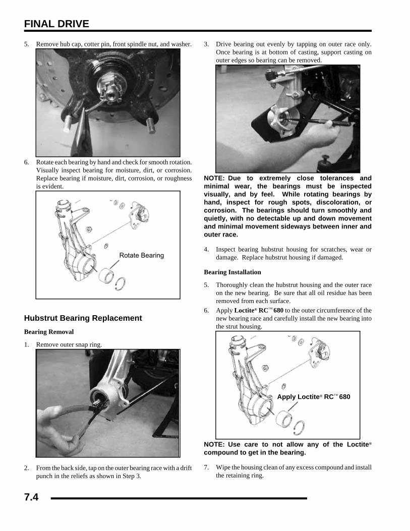
FINAL DRIVE
5. Remove hub cap, cotter pin, front spindle nut, and washer.
6. Rotate each bearing by hand and check for smooth rotation.Visually inspect bearing for moisture, dirt, or corrosion.Replace bearing if moisture, dirt, corrosion, or roughnessis evident.
Hubstrut Bearing ReplacementBearing Removal
1. Remove outer snap ring.
2. From the back side, tap on the outer bearing race with a driftpunch in the reliefs as shown in Step 3.
3. Drive bearing out evenly by tapping on outer race only.Once bearing is at bottom of casting, support casting onouter edges so bearing can be removed.
NOTE: Due to extremely close tolerances andminimal wear, the bearings must be inspectedvisually, and by feel. While rotating bearings byhand, inspect for rough spots, discoloration, orcorrosion. The bearings should turn smoothly andquietly, with no detectable up and down movementand minimal movement sideways between inner andouter race.
4. Inspect bearing hubstrut housing for scratches, wear ordamage. Replace hubstrut housing if damaged.
Bearing Installation
5. Thoroughly clean the hubstrut housing and the outer raceon the new bearing. Be sure that all oil residue has beenremoved from each surface.
6. Apply Loctite® RC™ 680 to the outer circumference of thenew bearing race and carefully install the new bearing intothe strut housing.
NOTE: Use care to not allow any of the Loctite®
compound to get in the bearing.
7. Wipe the housing clean of any excess compound and installthe retaining ring.
Rotate Bearing
Apply Loctite® RC™ 680
7.4
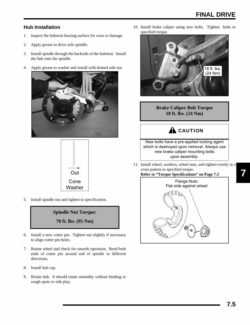
FINAL DRIVE
7
Hub Installation1. Inspect the hubstrut bearing surface for wear or damage.
2. Apply grease to drive axle spindle.
3. Install spindle through the backside of the hubstrut. Installthe hub onto the spindle.
4. Apply grease to washer and install with domed side out.
5. Install spindle nut and tighten to specification.
6. Install a new cotter pin. Tighten nut slightly if necessaryto align cotter pin holes.
7. Rotate wheel and check for smooth operation. Bend bothends of cotter pin around end of spindle in differentdirections.
8. Install hub cap.
9. Rotate hub. It should rotate smoothly without binding orrough spots or side play.
10. Install brake caliper using new bolts. Tighten bolts tospecified torque.
11. Install wheel, washers, wheel nuts, and tighten evenly in across pattern to specified torque.Refer to “Torque Specifications” on Page 7.3
Spindle Nut Torque:
70 ft. lbs. (95 Nm)
Out
ConeWasher
Brake Caliper Bolt Torque18 ft. lbs. (24 Nm)
CAUTION
New bolts have a pre-applied locking agent which is destroyed upon removal. Always use
new brake caliper mounting bolts upon assembly.
18 ft. lbs.(24 Nm)
Flange Nuts:Flat side against wheel
7.5
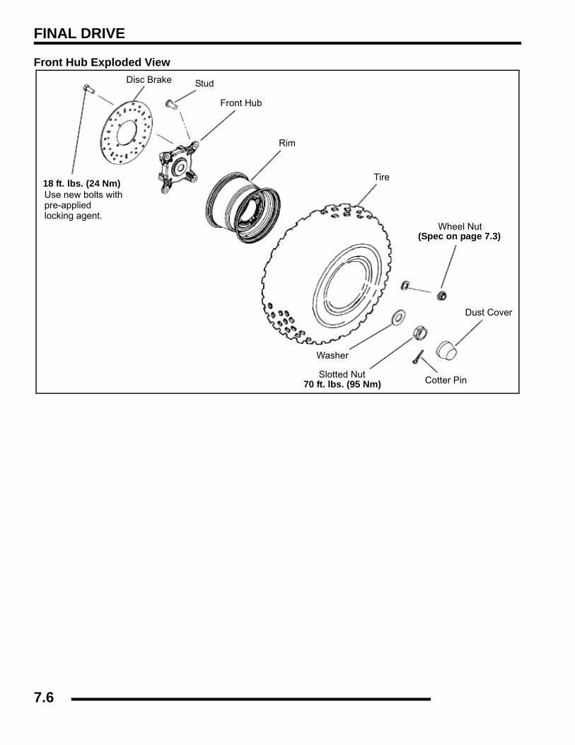
FINAL DRIVE
Front Hub Exploded View
18 ft. lbs. (24 Nm)Use new bolts withpre-appliedlocking agent.
Disc Brake Stud
Front Hub
Rim
Tire
Wheel Nut
Dust Cover
Cotter Pin
Washer
Slotted Nut70 ft. lbs. (95 Nm)
(Spec on page 7.3)
7.6

FINAL DRIVE
7
DRIVE SHAFT / PROPSHAFTExploded View
RANGER Front Driveshaft
CV Joint30g Grease Packet
Inner ClampsPlunging Joint
Circlip
Clamp ClampBoots
30g Grease Packet
RANGER Front PropshaftJoint Kit
Front Yoke
Shaft
Yoke
Grease Zerk O-ring
RANGER 4X4 & 6X6 Rear Propshaft
Cross & Bearing Kit
6X64X4
Spring PinO-ring
Cross & Bearing Kit
Grease Zerk
O-ring
Cross & Bearing Kit
Spring Pin
7.7
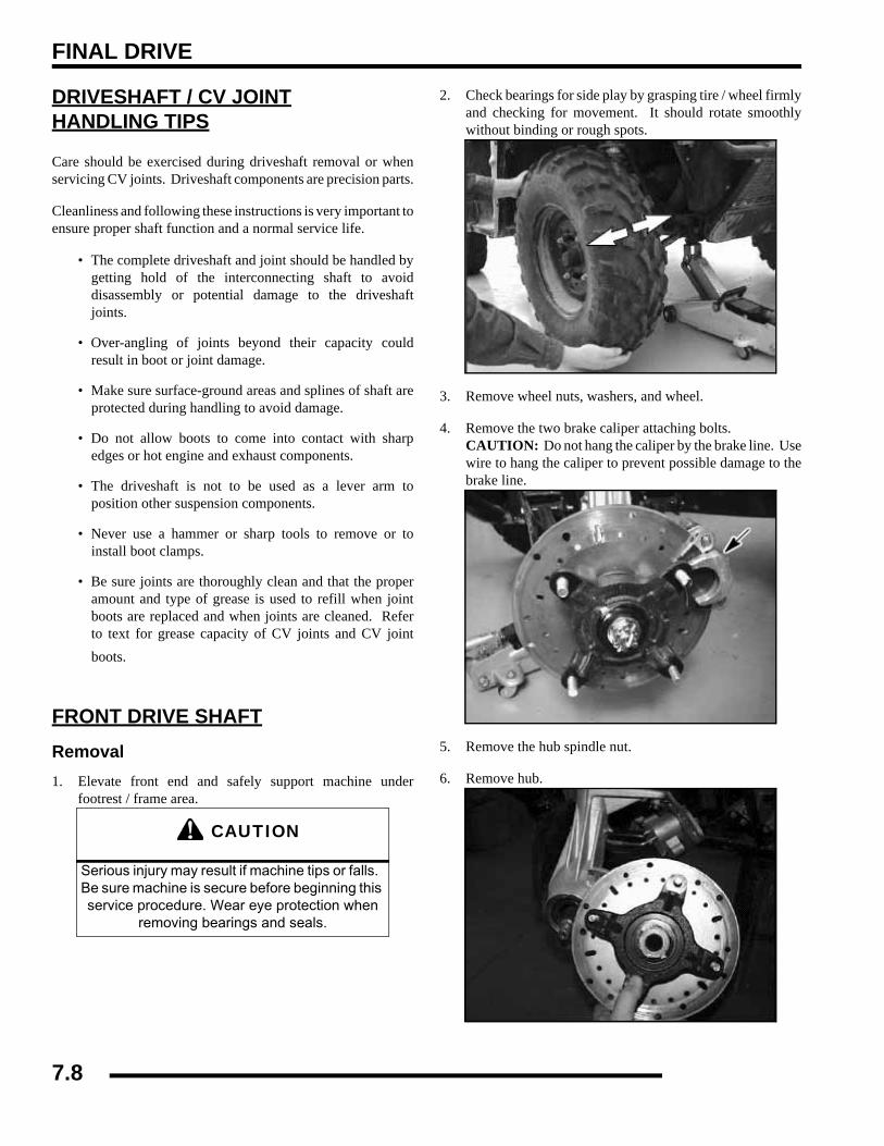
FINAL DRIVE
DRIVESHAFT / CV JOINTHANDLING TIPS
Care should be exercised during driveshaft removal or whenservicing CV joints. Driveshaft components are precision parts.
Cleanliness and following these instructions is very important toensure proper shaft function and a normal service life.
• The complete driveshaft and joint should be handled bygetting hold of the interconnecting shaft to avoiddisassembly or potential damage to the driveshaftjoints.
• Over-angling of joints beyond their capacity couldresult in boot or joint damage.
• Make sure surface-ground areas and splines of shaft areprotected during handling to avoid damage.
• Do not allow boots to come into contact with sharpedges or hot engine and exhaust components.
• The driveshaft is not to be used as a lever arm toposition other suspension components.
• Never use a hammer or sharp tools to remove or toinstall boot clamps.
• Be sure joints are thoroughly clean and that the properamount and type of grease is used to refill when jointboots are replaced and when joints are cleaned. Referto text for grease capacity of CV joints and CV jointboots.
FRONT DRIVE SHAFTRemoval1. Elevate front end and safely support machine under
footrest / frame area.
2. Check bearings for side play by grasping tire / wheel firmlyand checking for movement. It should rotate smoothlywithout binding or rough spots.
3. Remove wheel nuts, washers, and wheel.
4. Remove the two brake caliper attaching bolts. CAUTION: Do not hang the caliper by the brake line. Usewire to hang the caliper to prevent possible damage to thebrake line.
5. Remove the hub spindle nut.
6. Remove hub.
CAUTION
Serious injury may result if machine tips or falls. Be sure machine is secure before beginning this service procedure. Wear eye protection when
removing bearings and seals.
7.8
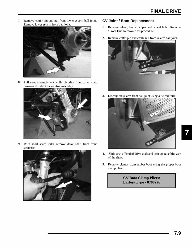
FINAL DRIVE
7
7. Remove cotter pin and nut from lower A-arm ball joint.Remove lower A-arm from ball joint.
8. Pull strut assembly out while pivoting front drive shaftdownward until it clears strut assembly.
9. With short sharp jerks, remove drive shaft from frontgearcase.
CV Joint / Boot Replacement1. Remove wheel, brake caliper and wheel hub. Refer to
“Front Hub Removal” for procedure.
2. Remove cotter pin and castle nut from A-arm ball joint.
3. Disconnect A-arm from ball joint using a tie rod fork.
4. Slide strut off end of drive shaft and tie it up out of the wayof the shaft.
5. Remove clamps from rubber boot using the proper bootclamp pliers.
CV Boot Clamp Pliers:Earless Type - 8700226
7.9
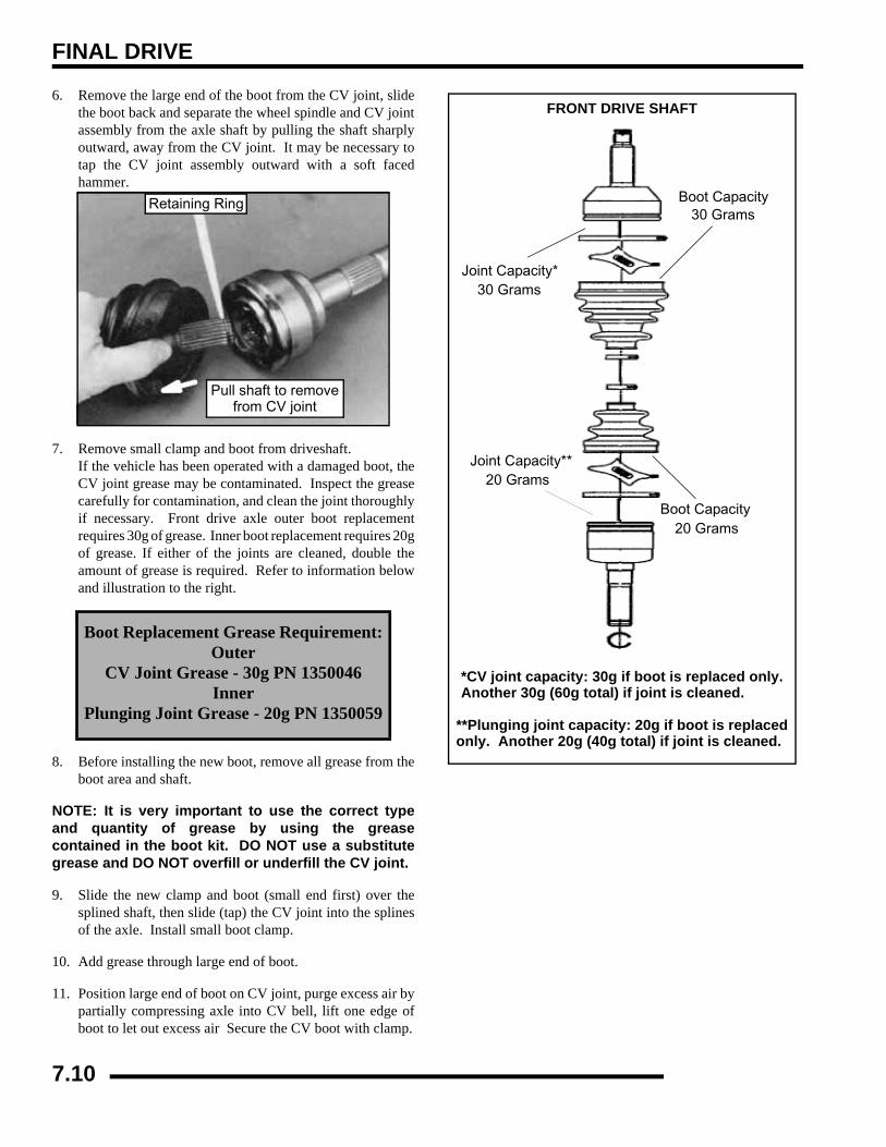
FINAL DRIVE
6. Remove the large end of the boot from the CV joint, slidethe boot back and separate the wheel spindle and CV jointassembly from the axle shaft by pulling the shaft sharplyoutward, away from the CV joint. It may be necessary totap the CV joint assembly outward with a soft facedhammer.
7. Remove small clamp and boot from driveshaft.If the vehicle has been operated with a damaged boot, theCV joint grease may be contaminated. Inspect the greasecarefully for contamination, and clean the joint thoroughlyif necessary. Front drive axle outer boot replacementrequires 30g of grease. Inner boot replacement requires 20gof grease. If either of the joints are cleaned, double theamount of grease is required. Refer to information belowand illustration to the right.
8. Before installing the new boot, remove all grease from theboot area and shaft.
NOTE: It is very important to use the correct typeand quantity of grease by using the greasecontained in the boot kit. DO NOT use a substitutegrease and DO NOT overfill or underfill the CV joint.
9. Slide the new clamp and boot (small end first) over thesplined shaft, then slide (tap) the CV joint into the splinesof the axle. Install small boot clamp.
10. Add grease through large end of boot.
11. Position large end of boot on CV joint, purge excess air bypartially compressing axle into CV bell, lift one edge ofboot to let out excess air Secure the CV boot with clamp.
Boot Replacement Grease Requirement:Outer
CV Joint Grease - 30g PN 1350046Inner
Plunging Joint Grease - 20g PN 1350059
Retaining Ring
Pull shaft to removefrom CV joint
FRONT DRIVE SHAFT
Joint Capacity*30 Grams
Boot Capacity20 Grams
*CV joint capacity: 30g if boot is replaced only.
Boot Capacity30 Grams
Joint Capacity**20 Grams
Another 30g (60g total) if joint is cleaned.
only. Another 20g (40g total) if joint is cleaned.**Plunging joint capacity: 20g if boot is replaced
7.10
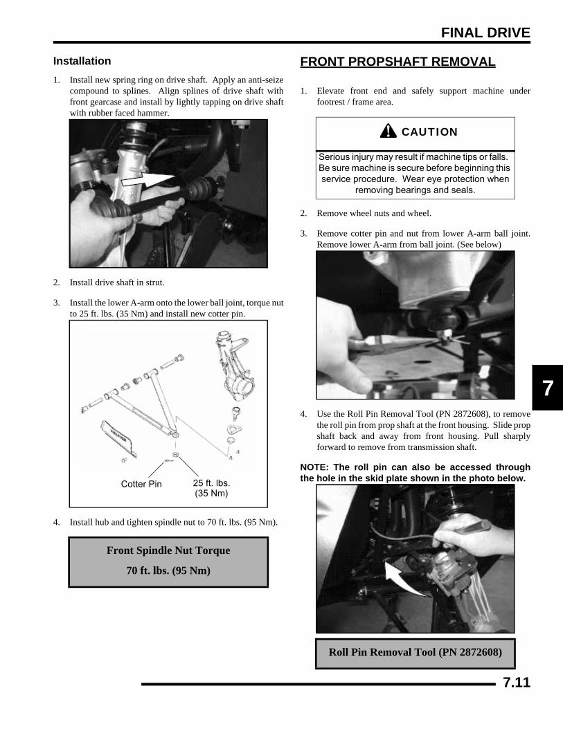
FINAL DRIVE
7
Installation1. Install new spring ring on drive shaft. Apply an anti-seize
compound to splines. Align splines of drive shaft withfront gearcase and install by lightly tapping on drive shaftwith rubber faced hammer.
2. Install drive shaft in strut.
3. Install the lower A-arm onto the lower ball joint, torque nutto 25 ft. lbs. (35 Nm) and install new cotter pin.
4. Install hub and tighten spindle nut to 70 ft. lbs. (95 Nm).
FRONT PROPSHAFT REMOVAL
1. Elevate front end and safely support machine underfootrest / frame area.
2. Remove wheel nuts and wheel.
3. Remove cotter pin and nut from lower A-arm ball joint.Remove lower A-arm from ball joint. (See below)
4. Use the Roll Pin Removal Tool (PN 2872608), to removethe roll pin from prop shaft at the front housing. Slide propshaft back and away from front housing. Pull sharplyforward to remove from transmission shaft.
NOTE: The roll pin can also be accessed throughthe hole in the skid plate shown in the photo below.
Front Spindle Nut Torque
70 ft. lbs. (95 Nm)
25 ft. lbs.(35 Nm)
Cotter Pin
CAUTION
Serious injury may result if machine tips or falls. Be sure machine is secure before beginning this service procedure. Wear eye protection when
removing bearings and seals.
Roll Pin Removal Tool (PN 2872608)
7.11
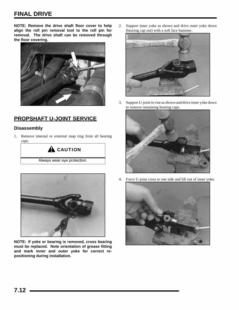
FINAL DRIVE
NOTE: Remove the drive shaft floor cover to helpalign the roll pin removal tool to the roll pin forremoval. The drive shaft can be removed throughthe floor covering.
PROPSHAFT U-JOINT SERVICEDisassembly1. Remove internal or external snap ring from all bearing
caps.
NOTE: If yoke or bearing is removed, cross bearingmust be replaced. Note orientation of grease fittingand mark inner and outer yoke for correct re-positioning during installation.
2. Support inner yoke as shown and drive outer yoke down(bearing cap out) with a soft face hammer.
3. Support U-joint in vise as shown and drive inner yoke downto remove remaining bearing caps.
4. Force U-joint cross to one side and lift out of inner yoke.
CAUTION
Always wear eye protection.
7.12
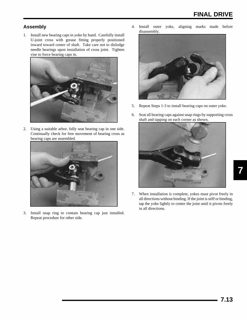
FINAL DRIVE
7
Assembly1. Install new bearing caps in yoke by hand. Carefully install
U-joint cross with grease fitting properly positionedinward toward center of shaft. Take care not to dislodgeneedle bearings upon installation of cross joint. Tightenvise to force bearing caps in.
2. Using a suitable arbor, fully seat bearing cap in one side.Continually check for free movement of bearing cross asbearing caps are assembled.
3. Install snap ring to contain bearing cap just installed.Repeat procedure for other side.
4. Install outer yoke, aligning marks made beforedisassembly.
5. Repeat Steps 1-3 to install bearing caps on outer yoke.
6. Seat all bearing caps against snap rings by supporting crossshaft and tapping on each corner as shown.
7. When installation is complete, yokes must pivot freely inall directions without binding. If the joint is stiff or binding,tap the yoke lightly to center the joint until it pivots freelyin all directions.
7.13

FINAL DRIVE
FRONT GEARCASECENTRALIZED HILLIARD
AWD OperationEngaging Front Gearcase: The AWD switch may be turned onor off while the vehicle is moving. Initially, the vehicle’selectronic system will not enable the AWD until the engine RPMis below 3100. Once enabled, the AWD remains while the frontgearcase is moving, it will not disengage until the rear wheelsregain traction.
Engage the AWD switch before getting into conditions wherethe front wheel drive may be needed. If the rear wheels arespinning , release the throttle before switching to AWD.
Normal Operation: With the AWD switch off the vehicledrives only the rear wheels (2 wheel drive). When the AWDswitch is activated it engages the Hilliard, locking both frontaxles into All Wheel Drive.
4X4 Engagement: When the AWD switch is activated, a 12VDC current charges the central coil which creates a magneticfield. This magnetic field attracts an armature plate keyed to aroller cage that contains 14 rollers and roller cam. The differencein rpm by input shaft and front axles the forces the rollers up theexternal cam. The rollers engage themselves to the output hubsthat link both front axles, resulting in True All Wheel Drive.
Roller Cage and Roller’s Rotate Inward and Grip the Output hubfor AWD Engagement
Disengagement: As the front and rear wheels gain traction,rotating very close to the same speed, the front wheels“overdrive” the output hubs and the rollers are forced outward,disengaging the AWD. The vehicle is now back to rear wheeldrive until the next loss of traction.
CAUTION
Switching to AWD while the rear wheels are spinning may cause severe drive shaft and
gearcase damage. Always switch to AWD while the rear wheels have traction or are at rest.
CoilArmature
Plate
Roller Cage
Cover
Output Hub
Armature plate design maydiffer from what is shown
CAUTION
If the rear wheels are spinning, release the throttle before turning the AWD switch on.If AWD is engaged while the wheels are spinning, severe drive shaft and clutch
damage could result.
Output Hub Rollers
Roller Cage& Bearings
7.14
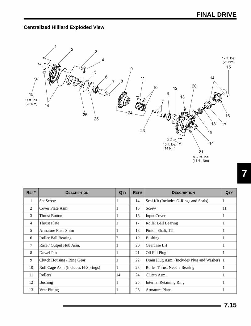
FINAL DRIVE
7
Centralized Hilliard Exploded View
REF# DESCRIPTION QTY REF# DESCRIPTION QTY
1 Set Screw 1 14 Seal Kit (Includes O-Rings and Seals) 1
2 Cover Plate Asm. 1 15 Screw 11
3 Thrust Button 1 16 Input Cover 1
4 Thrust Plate 1 17 Roller Ball Bearing 1
5 Armature Plate Shim 1 18 Pinion Shaft, 11T 1
6 Roller Ball Bearing 2 19 Bushing 1
7 Race / Output Hub Asm. 1 20 Gearcase LH 1
8 Dowel Pin 1 21 Oil Fill Plug 1
9 Clutch Housing / Ring Gear 1 22 Drain Plug Asm. (Includes Plug and Washer) 1
10 Roll Cage Asm (Includes H-Springs) 1 23 Roller Thrust Needle Bearing 1
11 Rollers 14 24 Clutch Asm. 1
12 Bushing 1 25 Internal Retaining Ring 1
13 Vent Fitting 1 26 Armature Plate 1
12 3
4
56
7 8
9
10
11
12
13
14
15
16
1718
19
20
21
22
23
15
14
14
7
2425
26
6
10 ft. lbs.(14 Nm)
8-30 ft. lbs.(11-41 Nm)
17 ft. lbs.(23 Nm)
17 ft. lbs.(23 Nm)
7.15
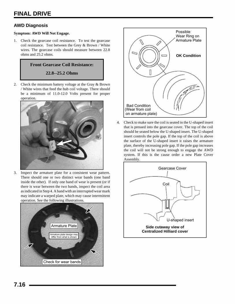
FINAL DRIVE
AWD DiagnosisSymptom: AWD Will Not Engage.
1. Check the gearcase coil resistance. To test the gearcasecoil resistance. Test between the Grey & Brown / Whitewires. The gearcase coils should measure between 22.8ohms and 25.2 ohms.
2. Check the minimum battery voltage at the Gray & Brown/ White wires that feed the hub coil voltage. There shouldbe a minimum of 11.0-12.0 Volts present for properoperation.
3. Inspect the armature plate for a consistent wear pattern.There should one or two distinct wear bands (one bandinside the other). If only one band of wear is present (or ifthere is wear between the two bands, inspect the coil areaas indicated in Step 4. A band with an interrupted wear markmay indicate a warped plate, which may cause intermittentoperation. See the following illustrations.
4. Check to make sure the coil is seated in the U-shaped insertthat is pressed into the gearcase cover. The top of the coilshould be seated below the U-shaped insert. The U-shapedinsert controls the pole gap. If the top of the coil is abovethe surface of the U-shaped insert it raises the armatureplate, thereby increasing pole gap. If the pole gap increasesthe coil will not be strong enough to engage the AWDsystem. If this is the cause order a new Plate CoverAssembly.
Front Gearcase Coil Resistance:
22.8--25.2 Ohms
Check for wear bands
Armature Plate
Armature plate design maydiffer from what is shown
Possible Wear Ring onArmature Plate
OK Condition
Bad Condition(Wear from coilon armature plate)
Gearcase Cover
Coil
U-shaped insert
Side cutaway view ofCentralized Hilliard cover
7.16
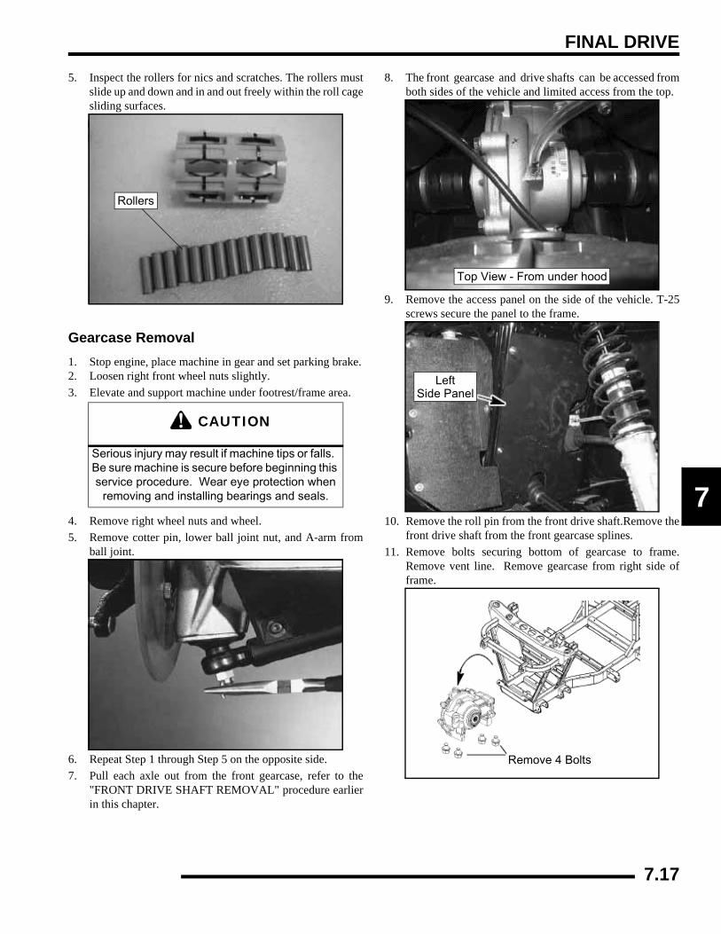
FINAL DRIVE
7
5. Inspect the rollers for nics and scratches. The rollers mustslide up and down and in and out freely within the roll cagesliding surfaces.
Gearcase Removal1. Stop engine, place machine in gear and set parking brake.2. Loosen right front wheel nuts slightly.3. Elevate and support machine under footrest/frame area.
4. Remove right wheel nuts and wheel.5. Remove cotter pin, lower ball joint nut, and A-arm from
ball joint.
6. Repeat Step 1 through Step 5 on the opposite side.7. Pull each axle out from the front gearcase, refer to the
"FRONT DRIVE SHAFT REMOVAL" procedure earlierin this chapter.
8. The front gearcase and drive shafts can be accessed fromboth sides of the vehicle and limited access from the top.
9. Remove the access panel on the side of the vehicle. T-25screws secure the panel to the frame.
10. Remove the roll pin from the front drive shaft.Remove thefront drive shaft from the front gearcase splines.
11. Remove bolts securing bottom of gearcase to frame.Remove vent line. Remove gearcase from right side offrame.
CAUTION
Serious injury may result if machine tips or falls. Be sure machine is secure before beginning this service procedure. Wear eye protection when
removing and installing bearings and seals.
Rollers
Top View - From under hood
LeftSide Panel
Remove 4 Bolts
7.17

FINAL DRIVE
Gearcase Disassembly / Inspection1. Drain and properly dispose of used oil. Remove any metal
particles from the drain plug magnet.2. Remove bolts and output shaft cover.
3. Check the gearcase coil resistance. The resistance valueshould meet the specifications listed below.
NOTE: To test the gearcase coils resistance, use thecoil harness. The gearcase coils should measurebetween 22.8 ohms and 25.2 ohms.
4. Remove output shaft assembly
NOTE: Be careful not to misplace the thrust bearinglocated between the two output shafts.
5. Clean all parts and inspect spacers for wear. Inspect ringgear for chipped, broken, or missing teeth.
6. Remove the roll cage assembly, rollers, and H-springs.
7. Thoroughly clean all parts. Inspect the rollers (A) for nicksand scratches. The rollers must slide up and down freelywithin the roller cage surfaces (B).
8. Inspect the ring gear (C) for consistent wear patterns. Thesurfaces should be free of nicks and scratches.
9. Inspect roll cage (B) sliding surface. This surface must beclean and free of nicks, burrs or scratches. Remove andinspect the H-springs.
C
A
B
BH-Spring
7.18
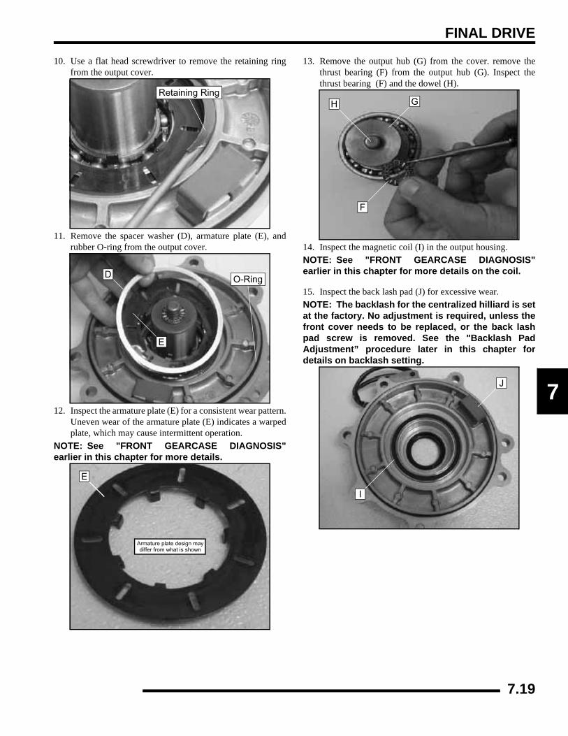
FINAL DRIVE
7
10. Use a flat head screwdriver to remove the retaining ringfrom the output cover.
11. Remove the spacer washer (D), armature plate (E), andrubber O-ring from the output cover.
12. Inspect the armature plate (E) for a consistent wear pattern.Uneven wear of the armature plate (E) indicates a warpedplate, which may cause intermittent operation.
NOTE: See "FRONT GEARCASE DIAGNOSIS"earlier in this chapter for more details.
13. Remove the output hub (G) from the cover. remove thethrust bearing (F) from the output hub (G). Inspect thethrust bearing (F) and the dowel (H).
14. Inspect the magnetic coil (I) in the output housing.NOTE: See "FRONT GEARCASE DIAGNOSIS"earlier in this chapter for more details on the coil.
15. Inspect the back lash pad (J) for excessive wear.NOTE: The backlash for the centralized hilliard is setat the factory. No adjustment is required, unless thefront cover needs to be replaced, or the back lashpad screw is removed. See the "Backlash PadAdjustment” procedure later in this chapter fordetails on backlash setting.
Retaining Ring
D
E
O-Ring
E
Armature plate design maydiffer from what is shown
H G
F
I
J
7.19
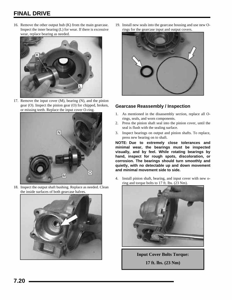
FINAL DRIVE
16. Remove the other output hub (K) from the main gearcase.Inspect the inner bearing (L) for wear. If there is excessivewear, replace bearing as needed.
17. Remove the input cover (M), bearing (N), and the piniongear (O). Inspect the pinion gear (O) for chipped, broken,or missing teeth. Replace the input cover O-ring.
18. Inspect the output shaft bushing. Replace as needed. Cleanthe inside surfaces of both gearcase halves.
19. Install new seals into the gearcase housing and use new O-rings for the gearcase input and output covers.
Gearcase Reassembly / Inspection1. As mentioned in the disassembly section, replace all O-
rings, seals, and worn components.2. Press the pinion shaft seal into the pinion cover, until the
seal is flush with the sealing surface.3. Inspect bearings on output and pinion shafts. To replace,
press new bearing on to shaft.NOTE: Due to extremely close tolerances andminimal wear, the bearings must be inspectedvisually, and by feel. While rotating bearings byhand, inspect for rough spots, discoloration, orcorrosion. The bearings should turn smoothly andquietly, with no detectable up and down movementand minimal movement side to side.
4. Install pinion shaft, bearing, and input cover with new o-ring and torque bolts to 17 ft. lbs. (23 Nm).
K
L
M
N
O
Input Cover Bolts Torque:
17 ft. lbs. (23 Nm)
7.20

FINAL DRIVE
7
5. Install the output hub (A) into the gearcase housing. Theoutput hub should spin freely.
6. Install the other output hub (B) and thrust bearing (C) intothe output cover. Apply a small amount of grease onto thethrust bearing.
7. Install the armature plate (D) and spacer washer (E) into theoutput cover.
NOTE: Be sure backlash plate is in place.
8. Install the retaining ring (F) into the output cover. Be surethe retaining ring is properly seated into the cover.
9. Install the ring gear (G) onto the output hub on the outputcover.
10. Install the rollers and roll cage into the ring gear. Insert therollers as the roll cage is installed.
A
B
C
E
D
Backlash Plate
F
G
7.21
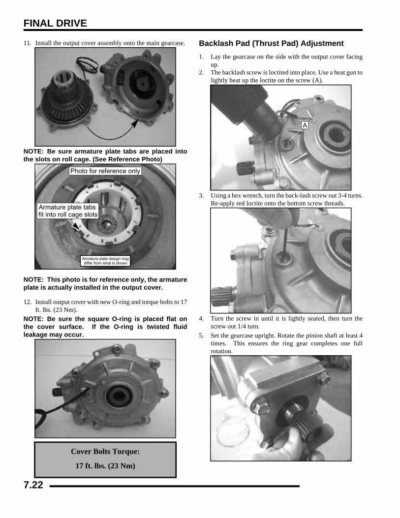
FINAL DRIVE
11. Install the output cover assembly onto the main gearcase.
NOTE: Be sure armature plate tabs are placed intothe slots on roll cage. (See Reference Photo)
NOTE: This photo is for reference only, the armatureplate is actually installed in the output cover.
12. Install output cover with new O-ring and torque bolts to 17ft. lbs. (23 Nm).
NOTE: Be sure the square O-ring is placed flat onthe cover surface. If the O-ring is twisted fluidleakage may occur.
Backlash Pad (Thrust Pad) Adjustment1. Lay the gearcase on the side with the output cover facing
up.2. The backlash screw is loctited into place. Use a heat gun to
lightly heat up the loctite on the screw (A).
3. Using a hex wrench, turn the back-lash screw out 3-4 turns.Re-apply red loctite onto the bottom screw threads.
4. Turn the screw in until it is lightly seated, then turn thescrew out 1/4 turn.
5. Set the gearcase upright. Rotate the pinion shaft at least 4times. This ensures the ring gear completes one fullrotation.
Cover Bolts Torque:
17 ft. lbs. (23 Nm)
Armature plate design maydiffer from what is shown
Photo for reference only
Armature plate tabs fit into roll cage slots
A
7.22
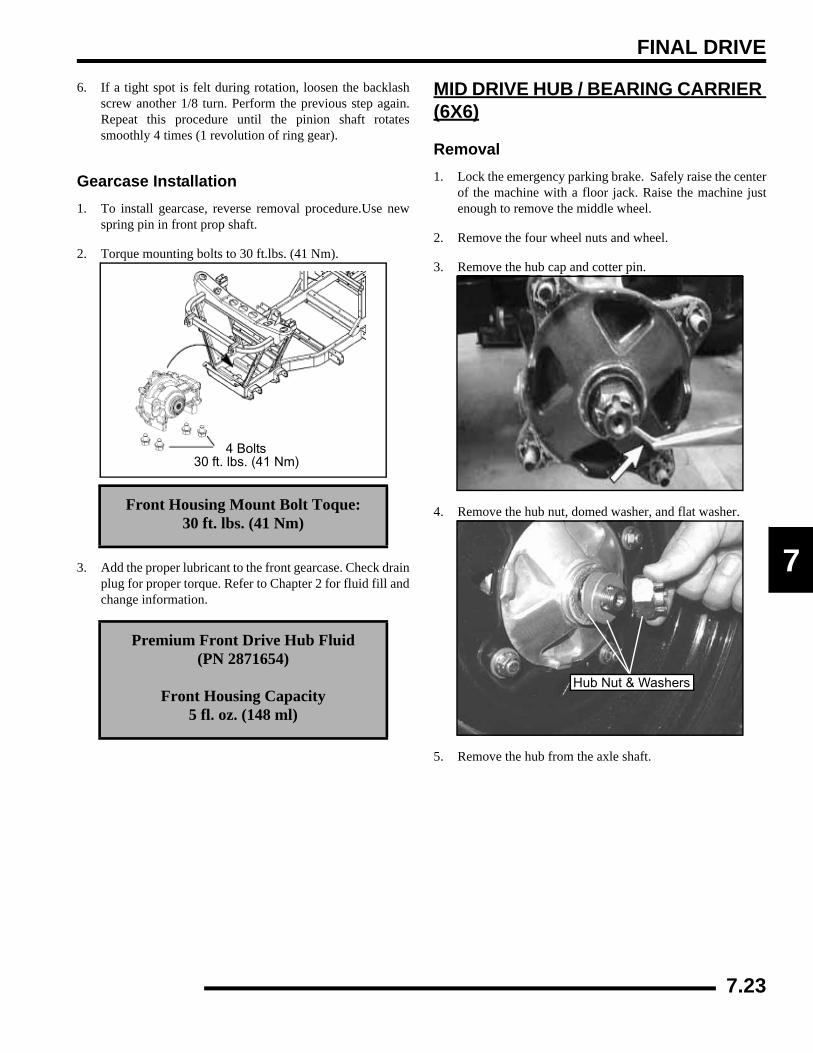
FINAL DRIVE
7
6. If a tight spot is felt during rotation, loosen the backlashscrew another 1/8 turn. Perform the previous step again.Repeat this procedure until the pinion shaft rotatessmoothly 4 times (1 revolution of ring gear).
Gearcase Installation1. To install gearcase, reverse removal procedure.Use new
spring pin in front prop shaft.
2. Torque mounting bolts to 30 ft.lbs. (41 Nm).
3. Add the proper lubricant to the front gearcase. Check drainplug for proper torque. Refer to Chapter 2 for fluid fill andchange information.
MID DRIVE HUB / BEARING CARRIER (6X6)
Removal1. Lock the emergency parking brake. Safely raise the center
of the machine with a floor jack. Raise the machine justenough to remove the middle wheel.
2. Remove the four wheel nuts and wheel.
3. Remove the hub cap and cotter pin.
4. Remove the hub nut, domed washer, and flat washer.
5. Remove the hub from the axle shaft.
Front Housing Mount Bolt Toque: 30 ft. lbs. (41 Nm)
Premium Front Drive Hub Fluid (PN 2871654)
Front Housing Capacity 5 fl. oz. (148 ml)
4 Bolts30 ft. lbs. (41 Nm)
Hub Nut & Washers
7.23
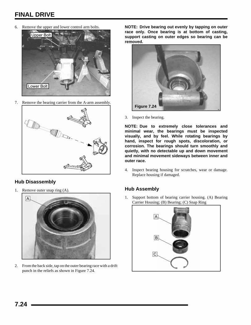
FINAL DRIVE
6. Remove the upper and lower control arm bolts.
7. Remove the bearing carrier from the A-arm assembly.
Hub Disassembly1. Remove outer snap ring (A).
2. From the back side, tap on the outer bearing race with a driftpunch in the reliefs as shown in Figure 7.24.
NOTE: Drive bearing out evenly by tapping on outerrace only. Once bearing is at bottom of casting,support casting on outer edges so bearing can beremoved.
3. Inspect the bearing.
NOTE: Due to extremely close tolerances andminimal wear, the bearings must be inspectedvisually, and by feel. While rotating bearings byhand, inspect for rough spots, discoloration, orcorrosion. The bearings should turn smoothly andquietly, with no detectable up and down movementand minimal movement sideways between inner andouter race.
4. Inspect bearing housing for scratches, wear or damage.Replace housing if damaged.
Hub Assembly1. Support bottom of bearing carrier housing. (A) Bearing
Carrier Housing; (B) Bearing; (C) Snap Ring
Lower Bolt
Upper Bolt
A
Figure 7.24
A
B
C
7.24

FINAL DRIVE
7
2. Start bearing (B) in housing (A).
3. Press bearing into place until outer race bottoms onhousing.
4. Install snap ring into groove.
Hub Installation1. Install hub carrier to lower A-arm. Hand tighten lower A-
arm bolt.
2. Slide mid drive shaft through the hub carrier.
3. Install upper A-arm bolt and torque both upper and lowerbolts.
4. Pull drive shaft outward and install hub onto driveshaftsplines. Apply Anti-Seize compound to the axle splines.
5. Install the flat washer (A) and cone washer (B) with domedside facing outward. (Refer to next photo)
CAUTIONUse an arbor and press only on the outer race,
as bearing damage may occur.
B
A
Lower Control Arm Bolt Torque:35 ft. lbs. (47 Nm)
Upper Control Arm Bolt Torque:35 ft. lbs. (47 Nm)
Out
Cone Washer
7.25
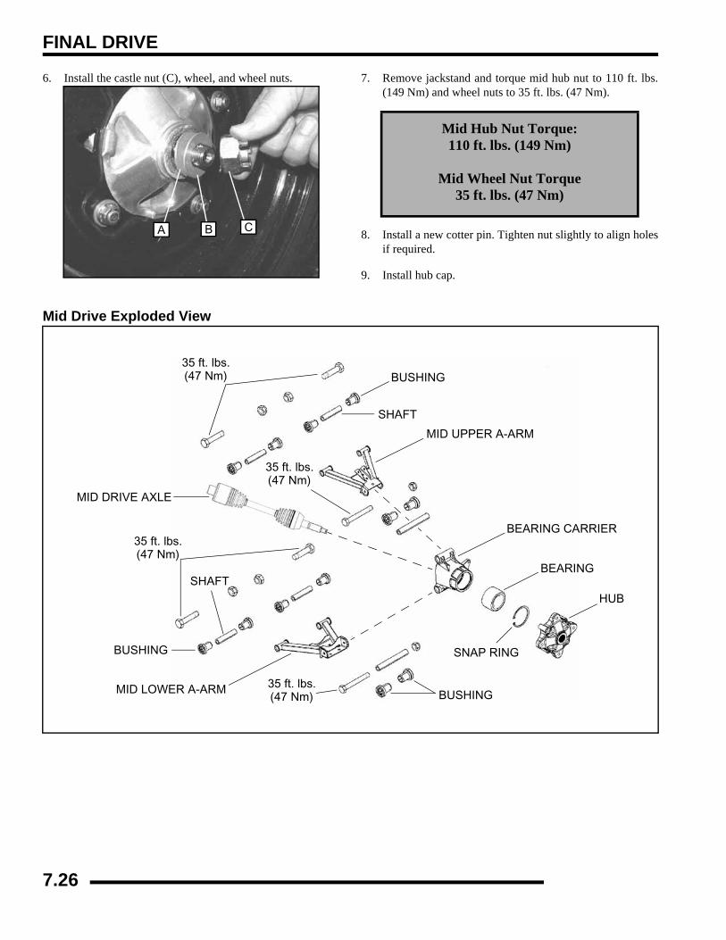
FINAL DRIVE
6. Install the castle nut (C), wheel, and wheel nuts. 7. Remove jackstand and torque mid hub nut to 110 ft. lbs.(149 Nm) and wheel nuts to 35 ft. lbs. (47 Nm).
8. Install a new cotter pin. Tighten nut slightly to align holesif required.
9. Install hub cap.
Mid Drive Exploded View
A B C
Mid Hub Nut Torque:110 ft. lbs. (149 Nm)
Mid Wheel Nut Torque35 ft. lbs. (47 Nm)
BUSHING
MID UPPER A-ARM
BEARING CARRIER
BEARING
SNAP RING
HUB
MID LOWER A-ARM
SHAFT
MID DRIVE AXLE
BUSHING
BUSHING35 ft. lbs.(47 Nm)
35 ft. lbs.(47 Nm)
35 ft. lbs.(47 Nm)
35 ft. lbs.(47 Nm)
SHAFT
7.26

FINAL DRIVE
7
MID DRIVE SHAFT (6X6)Removal1. Repeat Steps 1-7 in the “Mid Drive Hub / Bearing Carrier
Removal” section.
2. Slide the middle axle out of the bearing carrier by pullingthe bearing carrier assembly outward and down.
3. Pull the middle axle straight out from the frame. The axlewill slide off the mid gearcase splined output shaft.
Disassembly / Assembly
NOTE: For mid drive shaft service information, see“REAR DRIVE SHAFT (4X4) - CV Joint / BootReplacement”
Installation1. Apply Anti-Seize compound onto the mid gearcase output
shaft splines. Slide mid drive shaft (A) onto the midgearcase output shaft (B).
2. Install the outer end of the mid drive shaft into the hubcarrier (C).
3. Lift hub carrier into place and install bolt to upper controlarm. Torque bolt to 35 ft. lbs. (47 Nm).
4. Pull drive shaft outward and install hub onto driveshaftsplines. Apply Anti-Seize compound to the axle splines.
5. Install the flat washer (A) and cone washer (B) with domedside facing outward. (Refer to next photo)
AB
C
Upper Bolt
7.27

FINAL DRIVE
6. Install the castle nut (C), wheel, and wheel nuts.
7. Remove jackstand and torque mid hub nut to 110 ft. lbs.(149 Nm) and wheel nuts to 35 ft. lbs. (47 Nm).
8. Install a new cotter pin. Tighten nut slightly to align holesif required.
9. Install hub cap.
MID PROP SHAFT (6X6)Removal1. Use the Roll Pin Removal Tool (PN 2872608), to remove
the roll pin from prop shaft at rear of transmission.
2. The transmission or middle differential mounting will haveto be loosened to allow the propshaft to slide off of thetransmission output shaft.
MID DRIVE GEARCASE (6X6)Gearcase Removal
Mid Hub Nut Torque:110 ft. lbs. (149 Nm)
Mid Wheel Nut Torque35 ft. lbs. (47 Nm)
A B C
MID DRIVE GEARCASE
MID DRIVE SHAFT
PIN
TRANSMISSION
REAR DRIVE SHAFT
MOUNTING BOLTS
PIN
COUPLER
& WASHERS
7.28
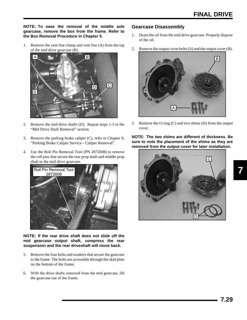
FINAL DRIVE
7
NOTE: To ease the removal of the middle axlegearcase, remove the box from the frame. Refer tothe Box Removal Procedure in Chapter 5.
1. Remove the vent line clamp and vent line (A) from the topof the mid drive gearcase (B).
2. Remove the mid drive shafts (D). Repeat steps 1-3 in the“Mid Drive Shaft Removal” section.
3. Remove the parking brake caliper (C), refer to Chapter 9,“Parking Brake Caliper Service - Caliper Removal”.
4. Use the Roll Pin Removal Tool (PN 2872608) to removethe roll pins that secure the rear prop shaft and middle propshaft to the mid drive gearcase.
NOTE: If the rear drive shaft does not slide off themid gearcase output shaft, compress the rearsuspension and the rear driveshaft will move back.
5. Remove the four bolts and washers that secure the gearcaseto the frame. The bolts are accessible through the skid plateon the bottom of the frame.
6. With the drive shafts removed from the mid gearcase, liftthe gearcase out of the frame.
Gearcase Disassembly1. Drain the oil from the mid drive gearcase. Properly dispose
of the oil.
2. Remove the output cover bolts (A) and the output cover (B).
3. Remove the O-ring (C) and two shims (D) from the outputcover.
NOTE: The two shims are different of thickness. Besure to note the placement of the shims as they areremoved from the output cover for later installation.
A B
DD C
Roll Pin Removal Tool2872608
A
B
D
C
7.29
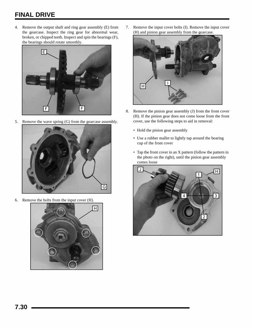
FINAL DRIVE
4. Remove the output shaft and ring gear assembly (E) fromthe gearcase. Inspect the ring gear for abnormal wear,broken, or chipped teeth. Inspect and spin the bearings (F),the bearings should rotate smoothly.
5. Remove the wave spring (G) from the gearcase assembly.
6. Remove the bolts from the input cover (H).
7. Remove the input cover bolts (I). Remove the input cover(H) and pinion gear assembly from the gearcase.
8. Remove the pinion gear assembly (J) from the front cover(H). If the pinion gear does not come loose from the frontcover, use the following steps to aid in removal:
• Hold the pinion gear assembly
• Use a rubber mallet to lightly tap around the bearing cup of the front cover
• Tap the front cover in an X pattern (follow the pattern in the photo on the right), until the pinion gear assembly comes loose
E
F F
G
H
IH
J H
2
1
34
7.30
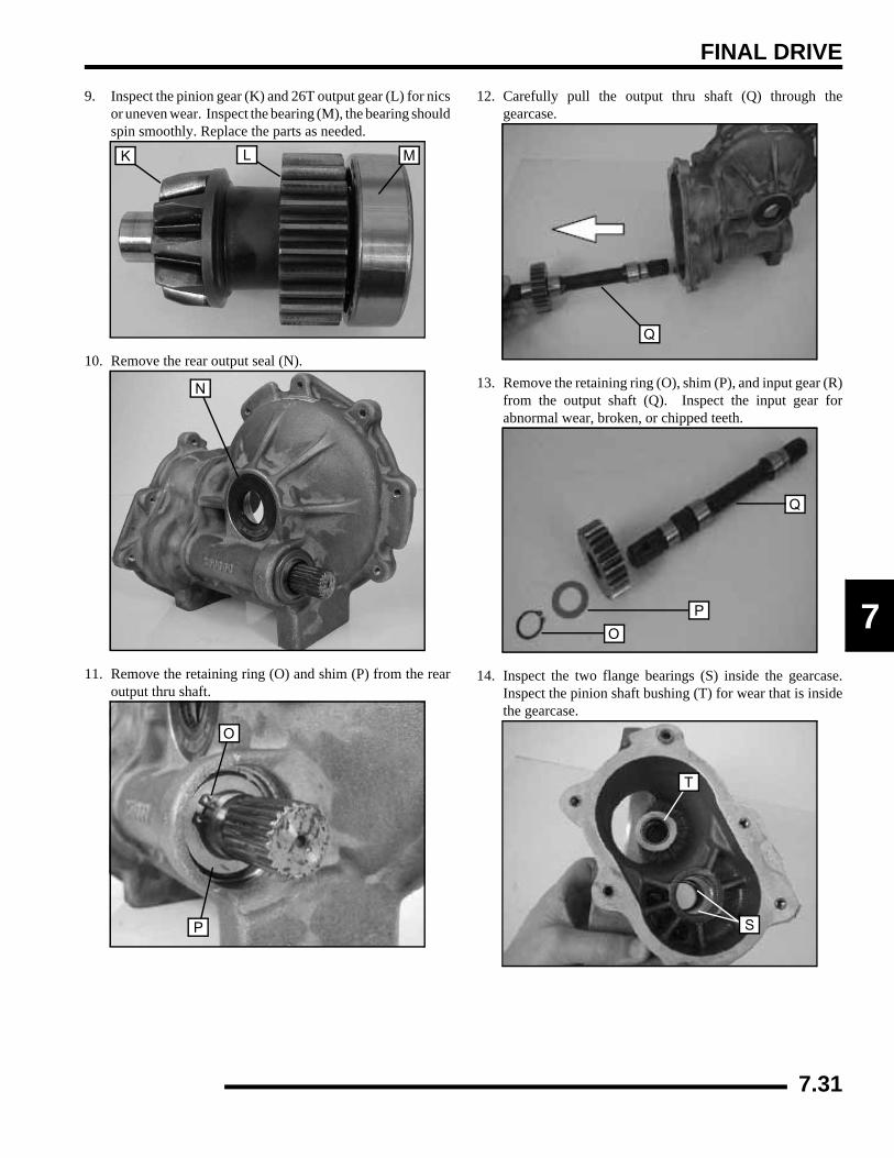
FINAL DRIVE
7
9. Inspect the pinion gear (K) and 26T output gear (L) for nicsor uneven wear. Inspect the bearing (M), the bearing shouldspin smoothly. Replace the parts as needed.
10. Remove the rear output seal (N).
11. Remove the retaining ring (O) and shim (P) from the rearoutput thru shaft.
12. Carefully pull the output thru shaft (Q) through thegearcase.
13. Remove the retaining ring (O), shim (P), and input gear (R)from the output shaft (Q). Inspect the input gear forabnormal wear, broken, or chipped teeth.
14. Inspect the two flange bearings (S) inside the gearcase.Inspect the pinion shaft bushing (T) for wear that is insidethe gearcase.
K L M
N
O
P
Q
Q
P
O
S
T
7.31
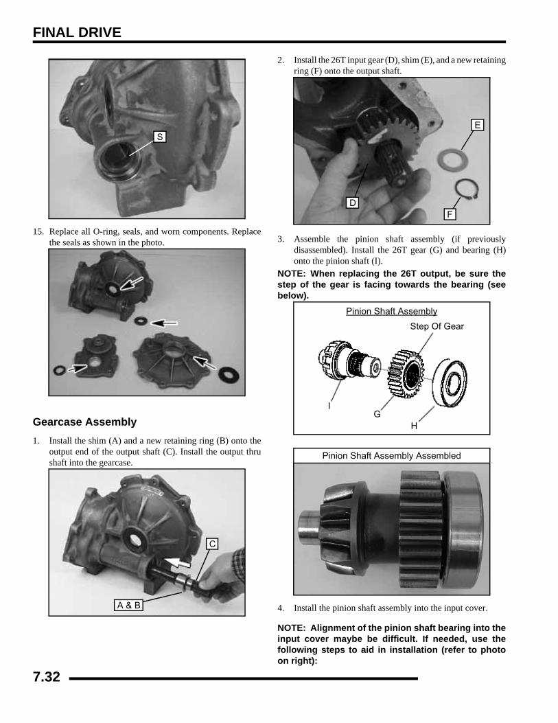
FINAL DRIVE
15. Replace all O-ring, seals, and worn components. Replacethe seals as shown in the photo.
Gearcase Assembly1. Install the shim (A) and a new retaining ring (B) onto the
output end of the output shaft (C). Install the output thrushaft into the gearcase.
2. Install the 26T input gear (D), shim (E), and a new retainingring (F) onto the output shaft.
3. Assemble the pinion shaft assembly (if previouslydisassembled). Install the 26T gear (G) and bearing (H)onto the pinion shaft (I).
NOTE: When replacing the 26T output, be sure thestep of the gear is facing towards the bearing (seebelow).
4. Install the pinion shaft assembly into the input cover.
NOTE: Alignment of the pinion shaft bearing into theinput cover maybe be difficult. If needed, use thefollowing steps to aid in installation (refer to photoon right):
S
A & B
C
D
E
F
Pinion Shaft Assembly
Step Of Gear
IG
H
Pinion Shaft Assembly Assembled
7.32
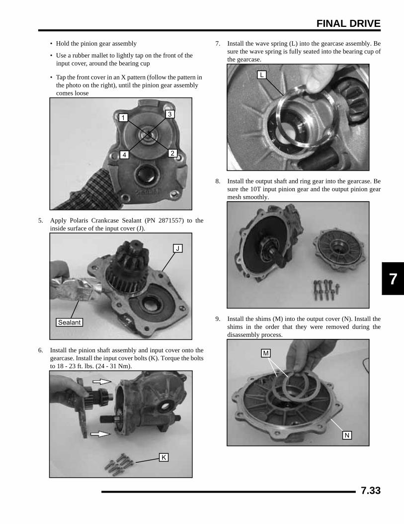
FINAL DRIVE
7
• Hold the pinion gear assembly
• Use a rubber mallet to lightly tap on the front of the input cover, around the bearing cup
• Tap the front cover in an X pattern (follow the pattern in the photo on the right), until the pinion gear assembly comes loose
5. Apply Polaris Crankcase Sealant (PN 2871557) to theinside surface of the input cover (J).
6. Install the pinion shaft assembly and input cover onto thegearcase. Install the input cover bolts (K). Torque the boltsto 18 - 23 ft. lbs. (24 - 31 Nm).
7. Install the wave spring (L) into the gearcase assembly. Besure the wave spring is fully seated into the bearing cup ofthe gearcase.
8. Install the output shaft and ring gear into the gearcase. Besure the 10T input pinion gear and the output pinion gearmesh smoothly.
9. Install the shims (M) into the output cover (N). Install theshims in the order that they were removed during thedisassembly process.
2
1
4
3
Sealant
J
K
L
M
N
7.33

FINAL DRIVE
10. Install a new O-ring (O) onto the output cover.
11. Carefully install the output cover onto the gearcase.Install the output cover bolts. Torque the bolts to 18 - 23ft. lbs. (24 - 31 Nm).
12. Remove the fill plug (P) and fill the mid gearcase with 6.75oz. (200 ml) of Polaris ATV Angle Drive Fluid(PN 2871653). Torque the fill plug to 14 ft. lbs. (19 Nm).
Gearcase Installation1. Place the middle gearcase in the frame assembly.
2. Attach the mid and rear prop shafts to the mid gearcase, butdo not install the new roll pins yet.
3. Install the four middle drive gearcase bolts. Torque thebolts to 30 ft. lbs. (41 Nm) in a cross pattern.
4. Install a new roll pins into the mid and rear prop shafts andmiddle gearcase input and rear output shafts.
5. Install the mid drive shafts (D) onto the mid gearcase (B).
6. Install the vent tube (A) and clamp.
7. Lift bearing carrier into place and install bolt to uppercontrol arm. Torque bolt to 35 ft. lbs. (47 Nm). Refer to the“MID DRIVE SHAFT INSTALLATION” section formore details.
8. Install hub, flat washer, domed washer (domed side out)and nut. Torque center nut to 110 ft. lbs. (149 Nm). Installnew cotter pin and hub cap.
9. Install rear wheel and torque wheel nuts to specification.
10. Install the parking brake caliper (C), refer to Chapter 9,“Parking Brake Caliper Service - Caliper Installation”
Input Cover Bolt Torque:
18 - 23 ft. lbs. (24 - 31 Nm)
O
P
Middle Gearcase Specifications:
Capacity: 6.75 oz. (200 ml)
Specified Lubricant: ATV Angle Drive Fluid (PN 2871653)
Fill Plug Torque: 14 ft. lbs. (19 Nm)
A B
DD C
7.34
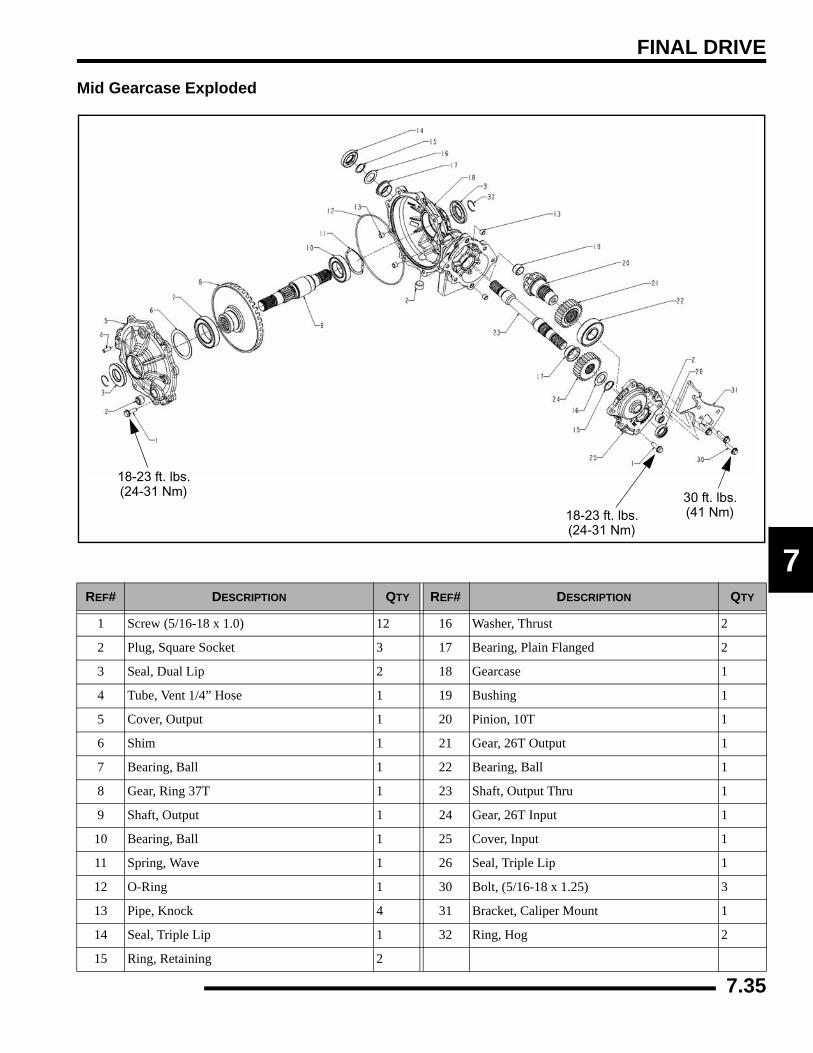
FINAL DRIVE
7
Mid Gearcase Exploded
REF# DESCRIPTION QTY REF# DESCRIPTION QTY
1 Screw (5/16-18 x 1.0) 12 16 Washer, Thrust 2
2 Plug, Square Socket 3 17 Bearing, Plain Flanged 2
3 Seal, Dual Lip 2 18 Gearcase 1
4 Tube, Vent 1/4” Hose 1 19 Bushing 1
5 Cover, Output 1 20 Pinion, 10T 1
6 Shim 1 21 Gear, 26T Output 1
7 Bearing, Ball 1 22 Bearing, Ball 1
8 Gear, Ring 37T 1 23 Shaft, Output Thru 1
9 Shaft, Output 1 24 Gear, 26T Input 1
10 Bearing, Ball 1 25 Cover, Input 1
11 Spring, Wave 1 26 Seal, Triple Lip 1
12 O-Ring 1 30 Bolt, (5/16-18 x 1.25) 3
13 Pipe, Knock 4 31 Bracket, Caliper Mount 1
14 Seal, Triple Lip 1 32 Ring, Hog 2
15 Ring, Retaining 2
18-23 ft. lbs.(24-31 Nm)
18-23 ft. lbs.(24-31 Nm) 30 ft. lbs.
(41 Nm)
7.35
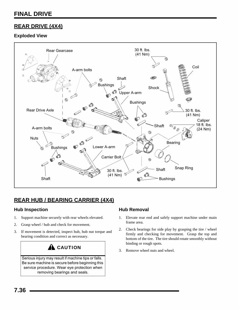
FINAL DRIVE
REAR DRIVE (4X4)Exploded View
REAR HUB / BEARING CARRIER (4X4)Hub Inspection1. Support machine securely with rear wheels elevated.
2. Grasp wheel / hub and check for movement.
3. If movement is detected, inspect hub, hub nut torque andbearing condition and correct as necessary.
Hub Removal1. Elevate rear end and safely support machine under main
frame area.
2. Check bearings for side play by grasping the tire / wheelfirmly and checking for movement. Grasp the top andbottom of the tire. The tire should rotate smoothly withoutbinding or rough spots.
3. Remove wheel nuts and wheel.
Rear Gearcase
A-arm bolts
Rear Drive Axle
A-arm bolts
Nuts
Bushings Lower A-arm
Carrier Bolt
Shaft
Bushings
Snap Ring
Coil
30 ft. lbs.(41 Nm)
Shock
Shaft
Bearing
Bushings
30 ft. lbs.(41 Nm)
Bushings
Shaft
Upper A-arm
Caliper18 ft. lbs.(24 Nm)
30 ft. lbs.(41 Nm)
CAUTION
Serious injury may result if machine tips or falls. Be sure machine is secure before beginning this service procedure. Wear eye protection when
removing bearings and seals.
7.36
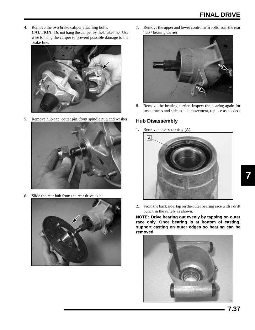
FINAL DRIVE
7
4. Remove the two brake caliper attaching bolts. CAUTION: Do not hang the caliper by the brake line. Usewire to hang the caliper to prevent possible damage to thebrake line.
5. Remove hub cap, cotter pin, front spindle nut, and washer.
6. Slide the rear hub from the rear drive axle.
7. Remove the upper and lower control arm bolts from the rearhub / bearing carrier.
8. Remove the bearing carrier. Inspect the bearing again forsmoothness and side to side movement, replace as needed.
Hub Disassembly1. Remove outer snap ring (A).
2. From the back side, tap on the outer bearing race with a driftpunch in the reliefs as shown.
NOTE: Drive bearing out evenly by tapping on outerrace only. Once bearing is at bottom of casting,support casting on outer edges so bearing can beremoved.
A
7.37
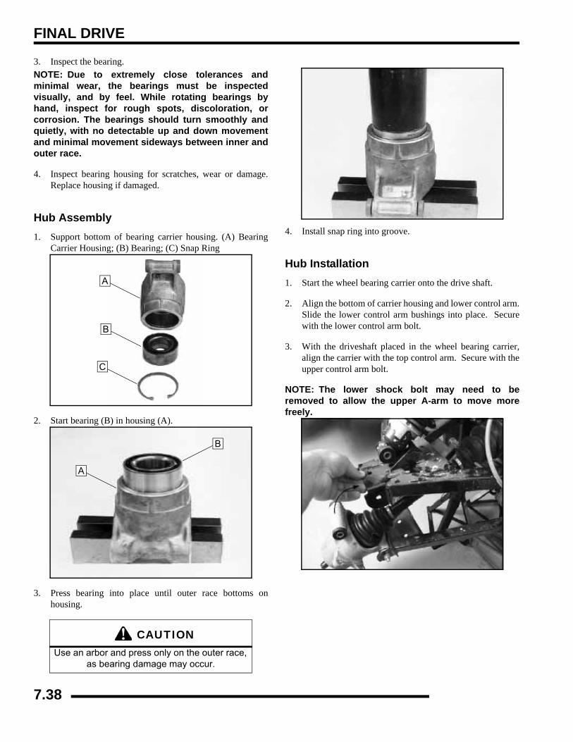
FINAL DRIVE
3. Inspect the bearing.NOTE: Due to extremely close tolerances andminimal wear, the bearings must be inspectedvisually, and by feel. While rotating bearings byhand, inspect for rough spots, discoloration, orcorrosion. The bearings should turn smoothly andquietly, with no detectable up and down movementand minimal movement sideways between inner andouter race.
4. Inspect bearing housing for scratches, wear or damage.Replace housing if damaged.
Hub Assembly1. Support bottom of bearing carrier housing. (A) Bearing
Carrier Housing; (B) Bearing; (C) Snap Ring
2. Start bearing (B) in housing (A).
3. Press bearing into place until outer race bottoms onhousing.
4. Install snap ring into groove.
Hub Installation1. Start the wheel bearing carrier onto the drive shaft.
2. Align the bottom of carrier housing and lower control arm.Slide the lower control arm bushings into place. Securewith the lower control arm bolt.
3. With the driveshaft placed in the wheel bearing carrier,align the carrier with the top control arm. Secure with theupper control arm bolt.
NOTE: The lower shock bolt may need to beremoved to allow the upper A-arm to move morefreely.
CAUTIONUse an arbor and press only on the outer race,
as bearing damage may occur.
A
B
C
B
A
7.38
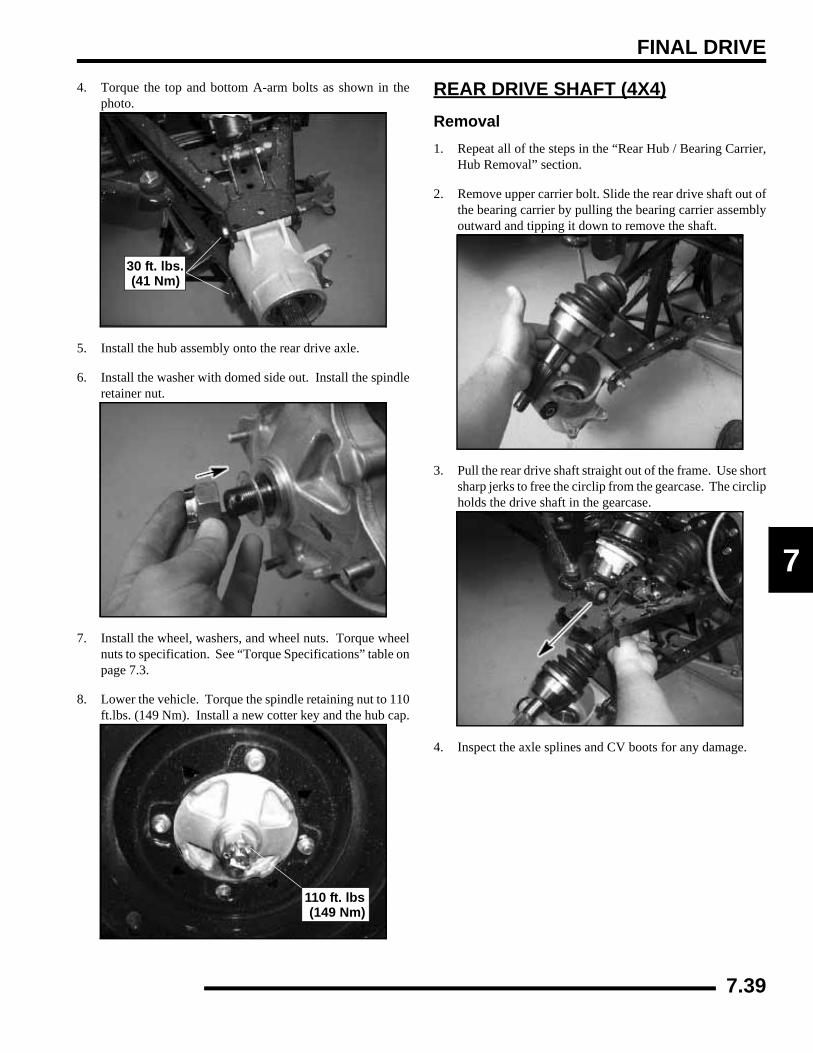
FINAL DRIVE
7
4. Torque the top and bottom A-arm bolts as shown in thephoto.
5. Install the hub assembly onto the rear drive axle.
6. Install the washer with domed side out. Install the spindleretainer nut.
7. Install the wheel, washers, and wheel nuts. Torque wheelnuts to specification. See “Torque Specifications” table onpage 7.3.
8. Lower the vehicle. Torque the spindle retaining nut to 110ft.lbs. (149 Nm). Install a new cotter key and the hub cap.
REAR DRIVE SHAFT (4X4)Removal1. Repeat all of the steps in the “Rear Hub / Bearing Carrier,
Hub Removal” section.
2. Remove upper carrier bolt. Slide the rear drive shaft out ofthe bearing carrier by pulling the bearing carrier assemblyoutward and tipping it down to remove the shaft.
3. Pull the rear drive shaft straight out of the frame. Use shortsharp jerks to free the circlip from the gearcase. The circlipholds the drive shaft in the gearcase.
4. Inspect the axle splines and CV boots for any damage.
30 ft. lbs.(41 Nm)
110 ft. lbs(149 Nm)
7.39
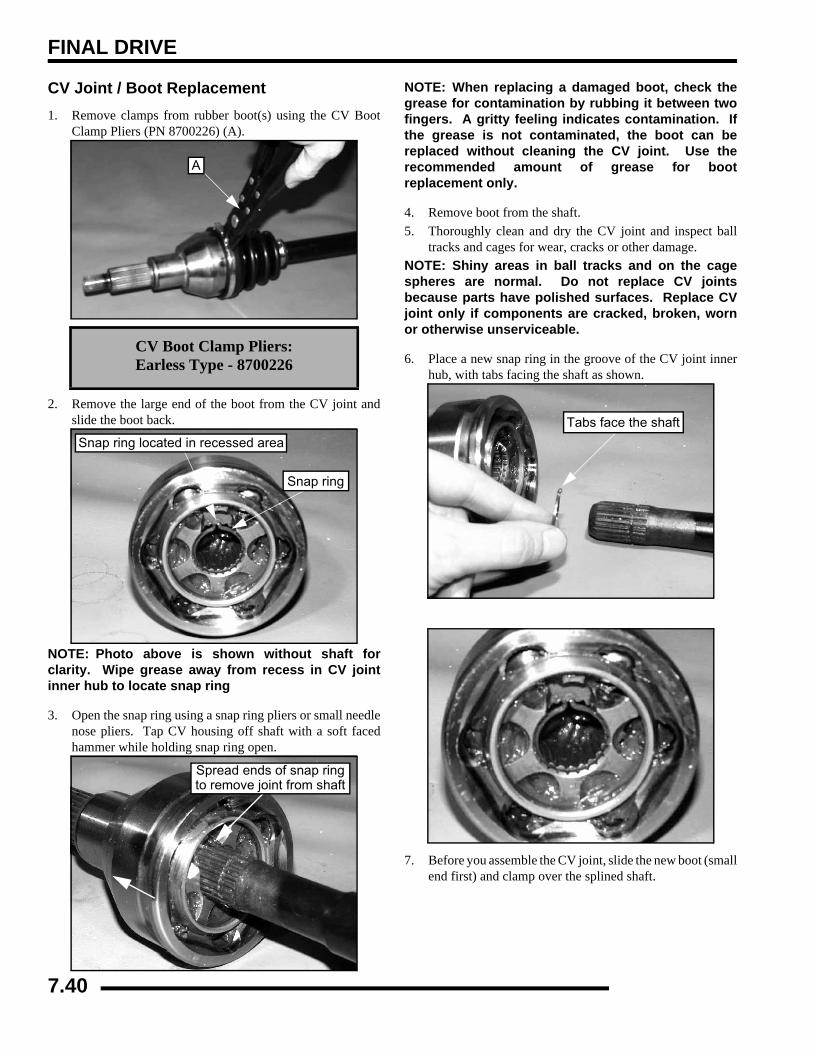
FINAL DRIVE
CV Joint / Boot Replacement1. Remove clamps from rubber boot(s) using the CV Boot
Clamp Pliers (PN 8700226) (A).
2. Remove the large end of the boot from the CV joint andslide the boot back.
NOTE: Photo above is shown without shaft forclarity. Wipe grease away from recess in CV jointinner hub to locate snap ring
3. Open the snap ring using a snap ring pliers or small needlenose pliers. Tap CV housing off shaft with a soft facedhammer while holding snap ring open.
NOTE: When replacing a damaged boot, check thegrease for contamination by rubbing it between twofingers. A gritty feeling indicates contamination. Ifthe grease is not contaminated, the boot can bereplaced without cleaning the CV joint. Use therecommended amount of grease for bootreplacement only.
4. Remove boot from the shaft.5. Thoroughly clean and dry the CV joint and inspect ball
tracks and cages for wear, cracks or other damage.NOTE: Shiny areas in ball tracks and on the cagespheres are normal. Do not replace CV jointsbecause parts have polished surfaces. Replace CVjoint only if components are cracked, broken, wornor otherwise unserviceable.
6. Place a new snap ring in the groove of the CV joint innerhub, with tabs facing the shaft as shown.
7. Before you assemble the CV joint, slide the new boot (smallend first) and clamp over the splined shaft.
CV Boot Clamp Pliers:Earless Type - 8700226
A
Snap ring
Snap ring located in recessed area
Spread ends of snap ringto remove joint from shaft
Tabs face the shaft
7.40
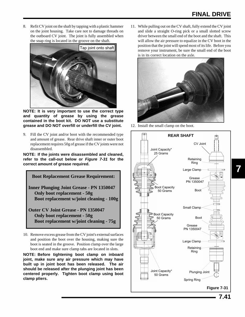
FINAL DRIVE
7
8. Refit CV joint on the shaft by tapping with a plastic hammeron the joint housing. Take care not to damage threads onthe outboard CV joint. The joint is fully assembled whenthe snap ring is located in the groove on the shaft.
NOTE: It is very important to use the correct typeand quantity of grease by using the greasecontained in the boot kit. DO NOT use a substitutegrease and DO NOT overfill or underfill the CV joint.
9. Fill the CV joint and/or boot with the recommended typeand amount of grease. Rear drive shaft inner or outer bootreplacement requires 50g of grease if the CV joints were notdisassembled.
NOTE: If the joints were disassembled and cleaned,refer to the call-out below or Figure 7-31 for thecorrect amount of grease required.
10. Remove excess grease from the CV joint's external surfacesand position the boot over the housing, making sure theboot is seated in the groove. Position clamp over the largeboot end and make sure clamp tabs are located in slots.
NOTE: Before tightening boot clamp on inboardjoint, make sure any air pressure which may havebuilt up in joint boot has been released. The airshould be released after the plunging joint has beencentered properly. Tighten boot clamp using bootclamp pliers.
11. While pulling out on the CV shaft, fully extend the CV jointand slide a straight O-ring pick or a small slotted screwdriver between the small end of the boot and the shaft. Thiswill allow the air pressure to equalize in the CV boot in theposition that the joint will spend most of its life. Before youremove your instrument, be sure the small end of the bootis in its correct location on the axle.
12. Install the small clamp on the boot.
Boot Replacement Grease Requirement:
Inner Plunging Joint Grease - PN 1350047 Only boot replacement - 50g Boot replacement w/joint cleaning - 100g
Outer CV Joint Grease - PN 1350047 Only boot replacement - 50g Boot replacement w/joint cleaning - 75g
Tap joint onto shaft
REAR SHAFT
Joint Capacity*25 Grams
Boot Capacity50 Grams
Boot Capacity50 Grams
Joint Capacity*50 Grams
CV Joint
Figure 7-31
RetainingRing
Large Clamp
GreasePN 1350047
Boot
Small Clamp
Boot
GreasePN 1350047
Large Clamp
RetainingRing
Plunging Joint
Spring Ring
7.41
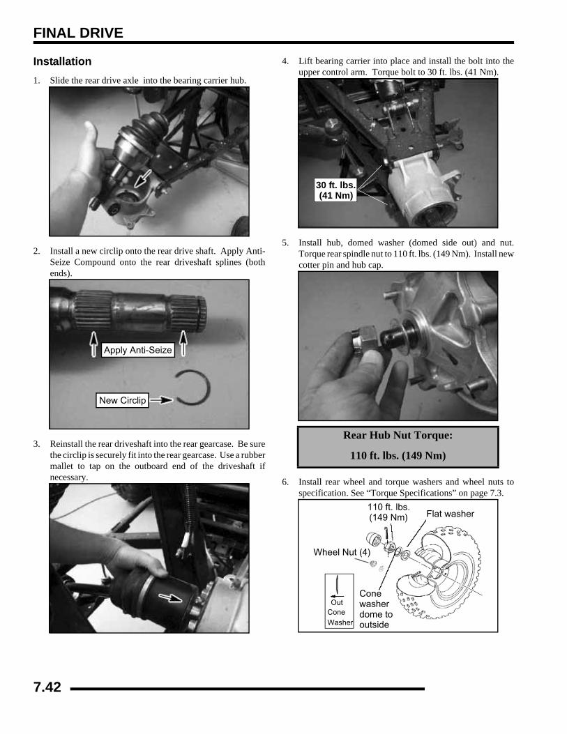
FINAL DRIVE
Installation1. Slide the rear drive axle into the bearing carrier hub.
2. Install a new circlip onto the rear drive shaft. Apply Anti-Seize Compound onto the rear driveshaft splines (bothends).
3. Reinstall the rear driveshaft into the rear gearcase. Be surethe circlip is securely fit into the rear gearcase. Use a rubbermallet to tap on the outboard end of the driveshaft ifnecessary.
4. Lift bearing carrier into place and install the bolt into theupper control arm. Torque bolt to 30 ft. lbs. (41 Nm).
5. Install hub, domed washer (domed side out) and nut.Torque rear spindle nut to 110 ft. lbs. (149 Nm). Install newcotter pin and hub cap.
6. Install rear wheel and torque washers and wheel nuts tospecification. See “Torque Specifications” on page 7.3.
Apply Anti-Seize
New Circlip
Rear Hub Nut Torque:
110 ft. lbs. (149 Nm)
30 ft. lbs.(41 Nm)
110 ft. lbs.(149 Nm) Flat washer
Wheel Nut (4)
Cone
dome to Out
Cone Washer
washer
outside
7.42
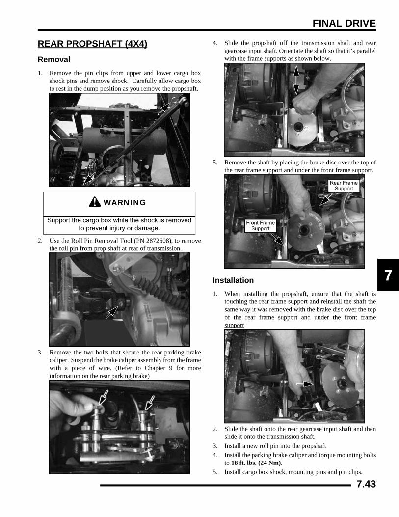
FINAL DRIVE
7
REAR PROPSHAFT (4X4)Removal1. Remove the pin clips from upper and lower cargo box
shock pins and remove shock. Carefully allow cargo boxto rest in the dump position as you remove the propshaft.
2. Use the Roll Pin Removal Tool (PN 2872608), to removethe roll pin from prop shaft at rear of transmission.
3. Remove the two bolts that secure the rear parking brakecaliper. Suspend the brake caliper assembly from the framewith a piece of wire. (Refer to Chapter 9 for moreinformation on the rear parking brake)
4. Slide the propshaft off the transmission shaft and reargearcase input shaft. Orientate the shaft so that it’s parallelwith the frame supports as shown below.
5. Remove the shaft by placing the brake disc over the top ofthe rear frame support and under the front frame support.
Installation1. When installing the propshaft, ensure that the shaft is
touching the rear frame support and reinstall the shaft thesame way it was removed with the brake disc over the topof the rear frame support and under the front framesupport.
2. Slide the shaft onto the rear gearcase input shaft and thenslide it onto the transmission shaft.
3. Install a new roll pin into the propshaft4. Install the parking brake caliper and torque mounting bolts
to 18 ft. lbs. (24 Nm).5. Install cargo box shock, mounting pins and pin clips.
WARNING
Support the cargo box while the shock is removed to prevent injury or damage.
Front FrameSupport
Rear FrameSupport
7.43
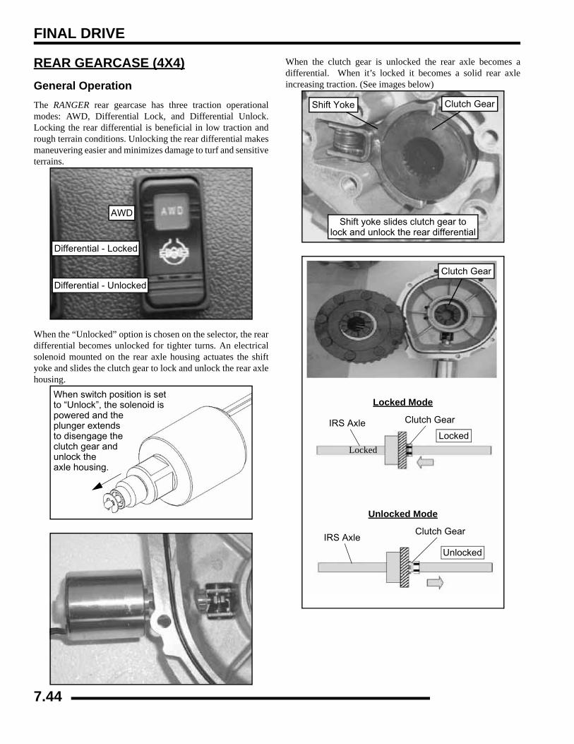
FINAL DRIVE
REAR GEARCASE (4X4)General OperationThe RANGER rear gearcase has three traction operationalmodes: AWD, Differential Lock, and Differential Unlock.Locking the rear differential is beneficial in low traction andrough terrain conditions. Unlocking the rear differential makesmaneuvering easier and minimizes damage to turf and sensitiveterrains.
When the “Unlocked” option is chosen on the selector, the reardifferential becomes unlocked for tighter turns. An electricalsolenoid mounted on the rear axle housing actuates the shiftyoke and slides the clutch gear to lock and unlock the rear axlehousing.
When the clutch gear is unlocked the rear axle becomes adifferential. When it’s locked it becomes a solid rear axleincreasing traction. (See images below)
AWD
Differential - Unlocked
Differential - Locked
When switch position is setto “Unlock”, the solenoid ispowered and the plunger extendsto disengage theclutch gear andunlock theaxle housing.
Shift yoke slides clutch gear tolock and unlock the rear differential
Clutch GearShift Yoke
IRS AxleClutch Gear
Locked
Unlocked
Locked Mode
Unlocked Mode
IRS Axle Clutch Gear
Locked
Clutch Gear
7.44
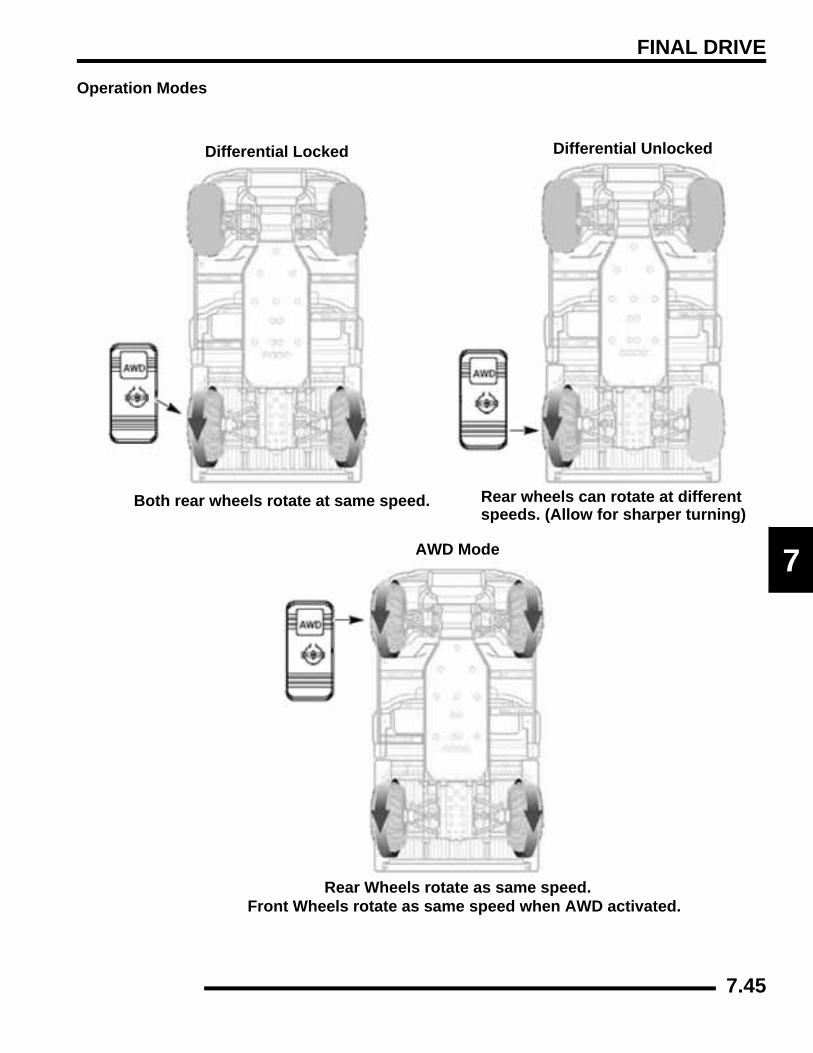
FINAL DRIVE
7
Operation Modes
Differential Locked Differential Unlocked
AWD Mode
Both rear wheels rotate at same speed. Rear wheels can rotate at differentspeeds. (Allow for sharper turning)
Rear Wheels rotate as same speed.Front Wheels rotate as same speed when AWD activated.
7.45
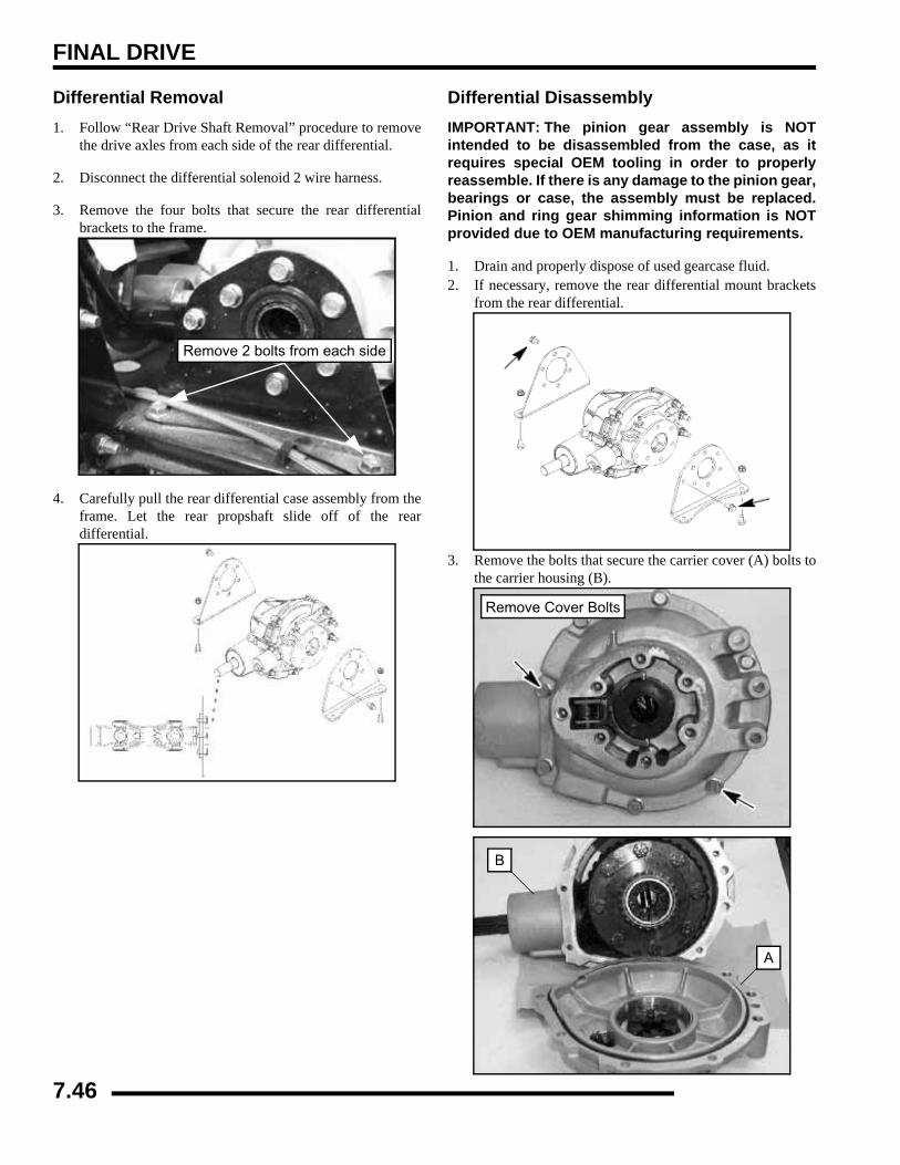
FINAL DRIVE
Differential Removal1. Follow “Rear Drive Shaft Removal” procedure to remove
the drive axles from each side of the rear differential.
2. Disconnect the differential solenoid 2 wire harness.
3. Remove the four bolts that secure the rear differentialbrackets to the frame.
4. Carefully pull the rear differential case assembly from theframe. Let the rear propshaft slide off of the reardifferential.
Differential DisassemblyIMPORTANT: The pinion gear assembly is NOTintended to be disassembled from the case, as itrequires special OEM tooling in order to properlyreassemble. If there is any damage to the pinion gear,bearings or case, the assembly must be replaced.Pinion and ring gear shimming information is NOTprovided due to OEM manufacturing requirements.
1. Drain and properly dispose of used gearcase fluid.2. If necessary, remove the rear differential mount brackets
from the rear differential.
3. Remove the bolts that secure the carrier cover (A) bolts tothe carrier housing (B).
Remove 2 bolts from each side
Remove Cover Bolts
B
A
7.46
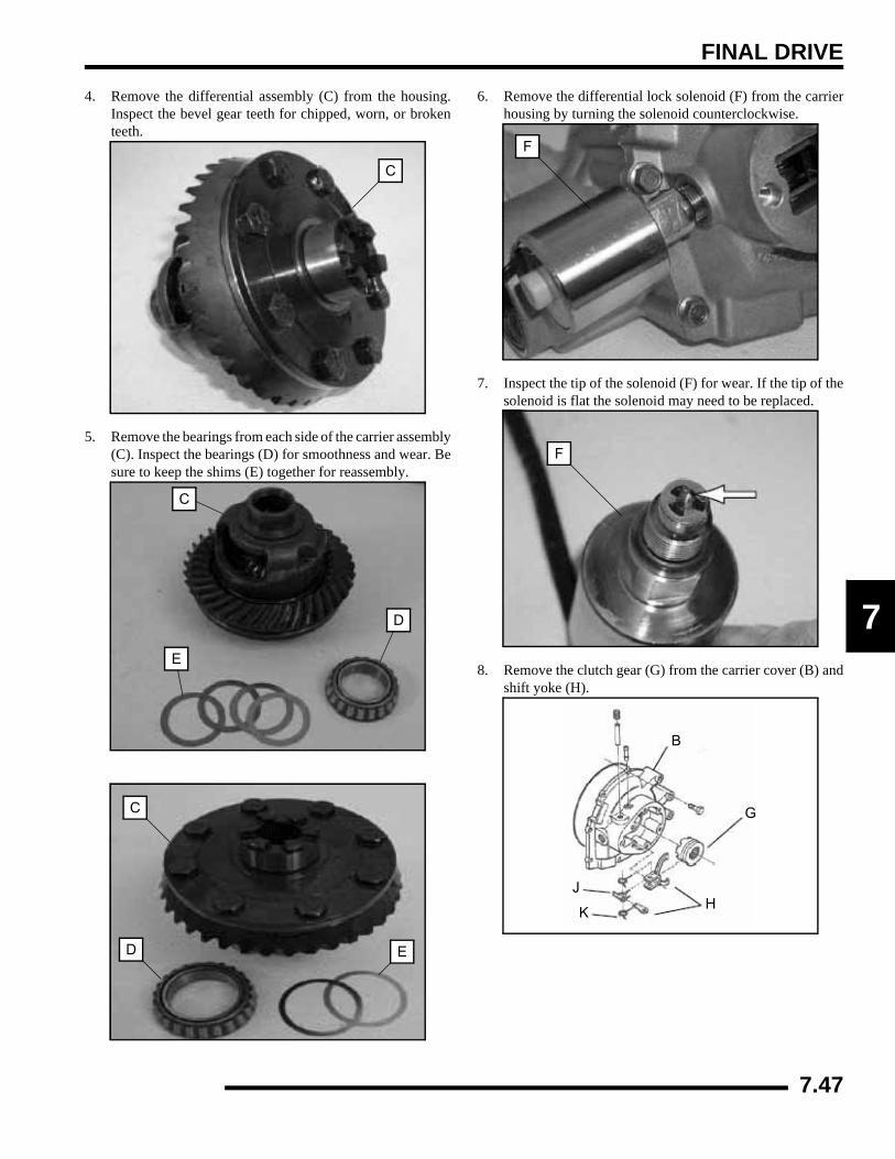
FINAL DRIVE
7
4. Remove the differential assembly (C) from the housing.Inspect the bevel gear teeth for chipped, worn, or brokenteeth.
5. Remove the bearings from each side of the carrier assembly(C). Inspect the bearings (D) for smoothness and wear. Besure to keep the shims (E) together for reassembly.
6. Remove the differential lock solenoid (F) from the carrierhousing by turning the solenoid counterclockwise.
7. Inspect the tip of the solenoid (F) for wear. If the tip of thesolenoid is flat the solenoid may need to be replaced.
8. Remove the clutch gear (G) from the carrier cover (B) andshift yoke (H).
C
C
E
D
C
D E
F
F
B
G
J
KH
7.47
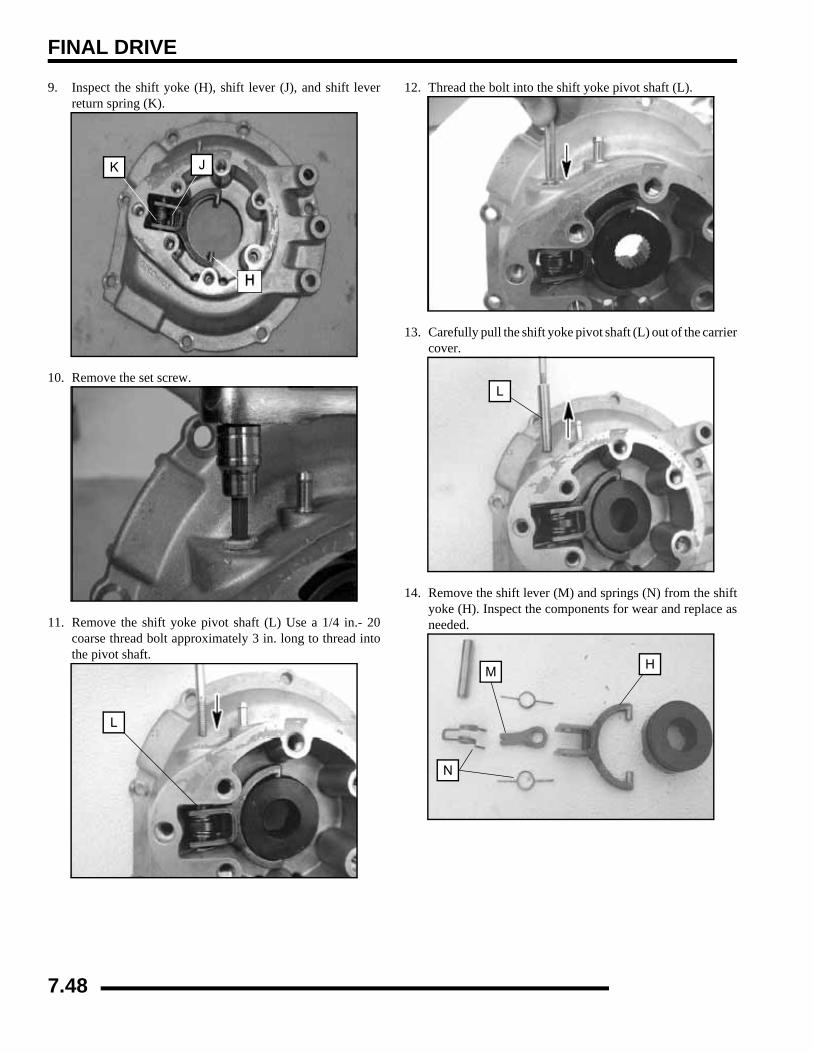
FINAL DRIVE
9. Inspect the shift yoke (H), shift lever (J), and shift leverreturn spring (K).
10. Remove the set screw.
11. Remove the shift yoke pivot shaft (L) Use a 1/4 in.- 20coarse thread bolt approximately 3 in. long to thread intothe pivot shaft.
12. Thread the bolt into the shift yoke pivot shaft (L).
13. Carefully pull the shift yoke pivot shaft (L) out of the carriercover.
14. Remove the shift lever (M) and springs (N) from the shiftyoke (H). Inspect the components for wear and replace asneeded.
H
JK
L
L
M
N
H
7.48
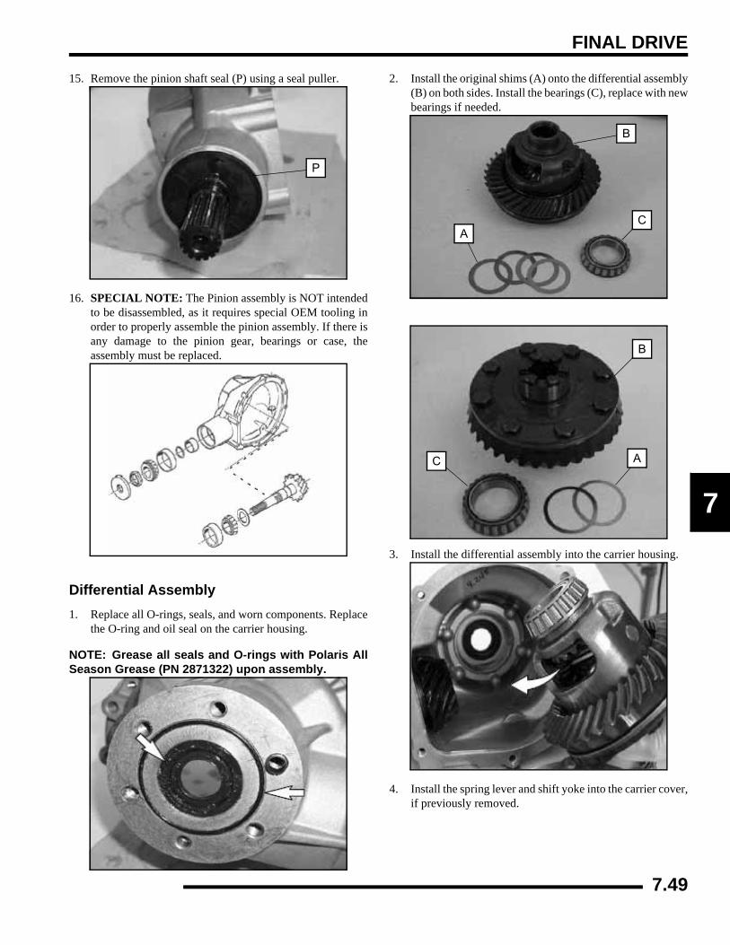
FINAL DRIVE
7
15. Remove the pinion shaft seal (P) using a seal puller.
16. SPECIAL NOTE: The Pinion assembly is NOT intendedto be disassembled, as it requires special OEM tooling inorder to properly assemble the pinion assembly. If there isany damage to the pinion gear, bearings or case, theassembly must be replaced.
Differential Assembly1. Replace all O-rings, seals, and worn components. Replace
the O-ring and oil seal on the carrier housing.
NOTE: Grease all seals and O-rings with Polaris AllSeason Grease (PN 2871322) upon assembly.
2. Install the original shims (A) onto the differential assembly(B) on both sides. Install the bearings (C), replace with newbearings if needed.
3. Install the differential assembly into the carrier housing.
4. Install the spring lever and shift yoke into the carrier cover,if previously removed.
P
AC
B
B
AC
7.49

FINAL DRIVE
5. Assemble the shift yoke (D), shift lever (G), spring lever(F), and return spring (E).
6. Use the bolt that was used to remove the shift yoke pivotshaft (H) to reinsert the shaft into the carrier cover. Placethe shift yoke assembly into the carrier cover and securewith the shift yoke pivot shaft (H).
7. Install the differential lock solenoid into the carrier cover.Torque solenoid to 30-40 ft. lbs. (41-54 Nm).
8. Install the new lightly greased O-ring (K) onto the carriercover.
9. Install the carrier cover bolts. Tighten and torque the boltsin a criss cross pattern to 25-35 ft.lbs. (34-48 Nm).
10. Install the rear differential mount brackets from the reardifferential onto the rear differential. Torque the bracket todifferential bolts to 26-33 ft.lbs. (35-45 Nm)
H
F
E G D
Carrier Cover
Install Shift Yoke Assembly
30-40 ft. lbs.(41-54 Nm)
K
25-35 ft. lbs.(34-48 Nm)
26-33 ft. lbs. (35-45 Nm)Bracket to Differential
7.50
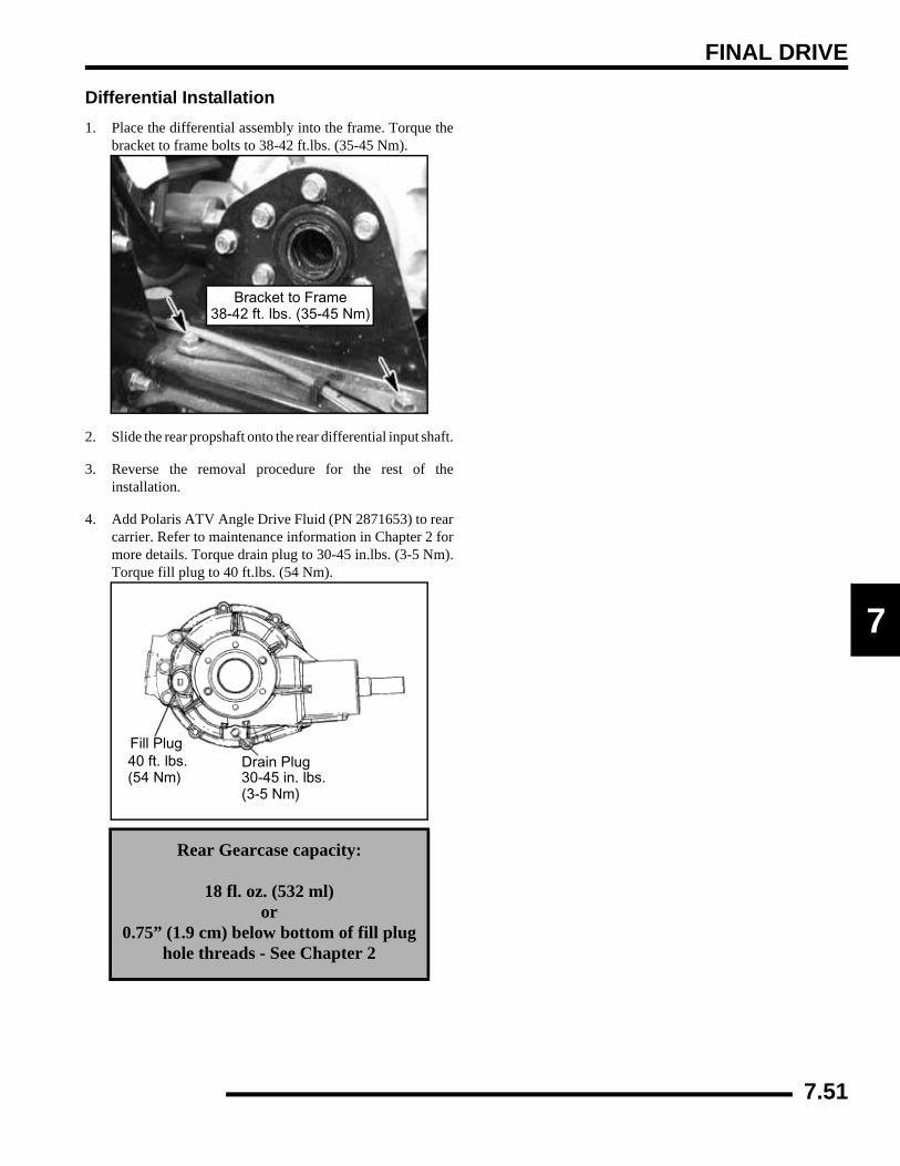
FINAL DRIVE
7
Differential Installation1. Place the differential assembly into the frame. Torque the
bracket to frame bolts to 38-42 ft.lbs. (35-45 Nm).
2. Slide the rear propshaft onto the rear differential input shaft.
3. Reverse the removal procedure for the rest of theinstallation.
4. Add Polaris ATV Angle Drive Fluid (PN 2871653) to rearcarrier. Refer to maintenance information in Chapter 2 formore details. Torque drain plug to 30-45 in.lbs. (3-5 Nm).Torque fill plug to 40 ft.lbs. (54 Nm).
Rear Gearcase capacity:
18 fl. oz. (532 ml)or
0.75” (1.9 cm) below bottom of fill plug hole threads - See Chapter 2
Bracket to Frame38-42 ft. lbs. (35-45 Nm)
Fill PlugDrain Plug40 ft. lbs.
(54 Nm) 30-45 in. lbs.(3-5 Nm)
7.51
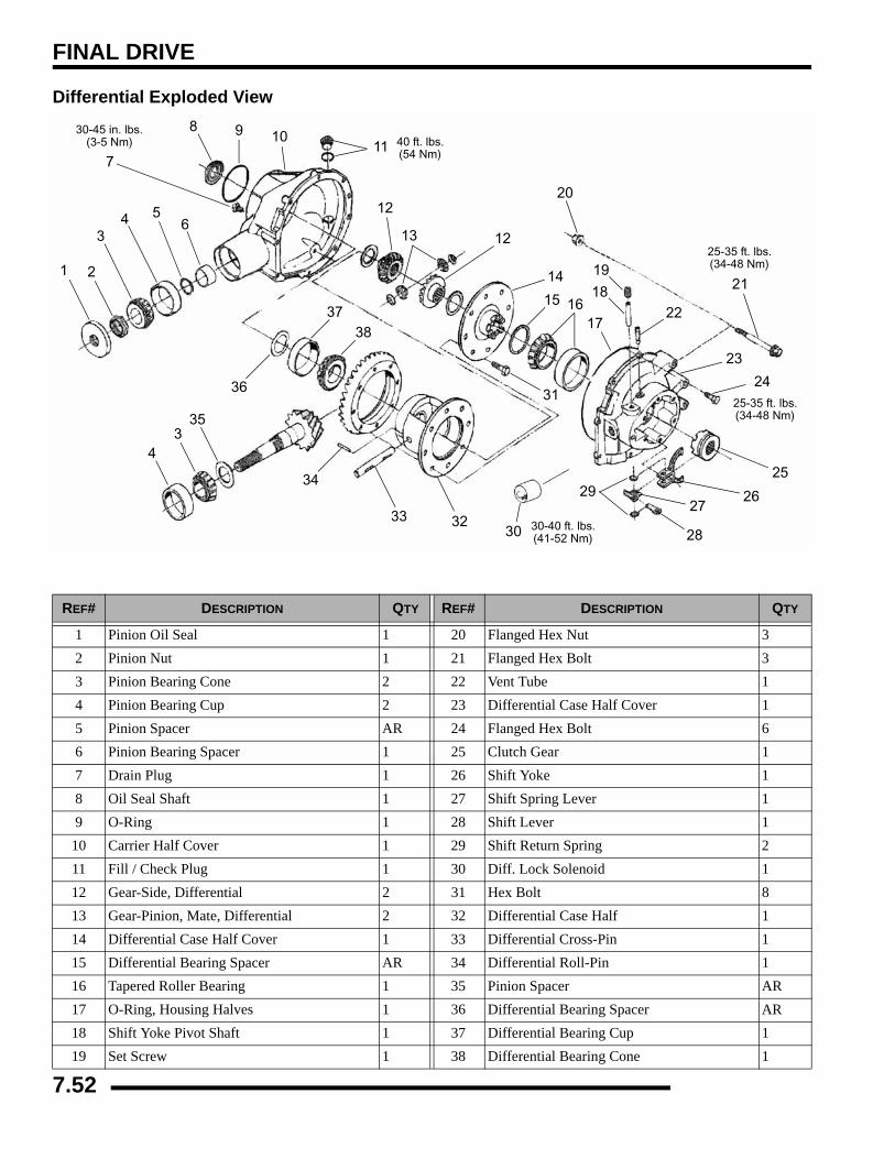
FINAL DRIVE
Differential Exploded View
REF# DESCRIPTION QTY REF# DESCRIPTION QTY
1 Pinion Oil Seal 1 20 Flanged Hex Nut 32 Pinion Nut 1 21 Flanged Hex Bolt 33 Pinion Bearing Cone 2 22 Vent Tube 14 Pinion Bearing Cup 2 23 Differential Case Half Cover 15 Pinion Spacer AR 24 Flanged Hex Bolt 66 Pinion Bearing Spacer 1 25 Clutch Gear 17 Drain Plug 1 26 Shift Yoke 18 Oil Seal Shaft 1 27 Shift Spring Lever 19 O-Ring 1 28 Shift Lever 1
10 Carrier Half Cover 1 29 Shift Return Spring 211 Fill / Check Plug 1 30 Diff. Lock Solenoid 112 Gear-Side, Differential 2 31 Hex Bolt 813 Gear-Pinion, Mate, Differential 2 32 Differential Case Half 114 Differential Case Half Cover 1 33 Differential Cross-Pin 115 Differential Bearing Spacer AR 34 Differential Roll-Pin 116 Tapered Roller Bearing 1 35 Pinion Spacer AR17 O-Ring, Housing Halves 1 36 Differential Bearing Spacer AR18 Shift Yoke Pivot Shaft 1 37 Differential Bearing Cup 119 Set Screw 1 38 Differential Bearing Cone 1
1 2
34 5
6
7
8 9 1011
12
13
14
15 1617
18
19
20
12
21
22
23
24
25
2627
28
29
30
31
3233
34
35
36
3738
34
30-45 in. lbs.(3-5 Nm) 40 ft. lbs.
(54 Nm)
25-35 ft. lbs.(34-48 Nm)
25-35 ft. lbs.(34-48 Nm)
30-40 ft. lbs.(41-52 Nm)
7.52
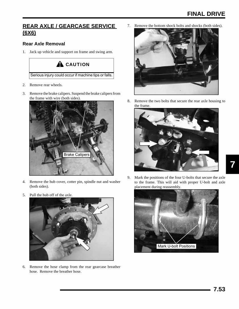
FINAL DRIVE
7
REAR AXLE / GEARCASE SERVICE (6X6)
Rear Axle Removal1. Jack up vehicle and support on frame and swing arm.
2. Remove rear wheels.
3. Remove the brake calipers. Suspend the brake calipers fromthe frame with wire (both sides).
4. Remove the hub cover, cotter pin, spindle nut and washer(both sides).
5. Pull the hub off of the axle.
6. Remove the hose clamp from the rear gearcase breatherhose. Remove the breather hose.
7. Remove the bottom shock bolts and shocks (both sides).
8. Remove the two bolts that secure the rear axle housing tothe frame.
9. Mark the positions of the four U-bolts that secure the axleto the frame. This will aid with proper U-bolt and axleplacement during reassembly.
CAUTION
Serious injury could occur if machine tips or falls.
Brake Calipers
Mark U-bolt Positions
7.53
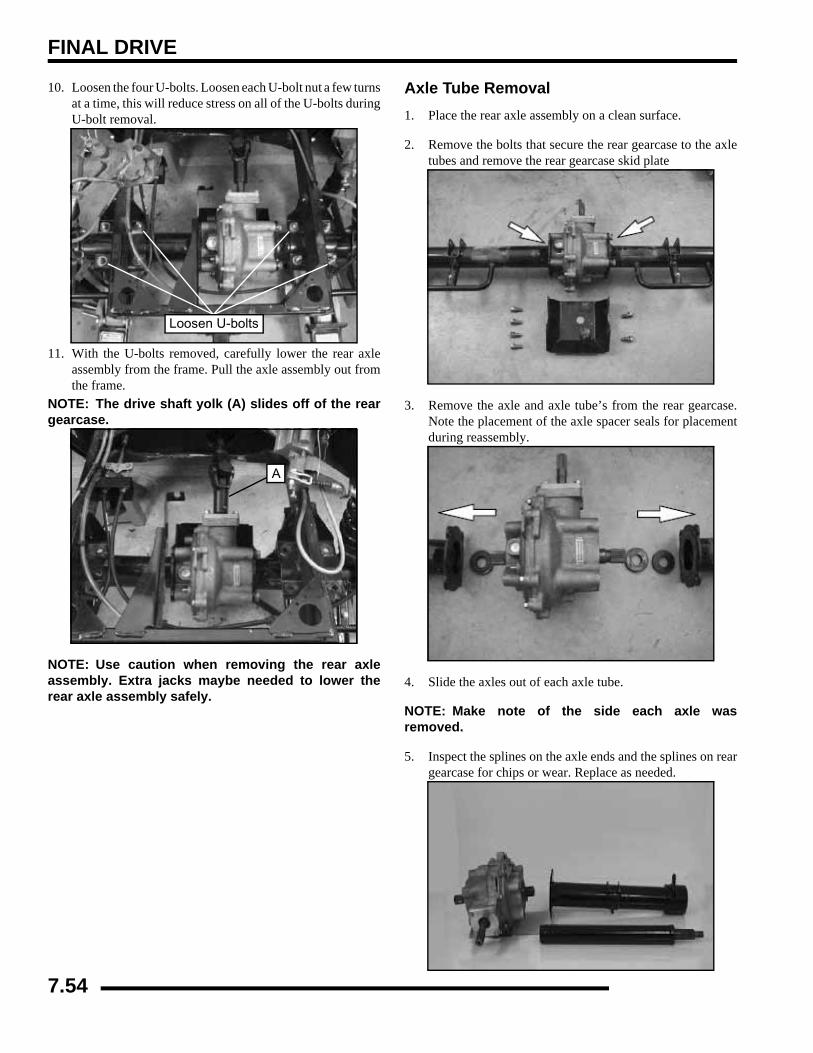
FINAL DRIVE
10. Loosen the four U-bolts. Loosen each U-bolt nut a few turnsat a time, this will reduce stress on all of the U-bolts duringU-bolt removal.
11. With the U-bolts removed, carefully lower the rear axleassembly from the frame. Pull the axle assembly out fromthe frame.
NOTE: The drive shaft yolk (A) slides off of the reargearcase.
NOTE: Use caution when removing the rear axleassembly. Extra jacks maybe needed to lower therear axle assembly safely.
Axle Tube Removal1. Place the rear axle assembly on a clean surface.
2. Remove the bolts that secure the rear gearcase to the axletubes and remove the rear gearcase skid plate
3. Remove the axle and axle tube’s from the rear gearcase.Note the placement of the axle spacer seals for placementduring reassembly.
4. Slide the axles out of each axle tube.
NOTE: Make note of the side each axle wasremoved.
5. Inspect the splines on the axle ends and the splines on reargearcase for chips or wear. Replace as needed.
Loosen U-bolts
A
7.54
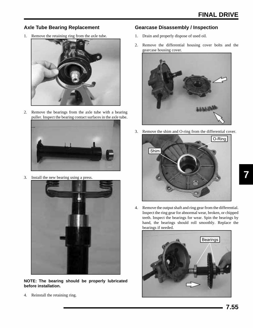
FINAL DRIVE
7
Axle Tube Bearing Replacement1. Remove the retaining ring from the axle tube.
2. Remove the bearings from the axle tube with a bearingpuller. Inspect the bearing contact surfaces in the axle tube.
3. Install the new bearing using a press.
NOTE: The bearing should be properly lubricatedbefore installation.
4. Reinstall the retaining ring.
Gearcase Disassembly / Inspection1. Drain and properly dispose of used oil.
2. Remove the differential housing cover bolts and thegearcase housing cover.
3. Remove the shim and O-ring from the differential cover.
4. Remove the output shaft and ring gear from the differential.Inspect the ring gear for abnormal wear, broken, or chippedteeth. Inspect the bearings for wear. Spin the bearings byhand, the bearings should roll smoothly. Replace thebearings if needed.
Shim
O-Ring
Bearings
7.55

FINAL DRIVE
5. Remove the wave spring from the differential assembly.
6. Remove the four bolts that secure the pinion gear cover tothe differential. Remove the pinion gear cover and O-ring.
7. Remove the pinion shaft from the differential. Inspect forabnormal wear, broken, or chipped teeth.
8. Inspect the pinion shaft bushing for wear.
Gearcase Assembly1. Replace all O-rings, seals, and worn components.
2. Install the pinion shaft into the differential housing.
Wave Spring
4 Bolts
O-Ring
Pinion Gear Cover
7.56
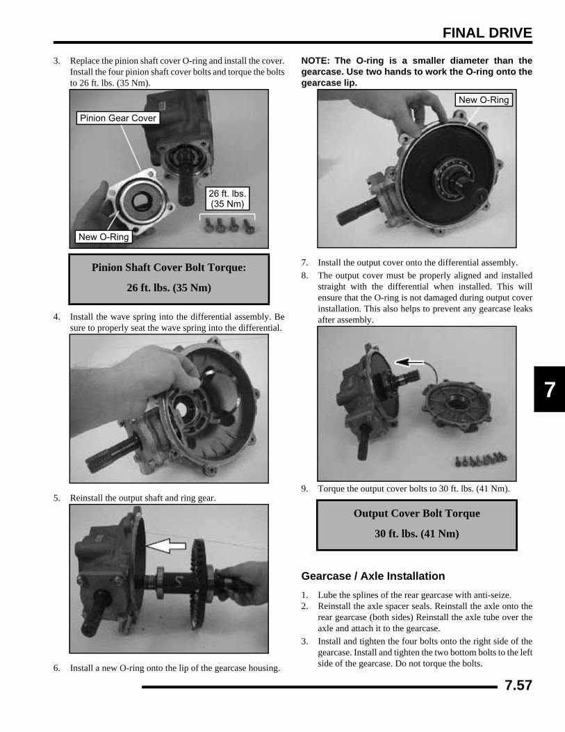
FINAL DRIVE
7
3. Replace the pinion shaft cover O-ring and install the cover.Install the four pinion shaft cover bolts and torque the boltsto 26 ft. lbs. (35 Nm).
4. Install the wave spring into the differential assembly. Besure to properly seat the wave spring into the differential.
5. Reinstall the output shaft and ring gear.
6. Install a new O-ring onto the lip of the gearcase housing.
NOTE: The O-ring is a smaller diameter than thegearcase. Use two hands to work the O-ring onto thegearcase lip.
7. Install the output cover onto the differential assembly.8. The output cover must be properly aligned and installed
straight with the differential when installed. This willensure that the O-ring is not damaged during output coverinstallation. This also helps to prevent any gearcase leaksafter assembly.
9. Torque the output cover bolts to 30 ft. lbs. (41 Nm).
Gearcase / Axle Installation1. Lube the splines of the rear gearcase with anti-seize.2. Reinstall the axle spacer seals. Reinstall the axle onto the
rear gearcase (both sides) Reinstall the axle tube over theaxle and attach it to the gearcase.
3. Install and tighten the four bolts onto the right side of thegearcase. Install and tighten the two bottom bolts to the leftside of the gearcase. Do not torque the bolts.
Pinion Shaft Cover Bolt Torque:
26 ft. lbs. (35 Nm)
26 ft. lbs.
New O-Ring
Pinion Gear Cover
(35 Nm)
Output Cover Bolt Torque
30 ft. lbs. (41 Nm)
New O-Ring
7.57

FINAL DRIVE
NOTE: The two top gearcase / axle tube bolts (B) onthe left side are installed into the frame later in thisassembly procedure.
4. Fit the rear axle assembly up to the frame. Slide the reardriveshaft yoke (A) onto the rear gearcase input shaft.
5. Fit the rear axle assembly up to frame. Attach the rear axleassembly to the shocks. Leave the shock bolts finger tightuntil assembly is complete.
NOTE: Use a jack or another person to assist withthe rear axle assembly installation.
NOTE: Use caution when removing the rear axleassembly. Extra jacks maybe needed to raise therear axle assembly safely.
6. Install the four U-bolts. Align the U-bolts with the whitemarks previously made on the axle tube for proper rear axlealignment.
NOTE: Use a floor jack to help align the rear axleassembly for the U-bolt installation.
7. Install the U-bolt nuts, but do not tighten the nuts.
8. Install the two frame to gearcase bolts (B). Torque thegearcase bolts on both sides of the gearcase to 60 ft. lbs.(81 Nm).
4 Bolts2 Bolts
B
B
A
Axle Tube to Gear Case Bolt Torque:60 ft. lbs. (81 Nm)
U-bolt Alignment Marks
B
7.58
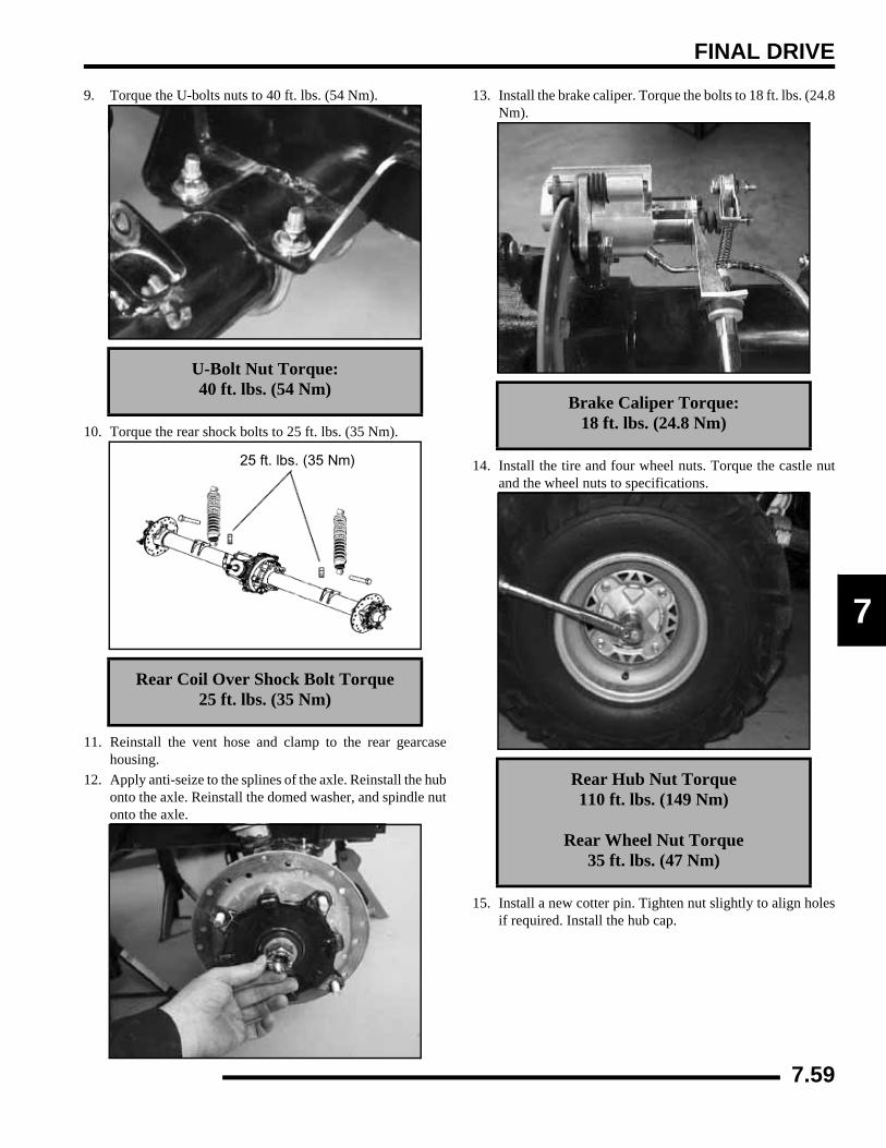
FINAL DRIVE
7
9. Torque the U-bolts nuts to 40 ft. lbs. (54 Nm).
10. Torque the rear shock bolts to 25 ft. lbs. (35 Nm).
11. Reinstall the vent hose and clamp to the rear gearcasehousing.
12. Apply anti-seize to the splines of the axle. Reinstall the hubonto the axle. Reinstall the domed washer, and spindle nutonto the axle.
13. Install the brake caliper. Torque the bolts to 18 ft. lbs. (24.8Nm).
14. Install the tire and four wheel nuts. Torque the castle nutand the wheel nuts to specifications.
15. Install a new cotter pin. Tighten nut slightly to align holesif required. Install the hub cap.
U-Bolt Nut Torque:40 ft. lbs. (54 Nm)
Rear Coil Over Shock Bolt Torque25 ft. lbs. (35 Nm)
25 ft. lbs. (35 Nm)
Brake Caliper Torque:18 ft. lbs. (24.8 Nm)
Rear Hub Nut Torque110 ft. lbs. (149 Nm)
Rear Wheel Nut Torque35 ft. lbs. (47 Nm)
7.59
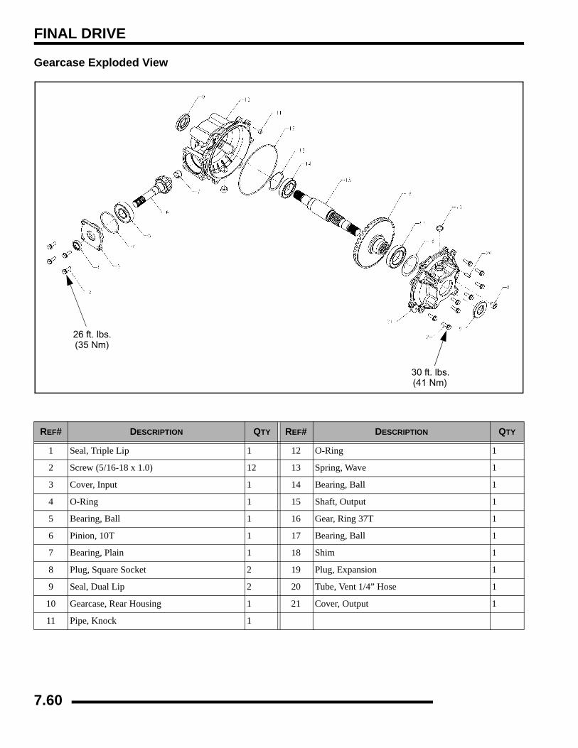
FINAL DRIVE
Gearcase Exploded View
REF# DESCRIPTION QTY REF# DESCRIPTION QTY
1 Seal, Triple Lip 1 12 O-Ring 1
2 Screw (5/16-18 x 1.0) 12 13 Spring, Wave 1
3 Cover, Input 1 14 Bearing, Ball 1
4 O-Ring 1 15 Shaft, Output 1
5 Bearing, Ball 1 16 Gear, Ring 37T 1
6 Pinion, 10T 1 17 Bearing, Ball 1
7 Bearing, Plain 1 18 Shim 1
8 Plug, Square Socket 2 19 Plug, Expansion 1
9 Seal, Dual Lip 2 20 Tube, Vent 1/4” Hose 1
10 Gearcase, Rear Housing 1 21 Cover, Output 1
11 Pipe, Knock 1
26 ft. lbs.(35 Nm)
30 ft. lbs.(41 Nm)
7.60
TRANSMISSION
CHAPTER 8TRANSMISSION
8
TORQUE SPECIFICATIONS. . . . . . . . . . . . . . . . . . . . . . . . . . . . . . . . . . . . . . . . . . . . . . . 8.2SHIFT LEVER . . . . . . . . . . . . . . . . . . . . . . . . . . . . . . . . . . . . . . . . . . . . . . . . . . . . . . . . . . 8.2
REMOVAL . . . . . . . . . . . . . . . . . . . . . . . . . . . . . . . . . . . . . . . . . . . . . . . . . . . . . . . . . . . . 8.2INSTALLATION . . . . . . . . . . . . . . . . . . . . . . . . . . . . . . . . . . . . . . . . . . . . . . . . . . . . . . . . 8.2
SHIFT LINKAGE . . . . . . . . . . . . . . . . . . . . . . . . . . . . . . . . . . . . . . . . . . . . . . . . . . . . . . . . 8.2INSPECTION . . . . . . . . . . . . . . . . . . . . . . . . . . . . . . . . . . . . . . . . . . . . . . . . . . . . . . . . . . 8.2ADJUSTMENT . . . . . . . . . . . . . . . . . . . . . . . . . . . . . . . . . . . . . . . . . . . . . . . . . . . . . . . . . 8.3
TRANSMISSION SERVICE. . . . . . . . . . . . . . . . . . . . . . . . . . . . . . . . . . . . . . . . . . . . . . . . 8.3TRANSMISSION REMOVAL . . . . . . . . . . . . . . . . . . . . . . . . . . . . . . . . . . . . . . . . . . . . . . 8.3TRANSMISSION DISASSEMBLY . . . . . . . . . . . . . . . . . . . . . . . . . . . . . . . . . . . . . . . . . . 8.5TRANSMISSION ASSEMBLY . . . . . . . . . . . . . . . . . . . . . . . . . . . . . . . . . . . . . . . . . . . . 8.10TRANSMISSION INSTALLATION . . . . . . . . . . . . . . . . . . . . . . . . . . . . . . . . . . . . . . . . . 8.14
TROUBLESHOOTING. . . . . . . . . . . . . . . . . . . . . . . . . . . . . . . . . . . . . . . . . . . . . . . . . . . 8.15TROUBLESHOOTING CHECKLIST. . . . . . . . . . . . . . . . . . . . . . . . . . . . . . . . . . . . . . . . 8.15
TRANSMISSION EXPLODED VIEW. . . . . . . . . . . . . . . . . . . . . . . . . . . . . . . . . . . . . . . . 8.16EXPLODED VIEW (4X4, 6X6) . . . . . . . . . . . . . . . . . . . . . . . . . . . . . . . . . . . . . . . . . . . . 8.16
8.1
TRANSMISSION
TORQUE SPECIFICATIONS
SHIFT LEVERRemoval1. Disconnect linkage cable from shifter.
2. Remove one bolt attaching the gear shift selector mount tomachine frame.
3. Remove the shift lever cover and then remove the screw.Pull off the shifter knob.
4. Lift the gear shift selector out of mounting bracket andaway from frame.
Installation1. Repeat the steps in reverse order to install the gear shift
selector.
SHIFT LINKAGEInspectionLinkage rod adjustment is necessary when symptoms include:
• No All Wheel Drive light
• Noise on deceleration
• Inability to engage a gear
• Excessive gear clash (noise)
• Shift selectors moving out of desired range
NOTE: Remove necessary components to gainaccess to shift linkage cable ends (i.e. exhaust heatshield, exhaust pipe, etc.).
1. Inspect shift linkage cable, clevis pins, and pivot bushingsand replace if worn or damaged.
2. Be sure idle speed is adjusted properly.
ITEM TORQUE VALUE
Transmission Fill Plug10-14 ft. lbs.(14-19 Nm)
Transmission Drain Plug10-14 ft. lbs.(14-19 Nm)
Transmission Case Bolts27-34 ft. lbs. (37-46 Nm)
Bell Crank Nut12-18 ft. lbs. (16-24 Nm)
Bell Crank Gear Cover7-9 ft. lbs.
(10-12 Nm)
Transmission Mounting Bolts
25 ft. lbs. (35 Nm)
TransmissionLubricant / Amount
AGL Gearcase Lube 15.2 oz. (450 ml)
Cover
Shifter knob
Bearing
Cable
BoltShifter
Grommet
Screw
Shift Lever Breakdown
Shift Lever Location
Shift Lever
8.2
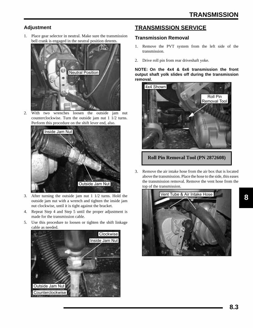
TRANSMISSION
8
Adjustment1. Place gear selector in neutral. Make sure the transmission
bell crank is engaged in the neutral position detents.
2. With two wrenches loosen the outside jam nutcounterclockwise. Turn the outside jam nut 1 1/2 turns.Perform this procedure on the shift lever end, also.
3. After turning the outside jam nut 1 1/2 turns. Hold theoutside jam nut with a wrench and tighten the inside jamnut clockwise, until it is tight against the bracket.
4. Repeat Step 4 and Step 5 until the proper adjustment ismade for the transmission cable.
5. Use this procedure to loosen or tighten the shift linkagecable as needed.
TRANSMISSION SERVICETransmission Removal1. Remove the PVT system from the left side of the
transmission.
2. Drive roll pin from rear driveshaft yoke.
NOTE: On the 4x4 & 6x6 transmission the frontoutput shaft yolk slides off during the transmissionremoval.
3. Remove the air intake hose from the air box that is locatedabove the transmission. Place the hose to the side, this easesthe transmission removal. Remove the vent hose from thetop of the transmission.
Neutral Position
Inside Jam Nut
Outside Jam Nut
Clockwise
Counterclockwise
Inside Jam Nut
Outside Jam Nut
Roll Pin Removal Tool (PN 2872608)
Roll PinRemoval Tool
4x4 Shown
Vent Tube & Air Intake Hose
8.3

TRANSMISSION
4. Disconnect the transmission switch.
5. Remove the cotter pin from the shift linkage rod. Removethe shift linkage rod and a washer from the bellcrank.
6. Loosen the jam nuts for the transmission cable. Remove thecable from the mounting bracket.
7. Remove the mounting bolts from the transmissionmounting on both sides of the transmission.
8. Remove the four bottom transmission to frame bolts.
9. Remove the rear transmission to frame bolt.
10. Remove front transmission-to-engine mount bolt.
11. Remove transmission from right side of frame.
Transmission Switch
Jam Nuts
General Transmission Mounting
8.4
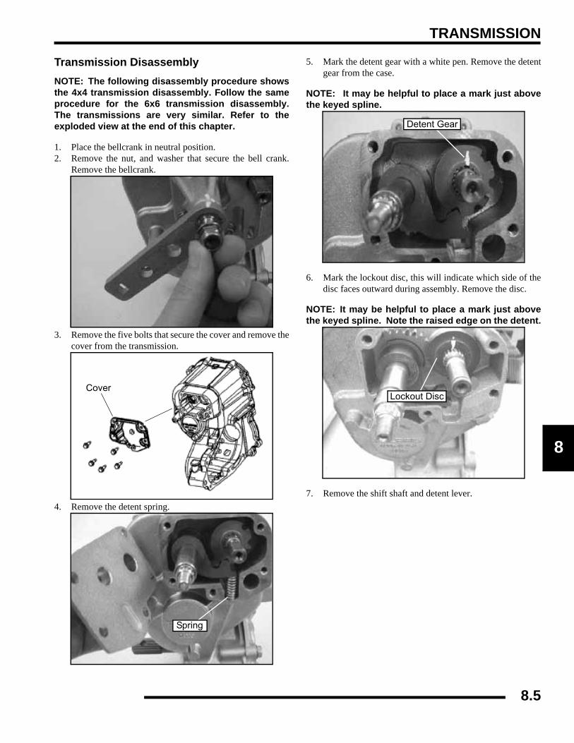
TRANSMISSION
8
Transmission DisassemblyNOTE: The following disassembly procedure showsthe 4x4 transmission disassembly. Follow the sameprocedure for the 6x6 transmission disassembly.The transmissions are very similar. Refer to theexploded view at the end of this chapter.
1. Place the bellcrank in neutral position.2. Remove the nut, and washer that secure the bell crank.
Remove the bellcrank.
3. Remove the five bolts that secure the cover and remove thecover from the transmission.
4. Remove the detent spring.
5. Mark the detent gear with a white pen. Remove the detentgear from the case.
NOTE: It may be helpful to place a mark just abovethe keyed spline.
6. Mark the lockout disc, this will indicate which side of thedisc faces outward during assembly. Remove the disc.
NOTE: It may be helpful to place a mark just abovethe keyed spline. Note the raised edge on the detent.
7. Remove the shift shaft and detent lever.
Cover
Spring
Detent Gear
Lockout Disc
8.5
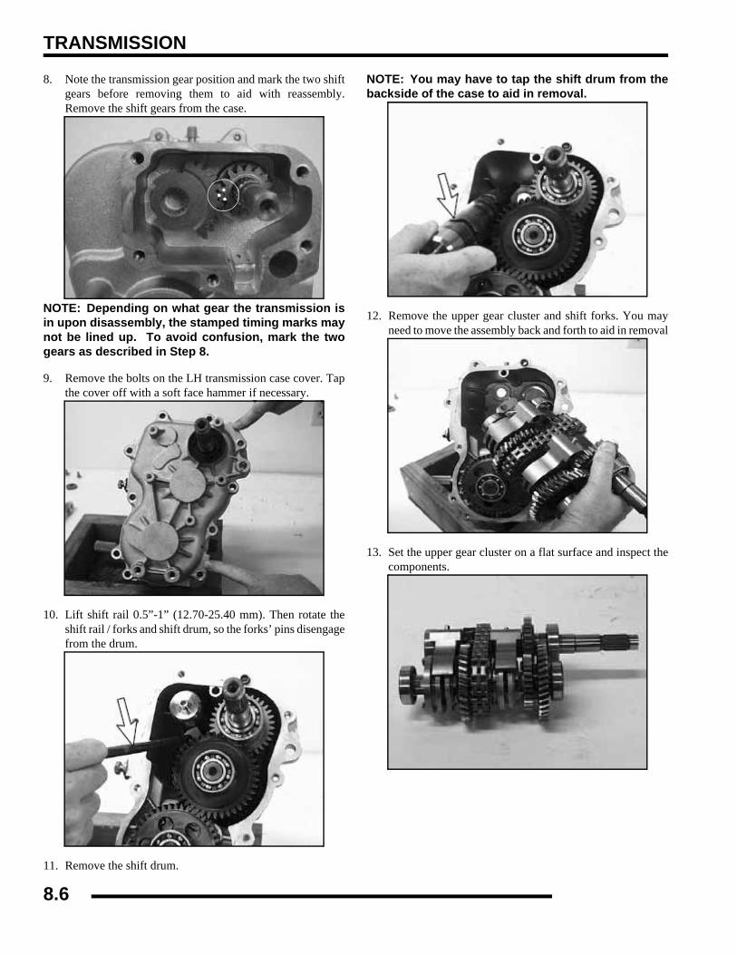
TRANSMISSION
8. Note the transmission gear position and mark the two shiftgears before removing them to aid with reassembly.Remove the shift gears from the case.
NOTE: Depending on what gear the transmission isin upon disassembly, the stamped timing marks maynot be lined up. To avoid confusion, mark the twogears as described in Step 8.
9. Remove the bolts on the LH transmission case cover. Tapthe cover off with a soft face hammer if necessary.
10. Lift shift rail 0.5”-1” (12.70-25.40 mm). Then rotate theshift rail / forks and shift drum, so the forks’ pins disengagefrom the drum.
11. Remove the shift drum.
NOTE: You may have to tap the shift drum from thebackside of the case to aid in removal.
12. Remove the upper gear cluster and shift forks. You mayneed to move the assembly back and forth to aid in removal
13. Set the upper gear cluster on a flat surface and inspect thecomponents.
8.6

TRANSMISSION
8
14. Remove the shift forks from the assembly. Note the correctposition of each fork.
NOTE: The picture above depicts a transmissionwith a “park dog” on the end of the shaft instead of aregular “shift dog”. The transmission will have aregular shift dog in the location indicated by thearrow in the photo.
15. Remove the bearing from the reverse shaft with a puller.
16. Remove the park lock engagement dog. Remove the wavespring and reverse engagement dog.
17. Remove the bearing from the input shaft with a puller.
18. Remove the snap ring and washer from the reverse shaft.
19. Remove low gear (33T) and the needle bearing.
20. Remove the reverse gear shaft.
Shift Fork
EngagementDogs
8.7

TRANSMISSION
21. Remove the rest of the bearings from the shafts.
22. Use a press to remove the gear from the shaft.
23. Make note of the direction of the gear and hub location.
24. Remove the gear, split bearing, and washer from the reverseshaft.
25. Slide off the shift dogs and wave springs.
26. Remove the snap ring, washer, gear, and split bearing.
8.8
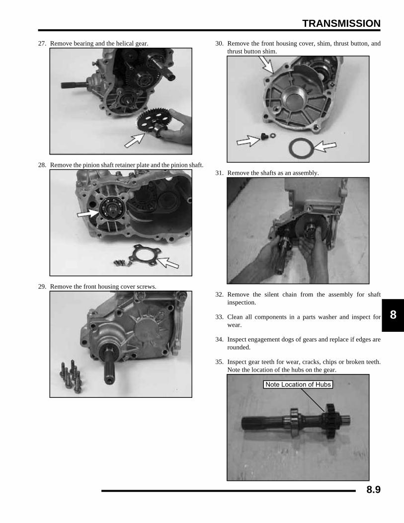
TRANSMISSION
8
27. Remove bearing and the helical gear.
28. Remove the pinion shaft retainer plate and the pinion shaft.
29. Remove the front housing cover screws.
30. Remove the front housing cover, shim, thrust button, andthrust button shim.
31. Remove the shafts as an assembly.
32. Remove the silent chain from the assembly for shaftinspection.
33. Clean all components in a parts washer and inspect forwear.
34. Inspect engagement dogs of gears and replace if edges arerounded.
35. Inspect gear teeth for wear, cracks, chips or broken teeth.Note the location of the hubs on the gear.
Note Location of Hubs
8.9

TRANSMISSION
36. Remove seals from transmission case.
IMPORTANT: New seals should be installed after thetransmission is completely assembled.
37. Inspect bearings for smooth operation. Check for excessiveplay between inner and outer race.
Transmission Assembly1. Reinstall the chain onto the front output shaft and rear
output shaft.
2. Install front and rear output shafts into the case.
3. Before installing the cover make sure the sealing surfacesare clean and dry, and shafts are fully seated in thetransmission case. Apply Polaris Crankcase Sealant to themating surfaces.
4. Reinstall the thrust button shim, thrust button, and othershims into the cover. Reinstall cover and torque bolts in acriss-cross pattern in 3 steps to 27-34 ft. lbs. (37-46 Nm).
NOTE: Make sure that the case locating pins (knockpipes) are in place.
5. Apply grease to the seal lips. Apply electricians tape orsomehow cover the splines of the shaft to protect the seallips during installation. Install new front and rear outputshaft seals.
6. Install pinion shaft with bearing.
7. Install retainer plate with flat side toward bearing.
Crankcase Sealant
(PN 2871557)
Front Cover Bolt Torque:
27-34 ft. lbs. (37-46 Nm)
8.10
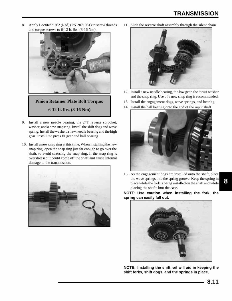
TRANSMISSION
8
8. Apply Loctite™ 262 (Red) (PN 2871951) to screw threadsand torque screws to 6-12 ft. lbs. (8-16 Nm).
9. Install a new needle bearing, the 24T reverse sprocket,washer, and a new snap ring. Install the shift dogs and wavespring. Install the washer, a new needle bearing and the highgear. Install the press fit gear and ball bearing.
10. Install a new snap ring at this time. When installing the newsnap ring, open the snap ring just far enough to go over theshaft, to avoid stressing the snap ring. If the snap ring isoverstressed it could come off the shaft and cause internaldamage to the transmission.
11. Slide the reverse shaft assembly through the silent chain.
12. Install a new needle bearing, the low gear, the thrust washerand the snap ring. Use of a new snap ring is recommended.
13. Install the engagement dogs, wave springs, and bearing.14. Install the ball bearing onto the end of the input shaft.
15. As the engagement dogs are installed onto the shaft, placethe wave springs into the spring groove. Keep the spring inplace while the fork is being installed on the shaft and whileplacing the shafts into the case.
NOTE: Use caution when installing the fork, thespring can easily fall out.
NOTE: Installing the shift rail will aid in keeping theshift forks, shift dogs, and the springs in place.
Pinion Retainer Plate Bolt Torque:
6-12 ft. lbs. (8-16 Nm)
8.11
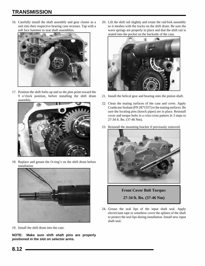
TRANSMISSION
16. Carefully install the shaft assembly and gear cluster as aunit into their respective bearing case recesses. Tap with asoft face hammer to seat shaft assemblies.
17. Position the shift forks up and so the pins point toward the9 o’clock position, before installing the shift drumassembly.
18. Replace and grease the O-ring’s on the shift drum beforeinstallation.
19. Install the shift drum into the case.
NOTE: Make sure shift shaft pins are properlypositioned in the slot on selector arms.
20. Lift the shift rail slightly and rotate the rail/fork assemblyso it meshes with the tracks on the shift drum. Be sure thewave springs are properly in place and that the shift rail isseated into the pocket on the backside of the case.
21. Install the helical gear and bearing onto the pinion shaft.
22. Clean the mating surfaces of the case and cover. ApplyCrankcase Sealant (PN 2871557) to the mating surfaces. Besure the locating pins (knock pipes) are in place. Reinstallcover and torque bolts in a criss-cross pattern in 3 steps to27-34 ft. lbs. (37-46 Nm).
23. Reinstall the mounting bracket if previously removed.
24. Grease the seal lips of the input shaft seal. Applyelectricians tape or somehow cover the splines of the shaftto protect the seal lips during installation. Install new inputshaft seal.
Front Cover Bolt Torque:
27-34 ft. lbs. (37-46 Nm)
8.12
TRANSMISSION
8
25. Install drain plug with a new sealing washer. Torque drainplug to 10-14 ft. lbs. (14-19 Nm).
26. Place a small amount of grease (PN 2871551) into thepocket before installing the sector gear. Install the shift gear(16T) on the shift drum shaft. Install the sector gear in thebushing pocket on the left side. Align the timing marks youmade on the gears during disassembly.
IMPORTANT: Note the location of the skip tooth onthe splines. Apply a light coating of grease on thegear teeth.
27. Install the shift shaft along with the detent lever.
28. Install the lockout disc with the raised edge facing outward.Use the white mars that was previously applied forreference.
29. Install the detent gear with the raised edge facing outward.Note the keyed spline on the end of the shaft.
30. Install the detent lever spring. Install a new o-ring onto theshift shaft after the detent lever is assembled to the shaft.Place a small amount of grease on the small O-ring on theshift shaft and on the detent gear. Grease the o-ring on theend of the shift drum.
31. Install the cover and hand tighten all of the bolts. Tightenthe bolt indicated in the picture below first and torque thebolt to 7-9 ft. lbs. (10-12 Nm). This helps to align the coverand shaft to ensure smoother shifting.
Drain Plug Torque:
10-14 ft. lbs. (14-19 Nm)
Transmission
Drain Plug10-14 ft. lbs.(14-19 Nm)
Lockout Disc
Spring
Detent Gear
Detent Lever
7-9 ft. lbs.
Tighten This Bolt First
(10-12 Nm)
8.13
TRANSMISSION
32. Torque the remaining bolts to 7-9 ft.lbs. (10-12 Nm).
33. Install a new bellcrank onto the shift shaft. Note the keyedspline on the bellcrank and shaft. Install the washer and nut.Torque the bellcrank nut to 12-18 ft. lbs. (16-24 Nm).
34. Install transmission and add Polaris AGL GearcaseLubricant (PN 2872602).
Transmission Installation1. Install transmission from right side of vehicle.
2. Position transmission in frame.
3. Loosely install the front transmission to frame bolts.
4. Loosely install the rear transmission to frame bolt.
5. Loosely install the three bottom transmission to framebolts.
6. Tighten mounting fasteners in order A-D as shown.
NOTE: Be sure to tighten the lower transmissionbolts first, this ensures that the transmission is tightagainst the lower frame and helps to properly alignthe transmission.
NOTE: Align clutches as outlined in Chapter 6.
7. Align the front input shaft to the front propshaft yoke onthe vehicle.
8. Align rear output shaft to rear propshaft yoke and roll pinhole.
9. Slide rear output shaft and into propshaft yoke. Drive theroll pin into the driveshaft yolk.
10. Reinstall the shift linkage rod, the air intake hose, and thevent hose on top of the transmission.
Cover Bolt Torque:
7-9 ft. lbs. (10-12 Nm)
Bellcrank Nut Torque:
12-18 ft. lbs. (16-24 Nm)
=
AGL Gearcase Lube15.2 oz. (450 ml)
Keyed Spline
Transmission Mounting Bolts Torque
25 ft. lbs. (34.5 Nm)
8.14
TRANSMISSION
8
TROUBLESHOOTINGTroubleshooting ChecklistCheck the following items when shifting difficulty is encountered.
• Idle speed adjustment
• PVT alignment
• Transmission oil type/quality
• Transmission torque stop adjustment (where applicable)
• Engine torque stop adjustment (where applicable)
• Drive belt deflection
• Loose fasteners on rod ends
• Loose fasteners on selector box
• Worn rod ends, clevis pins, or pivot arm bushings
• Linkage rod adjustment and rod end positioning
• Shift selector rail travel
• *Worn, broken or damaged internal transmission components
NOTE: To determine if shifting difficulty or problem is caused by an internal transmission problem, isolatethe transmission by disconnecting linkage rod from transmission bellcrank. Manually select each gear rangeat the transmission bellcrank, and test ride vehicle. If it functions properly, the problem is outside thetransmission.
If transmission problem remains, disassemble transmission and inspect all gear dogs for wear (rounding),damage. Inspect all bearings, circlips, thrust washers and shafts for wear.
8.15

TRANSMISSION
TRANSMISSION EXPLODED VIEWExploded View (4x4, 6x6)
FOR REASSEMBLY
Apply White LithiumBased Grease.
Apply PolarisCrankcase Sealant.
Apply LoctiteTM 262 tothe bolt threads.
12-18 ft. lbs.(16-24 Nm)
7-9 ft. lbs.(10-12 Nm)
15-19 ft. lbs.(20-26 Nm)
27-34 ft. lbs.(37-46 Nm)
6-12 ft. lbs.(8-16 Nm)
GREASE
27-34 ft. lbs.(37-46 Nm)
10-14 ft. lbs.(14-19 Nm)
8.16
TRANSMISSION
8
Exploded View (4x4, 6x6), Cont.
Ref. Qty. Description Ref. Qty. Description1 Asm., 4x4 Transmission 35. 1 22T Sprocket
1. 1 Nut 36. 1 19T Sprocket2. 1 Shift Drum Bellcrank 37. 1 Silent Chain3. 5 Cover Screws 38. 1 Front Main Output Shaft4. 1 Sector Cover 39. 1 Gear Set - 10T / 31T6. 1 O-ring 40. 1 Ball Bearing7. 1 Detent Pawl 41. 1 Spacer8. 1 Compression Spring 42. 1 Retaining Ring9. 1 Shift Shaft 43. 1 Bearing Center Drive Cover10. 1 31T Sector Gear 44. 4 Torx Screws11. 2 Hollow Hex Plug 45. 1 56T Mid Output Helical Gear (6x6: 60T Gear)12. 2 Triple Lip Seal 46. 4 Ball Bearing13. 1 Gearcase, Main 47. 1 Reverse Shaft14. 1 Vent Tube 48. 1 Needle Cage Bearing15. 1 O-Ring 49. 1 24T 6 Face Sprocket16. 1 Shift Drum 50. 1 Washer17. 1 External Retaining Ring 51. 2 External Retaining Ring18. 1 6-Pin Switch 52. 4 6 Face Engagement Dog19. 1 O-ring 53. 2 Wave Spring20. 1 Detent Star 54. 1 Washer21. 1 Lockout Disc 55. 2 Needle Cage Bearing22. 1 16T Sector Gear 56. 1 28T 6 Face Gear (6x6: 23T Gear)23. 2 Lock Nut 57. 1 51T Mid Output Helical Gear (6x6: 47T Gear)24. 4 Dowel Pin 58. 1 Shift Shaft Rail25. 4 Ball Bearing 59. 2 Shift Fork w/Pin26. 1 Thrust Washer 61. 1 Silent Chain27. 1 Vent Plug Cap 62. 1 Input Shaft Assy.28. 1 Output Shaft 63. 1 LH Main Cover29. 1 Shim 64. 1 Dual Lip Seal30. 1 Thrust Button 65. 1 Transmission Mount Bracket31. 1 Shim 66. 2 Hex Screw32. 1 Output Cover 67. 1 33T 6 Face Gear33. 15 Screw 68. 1 Washer34. 1 Plain Bearing 69. 1 Label
8.17
BRAKES
CHAPTER 9BRAKES
9
GENERAL SPECIFICATIONS / TORQUE SPECIFICATIONS / SPECIAL TOOLS . . . . . 9.2BRAKE SYSTEM SERVICE NOTES. . . . . . . . . . . . . . . . . . . . . . . . . . . . . . . . . . . . . . . . . 9.3BRAKE NOISE TROUBLESHOOTING . . . . . . . . . . . . . . . . . . . . . . . . . . . . . . . . . . . . . . . 9.3HYDRAULIC BRAKE SYSTEM OPERATION. . . . . . . . . . . . . . . . . . . . . . . . . . . . . . . . . . 9.4BRAKE SYSTEM EXPLODED VIEW . . . . . . . . . . . . . . . . . . . . . . . . . . . . . . . . . . . . . . . . 9.5MASTER CYLINDER. . . . . . . . . . . . . . . . . . . . . . . . . . . . . . . . . . . . . . . . . . . . . . . . . . . . . 9.6
REMOVAL / INSTALLATION . . . . . . . . . . . . . . . . . . . . . . . . . . . . . . . . . . . . . . . . . . . . . . 9.6FOOT BRAKE PEDAL. . . . . . . . . . . . . . . . . . . . . . . . . . . . . . . . . . . . . . . . . . . . . . . . . . . . 9.6
PEDAL REMOVAL / INSTALLATION. . . . . . . . . . . . . . . . . . . . . . . . . . . . . . . . . . . . . . . . 9.6BRAKE BLEEDING / FLUID CHANGE . . . . . . . . . . . . . . . . . . . . . . . . . . . . . . . . . . . . . . . 9.7PARKING BRAKE . . . . . . . . . . . . . . . . . . . . . . . . . . . . . . . . . . . . . . . . . . . . . . . . . . . . . . . 9.8
EXPLODED VIEW . . . . . . . . . . . . . . . . . . . . . . . . . . . . . . . . . . . . . . . . . . . . . . . . . . . . . . 9.8INSPECTION / ADJUSTMENT. . . . . . . . . . . . . . . . . . . . . . . . . . . . . . . . . . . . . . . . . . . . . 9.9
PARKING BRAKE CALIPER SERVICE . . . . . . . . . . . . . . . . . . . . . . . . . . . . . . . . . . . . . 9.10EXPLODED VIEW . . . . . . . . . . . . . . . . . . . . . . . . . . . . . . . . . . . . . . . . . . . . . . . . . . . . . 9.10CALIPER REMOVAL . . . . . . . . . . . . . . . . . . . . . . . . . . . . . . . . . . . . . . . . . . . . . . . . . . . 9.10CALIPER DISASSEMBLY / INSPECTION . . . . . . . . . . . . . . . . . . . . . . . . . . . . . . . . . . . 9.11NEW BRAKE PAD INSTALLATION . . . . . . . . . . . . . . . . . . . . . . . . . . . . . . . . . . . . . . . . 9.12CALIPER INSTALLATION . . . . . . . . . . . . . . . . . . . . . . . . . . . . . . . . . . . . . . . . . . . . . . . 9.12
PARKING BRAKE DISC SERVICE . . . . . . . . . . . . . . . . . . . . . . . . . . . . . . . . . . . . . . . . . 9.12DISC REMOVAL / INSPECTION . . . . . . . . . . . . . . . . . . . . . . . . . . . . . . . . . . . . . . . . . . 9.12
FRONT BRAKE PADS. . . . . . . . . . . . . . . . . . . . . . . . . . . . . . . . . . . . . . . . . . . . . . . . . . . 9.13PAD REMOVAL / DISASSEMBLY / INSPECTION. . . . . . . . . . . . . . . . . . . . . . . . . . . . . 9.13PAD ASSEMBLY / INSTALLATION / ADJUSTMENT . . . . . . . . . . . . . . . . . . . . . . . . . . 9.14
FRONT CALIPER . . . . . . . . . . . . . . . . . . . . . . . . . . . . . . . . . . . . . . . . . . . . . . . . . . . . . . 9.15FRONT CALIPER EXPLODED VIEW . . . . . . . . . . . . . . . . . . . . . . . . . . . . . . . . . . . . . . 9.15CALIPER REMOVAL / DISASSEMBLY . . . . . . . . . . . . . . . . . . . . . . . . . . . . . . . . . . . . . 9.15CALIPER INSPECTION / ASSEMBLY . . . . . . . . . . . . . . . . . . . . . . . . . . . . . . . . . . . . . . 9.16CALIPER INSTALLATION . . . . . . . . . . . . . . . . . . . . . . . . . . . . . . . . . . . . . . . . . . . . . . . 9.17
FRONT BRAKE DISC . . . . . . . . . . . . . . . . . . . . . . . . . . . . . . . . . . . . . . . . . . . . . . . . . . . 9.18DISC INSPECTION / REMOVAL / REPLACEMENT . . . . . . . . . . . . . . . . . . . . . . . . . . . 9.18
REAR BRAKE PAD (4X4) . . . . . . . . . . . . . . . . . . . . . . . . . . . . . . . . . . . . . . . . . . . . . . . . 9.18PAD REMOVAL . . . . . . . . . . . . . . . . . . . . . . . . . . . . . . . . . . . . . . . . . . . . . . . . . . . . . . . 9.18PAD INSPECTION / INSTALLATION. . . . . . . . . . . . . . . . . . . . . . . . . . . . . . . . . . . . . . . 9.19
REAR BRAKE PAD (6X6) . . . . . . . . . . . . . . . . . . . . . . . . . . . . . . . . . . . . . . . . . . . . . . . . 9.20PAD REMOVAL . . . . . . . . . . . . . . . . . . . . . . . . . . . . . . . . . . . . . . . . . . . . . . . . . . . . . . . 9.20PAD INSPECTION / INSTALLATION. . . . . . . . . . . . . . . . . . . . . . . . . . . . . . . . . . . . . . . 9.21
REAR CALIPER. . . . . . . . . . . . . . . . . . . . . . . . . . . . . . . . . . . . . . . . . . . . . . . . . . . . . . . . 9.22REAR CALIPER EXPLODED VIEW. . . . . . . . . . . . . . . . . . . . . . . . . . . . . . . . . . . . . . . . 9.22CALIPER REMOVAL (4X4) . . . . . . . . . . . . . . . . . . . . . . . . . . . . . . . . . . . . . . . . . . . . . . 9.22CALIPER REMOVAL (6X6) . . . . . . . . . . . . . . . . . . . . . . . . . . . . . . . . . . . . . . . . . . . . . . 9.23CALIPER DISASSEMBLY . . . . . . . . . . . . . . . . . . . . . . . . . . . . . . . . . . . . . . . . . . . . . . . 9.23CALIPER INSPECTION / ASSEMBLY . . . . . . . . . . . . . . . . . . . . . . . . . . . . . . . . . . . . . . 9.24CALIPER INSTALLATION (4X4, 6X6) . . . . . . . . . . . . . . . . . . . . . . . . . . . . . . . . . . . . . . 9.25
REAR BRAKE DISC . . . . . . . . . . . . . . . . . . . . . . . . . . . . . . . . . . . . . . . . . . . . . . . . . . . . 9.25TROUBLESHOOTING. . . . . . . . . . . . . . . . . . . . . . . . . . . . . . . . . . . . . . . . . . . . . . . . . . . 9.26
BRAKES SQUEAL / POOR BRAKE PERFORMANCE . . . . . . . . . . . . . . . . . . . . . . . . . 9.26PEDAL VIBRATION . . . . . . . . . . . . . . . . . . . . . . . . . . . . . . . . . . . . . . . . . . . . . . . . . . . . 9.26CALIPER OVERHEATS (BRAKES DRAG) . . . . . . . . . . . . . . . . . . . . . . . . . . . . . . . . . . 9.26BRAKES LOCK. . . . . . . . . . . . . . . . . . . . . . . . . . . . . . . . . . . . . . . . . . . . . . . . . . . . . . . . 9.26
9.1
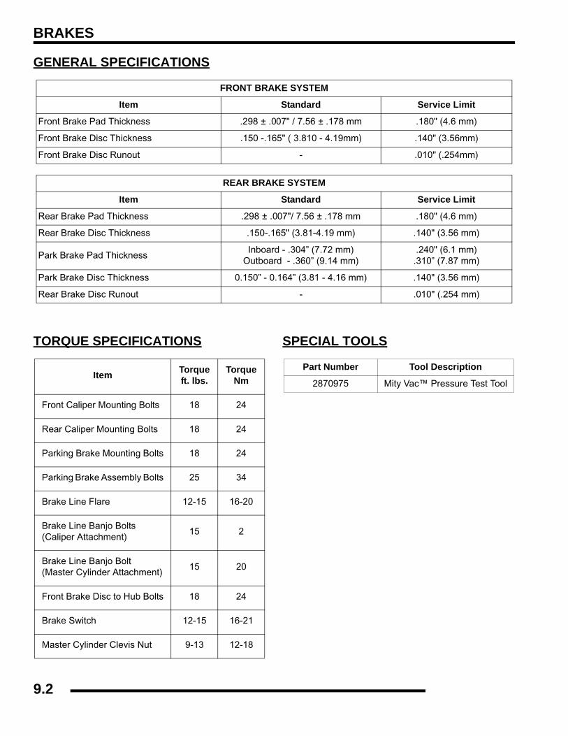
BRAKES
GENERAL SPECIFICATIONS
TORQUE SPECIFICATIONS SPECIAL TOOLS
FRONT BRAKE SYSTEM
Item Standard Service Limit
Front Brake Pad Thickness .298 ± .007" / 7.56 ± .178 mm .180" (4.6 mm)
Front Brake Disc Thickness .150 -.165" ( 3.810 - 4.19mm) .140" (3.56mm)
Front Brake Disc Runout - .010" (.254mm)
REAR BRAKE SYSTEM
Item Standard Service Limit
Rear Brake Pad Thickness .298 ± .007"/ 7.56 ± .178 mm .180" (4.6 mm)
Rear Brake Disc Thickness .150-.165" (3.81-4.19 mm) .140" (3.56 mm)
Park Brake Pad ThicknessInboard - .304” (7.72 mm)
Outboard - .360” (9.14 mm).240" (6.1 mm).310” (7.87 mm)
Park Brake Disc Thickness 0.150” - 0.164” (3.81 - 4.16 mm) .140" (3.56 mm)
Rear Brake Disc Runout - .010" (.254 mm)
Item Torqueft. lbs.
TorqueNm
Front Caliper Mounting Bolts 18 24
Rear Caliper Mounting Bolts 18 24
Parking Brake Mounting Bolts 18 24
Parking Brake Assembly Bolts 25 34
Brake Line Flare 12-15 16-20
Brake Line Banjo Bolts(Caliper Attachment)
15 2
Brake Line Banjo Bolt(Master Cylinder Attachment)
15 20
Front Brake Disc to Hub Bolts 18 24
Brake Switch 12-15 16-21
Master Cylinder Clevis Nut 9-13 12-18
Part Number Tool Description
2870975 Mity Vac™ Pressure Test Tool
9.2
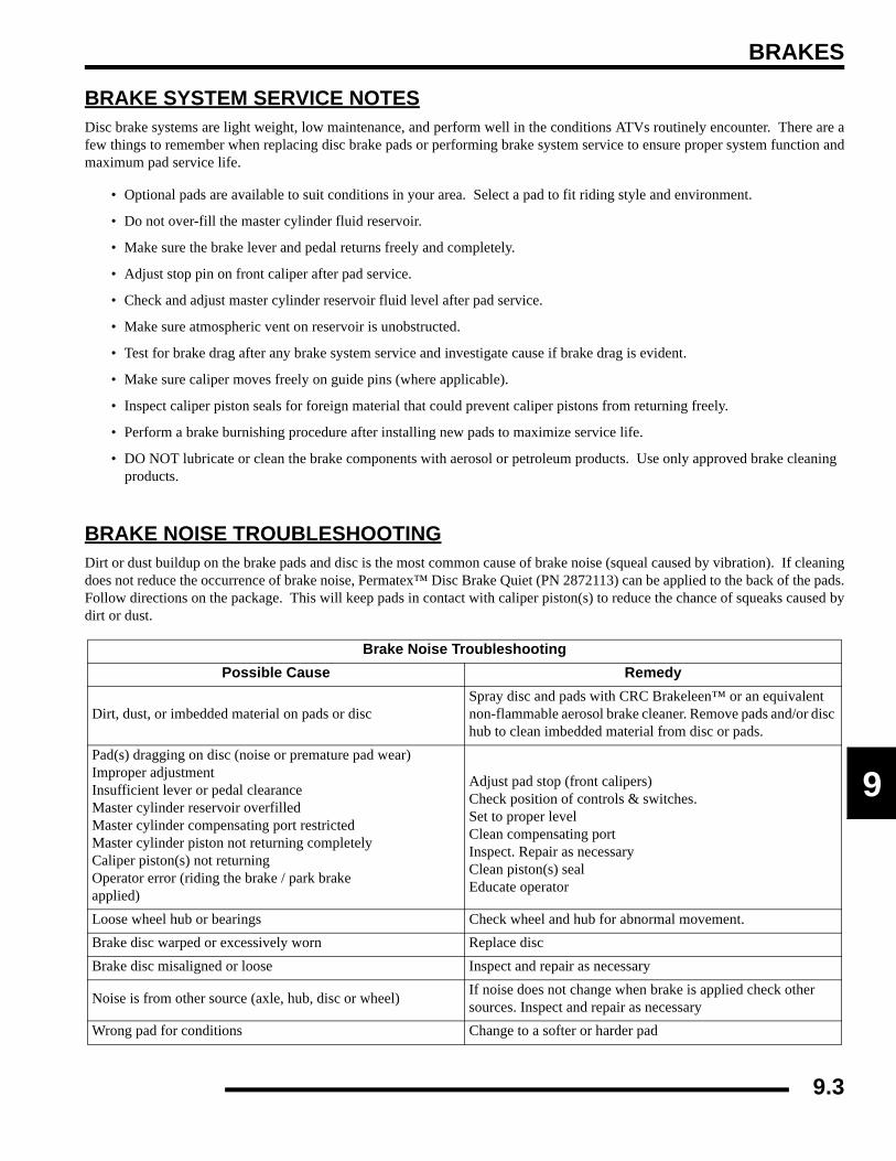
BRAKES
9
BRAKE SYSTEM SERVICE NOTESDisc brake systems are light weight, low maintenance, and perform well in the conditions ATVs routinely encounter. There are afew things to remember when replacing disc brake pads or performing brake system service to ensure proper system function andmaximum pad service life.
• Optional pads are available to suit conditions in your area. Select a pad to fit riding style and environment.
• Do not over-fill the master cylinder fluid reservoir.
• Make sure the brake lever and pedal returns freely and completely.
• Adjust stop pin on front caliper after pad service.
• Check and adjust master cylinder reservoir fluid level after pad service.
• Make sure atmospheric vent on reservoir is unobstructed.
• Test for brake drag after any brake system service and investigate cause if brake drag is evident.
• Make sure caliper moves freely on guide pins (where applicable).
• Inspect caliper piston seals for foreign material that could prevent caliper pistons from returning freely.
• Perform a brake burnishing procedure after installing new pads to maximize service life.
• DO NOT lubricate or clean the brake components with aerosol or petroleum products. Use only approved brake cleaning products.
BRAKE NOISE TROUBLESHOOTINGDirt or dust buildup on the brake pads and disc is the most common cause of brake noise (squeal caused by vibration). If cleaningdoes not reduce the occurrence of brake noise, Permatex™ Disc Brake Quiet (PN 2872113) can be applied to the back of the pads.Follow directions on the package. This will keep pads in contact with caliper piston(s) to reduce the chance of squeaks caused bydirt or dust.
Brake Noise TroubleshootingPossible Cause Remedy
Dirt, dust, or imbedded material on pads or discSpray disc and pads with CRC Brakeleen™ or an equivalent non-flammable aerosol brake cleaner. Remove pads and/or disc hub to clean imbedded material from disc or pads.
Pad(s) dragging on disc (noise or premature pad wear)Improper adjustmentInsufficient lever or pedal clearanceMaster cylinder reservoir overfilledMaster cylinder compensating port restrictedMaster cylinder piston not returning completelyCaliper piston(s) not returningOperator error (riding the brake / park brakeapplied)
Adjust pad stop (front calipers)Check position of controls & switches.Set to proper levelClean compensating portInspect. Repair as necessaryClean piston(s) seal Educate operator
Loose wheel hub or bearings Check wheel and hub for abnormal movement.Brake disc warped or excessively worn Replace discBrake disc misaligned or loose Inspect and repair as necessary
Noise is from other source (axle, hub, disc or wheel) If noise does not change when brake is applied check other sources. Inspect and repair as necessary
Wrong pad for conditions Change to a softer or harder pad
9.3
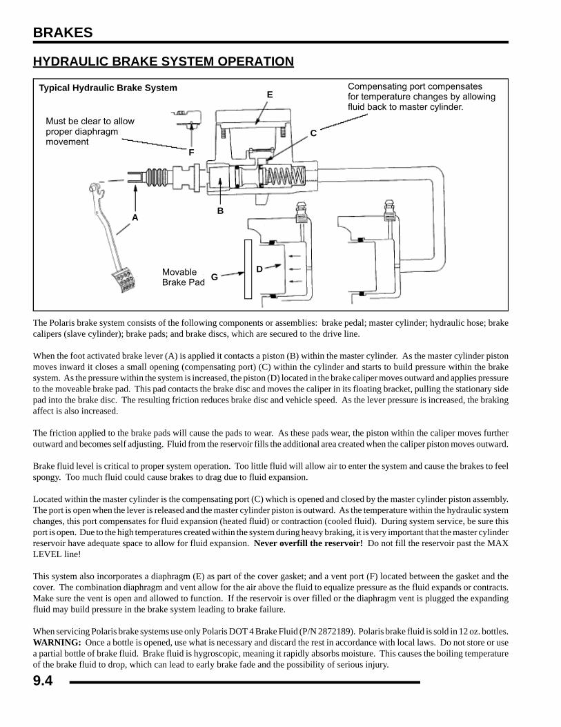
BRAKES
HYDRAULIC BRAKE SYSTEM OPERATION
The Polaris brake system consists of the following components or assemblies: brake pedal; master cylinder; hydraulic hose; brakecalipers (slave cylinder); brake pads; and brake discs, which are secured to the drive line.
When the foot activated brake lever (A) is applied it contacts a piston (B) within the master cylinder. As the master cylinder pistonmoves inward it closes a small opening (compensating port) (C) within the cylinder and starts to build pressure within the brakesystem. As the pressure within the system is increased, the piston (D) located in the brake caliper moves outward and applies pressureto the moveable brake pad. This pad contacts the brake disc and moves the caliper in its floating bracket, pulling the stationary sidepad into the brake disc. The resulting friction reduces brake disc and vehicle speed. As the lever pressure is increased, the brakingaffect is also increased.
The friction applied to the brake pads will cause the pads to wear. As these pads wear, the piston within the caliper moves furtheroutward and becomes self adjusting. Fluid from the reservoir fills the additional area created when the caliper piston moves outward.
Brake fluid level is critical to proper system operation. Too little fluid will allow air to enter the system and cause the brakes to feelspongy. Too much fluid could cause brakes to drag due to fluid expansion.
Located within the master cylinder is the compensating port (C) which is opened and closed by the master cylinder piston assembly.The port is open when the lever is released and the master cylinder piston is outward. As the temperature within the hydraulic systemchanges, this port compensates for fluid expansion (heated fluid) or contraction (cooled fluid). During system service, be sure thisport is open. Due to the high temperatures created within the system during heavy braking, it is very important that the master cylinderreservoir have adequate space to allow for fluid expansion. Never overfill the reservoir! Do not fill the reservoir past the MAXLEVEL line!
This system also incorporates a diaphragm (E) as part of the cover gasket; and a vent port (F) located between the gasket and thecover. The combination diaphragm and vent allow for the air above the fluid to equalize pressure as the fluid expands or contracts.Make sure the vent is open and allowed to function. If the reservoir is over filled or the diaphragm vent is plugged the expandingfluid may build pressure in the brake system leading to brake failure.
When servicing Polaris brake systems use only Polaris DOT 4 Brake Fluid (P/N 2872189). Polaris brake fluid is sold in 12 oz. bottles.WARNING: Once a bottle is opened, use what is necessary and discard the rest in accordance with local laws. Do not store or usea partial bottle of brake fluid. Brake fluid is hygroscopic, meaning it rapidly absorbs moisture. This causes the boiling temperatureof the brake fluid to drop, which can lead to early brake fade and the possibility of serious injury.
Must be clear to allowproper diaphragmmovement
MovableBrake Pad
Compensating port compensatesfor temperature changes by allowingfluid back to master cylinder.
AB
C
D
E
F
G
Typical Hydraulic Brake System
9.4
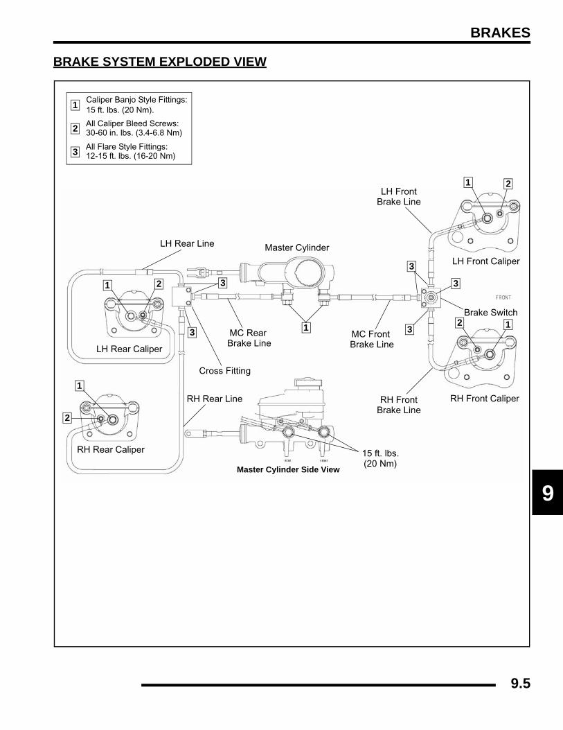
BRAKES
9
BRAKE SYSTEM EXPLODED VIEW
Caliper Banjo Style Fittings:15 ft. lbs. (20 Nm).
All Caliper Bleed Screws:30-60 in. lbs. (3.4-6.8 Nm)
Master Cylinder Side View
Cross Fitting
MC Rear Brake Line
RH Rear Line
RH Rear Caliper
RH FrontBrake Line
RH Front Caliper
Brake Switch
MC Front Brake Line
Master Cylinder
LH Front
LH Rear Caliper
LH Front Caliper
Brake Line
LH Rear Line
1
2
1
1
2
2
1
3 All Flare Style Fittings:12-15 ft. lbs. (16-20 Nm)
3
3 3
3
3
1
12
2
15 ft. lbs.(20 Nm)
9.5
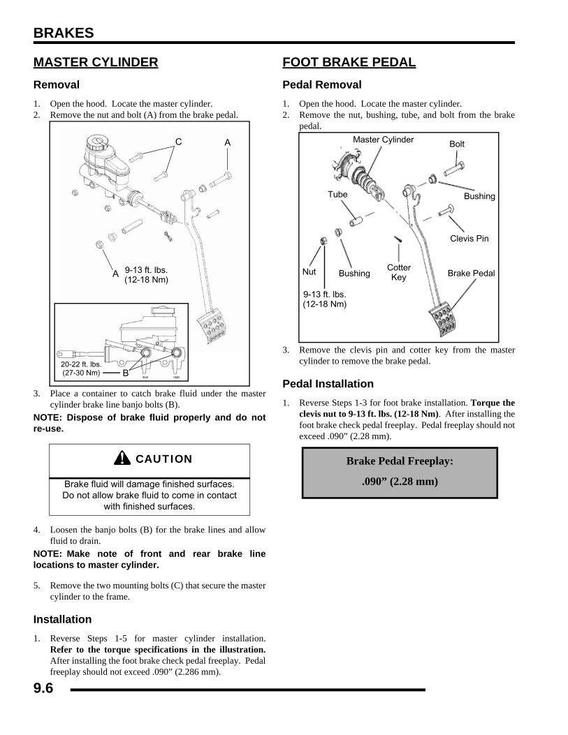
BRAKES
MASTER CYLINDERRemoval1. Open the hood. Locate the master cylinder.2. Remove the nut and bolt (A) from the brake pedal.
3. Place a container to catch brake fluid under the mastercylinder brake line banjo bolts (B).
NOTE: Dispose of brake fluid properly and do notre-use.
4. Loosen the banjo bolts (B) for the brake lines and allowfluid to drain.
NOTE: Make note of front and rear brake linelocations to master cylinder.
5. Remove the two mounting bolts (C) that secure the mastercylinder to the frame.
Installation1. Reverse Steps 1-5 for master cylinder installation.
Refer to the torque specifications in the illustration.After installing the foot brake check pedal freeplay. Pedalfreeplay should not exceed .090” (2.286 mm).
FOOT BRAKE PEDALPedal Removal1. Open the hood. Locate the master cylinder.2. Remove the nut, bushing, tube, and bolt from the brake
pedal.
3. Remove the clevis pin and cotter key from the mastercylinder to remove the brake pedal.
Pedal Installation1. Reverse Steps 1-3 for foot brake installation. Torque the
clevis nut to 9-13 ft. lbs. (12-18 Nm). After installing thefoot brake check pedal freeplay. Pedal freeplay should notexceed .090” (2.28 mm).
CAUTION
Brake fluid will damage finished surfaces.Do not allow brake fluid to come in contact
with finished surfaces.
A
A
9-13 ft. lbs.(12-18 Nm)
20-22 ft. lbs.(27-30 Nm) B
C
Brake Pedal Freeplay:
.090” (2.28 mm)
Tube
Nut BushingCotterKey
Clevis Pin
Brake Pedal
BoltMaster Cylinder
Bushing
9-13 ft. lbs.(12-18 Nm)
9.6

BRAKES
9
BRAKE BLEEDING / FLUID CHANGENOTE: When bleeding the brakes or replacing thefluid always start with the furthest caliper from themaster cylinder.
1. Clean reservoir cover thoroughly.2. Remove cover from reservoir.
3. If changing fluid, remove old fluid from reservoir with aMity Vac™ pump or similar tool.
4. Add brake fluid to the indicated MAX level of reservoir.
5. Begin bleeding procedure with the caliper that is farthestfrom the master cylinder. Install a box end wrench oncaliper bleeder screw. Attach a clean, clear hose to fittingand place the other end in a clean container. Be sure thehose fits tightly on fitting.
6. Slowly pump foot pedal until pressure builds and holds.
7. Hold brake pedal on to maintain pedal pressure, and openbleeder screw. Close bleeder screw and release foot pedal.
NOTE: Do not release foot pedal before bleederscrew is tight or air may be drawn into mastercylinder.
8. Repeat procedure until clean fluid appears in bleeder hoseand all air has been purged. Add fluid as necessary tomaintain level in reservoir.
9. Tighten bleeder screw securely and remove bleeder hose.10. Repeat procedure Step 5 through Step 9 for the remaining
calipers.11. Add brake fluid to MAX level inside reservoir.
12. Install master cylinder reservoir cover.13. Field test machine at low speed before putting into service.
Check for proper braking action and pedal reserve. Withpedal firmly applied, pedal reserve should be no less than1/2"(1.3 cm).
14. Check brake system for fluid leaks.
CAUTION
Always wear safety glasses.
CAUTION
Brake fluid will damage finished surfaces. Do not allow brake fluid to come in contact with finished
surfaces. This procedure should be used to change fluid or bleed brakes during
regular maintenance.
Mity Vac™ (PN 2870975)
Polaris DOT 4 Brake Fluid(P/N 2872189)
CAUTION
Maintain at least 1/2"(1.27 cm) of brake fluid in the reservoir to prevent air from
entering the master cylinder.
Master Cylinder Fluid Level
Between the MIN and MAX line shown on the reservoir.
9.7

BRAKES
PARKING BRAKEExploded View
Mount
Cotter Pin
WasherSpring
Washer
Bushings
PinPark BrakeSensor Switch
Park Brake Lever
Spring
Latch
Washer
Brake Release
Grommet
Handle
Nut
Pin Clip
Bolt
Parking Brake Assembly
Clip Pin
Cable
Park BrakeCaliper Assembly
Mount Bolt
Rear Prop Shaft / Park Brake Disc
Clip Pin
WasherPin
Park Brake Handle / Lever
Park Brake Assembly
9.8
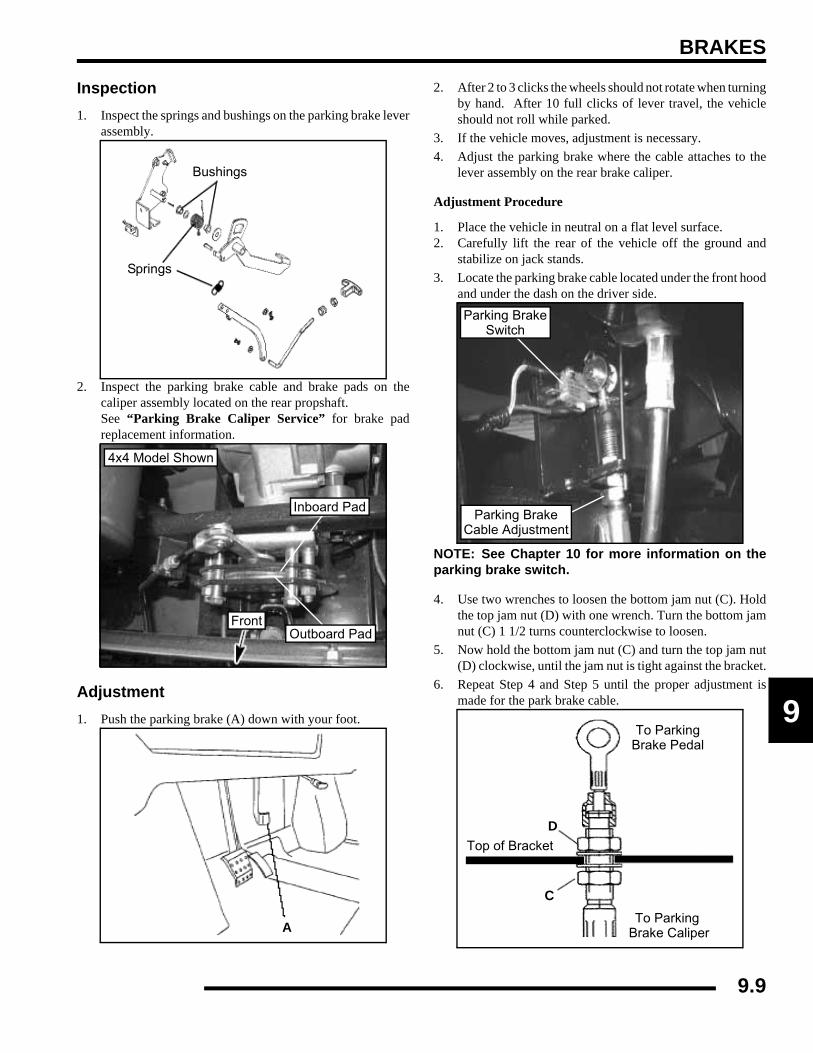
BRAKES
9
Inspection1. Inspect the springs and bushings on the parking brake lever
assembly.
2. Inspect the parking brake cable and brake pads on thecaliper assembly located on the rear propshaft. See “Parking Brake Caliper Service” for brake padreplacement information.
Adjustment1. Push the parking brake (A) down with your foot.
2. After 2 to 3 clicks the wheels should not rotate when turningby hand. After 10 full clicks of lever travel, the vehicleshould not roll while parked.
3. If the vehicle moves, adjustment is necessary.4. Adjust the parking brake where the cable attaches to the
lever assembly on the rear brake caliper.
Adjustment Procedure
1. Place the vehicle in neutral on a flat level surface.2. Carefully lift the rear of the vehicle off the ground and
stabilize on jack stands.3. Locate the parking brake cable located under the front hood
and under the dash on the driver side.
NOTE: See Chapter 10 for more information on theparking brake switch.
4. Use two wrenches to loosen the bottom jam nut (C). Holdthe top jam nut (D) with one wrench. Turn the bottom jamnut (C) 1 1/2 turns counterclockwise to loosen.
5. Now hold the bottom jam nut (C) and turn the top jam nut(D) clockwise, until the jam nut is tight against the bracket.
6. Repeat Step 4 and Step 5 until the proper adjustment ismade for the park brake cable.
Bushings
Springs
Front
Inboard Pad
Outboard Pad
4x4 Model Shown
A
Parking BrakeSwitch
Parking BrakeCable Adjustment
D
C
Top of Bracket
To ParkingBrake Pedal
To Parking Brake Caliper
9.9

BRAKES
PARKING BRAKE CALIPER SERVICEExploded View
Caliper RemovalNOTE: Do no get oil, grease, or fluid on the parkbrake pads. Damage to or contamination of the padsmay cause the pads to function improperly.
1. Remove the clip pin and pin (A) from the park brake cable.
NOTE: Be sure the park brake is not engaged.
2. If replacing the brake pads, slightly loosen the caliperassembly bolts before removing the complete caliperassembly. This will ease the caliper disassembly procedurelater.
Pad & Holder
Nut
Hex HeadMount Bolt
Sleeve Thrust Washer
Shim Pack(4 Shims)
Pad & Holder
Lever
Asm. Bolt
Steel Balls (3)
Plain Washer
Hex Nut
Stationary Actuator
Compression SpringSpring Pin
Figure 9.10
18 ft. lbs.
25 ft. lbs.
(24 Nm)
(34 Nm)
A
4x4 Model Shown
4x4 Model Shown
9.10

BRAKES
9
3. Loosen the two brake caliper mount bolts (B) in equalincrements.
4. Remove the bolts from the frame and lift park brakeassembly out.
Caliper Disassembly / InspectionNOTE: The rear park brake caliper assembly isreplaced as an assembly. Refer to your parts bookfor information.
5. Remove the two caliper assembly nuts (C) that werepreviously loosened during Step 2 of “Caliper Removal”.
6. Slide the brake pads and springs from the assembly.
NOTE: Retain the lever and ball bearings forreassembly.
7. Inspect the brake pads linings for excessive wear. Replaceas needed.
8. Check the three steel balls for any signs of cracking.Replace as needed.
9. Check ball seats in lever and stationary actuator. Ifexcessively worn, replace parts as needed.
10. Measure the thickness of the rear caliper parking brakepads. Replace assembly or pads as needed. See illustrationbelow for proper readings.
B
4x4 Model Shown
4x4 Model Shown
C
InboardPad
OutboardPad
Inboard pad thicknessNew .304” (7.72 mm)Limit: 0.24” (6.1 mm)
Outboard Pad ThicknessNew 0.360” (9.14 mm)Limit: 0.31” (7.87 mm)
Installed Disc to Park Brake0.375” (0.953 cm)
New Rotor Disc Thickness0.150” - 0.164
(3.81 - 4.16 mm)
9.11
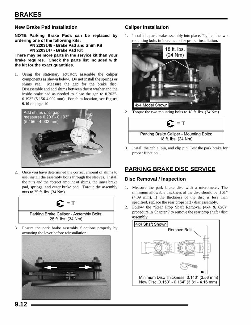
BRAKES
New Brake Pad InstallationNOTE: Parking Brake Pads can be replaced byordering one of the following kits:
PN 2203148 - Brake Pad and Shim KitPN 2203147 - Brake Pad Kit
There may be more parts in the service kit than yourbrake requires. Check the parts list included withthe kit for the exact quantities.
1. Using the stationary actuator, assemble the calipercomponents as shown below. Do not install the springs orshims yet. Measure the gap for the brake disc.Disassemble and add shims between thrust washer and theinside brake pad as needed to close the gap to 0.203”-0.193” (5.156-4.902 mm). For shim location, see Figure9.10 on page 10.
2. Once you have determined the correct amount of shims touse, install the assembly bolts through the sleeves. Installthe nuts and the correct amount of shims, the inner brakepad, springs, and outer brake pad. Torque the assemblynuts to 25 ft. lbs. (34 Nm).
3. Ensure the park brake assembly functions properly byactuating the lever before reinstallation.
Caliper Installation1. Install the park brake assembly into place. Tighten the two
mounting bolts in increments for proper installation.
2. Torque the two mounting bolts to 18 ft. lbs. (24 Nm).
3. Install the cable, pin, and clip pin. Test the park brake forproper function.
PARKING BRAKE DISC SERVICEDisc Removal / Inspection1. Measure the park brake disc with a micrometer. The
minimum allowable thickness of the disc should be .161”(4.09 mm). If the thickness of the disc is less thanspecified, replace the rear propshaft / disc assembly.
2. Follow the “Rear Prop Shaft Removal (4x4 & 6x6)”procedure in Chapter 7 to remove the rear prop shaft / discassembly.
= T
Parking Brake Caliper - Assembly Bolts: 25 ft. lbs. (34 Nm)
Add shims until gapmeasures 0.203”- 0.193”(5.156 - 4.902 mm) = T
Parking Brake Caliper - Mounting Bolts: 18 ft. lbs. (24 Nm)
18 ft. lbs.(24 Nm)
4x4 Model Shown
Remove Bolts
Minimum Disc Thickness: 0.140” (3.56 mm)New Disc: 0.150” - 0.164” (3.81 - 4.16 mm)
4x4 Shaft Shown
9.12
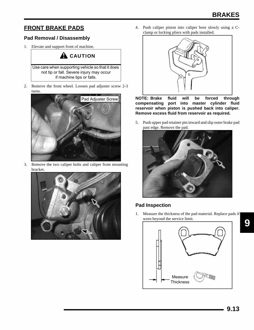
BRAKES
9
FRONT BRAKE PADSPad Removal / Disassembly1. Elevate and support front of machine.
2. Remove the front wheel. Loosen pad adjuster screw 2-3turns.
3. Remove the two caliper bolts and caliper from mountingbracket.
4. Push caliper piston into caliper bore slowly using a C-clamp or locking pliers with pads installed.
NOTE: Brake fluid will be forced throughcompensating port into master cylinder fluidreservoir when piston is pushed back into caliper.Remove excess fluid from reservoir as required.
5. Push upper pad retainer pin inward and slip outer brake padpast edge. Remove the pad.
Pad Inspection1. Measure the thickness of the pad material. Replace pads if
worn beyond the service limit.
CAUTION
Use care when supporting vehicle so that it does not tip or fall. Severe injury may occur
if machine tips or falls.
Pad Adjuster Screw
MeasureThickness
9.13
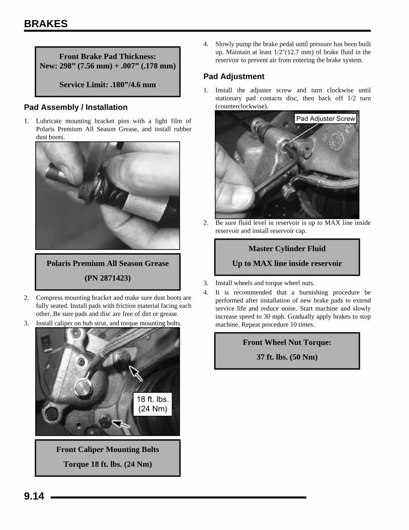
BRAKES
Pad Assembly / Installation1. Lubricate mounting bracket pins with a light film of
Polaris Premium All Season Grease, and install rubberdust boots.
2. Compress mounting bracket and make sure dust boots arefully seated. Install pads with friction material facing eachother. Be sure pads and disc are free of dirt or grease.
3. Install caliper on hub strut, and torque mounting bolts.
4. Slowly pump the brake pedal until pressure has been builtup. Maintain at least 1/2"(12.7 mm) of brake fluid in thereservoir to prevent air from entering the brake system.
Pad Adjustment1. Install the adjuster screw and turn clockwise until
stationary pad contacts disc, then back off 1/2 turn(counterclockwise).
2. Be sure fluid level in reservoir is up to MAX line insidereservoir and install reservoir cap.
3. Install wheels and torque wheel nuts.4. It is recommended that a burnishing procedure be
performed after installation of new brake pads to extendservice life and reduce noise. Start machine and slowlyincrease speed to 30 mph. Gradually apply brakes to stopmachine. Repeat procedure 10 times.
Front Brake Pad Thickness:New: 298” (7.56 mm) + .007” (.178 mm)
Service Limit: .180”/4.6 mm
Polaris Premium All Season Grease
(PN 2871423)
Front Caliper Mounting Bolts
Torque 18 ft. lbs. (24 Nm)
18 ft. lbs.(24 Nm)
Master Cylinder Fluid
Up to MAX line inside reservoir
Front Wheel Nut Torque:
37 ft. lbs. (50 Nm)
Pad Adjuster Screw
9.14

BRAKES
9
FRONT CALIPERFront Caliper Exploded View
Caliper Removal1. Elevate and support front of machine.
2. Remove the front wheel.3. Remove brake line from the caliper. Place a container under
caliper to catch fluid draining from brake line.
4. Remove brake caliper mounting bolts and caliper.
Caliper Disassembly1. Remove brake pad adjuster screw (A).
2. Push upper pad retainer pin inward and slip brake pads pastedge, if pads are still installed.
3. Remove mounting bracket (B) and dust boot (C)
Bleeder Screw30-60 in. lbs. (3.4-6.8 Nm)
Adjuster Screw(Finger Tight)
Caliper Body
Piston
Caliper Mount
Pads
Dust Boots
Square O-rings
FRONT CALIPER EXPLODED VIEW DURING ASSEMBLY
4 4
4
4
CAUTION
Use care when supporting vehicle so that it does not tip or fall. Severe injury may occur
if machine tips or falls.
A
B
C
D
E
F
Figure 9.15
9.15
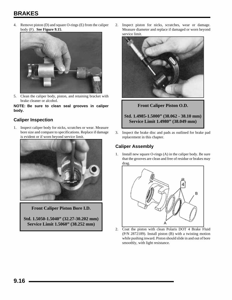
BRAKES
4. Remove piston (D) and square O-rings (E) from the caliperbody (F). See Figure 9.15.
5. Clean the caliper body, piston, and retaining bracket withbrake cleaner or alcohol.
NOTE: Be sure to clean seal grooves in caliperbody.
Caliper Inspection1. Inspect caliper body for nicks, scratches or wear. Measure
bore size and compare to specifications. Replace if damageis evident or if worn beyond service limit.
2. Inspect piston for nicks, scratches, wear or damage.Measure diameter and replace if damaged or worn beyondservice limit.
3. Inspect the brake disc and pads as outlined for brake padreplacement in this chapter.
Caliper Assembly1. Install new square O-rings (A) in the caliper body. Be sure
that the grooves are clean and free of residue or brakes maydrag.
2. Coat the piston with clean Polaris DOT 4 Brake Fluid(P/N 2872189). Install piston (B) with a twisting motionwhile pushing inward. Piston should slide in and out of boresmoothly, with light resistance.
Front Caliper Piston Bore I.D.
Std. 1.5050-1.5040” (32.27-30.202 mm)Service Limit 1.5060” (38.252 mm)
Front Caliper Piston O.D.
Std. 1.4985-1.5000” (38.062 - 38.10 mm)Service Limit 1.4980” (38.049 mm)
A
B
4
9.16

BRAKES
9
3. Lubricate the mounting bracket pins with Polaris PremiumAll Season Grease (PN 2871423), and install the rubberdust seal boots.
4. Compress the mounting bracket and make sure the dustseals are fully seated. Install the brake pads. Clean the discand pads with brake parts cleaner or denatured alcohol toremove any dirt, oil or grease.
Caliper Installation1. Install caliper on hub strut, and torque mounting bolts.
2. Install brake line and tighten securely with a flare nutwrench.
3. Install the adjuster screw and turn until stationary padcontacts disc, then back off 1/2 turn.
4. Follow brake bleeding procedure outlined earlier in thischapter.
5. Install wheels and torque wheel nuts to specification.
NOTE: If new brake pads are installed, it isrecommended that a burnishing procedure beperformed to extend pad service life and reducenoise. Start machine and slowly increase speed to15 mph. Gradually apply brakes to stop machine.Repeat procedure 10 times.
CAUTION
Do not allow grease to come into contact with the piston and seals.
Damage may occur to the components.
Front Caliper Mounting Bolt Torque:
18 ft. lbs. (24 Nm)
18 ft. lbs.(24 Nm)
Front Wheel Nut Torque:
37 ft. lbs. (50 Nm)
Pad Adjuster Screw
9.17
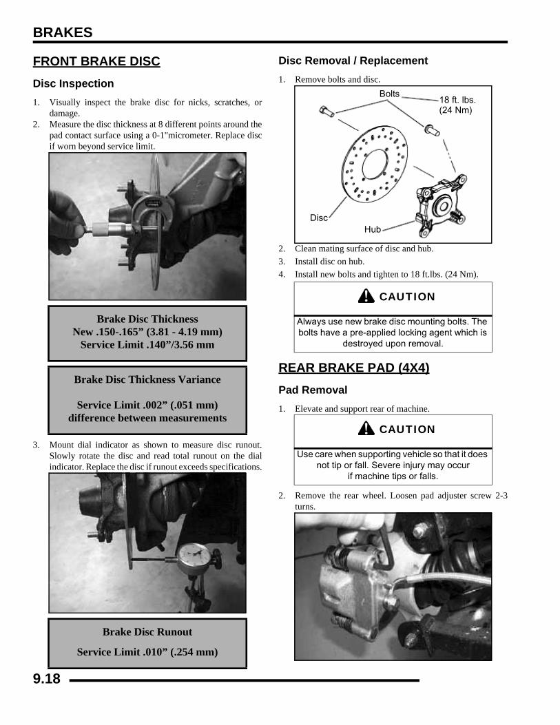
BRAKES
FRONT BRAKE DISCDisc Inspection1. Visually inspect the brake disc for nicks, scratches, or
damage.2. Measure the disc thickness at 8 different points around the
pad contact surface using a 0-1"micrometer. Replace discif worn beyond service limit.
3. Mount dial indicator as shown to measure disc runout.Slowly rotate the disc and read total runout on the dialindicator. Replace the disc if runout exceeds specifications.
Disc Removal / Replacement1. Remove bolts and disc.
2. Clean mating surface of disc and hub.3. Install disc on hub.4. Install new bolts and tighten to 18 ft.lbs. (24 Nm).
REAR BRAKE PAD (4X4)Pad Removal1. Elevate and support rear of machine.
2. Remove the rear wheel. Loosen pad adjuster screw 2-3turns.
Brake Disc ThicknessNew .150-.165” (3.81 - 4.19 mm)
Service Limit .140”/3.56 mm
Brake Disc Thickness Variance
Service Limit .002” (.051 mm)difference between measurements
Brake Disc Runout
Service Limit .010” (.254 mm)
CAUTION
Always use new brake disc mounting bolts. The bolts have a pre-applied locking agent which is
destroyed upon removal.
CAUTION
Use care when supporting vehicle so that it does not tip or fall. Severe injury may occur
if machine tips or falls.
Bolts18 ft. lbs.(24 Nm)
DiscHub
9.18
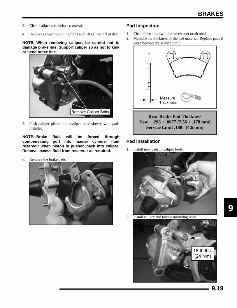
BRAKES
9
3. Clean caliper area before removal.
4. Remove caliper mounting bolts and lift caliper off of disc.
NOTE: When removing caliper, be careful not todamage brake line. Support caliper so as not to kinkor bend brake line.
5. Push caliper piston into caliper bore slowly with padsinstalled.
NOTE: Brake fluid will be forced throughcompensating port into master cylinder fluidreservoir when piston is pushed back into caliper.Remove excess fluid from reservoir as required.
6. Remove the brake pads.
Pad Inspection1. Clean the caliper with brake cleaner or alcohol.2. Measure the thickness of the pad material. Replace pads if
worn beyond the service limit.
Pad Installation1. Install new pads in caliper body.
2. Install caliper and torque mounting bolts.
Remove Caliper BoltsRear Brake Pad Thickness
New .298 + .007” (7.56 + .178 mm)Service Limit .180” (4.6 mm)
MeasureThickness
18 ft. lbs.(24 Nm)
9.19
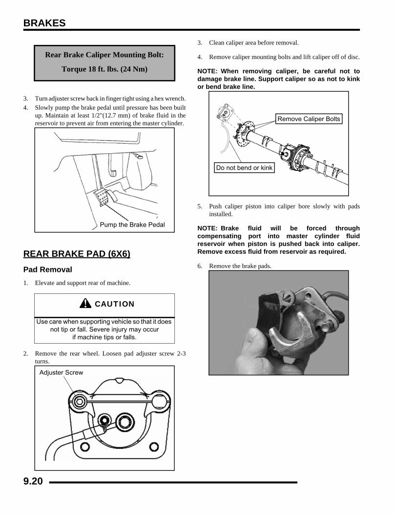
BRAKES
3. Turn adjuster screw back in finger tight using a hex wrench.4. Slowly pump the brake pedal until pressure has been built
up. Maintain at least 1/2"(12.7 mm) of brake fluid in thereservoir to prevent air from entering the master cylinder.
REAR BRAKE PAD (6X6)Pad Removal1. Elevate and support rear of machine.
2. Remove the rear wheel. Loosen pad adjuster screw 2-3turns.
3. Clean caliper area before removal.
4. Remove caliper mounting bolts and lift caliper off of disc.
NOTE: When removing caliper, be careful not todamage brake line. Support caliper so as not to kinkor bend brake line.
5. Push caliper piston into caliper bore slowly with padsinstalled.
NOTE: Brake fluid will be forced throughcompensating port into master cylinder fluidreservoir when piston is pushed back into caliper.Remove excess fluid from reservoir as required.
6. Remove the brake pads.
Rear Brake Caliper Mounting Bolt:
Torque 18 ft. lbs. (24 Nm)
CAUTION
Use care when supporting vehicle so that it does not tip or fall. Severe injury may occur
if machine tips or falls.
Pump the Brake Pedal
Adjuster Screw
Remove Caliper Bolts
Do not bend or kink
9.20
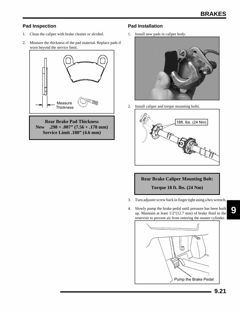
BRAKES
9
Pad Inspection1. Clean the caliper with brake cleaner or alcohol.
2. Measure the thickness of the pad material. Replace pads ifworn beyond the service limit.
Pad Installation1. Install new pads in caliper body.
2. Install caliper and torque mounting bolts.
3. Turn adjuster screw back in finger tight using a hex wrench.
4. Slowly pump the brake pedal until pressure has been builtup. Maintain at least 1/2"(12.7 mm) of brake fluid in thereservoir to prevent air from entering the master cylinder.
Rear Brake Pad ThicknessNew .298 + .007” (7.56 + .178 mm)
Service Limit .180” (4.6 mm)
MeasureThickness
Rear Brake Caliper Mounting Bolt:
Torque 18 ft. lbs. (24 Nm)
18ft. lbs. (24 Nm)
Pump the Brake Pedal
9.21
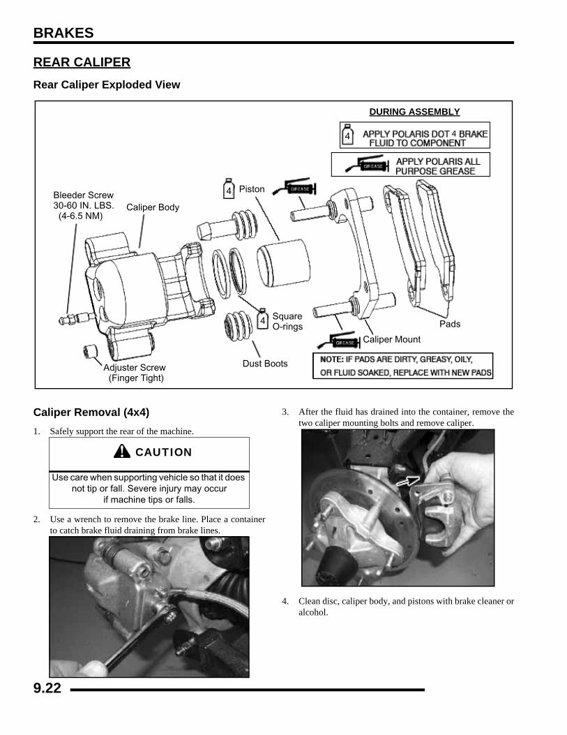
BRAKES
REAR CALIPERRear Caliper Exploded View
Caliper Removal (4x4)1. Safely support the rear of the machine.
2. Use a wrench to remove the brake line. Place a containerto catch brake fluid draining from brake lines.
3. After the fluid has drained into the container, remove thetwo caliper mounting bolts and remove caliper.
4. Clean disc, caliper body, and pistons with brake cleaner oralcohol.
Bleeder Screw30-60 IN. LBS. (4-6.5 NM)
Adjuster Screw (Finger Tight)
Caliper Body
Piston
Caliper Mount
Pads
Dust Boots
Square O-rings
DURING ASSEMBLY
4 4
4
4
CAUTION
Use care when supporting vehicle so that it does not tip or fall. Severe injury may occur
if machine tips or falls.
9.22
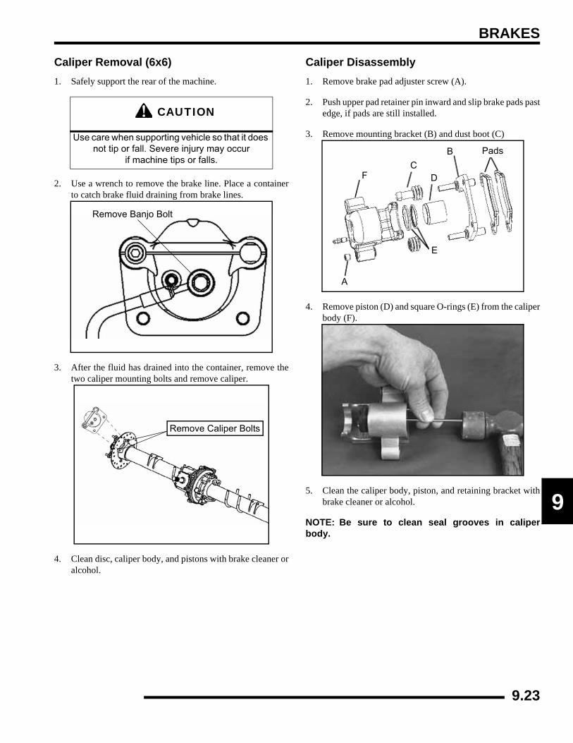
BRAKES
9
Caliper Removal (6x6)1. Safely support the rear of the machine.
2. Use a wrench to remove the brake line. Place a containerto catch brake fluid draining from brake lines.
3. After the fluid has drained into the container, remove thetwo caliper mounting bolts and remove caliper.
4. Clean disc, caliper body, and pistons with brake cleaner oralcohol.
Caliper Disassembly1. Remove brake pad adjuster screw (A).
2. Push upper pad retainer pin inward and slip brake pads pastedge, if pads are still installed.
3. Remove mounting bracket (B) and dust boot (C)
4. Remove piston (D) and square O-rings (E) from the caliperbody (F).
5. Clean the caliper body, piston, and retaining bracket withbrake cleaner or alcohol.
NOTE: Be sure to clean seal grooves in caliperbody.
CAUTION
Use care when supporting vehicle so that it does not tip or fall. Severe injury may occur
if machine tips or falls.
Remove Banjo Bolt
Remove Caliper Bolts
Pads
A
B
CD
E
F
9.23

BRAKES
Caliper Inspection1. Inspect caliper body for nicks, scratches or wear. Measure
bore size and compare to specifications. Replace if damageis evident or if worn beyond service limit.
2. Inspect piston for nicks, scratches, wear or damage.Measure diameter and replace if damaged or worn beyondservice limit.
3. Inspect the brake disc and pads as outlined for brake padreplacement in this chapter.
Caliper Assembly1. Install new square O-rings (A) in the caliper body. Be sure
that the grooves are clean and free of residue or brakes maydrag.
2. Coat the piston with clean Polaris DOT 4 Brake Fluid(P/N 2872189). Install piston (B) with a twisting motionwhile pushing inward. Piston should slide in and out of boresmoothly, with light resistance.
3. Lubricate the mounting bracket pins with Polaris PremiumAll Season Grease, and install the rubber dust seal boots.
4. Compress the mounting bracket and make sure the dustseals are fully seated. Install the brake pads. Clean the discand pads with brake parts cleaner or denatured alcohol toremove any dirt, oil or grease.
Rear Caliper Piston Bore I.D.
Std. 1.2550” (3.227 mm)Service Limit 1.256” (31.902 mm)
Rear Caliper piston O.D.
Std. 1.250” (31.75 mm)Service Limit 1.2495” (31.737 mm)
Polaris Premium All Season Grease
(PN 2871423)
A
B4
9.24

BRAKES
9
Caliper Installation (4x4, 6x6)1. Install the rear caliper with the mounting bolts. Torque
mounting bolts to 18 ft.lbs. (24 Nm).
2. Install brake line banjo bolt. Torque banjo bolt to 15 ft. lbs.(21 Nm).
3. Install the rear wheel and wheel nuts. Carefully lower thevehicle.
REAR BRAKE DISCDisc Inspection1. Visually inspect disc for scoring, scratches, or gouges.
Replace the disc if any deep scratches are evident.2. Use a 0-1"micrometer and measure disc thickness at 8
different points around perimeter of disc. Replace disc ifworn beyond service limit.
3. Mount dial indicator and measure disc runout. Replace thedisc if runout exceeds specifications.
4. Install brake line and tighten with a flare nut wrench.5. Follow bleeding procedure outlined earlier in this chapter.6. Field test unit for proper braking action before putting into
service. Inspect for fluid leaks and firm brakes. Make surethe brake is not dragging when pedal is released. If the brakedrags, re-check assembly and installation.
18 ft. lbs.(24 Nm)
15 ft. lbs.(21 Nm)
4X4
15 ft. lbs.(21 Nm)
18 ft. lbs.(24 Nm)
6X6
Brake Disc ThicknessNew .150-.165” (3.81-4.19 mm)Service Limit .140” (3.56 mm)
Brake Disc Thickness Variance
Service Limit .002” (.051 mm)difference between measurements
Brake Disc RunoutService Limit .010” (.254 mm)
Rear Brake Disc
Rear Brake
MeasureThickness
Disc
Front View of Brake Disc
9.25
BRAKES
TROUBLESHOOTINGBrakes Squeal / Poor Brake Performance
• Air in system
• Water in system (brake fluid contaminated)
• Caliper/disc misaligned
• Caliper dirty or damaged
• Brake line damaged or lining ruptured
• Worn disc and/or friction pads
• Incorrectly adjusted stationary pad
• Worn or damaged master cylinder or components
• Damaged break pad noise insulator
Pedal Vibration• Disc damaged
• Disc worn (runout or thickness variance exceeds service limit)
Caliper Overheats (Brakes Drag)• Compensating port plugged
• Pad clearance set incorrectly
• Parking brake lever incorrectly adjusted
• Brake pedal binding or unable to return fully
• Parking brake left on
• Residue build up under caliper seals
• Operator riding brakes
Brakes Lock• Alignment of caliper to disc
• Caliper pistons sticking
• Improper assembly of brake system components
9.26
ELECTRICAL
CHAPTER 10ELECTRICAL
10
GENERAL INFORMATION . . . . . . . . . . . . . . . . . . . . . . . . . . . . . . . . . . . . . . . . . . . . . . . 10.3SPECIAL TOOLS . . . . . . . . . . . . . . . . . . . . . . . . . . . . . . . . . . . . . . . . . . . . . . . . . . . . . . 10.3ELECTRICAL SERVICE NOTES . . . . . . . . . . . . . . . . . . . . . . . . . . . . . . . . . . . . . . . . . . 10.3UNDER-HOOD COMPONENTS . . . . . . . . . . . . . . . . . . . . . . . . . . . . . . . . . . . . . . . . . . 10.3
SWITCHES / CONTROLS . . . . . . . . . . . . . . . . . . . . . . . . . . . . . . . . . . . . . . . . . . . . . . . 10.4HEADLAMP SWITCH. . . . . . . . . . . . . . . . . . . . . . . . . . . . . . . . . . . . . . . . . . . . . . . . . . . 10.4AWD / REAR DIFFERENTIAL SWITCH (4X4) . . . . . . . . . . . . . . . . . . . . . . . . . . . . . . . . 10.4DIFFERENTIAL SOLENOID (4X4) . . . . . . . . . . . . . . . . . . . . . . . . . . . . . . . . . . . . . . . . . 10.4BRAKE LIGHT SWITCH. . . . . . . . . . . . . . . . . . . . . . . . . . . . . . . . . . . . . . . . . . . . . . . . . 10.5PARKING BRAKE SWITCH . . . . . . . . . . . . . . . . . . . . . . . . . . . . . . . . . . . . . . . . . . . . . . 10.6
INSTRUMENT CLUSTER . . . . . . . . . . . . . . . . . . . . . . . . . . . . . . . . . . . . . . . . . . . . . . . . 10.7OVERVIEW. . . . . . . . . . . . . . . . . . . . . . . . . . . . . . . . . . . . . . . . . . . . . . . . . . . . . . . . . . . 10.7RIDER INFORMATION DISPLAY . . . . . . . . . . . . . . . . . . . . . . . . . . . . . . . . . . . . . . . . . 10.7STANDARD DISPLAY MODES . . . . . . . . . . . . . . . . . . . . . . . . . . . . . . . . . . . . . . . . . . . 10.8DIAGNOSTIC DISPLAY MODE . . . . . . . . . . . . . . . . . . . . . . . . . . . . . . . . . . . . . . . . . . . 10.8VIEWING DIAGNOSTIC CODES . . . . . . . . . . . . . . . . . . . . . . . . . . . . . . . . . . . . . . . . . 10.10INSTRUMENT CLUSTER REMOVAL . . . . . . . . . . . . . . . . . . . . . . . . . . . . . . . . . . . . . 10.11INSTRUMENT CLUSTER INSTALLATION . . . . . . . . . . . . . . . . . . . . . . . . . . . . . . . . . 10.11
INSTRUMENT CLUSTER TROUBLESHOOTING TESTS . . . . . . . . . . . . . . . . . . . . . . 10.12TEST 1 - NO ALL WHEEL DRIVE . . . . . . . . . . . . . . . . . . . . . . . . . . . . . . . . . . . . . . . . 10.12TEST 2 - NO DISPLAY. . . . . . . . . . . . . . . . . . . . . . . . . . . . . . . . . . . . . . . . . . . . . . . . . 10.13TEST 3 - WHEEL SPEED SENSOR . . . . . . . . . . . . . . . . . . . . . . . . . . . . . . . . . . . . . . 10.13TEST 4 - NO AWD HUB SAFETY LIMITER. . . . . . . . . . . . . . . . . . . . . . . . . . . . . . . . . 10.14TEST 5 - FUEL GAUGE DISPLAY NOT WORKING . . . . . . . . . . . . . . . . . . . . . . . . . . 10.15TEST 6 - SHIFT INDICATOR NOT WORKING (TRANSMISSION SWITCH) . . . . . . . 10.15
ALL WHEEL DRIVE (AWD) COIL . . . . . . . . . . . . . . . . . . . . . . . . . . . . . . . . . . . . . . . . . 10.16OPERATION OVERVIEW . . . . . . . . . . . . . . . . . . . . . . . . . . . . . . . . . . . . . . . . . . . . . . 10.16DIAGNOSING SYSTEM FAILURES. . . . . . . . . . . . . . . . . . . . . . . . . . . . . . . . . . . . . . . 10.16
GEAR POSITION INDICATOR SWITCH. . . . . . . . . . . . . . . . . . . . . . . . . . . . . . . . . . . . 10.16TEST DIAGRAM. . . . . . . . . . . . . . . . . . . . . . . . . . . . . . . . . . . . . . . . . . . . . . . . . . . . . . 10.16
HEAD LIGHTS. . . . . . . . . . . . . . . . . . . . . . . . . . . . . . . . . . . . . . . . . . . . . . . . . . . . . . . . 10.17HIGH BEAM HEADLIGHT ADJUSTMENT. . . . . . . . . . . . . . . . . . . . . . . . . . . . . . . . . . 10.17HEADLAMP BULB REPLACEMENT . . . . . . . . . . . . . . . . . . . . . . . . . . . . . . . . . . . . . . 10.17HEADLAMP HOUSING REMOVAL . . . . . . . . . . . . . . . . . . . . . . . . . . . . . . . . . . . . . . . 10.17HEADLAMP HOUSING INSTALLATION . . . . . . . . . . . . . . . . . . . . . . . . . . . . . . . . . . . 10.18
TAIL LIGHT / BRAKE LIGHT. . . . . . . . . . . . . . . . . . . . . . . . . . . . . . . . . . . . . . . . . . . . . 10.18LAMP REPLACEMENT . . . . . . . . . . . . . . . . . . . . . . . . . . . . . . . . . . . . . . . . . . . . . . . . 10.18
COOLING SYSTEM. . . . . . . . . . . . . . . . . . . . . . . . . . . . . . . . . . . . . . . . . . . . . . . . . . . . 10.19COOLING SYSTEM BREAK-OUT DIAGRAM . . . . . . . . . . . . . . . . . . . . . . . . . . . . . . . 10.19FAN CONTROL CIRCUIT OPERATION / TESTING . . . . . . . . . . . . . . . . . . . . . . . . . . 10.20FAN CONTROL CIRCUIT BYPASS TEST. . . . . . . . . . . . . . . . . . . . . . . . . . . . . . . . . . 10.20COOLANT TEMPERATURE SENSOR . . . . . . . . . . . . . . . . . . . . . . . . . . . . . . . . . . . . 10.20
EFI DIAGNOSTICS . . . . . . . . . . . . . . . . . . . . . . . . . . . . . . . . . . . . . . . . . . . . . . . . . . . . 10.20EFI COMPONENT TESTING . . . . . . . . . . . . . . . . . . . . . . . . . . . . . . . . . . . . . . . . . . . . 10.20
FUEL SENDER . . . . . . . . . . . . . . . . . . . . . . . . . . . . . . . . . . . . . . . . . . . . . . . . . . . . . . . 10.20TESTING . . . . . . . . . . . . . . . . . . . . . . . . . . . . . . . . . . . . . . . . . . . . . . . . . . . . . . . . . . . 10.20
RELAYS. . . . . . . . . . . . . . . . . . . . . . . . . . . . . . . . . . . . . . . . . . . . . . . . . . . . . . . . . . . . . 10.21OPERATION. . . . . . . . . . . . . . . . . . . . . . . . . . . . . . . . . . . . . . . . . . . . . . . . . . . . . . . . . 10.21
FUSES / CIRCUIT BREAKER . . . . . . . . . . . . . . . . . . . . . . . . . . . . . . . . . . . . . . . . . . . . 10.22OPERATION. . . . . . . . . . . . . . . . . . . . . . . . . . . . . . . . . . . . . . . . . . . . . . . . . . . . . . . . . 10.22
10.1
ELECTRICAL
CHARGING SYSTEM . . . . . . . . . . . . . . . . . . . . . . . . . . . . . . . . . . . . . . . . . . . . . . . . . . 10.22CURRENT DRAW - KEY OFF . . . . . . . . . . . . . . . . . . . . . . . . . . . . . . . . . . . . . . . . . . . 10.22CHARGING SYSTEM “BREAK EVEN” TEST . . . . . . . . . . . . . . . . . . . . . . . . . . . . . . . 10.23CHARGING SYSTEM ALTERNATOR TESTS. . . . . . . . . . . . . . . . . . . . . . . . . . . . . . . 10.23CHARGING SYSTEM TESTING FLOW CHART . . . . . . . . . . . . . . . . . . . . . . . . . . . . . 10.25
BATTERY TERMINAL BLOCK . . . . . . . . . . . . . . . . . . . . . . . . . . . . . . . . . . . . . . . . . . . 10.26BATTERY SERVICE . . . . . . . . . . . . . . . . . . . . . . . . . . . . . . . . . . . . . . . . . . . . . . . . . . . 10.26
BATTERY TERMINALS / BOLTS. . . . . . . . . . . . . . . . . . . . . . . . . . . . . . . . . . . . . . . . . 10.26BATTERY IDENTIFICATION . . . . . . . . . . . . . . . . . . . . . . . . . . . . . . . . . . . . . . . . . . . . 10.26
CONVENTIONAL BATTERY. . . . . . . . . . . . . . . . . . . . . . . . . . . . . . . . . . . . . . . . . . . . . 10.27BATTERY ACTIVATION. . . . . . . . . . . . . . . . . . . . . . . . . . . . . . . . . . . . . . . . . . . . . . . . 10.27BATTERY INSPECTION . . . . . . . . . . . . . . . . . . . . . . . . . . . . . . . . . . . . . . . . . . . . . . . 10.27BATTERY REMOVAL. . . . . . . . . . . . . . . . . . . . . . . . . . . . . . . . . . . . . . . . . . . . . . . . . . 10.28BATTERY INSTALLATION. . . . . . . . . . . . . . . . . . . . . . . . . . . . . . . . . . . . . . . . . . . . . . 10.28CONVENTIONAL BATTERY TESTING . . . . . . . . . . . . . . . . . . . . . . . . . . . . . . . . . . . . 10.28OCV - OPEN CIRCUIT VOLTAGE TEST. . . . . . . . . . . . . . . . . . . . . . . . . . . . . . . . . . . 10.28SPECIFIC GRAVITY TEST . . . . . . . . . . . . . . . . . . . . . . . . . . . . . . . . . . . . . . . . . . . . . 10.28LOAD TEST . . . . . . . . . . . . . . . . . . . . . . . . . . . . . . . . . . . . . . . . . . . . . . . . . . . . . . . . . 10.29OFF SEASON STORAGE . . . . . . . . . . . . . . . . . . . . . . . . . . . . . . . . . . . . . . . . . . . . . . 10.29CHARGING PROCEDURE . . . . . . . . . . . . . . . . . . . . . . . . . . . . . . . . . . . . . . . . . . . . . 10.29
LOW MAINTENANCE BATTERY . . . . . . . . . . . . . . . . . . . . . . . . . . . . . . . . . . . . . . . . . 10.30BATTERY CHECK . . . . . . . . . . . . . . . . . . . . . . . . . . . . . . . . . . . . . . . . . . . . . . . . . . . . 10.30BATTERY INSPECTION . . . . . . . . . . . . . . . . . . . . . . . . . . . . . . . . . . . . . . . . . . . . . . . 10.30BATTERY REMOVAL. . . . . . . . . . . . . . . . . . . . . . . . . . . . . . . . . . . . . . . . . . . . . . . . . . 10.30BATTERY INSTALLATION. . . . . . . . . . . . . . . . . . . . . . . . . . . . . . . . . . . . . . . . . . . . . . 10.31BATTERY TESTING. . . . . . . . . . . . . . . . . . . . . . . . . . . . . . . . . . . . . . . . . . . . . . . . . . . 10.31OCV - OPEN CIRCUIT VOLTAGE TEST. . . . . . . . . . . . . . . . . . . . . . . . . . . . . . . . . . . 10.31LOAD TEST . . . . . . . . . . . . . . . . . . . . . . . . . . . . . . . . . . . . . . . . . . . . . . . . . . . . . . . . . 10.31OFF-SEASON STORAGE . . . . . . . . . . . . . . . . . . . . . . . . . . . . . . . . . . . . . . . . . . . . . . 10.32BATTERY CHARGING. . . . . . . . . . . . . . . . . . . . . . . . . . . . . . . . . . . . . . . . . . . . . . . . . 10.32
STARTER SYSTEM . . . . . . . . . . . . . . . . . . . . . . . . . . . . . . . . . . . . . . . . . . . . . . . . . . . 10.33TROUBLESHOOTING . . . . . . . . . . . . . . . . . . . . . . . . . . . . . . . . . . . . . . . . . . . . . . . . . 10.33VOLTAGE DROP TEST . . . . . . . . . . . . . . . . . . . . . . . . . . . . . . . . . . . . . . . . . . . . . . . . 10.33STARTER MOTOR REMOVAL / DISASSEMBLY . . . . . . . . . . . . . . . . . . . . . . . . . . . . 10.33BRUSH INSPECTION / REPLACEMENT . . . . . . . . . . . . . . . . . . . . . . . . . . . . . . . . . . 10.34ARMATURE TESTING. . . . . . . . . . . . . . . . . . . . . . . . . . . . . . . . . . . . . . . . . . . . . . . . . 10.35STARTER REASSEMBLY / INSTALLATION. . . . . . . . . . . . . . . . . . . . . . . . . . . . . . . . 10.35STARTER SOLENOID BENCH TEST . . . . . . . . . . . . . . . . . . . . . . . . . . . . . . . . . . . . . 10.36STARTER DRIVE. . . . . . . . . . . . . . . . . . . . . . . . . . . . . . . . . . . . . . . . . . . . . . . . . . . . . 10.36STARTER EXPLODED VIEW . . . . . . . . . . . . . . . . . . . . . . . . . . . . . . . . . . . . . . . . . . . 10.37
STARTER SYSTEM TESTING FLOW CHART. . . . . . . . . . . . . . . . . . . . . . . . . . . . . . . 10.38ELECTRIC BOX LIFT ACTUATOR . . . . . . . . . . . . . . . . . . . . . . . . . . . . . . . . . . . . . . . . 10.39
DIAGNOSIS (IF EQUIPPED) . . . . . . . . . . . . . . . . . . . . . . . . . . . . . . . . . . . . . . . . . . . . 10.39
10.2
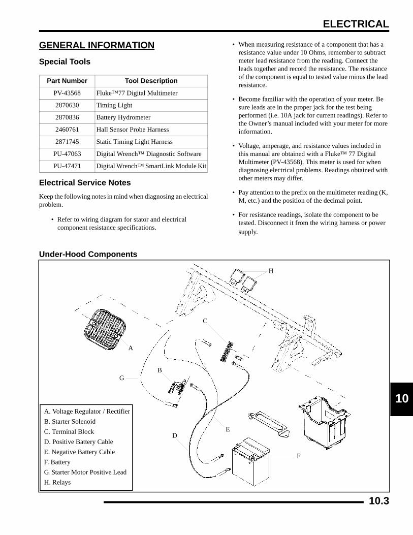
ELECTRICAL
0
1GENERAL INFORMATIONSpecial Tools
Electrical Service NotesKeep the following notes in mind when diagnosing an electricalproblem.
• Refer to wiring diagram for stator and electrical component resistance specifications.
• When measuring resistance of a component that has a resistance value under 10 Ohms, remember to subtract meter lead resistance from the reading. Connect the leads together and record the resistance. The resistance of the component is equal to tested value minus the lead resistance.
• Become familiar with the operation of your meter. Be sure leads are in the proper jack for the test being performed (i.e. 10A jack for current readings). Refer to the Owner’s manual included with your meter for more information.
• Voltage, amperage, and resistance values included in this manual are obtained with a Fluke™ 77 Digital Multimeter (PV-43568). This meter is used for when diagnosing electrical problems. Readings obtained with other meters may differ.
• Pay attention to the prefix on the multimeter reading (K, M, etc.) and the position of the decimal point.
• For resistance readings, isolate the component to be tested. Disconnect it from the wiring harness or power supply.
Under-Hood Components
Part Number Tool Description
PV-43568 Fluke™77 Digital Multimeter
2870630 Timing Light
2870836 Battery Hydrometer
2460761 Hall Sensor Probe Harness
2871745 Static Timing Light Harness
PU-47063 Digital Wrench™ Diagnostic Software
PU-47471 Digital Wrench™ SmartLink Module Kit
A
B
C
DE
F
G
A. Voltage Regulator / RectifierB. Starter SolenoidC. Terminal BlockD. Positive Battery CableE. Negative Battery CableF. BatteryG. Starter Motor Positive LeadH. Relays
H
10.3
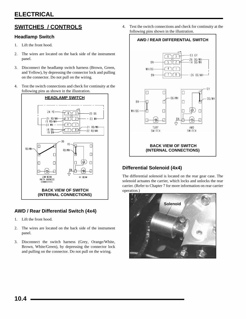
ELECTRICAL
SWITCHES / CONTROLSHeadlamp Switch1. Lift the front hood.
2. The wires are located on the back side of the instrumentpanel.
3. Disconnect the headlamp switch harness (Brown, Green,and Yellow), by depressing the connector lock and pullingon the connector. Do not pull on the wiring.
4. Test the switch connections and check for continuity at thefollowing pins as shown in the illustration.
AWD / Rear Differential Switch (4x4)1. Lift the front hood.
2. The wires are located on the back side of the instrumentpanel.
3. Disconnect the switch harness (Grey, Orange/White,Brown, White/Green), by depressing the connector lockand pulling on the connector. Do not pull on the wiring.
4. Test the switch connections and check for continuity at thefollowing pins shown in the illustration.
Differential Solenoid (4x4)The differential solenoid is located on the rear gear case. Thesolenoid actuates the carrier, which locks and unlocks the rearcarrier. (Refer to Chapter 7 for more information on rear carrieroperation.)
HEADLAMP SWITCH
BACK VIEW OF SWITCH(INTERNAL CONNECTIONS)
AWD / REAR DIFFERENTIAL SWITCH
BACK VIEW OF SWITCH(INTERNAL CONNECTIONS)
Solenoid
10.4
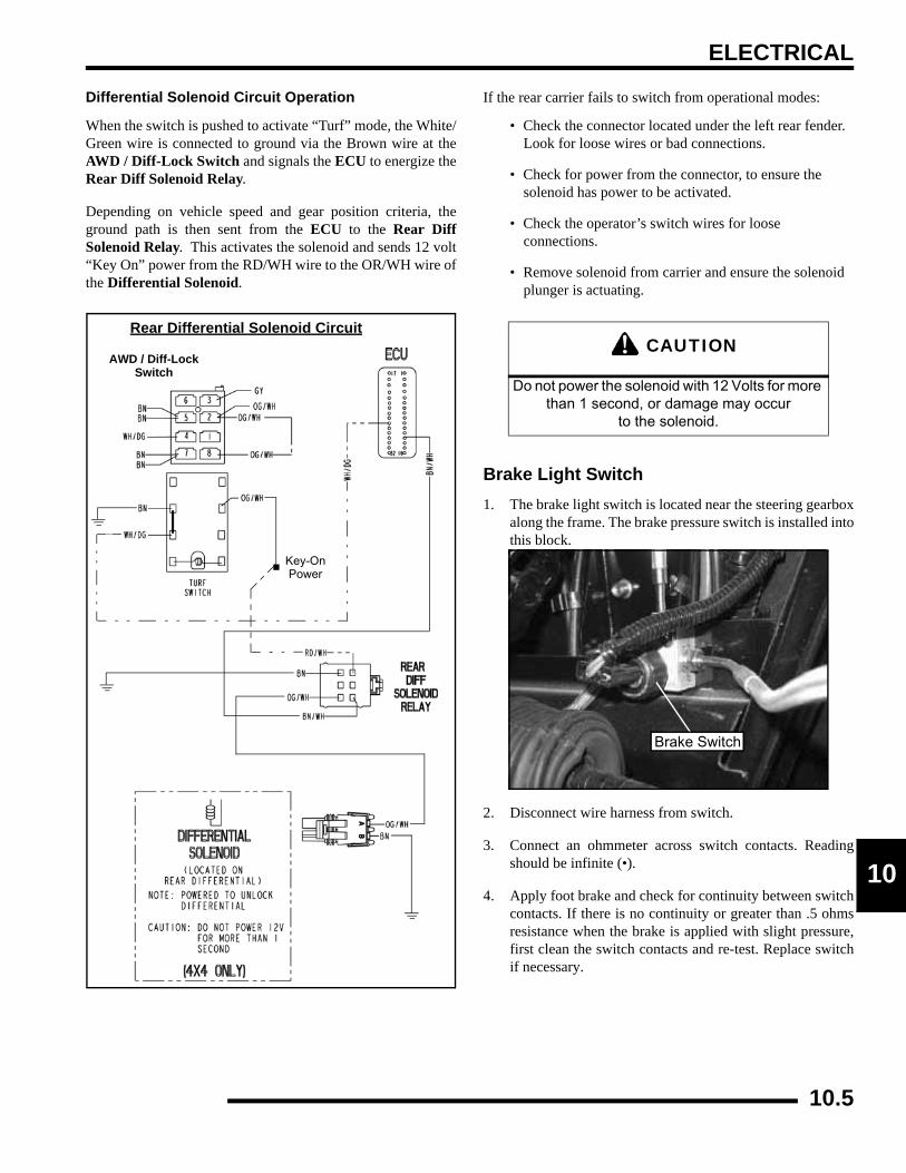
ELECTRICAL
0
1Differential Solenoid Circuit Operation
When the switch is pushed to activate “Turf” mode, the White/Green wire is connected to ground via the Brown wire at theAWD / Diff-Lock Switch and signals the ECU to energize theRear Diff Solenoid Relay.
Depending on vehicle speed and gear position criteria, theground path is then sent from the ECU to the Rear DiffSolenoid Relay. This activates the solenoid and sends 12 volt“Key On” power from the RD/WH wire to the OR/WH wire ofthe Differential Solenoid.
If the rear carrier fails to switch from operational modes:
• Check the connector located under the left rear fender. Look for loose wires or bad connections.
• Check for power from the connector, to ensure the solenoid has power to be activated.
• Check the operator’s switch wires for loose connections.
• Remove solenoid from carrier and ensure the solenoid plunger is actuating.
Brake Light Switch1. The brake light switch is located near the steering gearbox
along the frame. The brake pressure switch is installed intothis block.
2. Disconnect wire harness from switch.
3. Connect an ohmmeter across switch contacts. Readingshould be infinite (•).
4. Apply foot brake and check for continuity between switchcontacts. If there is no continuity or greater than .5 ohmsresistance when the brake is applied with slight pressure,first clean the switch contacts and re-test. Replace switchif necessary.
Rear Differential Solenoid Circuit
AWD / Diff-LockSwitch
Key-OnPower
CAUTION
Do not power the solenoid with 12 Volts for more than 1 second, or damage may occur
to the solenoid.
Brake Switch
10.5
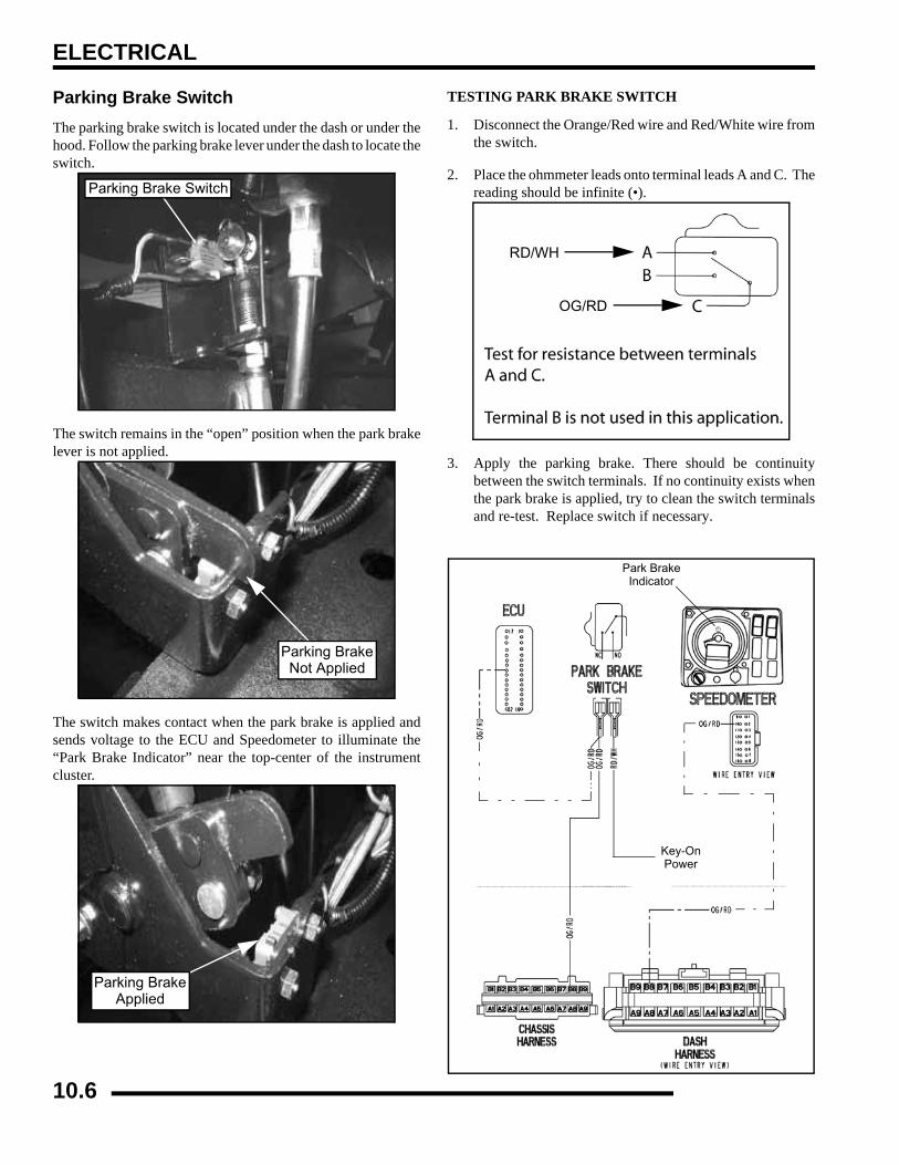
ELECTRICAL
Parking Brake SwitchThe parking brake switch is located under the dash or under thehood. Follow the parking brake lever under the dash to locate theswitch.
The switch remains in the “open” position when the park brakelever is not applied.
The switch makes contact when the park brake is applied andsends voltage to the ECU and Speedometer to illuminate the“Park Brake Indicator” near the top-center of the instrumentcluster.
TESTING PARK BRAKE SWITCH
1. Disconnect the Orange/Red wire and Red/White wire fromthe switch.
2. Place the ohmmeter leads onto terminal leads A and C. Thereading should be infinite (•).
3. Apply the parking brake. There should be continuitybetween the switch terminals. If no continuity exists whenthe park brake is applied, try to clean the switch terminalsand re-test. Replace switch if necessary.
Parking Brake Switch
Parking BrakeNot Applied
Parking BrakeApplied
RD/WH
OG/RD
Key-OnPower
P
Park BrakeIndicator
10.6
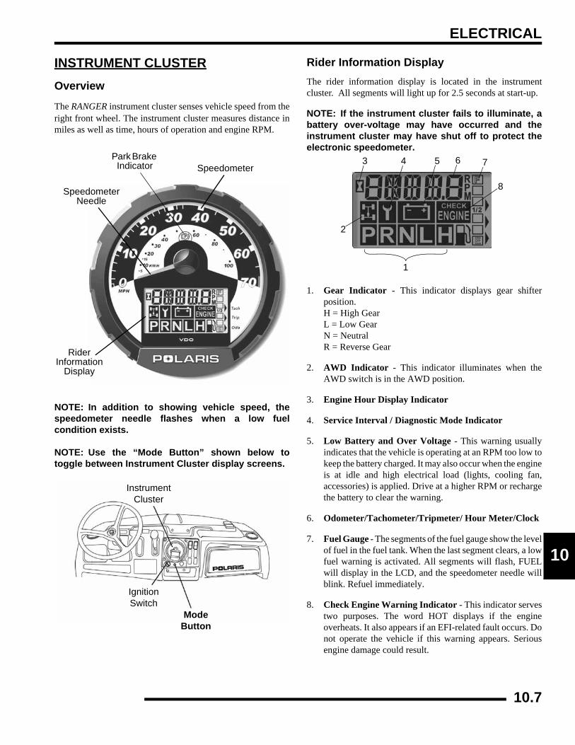
ELECTRICAL
0
1INSTRUMENT CLUSTEROverview
The RANGER instrument cluster senses vehicle speed from theright front wheel. The instrument cluster measures distance inmiles as well as time, hours of operation and engine RPM.
NOTE: In addition to showing vehicle speed, thespeedometer needle flashes when a low fuelcondition exists.
NOTE: Use the “Mode Button” shown below totoggle between Instrument Cluster display screens.
Rider Information DisplayThe rider information display is located in the instrumentcluster. All segments will light up for 2.5 seconds at start-up.
NOTE: If the instrument cluster fails to illuminate, abattery over-voltage may have occurred and theinstrument cluster may have shut off to protect theelectronic speedometer.
1. Gear Indicator - This indicator displays gear shifterposition.H = High GearL = Low GearN = NeutralR = Reverse Gear
2. AWD Indicator - This indicator illuminates when theAWD switch is in the AWD position.
3. Engine Hour Display Indicator
4. Service Interval / Diagnostic Mode Indicator
5. Low Battery and Over Voltage - This warning usuallyindicates that the vehicle is operating at an RPM too low tokeep the battery charged. It may also occur when the engineis at idle and high electrical load (lights, cooling fan,accessories) is applied. Drive at a higher RPM or rechargethe battery to clear the warning.
6. Odometer/Tachometer/Tripmeter/ Hour Meter/Clock
7. Fuel Gauge - The segments of the fuel gauge show the levelof fuel in the fuel tank. When the last segment clears, a lowfuel warning is activated. All segments will flash, FUELwill display in the LCD, and the speedometer needle willblink. Refuel immediately.
8. Check Engine Warning Indicator - This indicator servestwo purposes. The word HOT displays if the engineoverheats. It also appears if an EFI-related fault occurs. Donot operate the vehicle if this warning appears. Seriousengine damage could result.
RiderInformation
Display
Speedometer
Speedometer Needle
Park Brake Indicator
InstrumentCluster
ModeButton
IgnitionSwitch
1
2
3 4 5 6 7
8
10.7
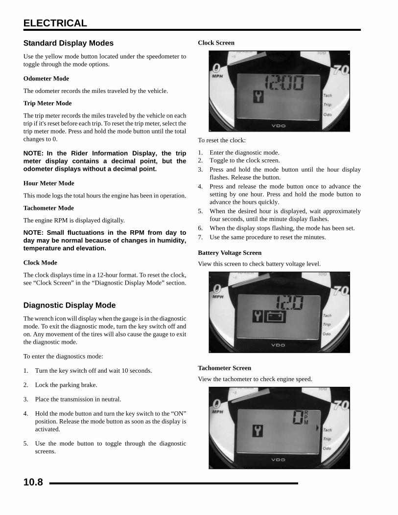
ELECTRICAL
Standard Display ModesUse the yellow mode button located under the speedometer totoggle through the mode options.
Odometer Mode
The odometer records the miles traveled by the vehicle.
Trip Meter Mode
The trip meter records the miles traveled by the vehicle on eachtrip if it's reset before each trip. To reset the trip meter, select thetrip meter mode. Press and hold the mode button until the totalchanges to 0.
NOTE: In the Rider Information Display, the tripmeter display contains a decimal point, but theodometer displays without a decimal point.
Hour Meter Mode
This mode logs the total hours the engine has been in operation.
Tachometer Mode
The engine RPM is displayed digitally.
NOTE: Small fluctuations in the RPM from day today may be normal because of changes in humidity,temperature and elevation.
Clock Mode
The clock displays time in a 12-hour format. To reset the clock,see “Clock Screen” in the “Diagnostic Display Mode” section.
Diagnostic Display ModeThe wrench icon will display when the gauge is in the diagnosticmode. To exit the diagnostic mode, turn the key switch off andon. Any movement of the tires will also cause the gauge to exitthe diagnostic mode.
To enter the diagnostics mode:
1. Turn the key switch off and wait 10 seconds.
2. Lock the parking brake.
3. Place the transmission in neutral.
4. Hold the mode button and turn the key switch to the “ON”position. Release the mode button as soon as the display isactivated.
5. Use the mode button to toggle through the diagnosticscreens.
Clock Screen
To reset the clock:
1. Enter the diagnostic mode.2. Toggle to the clock screen. 3. Press and hold the mode button until the hour display
flashes. Release the button. 4. Press and release the mode button once to advance the
setting by one hour. Press and hold the mode button toadvance the hours quickly.
5. When the desired hour is displayed, wait approximatelyfour seconds, until the minute display flashes.
6. When the display stops flashing, the mode has been set.7. Use the same procedure to reset the minutes.
Battery Voltage Screen
View this screen to check battery voltage level.
Tachometer Screen
View the tachometer to check engine speed.
10.8

ELECTRICAL
0
1AWD Diagnostic Screen
The gauge indicates whether or not current is flowing throughthe AWD coil.
Gear Circuit Diagnostic Screen
This screen displays the resistance value (in ohms) being read atthe gear switch input of the gauge.
NOTE: A 10 - 20% variance from these readings iswithin normal parameters.
Programmable Service Interval
When the hours of engine operation equal the programmedservice interval setting, the wrench icon will flash for 5 secondseach time the engine is started. When this feature is enabled, itprovides a convenient reminder to perform routinemaintenance.
NOTE: The service interval is programmed at 50hours at the factory.
10.9

ELECTRICAL
To enable or disable the service interval:
1. Enter the diagnostic mode.
2. Toggle to the service interval screen.
3. Press and hold the mode button for about seven (7) seconds,until either ON or OFF appears in the Rider InformationDisplay, depending on your preference.
To reset the service interval:
1. Enter the diagnostic mode.
2. Toggle to the service interval screen.
3. Press and hold the mode button for 2-3 seconds, until thewrench icon flashes. Release the button.
4. Press and release the mode button once to advance thesetting by one hour. Press and hold the mode button toadvance the hours quickly.
NOTE: If you scroll past the intended number, pressand hold the button until the hours cycle back tozero.
5. When the desired setting is displayed, wait until the wrenchicon stops flashing. The new service interval is nowprogrammed.
Miles / Kilometers Toggle
The display in the tripmeter and odometer can be changed todisplay either standard or metric units of measurement.
1. Enter the diagnostic mode.
2. Toggle to the screen that displays either kilometers (KM)or miles (MP).
3. Press and hold the mode button until the letters flash, thenpress and release the button once. When the display stopsflashing, the mode has been set.
Viewing Diagnostic CodesUse the following procedure to view diagnostic blink codes(failure codes) from the EFI module.
NOTE: See Page 4.21 for a complete list ofDiagnostic Blink Codes
1. Engage the parking brake.
2. Stop the engine.
3. Turn the key switch to the ON position.
4. Turn the key switch off and on three times in less than fiveseconds, then leave the switch on. The word “Wait” willappear on the screen along with a flashing “Check Engine”light.
10.10
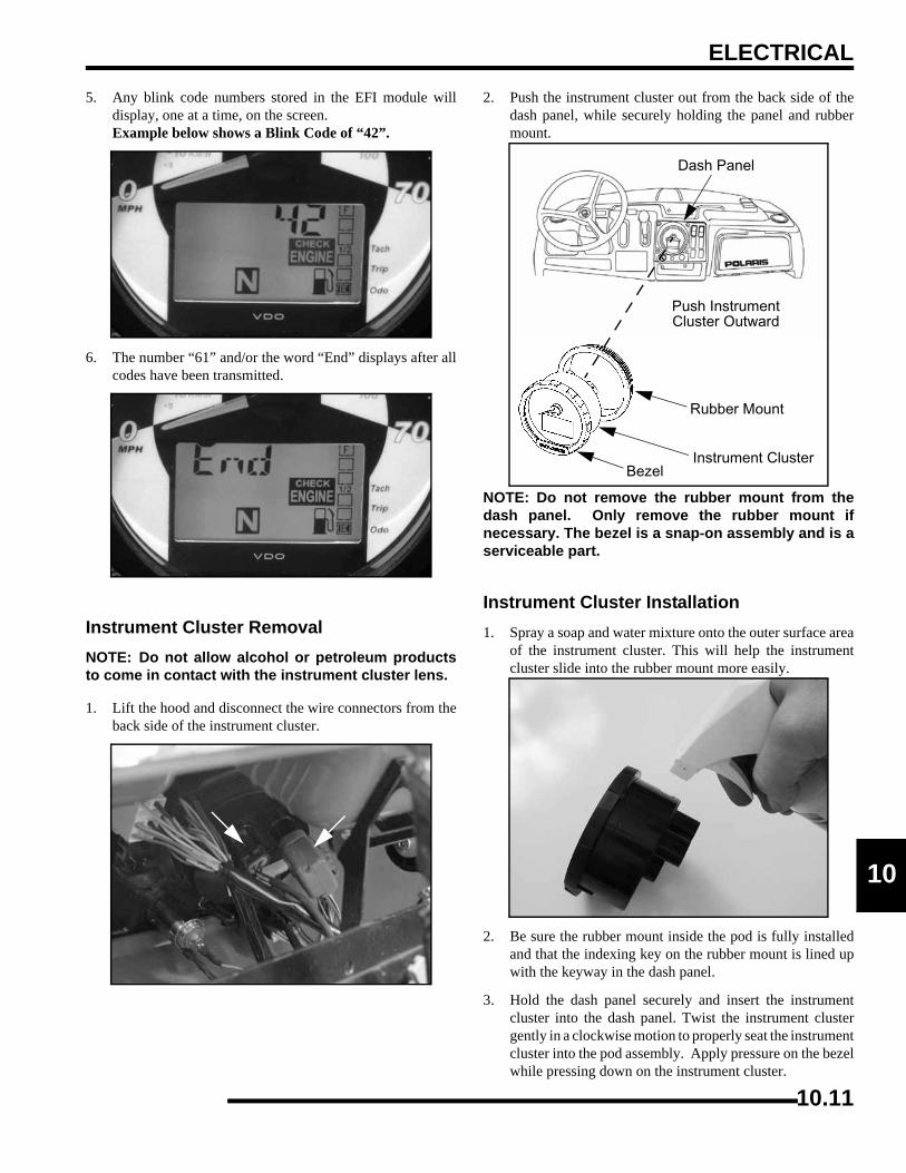
ELECTRICAL
0
15. Any blink code numbers stored in the EFI module willdisplay, one at a time, on the screen.Example below shows a Blink Code of “42”.
6. The number “61” and/or the word “End” displays after allcodes have been transmitted.
Instrument Cluster RemovalNOTE: Do not allow alcohol or petroleum productsto come in contact with the instrument cluster lens.
1. Lift the hood and disconnect the wire connectors from theback side of the instrument cluster.
2. Push the instrument cluster out from the back side of thedash panel, while securely holding the panel and rubbermount.
NOTE: Do not remove the rubber mount from thedash panel. Only remove the rubber mount ifnecessary. The bezel is a snap-on assembly and is aserviceable part.
Instrument Cluster Installation1. Spray a soap and water mixture onto the outer surface area
of the instrument cluster. This will help the instrumentcluster slide into the rubber mount more easily.
2. Be sure the rubber mount inside the pod is fully installedand that the indexing key on the rubber mount is lined upwith the keyway in the dash panel.
3. Hold the dash panel securely and insert the instrumentcluster into the dash panel. Twist the instrument clustergently in a clockwise motion to properly seat the instrumentcluster into the pod assembly. Apply pressure on the bezelwhile pressing down on the instrument cluster.
Rubber Mount
Instrument ClusterBezel
Push InstrumentCluster Outward
Dash Panel
10.11
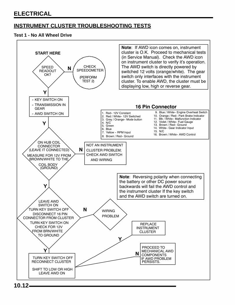
ELECTRICAL
INSTRUMENT CLUSTER TROUBLESHOOTING TESTSTest 1 - No All Wheel Drive
10.12
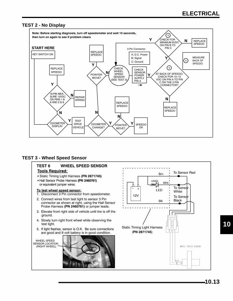
ELECTRICAL
0
1TEST 2 - No Display
TEST 3 - Wheel Speed Sensor
10.13
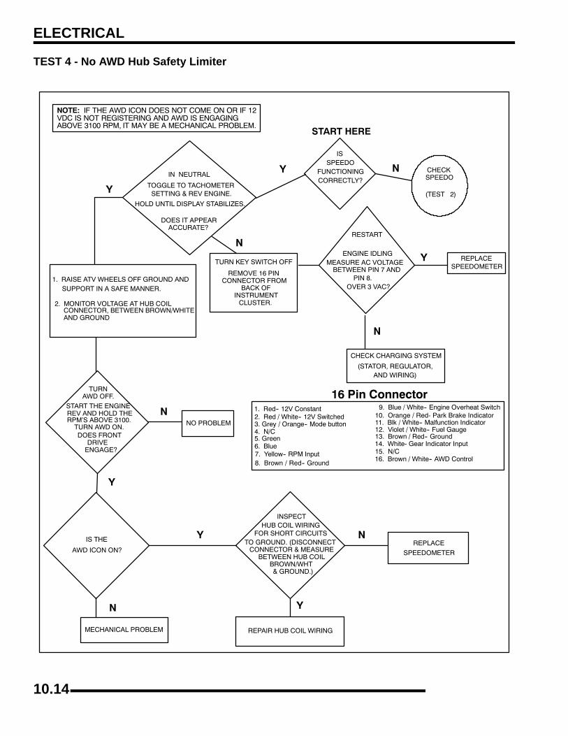
ELECTRICAL
TEST 4 - No AWD Hub Safety Limiter
10.14
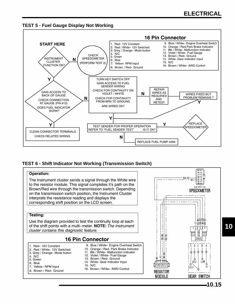
ELECTRICAL
0
1TEST 5 - Fuel Gauge Display Not Working
TEST 6 - Shift Indicator Not Working (Transmission Switch)
10.15

ELECTRICAL
ALL WHEEL DRIVE (AWD) COILOperation Overview
• When the AWD switch is “ON”, 12 VDC power is present at the hub coil.
• If the criteria is met, the instrument cluster provides a ground path at pin #16. When this occurs the AWD icon should display in the instrument cluster.
• The AWD system must be grounded to operate.
Diagnosing System Failures• Verify the AWD switch is functional and that a
minimum of 11 volts is present at the hub coil.
• Verify the AWD hub coil is functional. Test the AWD hub coil using an ohm meter. See specifications below.
• Verify the wiring harness, wiring, connectors, connector pins and grounds are undamaged, clean and connect properly.
• Verify continuity of wire connections with a known good volt/ohm meter.
IMPORTANT: Verify all wires and wiring connectionshave been tested properly with a known good volt/ohm meter before suspecting a component failure.80% of all electrical issues are caused by bad/failedconnections and grounds.
GEAR POSITION INDICATOR SWITCHTest Diagram
AWD Hub Coil Resistance:24 Ω ± 5%
NOTE: Also see “INSTRUMENT CLUSTER TROUBLESHOOTING” for switch circuit.
TRANSMISSION SWITCH
High / Low / Neutral / Reverse Switch
High Range Low Range Neutral Reverse
VioletGreen/White Brown/Red
White/BlueBlue/Red
10.16
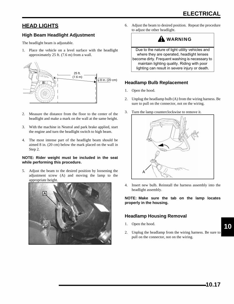
ELECTRICAL
0
1HEAD LIGHTSHigh Beam Headlight AdjustmentThe headlight beam is adjustable.
1. Place the vehicle on a level surface with the headlightapproximately 25 ft. (7.6 m) from a wall.
2. Measure the distance from the floor to the center of theheadlight and make a mark on the wall at the same height.
3. With the machine in Neutral and park brake applied, startthe engine and turn the headlight switch to high beam.
4. The most intense part of the headlight beam should beaimed 8 in. (20 cm) below the mark placed on the wall inStep 2.
NOTE: Rider weight must be included in the seatwhile performing this procedure.
5. Adjust the beam to the desired position by loosening theadjustment screw (A) and moving the lamp to theappropriate height.
6. Adjust the beam to desired position. Repeat the procedureto adjust the other headlight.
Headlamp Bulb Replacement1. Open the hood.
2. Unplug the headlamp bulb (A) from the wiring harness. Besure to pull on the connector, not on the wiring.
3. Turn the lamp counterclockwise to remove it.
4. Insert new bulb. Reinstall the harness assembly into theheadlight assembly.
NOTE: Make sure the tab on the lamp locatesproperly in the housing.
Headlamp Housing Removal1. Open the hood.
2. Unplug the headlamp from the wiring harness. Be sure topull on the connector, not on the wiring.
XX
25 ft.(7.6 m)
8 in. (20 cm)
A
WARNING
Due to the nature of light utility vehicles and where they are operated, headlight lenses
become dirty. Frequent washing is necessary to maintain lighting quality. Riding with poor
lighting can result in severe injury or death.
A
10.17
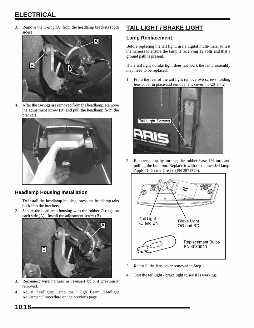
ELECTRICAL
3. Remove the O-ring (A) from the headlamp brackets (bothsides)
4. After the O-rings are removed from the headlamp, Removethe adjustment screw (B) and pull the headlamp from thebrackets.
Headlamp Housing Installation1. To install the headlamp housing, press the headlamp tabs
back into the brackets.2. Secure the headlamp housing with the rubber O-rings on
each side (A). Install the adjustment screw (B).
3. Reconnect wire harness or re-insert bulb if previouslyremoved.
4. Adjust headlights using the “High Beam HeadlightAdjustment” procedure on the previous page.
TAIL LIGHT / BRAKE LIGHTLamp ReplacementBefore replacing the tail light, use a digital multi-meter to testthe harness to ensure the lamp is receiving 12 volts and that aground path is present.
If the tail light / brake light does not work the lamp assemblymay need to be replaced.
1. From the rear of the tail light remove two screws holdinglens cover in place and remove lens cover. (T-20 Torx)
2. Remove lamp by turning the rubber base 1/4 turn andpulling the bulb out. Replace it with recommended lamp.Apply Dielectric Grease (PN 2871329).
3. Reinstall the lens cover removed in Step 1.
4. Test the tail light / brake light to see it is working.
A
B
B
A
Tail Light Screws
Tail LightBrake LightOG and RD
RD and BN
Replacement BulbsPN 4030040
10.18
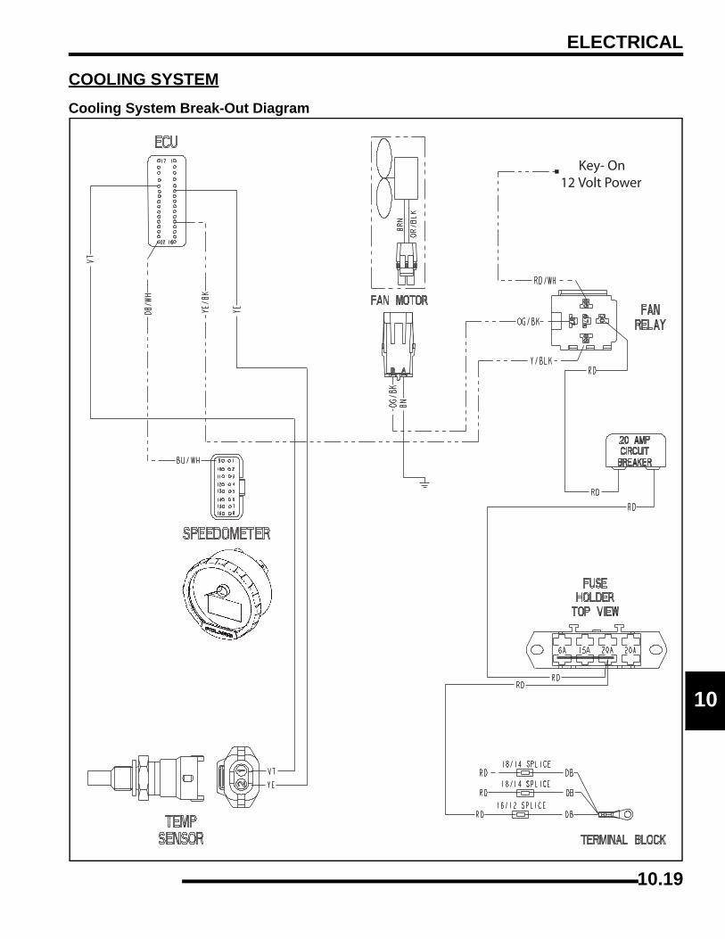
ELECTRICAL
0
1COOLING SYSTEMCooling System Break-Out Diagram
10.19
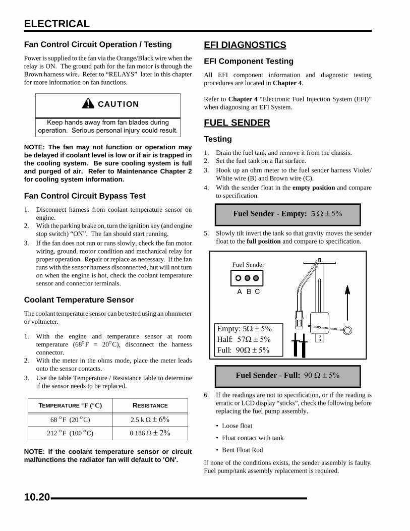
ELECTRICAL
Fan Control Circuit Operation / TestingPower is supplied to the fan via the Orange/Black wire when therelay is ON. The ground path for the fan motor is through theBrown harness wire. Refer to “RELAYS” later in this chapterfor more information on fan functions.
NOTE: The fan may not function or operation maybe delayed if coolant level is low or if air is trapped inthe cooling system. Be sure cooling system is fulland purged of air. Refer to Maintenance Chapter 2for cooling system information.
Fan Control Circuit Bypass Test1. Disconnect harness from coolant temperature sensor on
engine.2. With the parking brake on, turn the ignition key (and engine
stop switch) “ON”. The fan should start running.3. If the fan does not run or runs slowly, check the fan motor
wiring, ground, motor condition and mechanical relay forproper operation. Repair or replace as necessary. If the fanruns with the sensor harness disconnected, but will not turnon when the engine is hot, check the coolant temperaturesensor and connector terminals.
Coolant Temperature SensorThe coolant temperature sensor can be tested using an ohmmeteror voltmeter.
1. With the engine and temperature sensor at roomtemperature (68°F = 20°C), disconnect the harnessconnector.
2. With the meter in the ohms mode, place the meter leadsonto the sensor contacts.
3. Use the table Temperature / Resistance table to determineif the sensor needs to be replaced.
NOTE: If the coolant temperature sensor or circuitmalfunctions the radiator fan will default to 'ON'.
EFI DIAGNOSTICSEFI Component TestingAll EFI component information and diagnostic testingprocedures are located in Chapter 4.
Refer to Chapter 4 “Electronic Fuel Injection System (EFI)”when diagnosing an EFI System.
FUEL SENDERTesting1. Drain the fuel tank and remove it from the chassis.2. Set the fuel tank on a flat surface.3. Hook up an ohm meter to the fuel sender harness Violet/
White wire (B) and Brown wire (C).4. With the sender float in the empty position and compare
to specification.
5. Slowly tilt invert the tank so that gravity moves the senderfloat to the full position and compare to specification.
6. If the readings are not to specification, or if the reading iserratic or LCD display “sticks”, check the following beforereplacing the fuel pump assembly.
• Loose float
• Float contact with tank
• Bent Float Rod
If none of the conditions exists, the sender assembly is faulty.Fuel pump/tank assembly replacement is required.
CAUTION
Keep hands away from fan blades during operation. Serious personal injury could result.
TEMPERATURE °F (°C) RESISTANCE
68 °F (20 °C) 2.5 k Ω ± 6%
212 °F (100 °C) 0.186 Ω ± 2%
Fuel Sender - Empty: 5 Ω ± 5%
Fuel Sender - Full: 90 Ω ± 5%
Fuel Sender
Empty: 5Ω ± 5% Half: 57Ω ± 5% Full: 90Ω ± 5%
10.20
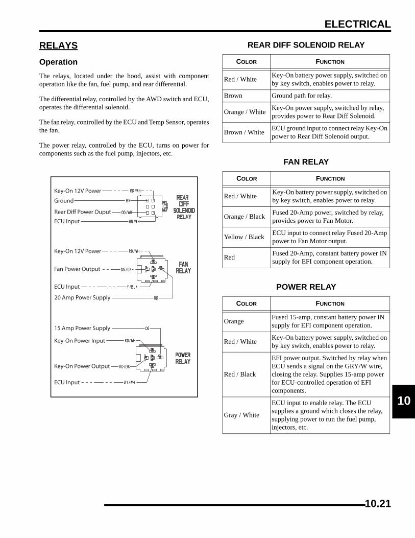
ELECTRICAL
0
1RELAYSOperationThe relays, located under the hood, assist with componentoperation like the fan, fuel pump, and rear differential.
The differential relay, controlled by the AWD switch and ECU,operates the differential solenoid.
The fan relay, controlled by the ECU and Temp Sensor, operatesthe fan.
The power relay, controlled by the ECU, turns on power forcomponents such as the fuel pump, injectors, etc.
REAR DIFF SOLENOID RELAY
COLOR FUNCTION
Red / White Key-On battery power supply, switched on by key switch, enables power to relay.
Brown Ground path for relay.
Orange / White Key-On power supply, switched by relay, provides power to Rear Diff Solenoid.
Brown / White ECU ground input to connect relay Key-On power to Rear Diff Solenoid output.
FAN RELAY
COLOR FUNCTION
Red / White Key-On battery power supply, switched on by key switch, enables power to relay.
Orange / Black Fused 20-Amp power, switched by relay, provides power to Fan Motor.
Yellow / Black ECU input to connect relay Fused 20-Amp power to Fan Motor output.
Red Fused 20-Amp, constant battery power IN supply for EFI component operation.
POWER RELAY
COLOR FUNCTION
Orange Fused 15-amp, constant battery power IN supply for EFI component operation.
Red / White Key-On battery power supply, switched on by key switch, enables power to relay.
Red / Black
EFI power output. Switched by relay when ECU sends a signal on the GRY/W wire, closing the relay. Supplies 15-amp power for ECU-controlled operation of EFI components.
Gray / White
ECU input to enable relay. The ECU supplies a ground which closes the relay, supplying power to run the fuel pump, injectors, etc.
10.21
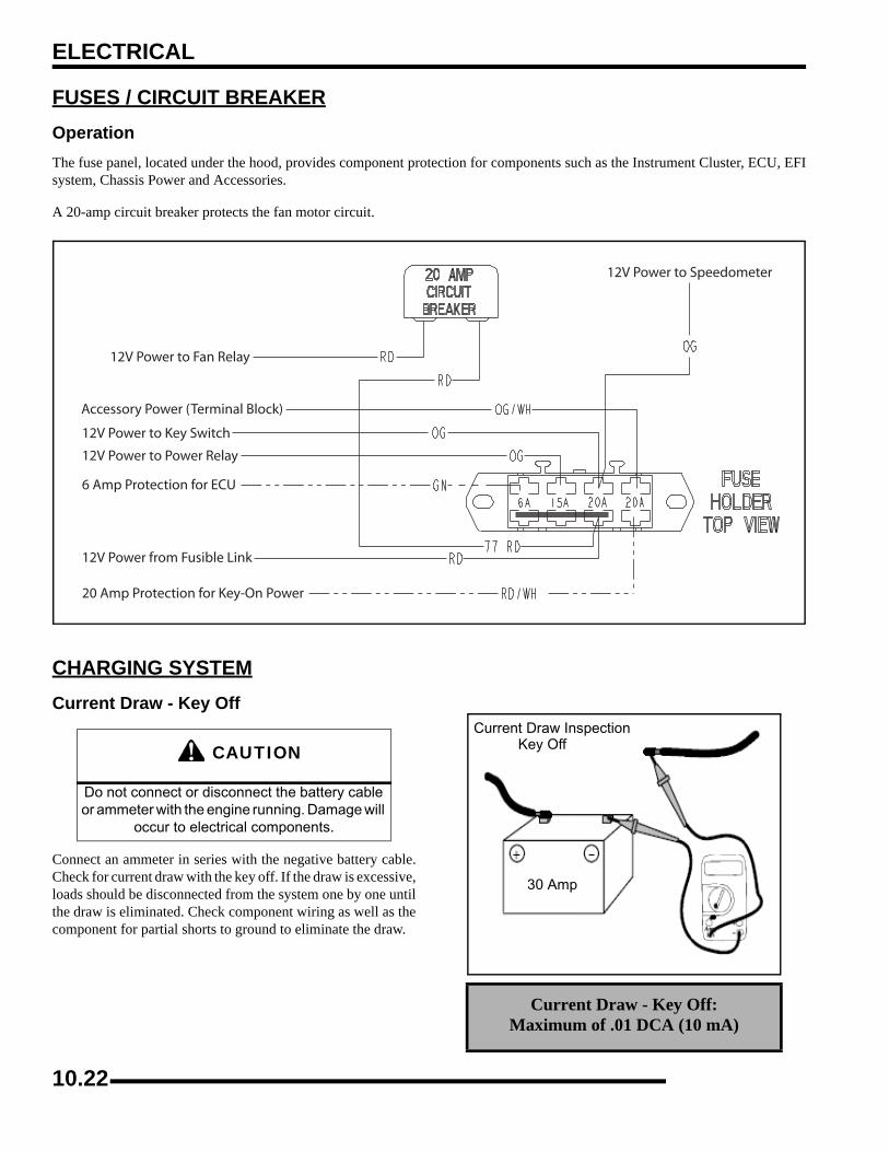
ELECTRICAL
FUSES / CIRCUIT BREAKEROperationThe fuse panel, located under the hood, provides component protection for components such as the Instrument Cluster, ECU, EFIsystem, Chassis Power and Accessories.
A 20-amp circuit breaker protects the fan motor circuit.
CHARGING SYSTEMCurrent Draw - Key Off
Connect an ammeter in series with the negative battery cable.Check for current draw with the key off. If the draw is excessive,loads should be disconnected from the system one by one untilthe draw is eliminated. Check component wiring as well as thecomponent for partial shorts to ground to eliminate the draw.
CAUTION
Do not connect or disconnect the battery cable or ammeter with the engine running. Damage will
occur to electrical components.
Current Draw - Key Off:Maximum of .01 DCA (10 mA)
Current Draw Inspection Key Off
30 Amp
10.22
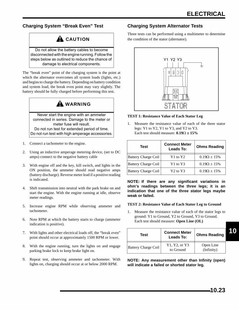
ELECTRICAL
0
1Charging System “Break Even” Test
The “break even” point of the charging system is the point atwhich the alternator overcomes all system loads (lights, etc.)and begins to charge the battery. Depending on battery conditionand system load, the break even point may vary slightly. Thebattery should be fully charged before performing this test.
1. Connect a tachometer to the engine.
2. Using an inductive amperage metering device, (set to DCamps) connect to the negative battery cable
3. With engine off and the key, kill switch, and lights in theON position, the ammeter should read negative amps(battery discharge). Reverse meter lead if a positive readingis indicated.
4. Shift transmission into neutral with the park brake on andstart the engine. With the engine running at idle, observemeter readings.
5. Increase engine RPM while observing ammeter andtachometer.
6. Note RPM at which the battery starts to charge (ammeterindication is positive).
7. With lights and other electrical loads off, the “break even”point should occur at approximately 1500 RPM or lower.
8. With the engine running, turn the lights on and engageparking brake lock to keep brake light on.
9. Repeat test, observing ammeter and tachometer. Withlights on, charging should occur at or below 2000 RPM.
Charging System Alternator TestsThree tests can be performed using a multimeter to determinethe condition of the stator (alternator).
TEST 1: Resistance Value of Each Stator Leg
1. Measure the resistance value of each of the three statorlegs: Y1 to Y2, Y1 to Y3, and Y2 to Y3.Each test should measure: 0.19Ω ± 15%
NOTE: If there are any significant variations inohm’s readings between the three legs; it is anindication that one of the three stator legs maybeweak or failed.
TEST 2: Resistance Value of Each Stator Leg to Ground
1. Measure the resistance value of each of the stator legs toground: Y1 to Ground, Y2 to Ground, Y3 to Ground.Each test should measure: Open Line (OL)
NOTE: Any measurement other than Infinity (open)will indicate a failed or shorted stator leg.
CAUTION
Do not allow the battery cables to become disconnected with the engine running. Follow the steps below as outlined to reduce the chance of
damage to electrical components.
WARNING
Never start the engine with an ammeter connected in series. Damage to the meter or
meter fuse will result. Do not run test for extended period of time.
Do not run test with high amperage accessories.
Test Connect Meter Leads To: Ohms Reading
Battery Charge Coil Y1 to Y2 0.19Ω ± 15%
Battery Charge Coil Y1 to Y3 0.19Ω ± 15%
Battery Charge Coil Y2 to Y3 0.19Ω ± 15%
Test Connect Meter Leads To: Ohms Reading
Battery Charge Coil Y1, Y2, or Y3 to Ground
Open Line (Infinity)
Y1 Y2 Y3
10.23
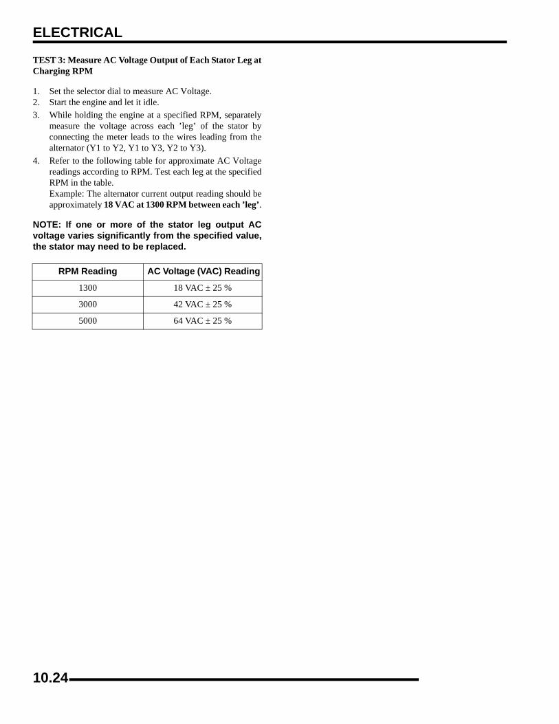
ELECTRICAL
TEST 3: Measure AC Voltage Output of Each Stator Leg atCharging RPM
1. Set the selector dial to measure AC Voltage.2. Start the engine and let it idle.3. While holding the engine at a specified RPM, separately
measure the voltage across each ’leg’ of the stator byconnecting the meter leads to the wires leading from thealternator (Y1 to Y2, Y1 to Y3, Y2 to Y3).
4. Refer to the following table for approximate AC Voltagereadings according to RPM. Test each leg at the specifiedRPM in the table.Example: The alternator current output reading should beapproximately 18 VAC at 1300 RPM between each ’leg’.
NOTE: If one or more of the stator leg output ACvoltage varies significantly from the specified value,the stator may need to be replaced.
RPM Reading AC Voltage (VAC) Reading
1300 18 VAC ± 25 %
3000 42 VAC ± 25 %
5000 64 VAC ± 25 %
10.24

ELECTRICAL
0
1Charging System Testing Flow ChartWhenever charging system problems are suspected, proceed with the following system check after verifying that all wires are in goodcondition, connected and not exposed or pinched.:
Using a multitester set on D.C. volts, mea-sure the battery open circuit voltage (Seeearlier test). It should be 12.4 volts or more. Is it?
Meter Setting: DC VoltsWith the transmission in Neutral, start the
Meter Setting: DC AmpsPerform system “Break Even Amperage”
Meter Setting: DC VoltsReconnect the alternator wires. Note: Redwire must be connected to harness. Batteryvoltage must be present on red wire terminalon harness side of voltage regulator connector.
Is voltage present?
If all of the previous tests indicate a good
Yes
No
No
Yes
Yes
Remove the battery and properly ser-vice. Reinstall the fully charged batteryor a fully charged shop battery.
No
Check Key off Current Draw. Yes
Check for owner modification, anddiscuss operating habits. The batterywill continually discharge if operatedbelow the “Break Even” RPM. Con-tinued problems would call for battery inspection.
Yes
Inspect the wiring harness betweenthe panel and the stator for remove the recoil and flywheel.Inspect the flywheel magnets, statorcoils and stator wires for damage.
No
Check stator, regulator, ground, batteryand battery connections. Also checkwire connections and wire condition.Repair or replace faulty wiring or
No
engine and increase RPM to between 3000
test outlined in this chapter.
Does charging occur as specified?
Ohm stator wires, if bad replace stator, if good,continue with alternator output test.
Meter Setting: AC VoltsDisconnect the Yellow wires from the regulator /rectifier. Using a multitester, perform an Alternator Output test. See test procedure on Page 10.24.
damage. If no damage is found,
Repair or replace any damaged components.
components.
and 4000. Read battery voltage with the multitester. Readings should increase to between 13.0 and 14.6 V D.C.Are they?
Does output meet specification?
condition, but the charging voltage does not rise above battery voltage at the connector or wire harness, replace the voltage regulator.
10.25
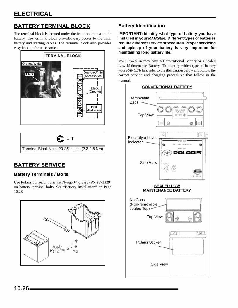
ELECTRICAL
BATTERY TERMINAL BLOCKThe terminal block is located under the front hood next to thebattery. The terminal block provides easy access to the mainbattery and starting cables. The terminal block also provideseasy hookup for accessories.
BATTERY SERVICEBattery Terminals / BoltsUse Polaris corrosion resistant Nyogel™ grease (PN 2871329)on battery terminal bolts. See “Battery Installation” on Page10.28.
Battery IdentificationIMPORTANT: Identify what type of battery you haveinstalled in your RANGER. Different types of batteriesrequire different service procedures. Proper servicingand upkeep of your battery is very important formaintaining long battery life.
Your RANGER may have a Conventional Battery or a SealedLow Maintenance Battery. To identify which type of batteryyour RANGER has, refer to the illustration below and follow thecorrect service and charging procedures that follow in themanual.
= T
Terminal Block Nuts: 20-25 in. lbs. (2.3-2.8 Nm)
TERMINAL BLOCK
Orange/White
Black
Red
Orange/White(Accessories)
Black(Ground)
Red(Battery+)
ApplyNyogel™
CONVENTIONAL BATTERY
Top View
Electrolyte Level
Side View
SEALED LOWMAINTENANCE BATTERY
No Caps(Non-removablesealed Top)
Top View
Side View
Polaris Sticker
RemovableCaps
Indicator
10.26

ELECTRICAL
0
1CONVENTIONAL BATTERYBattery Activation
To ensure maximum service life and performance from a newbattery, perform the following steps. NOTE: Do not service thebattery unless it will be put into regular service within 30 days.After initial service, add only distilled water to the battery.Never add electrolyte after a battery has been in service.
NOTE: New Battery: Battery must be fully chargedbefore use or battery life will be significantlyreduced 10-30% of the battery’s full potential.
To activate a new battery:
1. Remove vent plug from vent fitting. Remove cell caps.2. Fill battery with electrolyte to upper level marks on case.3. Set battery aside to allow for acid absorption and
stabilization for 30 minutes.
4. Add electrolyte to bring level back to upper level mark oncase.
NOTE: This is the last time that electrolyte shouldbe added. If the level becomes low after this point,add only distilled water.
5. Charge battery at 1/10 of its amp/hour rating. Examples: 1/10 of 9 amp battery = .9 amp; 1/10 of 14 amp battery = 1.4amp; 1/10 of 18 amp battery = 1.8 amp (recommendedcharging rates).
6. Check specific gravity of each cell with a hydrometer toassure each has a reading of 1.270 or higher.
Battery InspectionThe battery is located under the hood.
Inspect the battery fluid level. When the battery fluid nears thelower level, remove the battery and fill with distilled water onlyto the upper level line. To remove the battery:
WARNING
Battery electrolyte is poisonous. It contains sulfuric acid. Serious burns can result from contact with skin, eyes or clothing. Antidote:
External: Flush with water.
Internal: Drink large quantities of water or milk. Follow with milk of magnesia, beaten egg, or
vegetable oil. Call physician immediately.
Eyes: Flush with water for 15 minutes and get prompt medical attention.
Batteries produce explosive gases. Keep sparks, flame, cigarettes etc. away. Ventilate when charging or using in an enclosed space.
Always shield eyes when working near batteries.
KEEP OUT OF REACH OF CHILDREN.
WARNING
The gases given off by a battery are explosive. Any spark or open flame near a battery can
cause an explosion which will spray battery acid on anyone close to it. Should there be contact with battery acid, wash the affected area with
large quantities of cool water and seek immediate medical attention. Maintain
between upperand lower levelmarks
10.27
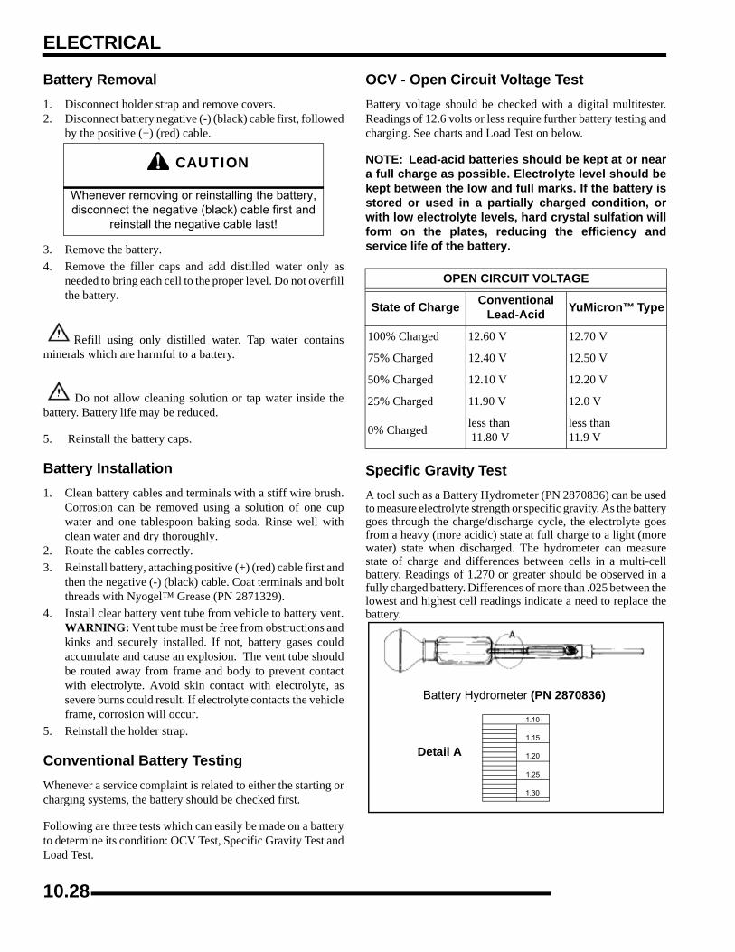
ELECTRICAL
Battery Removal1. Disconnect holder strap and remove covers.2. Disconnect battery negative (-) (black) cable first, followed
by the positive (+) (red) cable.
3. Remove the battery.4. Remove the filler caps and add distilled water only as
needed to bring each cell to the proper level. Do not overfillthe battery.
Refill using only distilled water. Tap water containsminerals which are harmful to a battery.
Do not allow cleaning solution or tap water inside thebattery. Battery life may be reduced.
5. Reinstall the battery caps.
Battery Installation1. Clean battery cables and terminals with a stiff wire brush.
Corrosion can be removed using a solution of one cupwater and one tablespoon baking soda. Rinse well withclean water and dry thoroughly.
2. Route the cables correctly.3. Reinstall battery, attaching positive (+) (red) cable first and
then the negative (-) (black) cable. Coat terminals and boltthreads with Nyogel™ Grease (PN 2871329).
4. Install clear battery vent tube from vehicle to battery vent.WARNING: Vent tube must be free from obstructions andkinks and securely installed. If not, battery gases couldaccumulate and cause an explosion. The vent tube shouldbe routed away from frame and body to prevent contactwith electrolyte. Avoid skin contact with electrolyte, assevere burns could result. If electrolyte contacts the vehicleframe, corrosion will occur.
5. Reinstall the holder strap.
Conventional Battery TestingWhenever a service complaint is related to either the starting orcharging systems, the battery should be checked first.
Following are three tests which can easily be made on a batteryto determine its condition: OCV Test, Specific Gravity Test andLoad Test.
OCV - Open Circuit Voltage TestBattery voltage should be checked with a digital multitester.Readings of 12.6 volts or less require further battery testing andcharging. See charts and Load Test on below.
NOTE: Lead-acid batteries should be kept at or neara full charge as possible. Electrolyte level should bekept between the low and full marks. If the battery isstored or used in a partially charged condition, orwith low electrolyte levels, hard crystal sulfation willform on the plates, reducing the efficiency andservice life of the battery.
Specific Gravity TestA tool such as a Battery Hydrometer (PN 2870836) can be usedto measure electrolyte strength or specific gravity. As the batterygoes through the charge/discharge cycle, the electrolyte goesfrom a heavy (more acidic) state at full charge to a light (morewater) state when discharged. The hydrometer can measurestate of charge and differences between cells in a multi-cellbattery. Readings of 1.270 or greater should be observed in afully charged battery. Differences of more than .025 between thelowest and highest cell readings indicate a need to replace thebattery.
CAUTION
Whenever removing or reinstalling the battery, disconnect the negative (black) cable first and
reinstall the negative cable last!
OPEN CIRCUIT VOLTAGE
State of Charge Conventional Lead-Acid YuMicron™ Type
100% Charged 12.60 V 12.70 V
75% Charged 12.40 V 12.50 V
50% Charged 12.10 V 12.20 V
25% Charged 11.90 V 12.0 V
0% Charged less than 11.80 V
less than 11.9 V
1.10
1.15
1.20
1.25
1.30
Detail A
Battery Hydrometer (PN 2870836)
10.28
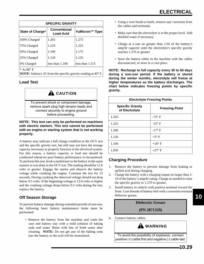
ELECTRICAL
0
1Load Test
NOTE: This test can only be performed on machineswith electric starters. This test cannot be performedwith an engine or starting system that is not workingproperly.
A battery may indicate a full charge condition in the OCV testand the specific gravity test, but still may not have the storagecapacity necessary to properly function in the electrical system.For this reason, a battery capacity or load test should beconducted whenever poor battery performance is encountered.To perform this test, hook a multitester to the battery in the samemanner as was done in the OCV test. The reading should be 12.6volts or greater. Engage the starter and observe the batteryvoltage while cranking the engine. Continue the test for 15seconds. During cranking the observed voltage should not dropbelow 9.5 volts. If the beginning voltage is 12.6 volts or higherand the cranking voltage drops below 9.5 volts during the test,replace the battery.
Off Season StorageTo prevent battery damage during extended periods of non-use,the following basic battery maintenance items must beperformed:
• Remove the battery from the machine and wash thecase and battery tray with a mild solution of bakingsoda and water. Rinse with lots of fresh water aftercleaning. NOTE: Do not get any of the baking sodainto the battery or the acid will be neutralized.
• Using a wire brush or knife, remove any corrosion fromthe cables and terminals.
• Make sure that the electrolyte is at the proper level. Adddistilled water if necessary.
• Charge at a rate no greater than 1/10 of the battery’samp/hr capacity until the electrolyte’s specific gravityreaches 1.270 or greater.
• Store the battery either in the machine with the cablesdisconnected, or store in a cool place.
NOTE: Recharge to full capacity every 30 to 60 daysduring a non-use period. If the battery is storedduring the winter months, electrolyte will freeze athigher temperatures as the battery discharges. Thechart below indicates freezing points by specificgravity.
Charging Procedure1. Remove the battery to prevent damage from leaking or
spilled acid during charging.2. Charge the battery with a charging output no larger than 1/
10 of the battery’s amp/hr rating. Charge as needed to raisethe specific gravity to 1.270 or greater.
3. Install battery in vehicle with positive terminal toward thefront. Coat threads of battery bolt with a corrosion resistantdielectric grease.
4. Connect battery cables.
SPECIFIC GRAVITY
State of Charge* Conventional Lead-Acid YuMicron™ Type
100% Charged 1.265 1.275
75% Charged 1.210 1.225
50% Charged 1.160 1.175
25% Charged 1.120 1.135
0% Charged less than 1.100 less than 1.115
* At 80° FNOTE: Subtract .01 from the specific gravity reading at 40° F.
CAUTION
To prevent shock or component damage, remove spark plug high tension leads and
connect securely to engine ground before proceeding.
Electrolyte Freezing Points
Specific Gravityof Electrolyte Freezing Point
1.265 -75° F
1.225 -35° F
1.200 -17° F
1.150 +5° F
1.100 +18° F
1.050 +27° F
Dielectric Grease
(PN 2871329)
WARNING
To avoid the possibility of explosion, connect positive (+) cable first and negative (-) cable last.
10.29

ELECTRICAL
5. After connecting the battery cables, install the cover on thebattery and attach the hold down strap.
6. Install clear battery vent tube from vehicle to battery vent.WARNING: Vent tube must be free from obstructions andkinks and securely installed. If not, battery gases couldaccumulate and cause an explosion. Vent should be routedaway from frame and body to prevent contact withelectrolyte. Avoid skin contact with electrolyte, as severeburns could result. If electrolyte contacts the vehicle frame,corrosion will occur.
7. Route cables so they are tucked away in front and behindbattery.
LOW MAINTENANCE BATTERYBattery CheckNOTE: All Low Maintenance batteries are fullycharged and tested at the factory before installation.Expected shelf life varies upon storage conditions.As a general rule before placing the battery intoservice, check the battery condition and chargeaccordingly.
1. Check the date label on the side of the battery to calculatewhen to check voltage. The battery should be checkedevery 3 months.
2. Check the voltage with a voltmeter or multimeter. A fullycharged battery should be 12.8 V or higher.
3. If the voltage is below 12.8 V, the battery will need to berecharged.
Low Maintenance batteries are permanently sealed at the time ofmanufacture. The use of lead-calcium and AGM technologyinstead of lead-antimony allows the battery acid to be fullyabsorbed. For this reason, a Low Maintenance battery case isdark and the cell caps are not removable, since there is no needto check electrolyte level.
NOTE: New Batteries: Batteries must be fullycharged before use or battery life will be reduced by10-30% of full potential. Charge battery for 3-5 hoursat a current equivalent of 1/10 of the battery's ratedamp/hour capacity. Do not use the alternator tocharge a new battery. (Refer to Battery Activationand Maintenance video PN 9917987)
NEVER attempt to add electrolyte or water to a LowMaintenance battery. Doing so will damage the case and shortenthe life of the battery. Refer to the Battery Maintenance Video(PN 9917987) for proper instruction on servicing LowMaintenance batteries.
To service a Low Maintenance battery:
1. Remove battery from the vehicle.2. Test battery with a voltage meter or load tester to determine
battery condition. This will determine the length of timerequired to charge the battery to full capacity. Refer tocapacity table.
3. Charge battery using a variable rate charger.
Battery Inspection The battery is located under the front hood.
Battery Removal1. Remove the seat and remove battery holder strap.2. Disconnect battery negative (-) (black) cable first, followed
by the positive (+) (red) cable.
3. Remove the battery.
CAUTION
Whenever removing or reinstalling the battery, disconnect the negative (black) cable first and
reinstall the negative cable last!
Low Maintenance Batteryshown, but not used on
current RANGER Models
10.30
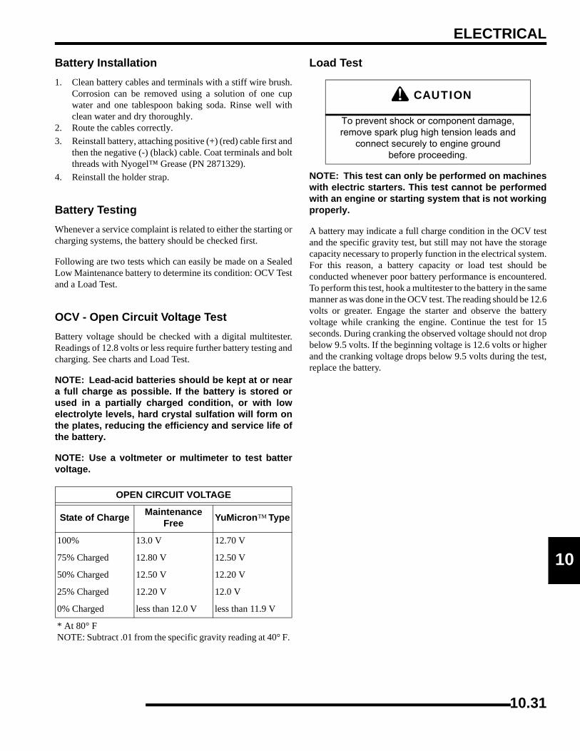
ELECTRICAL
0
1Battery Installation1. Clean battery cables and terminals with a stiff wire brush.
Corrosion can be removed using a solution of one cupwater and one tablespoon baking soda. Rinse well withclean water and dry thoroughly.
2. Route the cables correctly.3. Reinstall battery, attaching positive (+) (red) cable first and
then the negative (-) (black) cable. Coat terminals and boltthreads with Nyogel™ Grease (PN 2871329).
4. Reinstall the holder strap.
Battery TestingWhenever a service complaint is related to either the starting orcharging systems, the battery should be checked first.
Following are two tests which can easily be made on a SealedLow Maintenance battery to determine its condition: OCV Testand a Load Test.
OCV - Open Circuit Voltage TestBattery voltage should be checked with a digital multitester.Readings of 12.8 volts or less require further battery testing andcharging. See charts and Load Test.
NOTE: Lead-acid batteries should be kept at or neara full charge as possible. If the battery is stored orused in a partially charged condition, or with lowelectrolyte levels, hard crystal sulfation will form onthe plates, reducing the efficiency and service life ofthe battery.
NOTE: Use a voltmeter or multimeter to test battervoltage.
Load Test
NOTE: This test can only be performed on machineswith electric starters. This test cannot be performedwith an engine or starting system that is not workingproperly.
A battery may indicate a full charge condition in the OCV testand the specific gravity test, but still may not have the storagecapacity necessary to properly function in the electrical system.For this reason, a battery capacity or load test should beconducted whenever poor battery performance is encountered.To perform this test, hook a multitester to the battery in the samemanner as was done in the OCV test. The reading should be 12.6volts or greater. Engage the starter and observe the batteryvoltage while cranking the engine. Continue the test for 15seconds. During cranking the observed voltage should not dropbelow 9.5 volts. If the beginning voltage is 12.6 volts or higherand the cranking voltage drops below 9.5 volts during the test,replace the battery.
OPEN CIRCUIT VOLTAGE
State of Charge Maintenance Free YuMicron™ Type
100% 13.0 V 12.70 V
75% Charged 12.80 V 12.50 V
50% Charged 12.50 V 12.20 V
25% Charged 12.20 V 12.0 V
0% Charged less than 12.0 V less than 11.9 V
* At 80° FNOTE: Subtract .01 from the specific gravity reading at 40° F.
CAUTION
To prevent shock or component damage, remove spark plug high tension leads and
connect securely to engine ground before proceeding.
10.31

ELECTRICAL
Off-Season StorageTo prevent battery damage during extended periods of non-use,the following basic battery maintenance items must beperformed:
• Remove the battery from the machine and wash thecase and battery tray with a mild solution of bakingsoda and water. Rinse with lots of fresh water aftercleaning.
• Using a wire brush or knife, remove any corrosion fromthe cables and terminals.
• Charge at a rate no greater than 1/10 of the battery’samp/hr capacity.
• Store the battery either in the machine with the cablesdisconnected, or store in a cool place.
NOTE: Stored batteries lose their charge at the rateof 1% per day. Recharge to full capacity every 30 to60 days during a non-use period. If the battery isstored during the winter months, electrolyte willfreeze at higher temperatures as the batterydischarges. The chart below indicates freezingpoints by specific gravity.
Battery Charging If battery voltage is 12.8 V or less, the battery may needrecharging. When using an automatic charger, refer to thecharger manufacturer’s instructions for recharging. When usinga constant current charger, use the following guidelines forrecharging.
NOTE: Always verify battery condition before and 1-2 hours after the end of charging.
Battery Charging Reference Table
Electrolyte Freezing Points
Specific Gravityof Electrolyte Freezing Point
1.265 -75° F
1.225 -35° F
1.200 -17° F
1.150 +5° F
1.100 +18° F
1.050 +27° F
WARNINGAn overheated battery could explode, causing severe injury or death. Always watch charging
times carefully. Stop charging if the battery becomes very warm to the touch.
Allow it to cool before resuming charging.
State ofCharge Voltage Action Charge Time
100% 12.8-13 V
None, check voltage at 3 mos. after manufacture date
None Required
75-100% 12.5-12.8 V May need slight charge 3-6 hours
50-75% 12.0-12.5 V Needs Charge 5-11 hours
25-50% 11.5-12.0 V Needs ChargeAt least 13 hours, verify state of charge
0-25% 11.5 V or less Needs Charge At least 20 hours
WARNING
To avoid the possibility of sparks and explosion, connect positive (red) cable first and negative
(black) cable last.
10.32
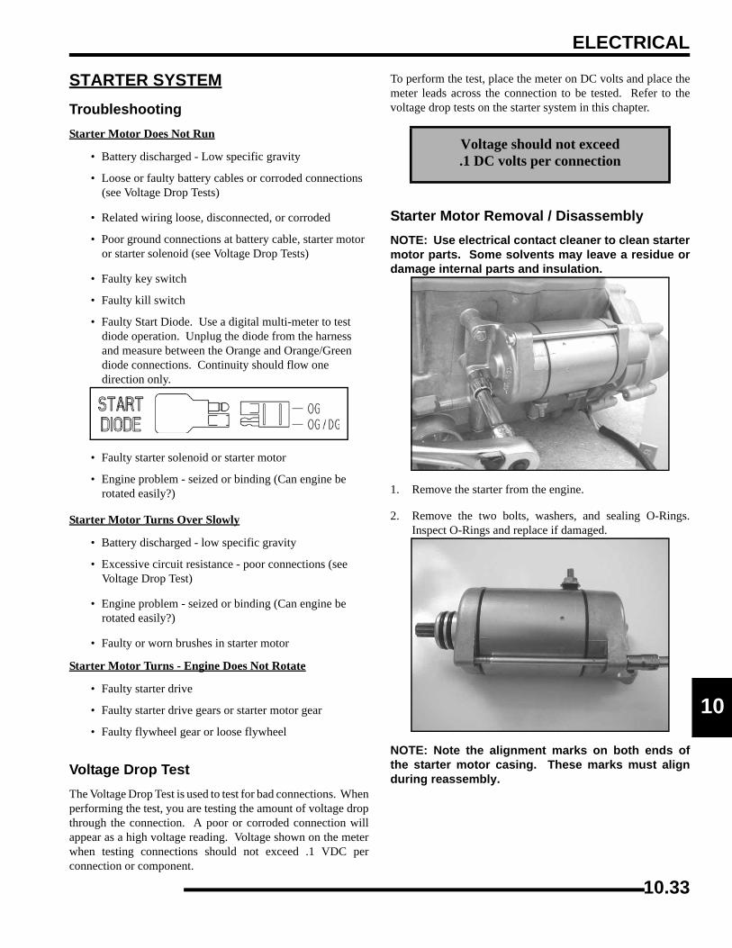
ELECTRICAL
0
1STARTER SYSTEMTroubleshootingStarter Motor Does Not Run
• Battery discharged - Low specific gravity
• Loose or faulty battery cables or corroded connections (see Voltage Drop Tests)
• Related wiring loose, disconnected, or corroded
• Poor ground connections at battery cable, starter motor or starter solenoid (see Voltage Drop Tests)
• Faulty key switch
• Faulty kill switch
• Faulty Start Diode. Use a digital multi-meter to test diode operation. Unplug the diode from the harness and measure between the Orange and Orange/Green diode connections. Continuity should flow one direction only.
• Faulty starter solenoid or starter motor
• Engine problem - seized or binding (Can engine be rotated easily?)
Starter Motor Turns Over Slowly
• Battery discharged - low specific gravity
• Excessive circuit resistance - poor connections (see Voltage Drop Test)
• Engine problem - seized or binding (Can engine be rotated easily?)
• Faulty or worn brushes in starter motor
Starter Motor Turns - Engine Does Not Rotate
• Faulty starter drive
• Faulty starter drive gears or starter motor gear
• Faulty flywheel gear or loose flywheel
Voltage Drop TestThe Voltage Drop Test is used to test for bad connections. Whenperforming the test, you are testing the amount of voltage dropthrough the connection. A poor or corroded connection willappear as a high voltage reading. Voltage shown on the meterwhen testing connections should not exceed .1 VDC perconnection or component.
To perform the test, place the meter on DC volts and place themeter leads across the connection to be tested. Refer to thevoltage drop tests on the starter system in this chapter.
Starter Motor Removal / DisassemblyNOTE: Use electrical contact cleaner to clean startermotor parts. Some solvents may leave a residue ordamage internal parts and insulation.
1. Remove the starter from the engine.
2. Remove the two bolts, washers, and sealing O-Rings.Inspect O-Rings and replace if damaged.
NOTE: Note the alignment marks on both ends ofthe starter motor casing. These marks must alignduring reassembly.
Voltage should not exceed.1 DC volts per connection
10.33
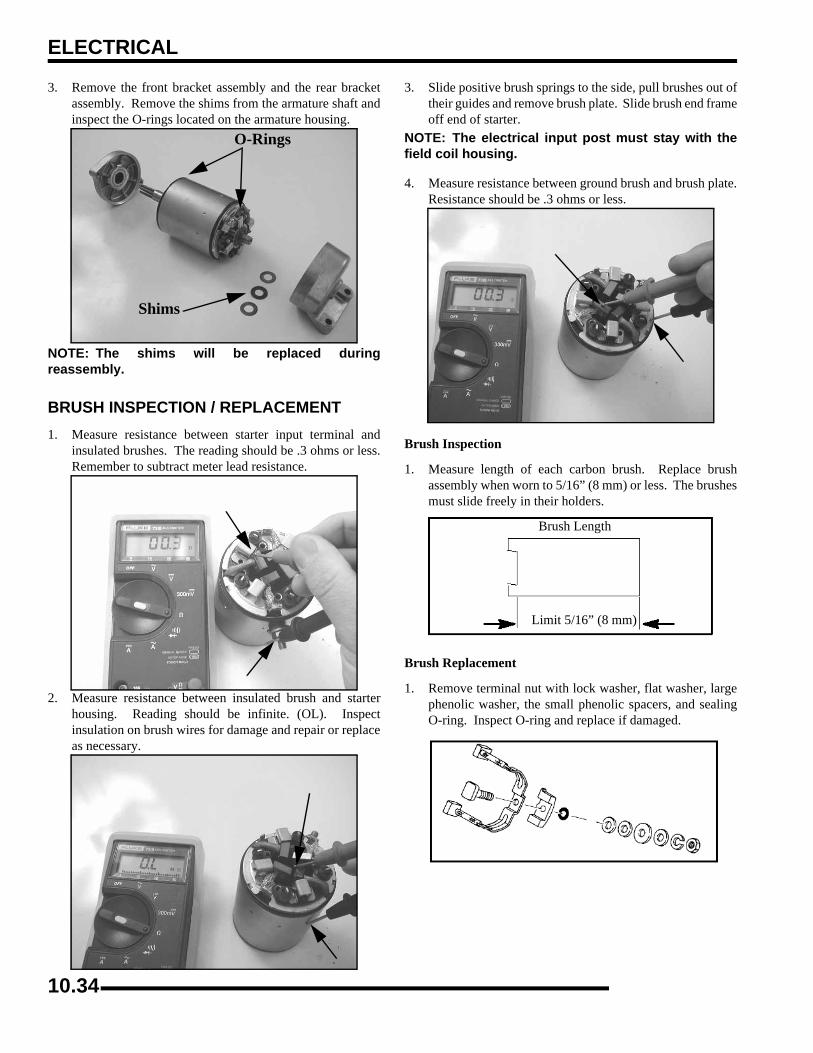
ELECTRICAL
3. Remove the front bracket assembly and the rear bracketassembly. Remove the shims from the armature shaft andinspect the O-rings located on the armature housing.
NOTE: The shims will be replaced duringreassembly.
BRUSH INSPECTION / REPLACEMENT1. Measure resistance between starter input terminal and
insulated brushes. The reading should be .3 ohms or less.Remember to subtract meter lead resistance.
2. Measure resistance between insulated brush and starterhousing. Reading should be infinite. (OL). Inspectinsulation on brush wires for damage and repair or replaceas necessary.
3. Slide positive brush springs to the side, pull brushes out oftheir guides and remove brush plate. Slide brush end frameoff end of starter.
NOTE: The electrical input post must stay with thefield coil housing.
4. Measure resistance between ground brush and brush plate.Resistance should be .3 ohms or less.
Brush Inspection
1. Measure length of each carbon brush. Replace brushassembly when worn to 5/16” (8 mm) or less. The brushesmust slide freely in their holders.
Brush Replacement
1. Remove terminal nut with lock washer, flat washer, largephenolic washer, the small phenolic spacers, and sealingO-ring. Inspect O-ring and replace if damaged.
O-Rings
Shims
Limit 5/16” (8 mm)
Brush Length
10.34

ELECTRICAL
0
12. Slide positive brush springs to the side, pull brushes out oftheir guides and remove brush plate.
Armature Testing1. Remove armature from starter casing. Note order of shims
on drive end for reassembly.
2. Inspect surface of commutator. Replace if excessivelyworn or damaged.
3. Using a digital multitester, measure the resistance betweeneach of the commutator segments. The reading should be.3 ohms or less.
4. Measure the resistance between each commutator segmentand the armature shaft. The reading should be infinite (nocontinuity).
5. Check commutator bars for discoloration. Bars discoloredin pairs indicate shorted coils, requiring replacement of thestarter motor.
6. Place armature in a growler. Turn growler on and positiona hacksaw blade or feeler gauge lengthwise 1/8” (.3 cm)above armature coil laminates. Rotate armature 360°. Ifhacksaw blade is drawn to armature on any pole, thearmature is shorted and must be replaced.
Starter Reassembly / Installation1. Install brush plate to field magnet housing aligning index
tab.
2. Install O-ring, two small phenolic spacers, large phenolicwasher, flat washer, lock washer, and terminal nut.
3. While holding brush springs away from brushes, pushbrushes back and hold in place.
4. Slide armature into field magnet housing. Release brushes.5. Lightly grease the drive roller bearing and reinstall drive
end frame on armature. Inspect seal for wear or damage.Replace drive end cap if necessary.
6. Be sure wire insulation is in place around positive brushwire and pushed completely into slot on phenolic plate.
CAUTION
Some cleaning solvents may damage the insulation in the starter. Care should be exercised when selecting an appropriate
solvent. If the commutator needs cleaning use only electrical contact cleaner.
CAUTION
Use care when handling starter housing. Do not drop or strike the housing as magnet damage is
possible. If magnets are damaged, starter must be replaced.
Roller Bearing
Seal
10.35
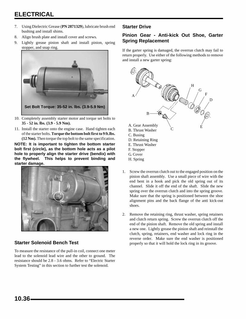
ELECTRICAL
7. Using Dielectric Grease (PN 2871329), lubricate brush endbushing and install shims.
8. Align brush plate and install cover and screws.9. Lightly grease pinion shaft and install pinion, spring
stopper, and snap ring.
10. Completely assembly starter motor and torque set bolts to35 - 52 in. lbs. (3.9 - 5.9 Nm).
11. Install the starter onto the engine case. Hand tighten eachof the starter bolts. Torque the bottom bolt first to 9 ft.lbs.(12 Nm). Then torque the top bolt to the same specification.
NOTE: It is important to tighten the bottom starterbolt first (circle), as the bottom hole acts as a pilothole to properly align the starter drive (bendix) withthe flywheel. This helps to prevent binding andstarter damage.
Starter Solenoid Bench TestTo measure the resistance of the pull-in coil, connect one meterlead to the solenoid lead wire and the other to ground. Theresistance should be 2.8 - 3.6 ohms. Refer to “Electric StarterSystem Testing” in this section to further test the solenoid.
Starter Drive
Pinion Gear - Anti-kick Out Shoe, GarterSpring Replacement
If the garter spring is damaged, the overrun clutch may fail toreturn properly. Use either of the following methods to removeand install a new garter spring:
1. Screw the overrun clutch out to the engaged position on thepinion shaft assembly. Use a small piece of wire with theend bent in a hook and pick the old spring out of itschannel. Slide it off the end of the shaft. Slide the newspring over the overrun clutch and into the spring groove.Make sure that the spring is positioned between the shoealignment pins and the back flange of the anti kick-outshoes.
2. Remove the retaining ring, thrust washer, spring retainersand clutch return spring. Screw the overrun clutch off theend of the pinion shaft. Remove the old spring and installa new one. Lightly grease the pinion shaft and reinstall theclutch, spring, retainers, end washer and lock ring in thereverse order. Make sure the end washer is positionedproperly so that it will hold the lock ring in its groove.
Set Bolt Torque: 35-52 in. lbs. (3.9-5.9 Nm)
A. Gear Assembly B. Thrust Washer C. Busing D. Retaining Ring E. Thrust Washer F. Stopper G. Cover H. Spring
A
B
C
D
E
FG
H
10.36

ELECTRICAL
0
1Starter Exploded View
1. Rubber Ring* 2. Brush Spring 3. Thrust Washer 4. Gear Assembly 5. O-Ring* 6. Brush Complete 7. O-Ring* 8. Thrust Washer 9. Shaft Complete
10. Gear Assembly 11. Through Bolt 12. Cover 13. Stopper 14. Snap Ring 15. Washer 16. Flange Bolt 17. Thrust Washer 18. Flange Bushing
* Indicates - Do not reuse. Replace with new parts.
10.37
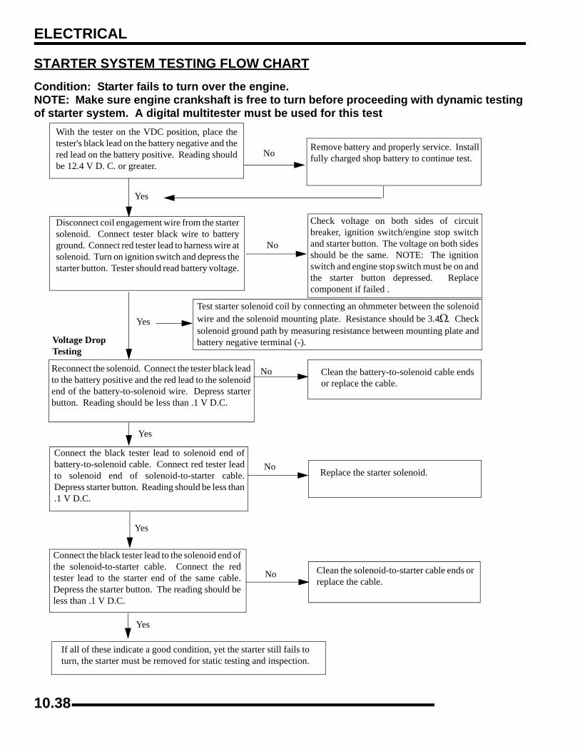
ELECTRICAL
STARTER SYSTEM TESTING FLOW CHARTCondition: Starter fails to turn over the engine. NOTE: Make sure engine crankshaft is free to turn before proceeding with dynamic testing of starter system. A digital multitester must be used for this test
With the tester on the VDC position, place thetester's black lead on the battery negative and thered lead on the battery positive. Reading shouldbe 12.4 V D. C. or greater.
Remove battery and properly service. Installfully charged shop battery to continue test.
Disconnect coil engagement wire from the startersolenoid. Connect tester black wire to batteryground. Connect red tester lead to harness wire atsolenoid. Turn on ignition switch and depress thestarter button. Tester should read battery voltage.
Check voltage on both sides of circuitbreaker, ignition switch/engine stop switchand starter button. The voltage on both sidesshould be the same. NOTE: The ignitionswitch and engine stop switch must be on andthe starter button depressed. Replacecomponent if failed .
Test starter solenoid coil by connecting an ohmmeter between the solenoidwire and the solenoid mounting plate. Resistance should be 3.4Ω. Checksolenoid ground path by measuring resistance between mounting plate andbattery negative terminal (-).
Reconnect the solenoid. Connect the tester black leadto the battery positive and the red lead to the solenoidend of the battery-to-solenoid wire. Depress starterbutton. Reading should be less than .1 V D.C.
Clean the battery-to-solenoid cable endsor replace the cable.
Connect the black tester lead to solenoid end ofbattery-to-solenoid cable. Connect red tester leadto solenoid end of solenoid-to-starter cable.Depress starter button. Reading should be less than.1 V D.C.
Replace the starter solenoid.
Connect the black tester lead to the solenoid end ofthe solenoid-to-starter cable. Connect the redtester lead to the starter end of the same cable.Depress the starter button. The reading should beless than .1 V D.C.
Clean the solenoid-to-starter cable ends orreplace the cable.
If all of these indicate a good condition, yet the starter still fails toturn, the starter must be removed for static testing and inspection.
Yes
Yes
Yes
Yes
No
No
No
Yes
No
No
Voltage Drop Testing
10.38

ELECTRICAL
0
1ELECTRIC BOX LIFT ACTUATORDIAGNOSIS (if equipped)
1. Disconnect the wiring harness to the box lift actuator.
2. Connect a multimeter across the box lift actuator harness connection.
3. Actuate the box lift switch in both directions. Verify that there is 12 Volts reaching the box lift actuator. Follow the diagram below for diagnosis.
YES - (12 Volts at actuator)
(Not 12 Volts at actuator)Lift the hood. Locate the box lift switch. Check for 12 Volts between the RED/BLACK wire terminal on the back of the switch and the BROWN wire terminal.
On the main connector behind the dashboard, measure for 12 Volts between RED/BLACK wire terminal and ground.
(Not 12 Volts between wires)
Test wiring between the mainconnector and the circuitbreaker.
(12 Volts between wires)
Test the accessory and wiring circuit breaker located under the seat. (Refer to Wiring Schematic) Test the wiring between the main connector and the circuit breaker.
(Not 12 Volts between wires)
Check the switch. Check thewires between the switchand the actuator motor.
(12 Volts between wires)
YESNO
YESNO
YESNO
Disconnect Harness
10.39

X
IAAir Filter Service . . . . . . . . . . . . . . . . . . . . . . . . . . . . . . 2.15Air Intake Inspection . . . . . . . . . . . . . . . . . . . . . . . . . . . 2.16All Wheel Drive (AWD) Coil . . . . . . . . . . . . . . . . . . . 10.16AWD Diagnostics . . . . . . . . . . . . . . . . . . . . . . . . . . . . . . 10.9AWD, Diagnosis . . . . . . . . . . . . . . . . . . . . . . . . . . . . . . . 7.16AWD, Operation . . . . . . . . . . . . . . . . . . . . . . . . . . . . . . . 7.14BBalance Shaft Gear, Removal . . . . . . . . . . . . . . . . . . . . . 3.40Ball Joint, Replacement . . . . . . . . . . . . . . . . . . . . . . . . . 5.15Battery Charging . . . . . . . . . . . . . . . . . . . . . . . . . . . . . . . 2.30Battery Fluid Level . . . . . . . . . . . . . . . . . . . . . . . . . . . . . 2.29Battery Installation . . . . . . . . . . . . . . . . . . . . . . . . . . . . . 2.30Battery Maintenance . . . . . . . . . . . . . . . . . . . . . . . . . . . . 2.29Battery Removal . . . . . . . . . . . . . . . . . . . . . . . . . . . . . . . 2.29Battery Service . . . . . . . . . . . . . . . . . . . . . . . . . . . . . . . 10.26Battery Storage . . . . . . . . . . . . . . . . . . . . . . . . . . . . . . . . 2.30Battery Terminal Block . . . . . . . . . . . . . . . . . . . . . . . . 10.26Battery, Conventional . . . . . . . . . . . . . . . . . . . . . . . . . . 10.27Battery, Sealed Low Maintenance . . . . . . . . . . . . . . . . 10.30Body Removal . . . . . . . . . . . . . . . . . . . . . . . . . . . . . . . . . 5.3Brake Disc, Front . . . . . . . . . . . . . . . . . . . . . . . . . . . . . . 9.18Brake Disc, Rear . . . . . . . . . . . . . . . . . . . . . . . . . . . . . . . 9.25Brake Hose and Fitting Inspection . . . . . . . . . . . . . . . . . 2.35Brake Pad Inspection . . . . . . . . . . . . . . . . . . . . . . . . . . . 2.34Brake Pad, Rear . . . . . . . . . . . . . . . . . . . . . . . . . . . . . . . 9.18Brake Pad, Rear (6x6) . . . . . . . . . . . . . . . . . . . . . . . . . . 9.20Brake Pads, Front . . . . . . . . . . . . . . . . . . . . . . . . . . . . . . 9.13Brake Pedal, Installation . . . . . . . . . . . . . . . . . . . . . . . . . . 9.6Brake Pedal, Removal . . . . . . . . . . . . . . . . . . . . . . . . . . . 9.6Brake System Inspection . . . . . . . . . . . . . . . . . . . . . . . . 2.34Brake System, Bleeding . . . . . . . . . . . . . . . . . . . . . . . . . . 9.7Brake System, Exploded View . . . . . . . . . . . . . . . . . . . . . 9.5Brake System, Operation . . . . . . . . . . . . . . . . . . . . . . . . . 9.4Breather Hose Inspection . . . . . . . . . . . . . . . . . . . . . . . . 2.17
CCab Frame, Assembly / Removal . . . . . . . . . . . . . . . . . . . 5.7Caliper, Front . . . . . . . . . . . . . . . . . . . . . . . . . . . . . . . . . 9.15Caliper, Rear . . . . . . . . . . . . . . . . . . . . . . . . . . . . . . . . . . 9.22Cam Gear, Reassembly . . . . . . . . . . . . . . . . . . . . . . . . . . 3.39Cam Gear, Removal . . . . . . . . . . . . . . . . . . . . . . . . . . . . 3.38Cargo Box, Installation . . . . . . . . . . . . . . . . . . . . . . . . . . 5.24Cargo Box, Removal . . . . . . . . . . . . . . . . . . . . . . . . . . . 5.24Centralized Hilliard, Exploded View . . . . . . . . . . . . . . . 7.15Charging System . . . . . . . . . . . . . . . . . . . . . . . . . . . . . . 10.22Circuit Breaker . . . . . . . . . . . . . . . . . . . . . . . . . . . . . . . 10.22Clock, Setting . . . . . . . . . . . . . . . . . . . . . . . . . . . . . . . . . 10.8Clutch Alignment . . . . . . . . . . . . . . . . . . . . . . . . . . . . . . . 6.9Clutch Offset . . . . . . . . . . . . . . . . . . . . . . . . . . . . . . . . . . 6.10Combustion Chamber . . . . . . . . . . . . . . . . . . . . . . . . . . . 3.28Compression Test . . . . . . . . . . . . . . . . . . . . . . . . . . . . . . 2.17Conversion Chart . . . . . . . . . . . . . . . . . . . . . . . . . . . . . . 1.10Coolant Level Inspection . . . . . . . . . . . . . . . . . . . . . . . . 2.25Coolant Strength and Type . . . . . . . . . . . . . . . . . . . . . . . 2.26
Cooling System Bleeding Procedure . . . . . . . . . . . . . . . .3.15Cooling System Hoses . . . . . . . . . . . . . . . . . . . . . . . . . .2.26Cooling System Pressure Test . . . . . . . . . . . . . . . . . . . . .2.26Cooling System Specifications . . . . . . . . . . . . . . . . . . . .3.13Cooling System, Pressure Test . . . . . . . . . . . . . . . . . . . .3.14Crankshaft Gear, Removal . . . . . . . . . . . . . . . . . . . . . . .3.40Crankshaft Position Sensor (CPS) . . . . . . . . . . . . . . . . . .4.15CV Shaft Boot Inspection . . . . . . . . . . . . . . . . . . . . . . . .2.28Cylinder Head Assembly . . . . . . . . . . . . . . . . . . . . . . . .3.30Cylinder Head Assembly Exploded View . . . . . . . . . . .3.23Cylinder Head Disassembly . . . . . . . . . . . . . . . . . . . . . .3.26Cylinder Honing To De-glaze . . . . . . . . . . . . . . . . . . . . .3.20Cylinder Inspection . . . . . . . . . . . . . . . . . . . . . . . . . . . . .3.33
DDecal Replacement . . . . . . . . . . . . . . . . . . . . . . . . . . . . .5.25Decimal Equivalent Chart . . . . . . . . . . . . . . . . . . . . . . . .1.12Diagnostic Codes, Instrument Cluster . . . . . . . . . . . . . .10.10Diagnostics, AWD . . . . . . . . . . . . . . . . . . . . . . . . . . . . .10.9Diagnostics, Gear Circuit . . . . . . . . . . . . . . . . . . . . . . . .10.9Drive Belt, Deflection . . . . . . . . . . . . . . . . . . . . . . . . . . . .6.7Drive Belt, Inspection . . . . . . . . . . . . . . . . . . . . . . . . . . . .6.8Drive Belt, Installation . . . . . . . . . . . . . . . . . . . . . . . . . . .6.9Drive Belt, Removal . . . . . . . . . . . . . . . . . . . . . . . . . . . . .6.7Drive Clutch, Assembly . . . . . . . . . . . . . . . . . . . . . . . . .6.18Drive Clutch, Bushing Service . . . . . . . . . . . . . . . . . . . .6.16Drive Clutch, Disassembly . . . . . . . . . . . . . . . . . . . . . . .6.14Drive Clutch, Exploded View . . . . . . . . . . . . . . . . . . . . .6.13Drive Clutch, Inspection . . . . . . . . . . . . . . . . . . . . . . . . .6.13Drive Clutch, Operation . . . . . . . . . . . . . . . . . . . . . . . . . .6.2Drive Clutch, Service . . . . . . . . . . . . . . . . . . . . . . . . . . .6.11Drive Clutch, Shift Weights . . . . . . . . . . . . . . . . . . . . . .6.12Drive Clutch, Spider Removal . . . . . . . . . . . . . . . . . . . .6.15Drive Clutch, Spring . . . . . . . . . . . . . . . . . . . . . . . . . . . .6.11Driven Clutch, Assembly . . . . . . . . . . . . . . . . . . . . . . . .6.21Driven Clutch, Disassembly / Inspection . . . . . . . . . . . .6.19Driven Clutch, Exploded View . . . . . . . . . . . . . . . . . . . .6.19Driven Clutch, Operation . . . . . . . . . . . . . . . . . . . . . . . . .6.3Driven Clutch, Service . . . . . . . . . . . . . . . . . . . . . . . . . .6.19Driveshaft / CV Joint, Handling Tips . . . . . . . . . . . . . . . .7.8Driveshaft / Propshaft, Exploded View . . . . . . . . . . . . . . .7.7Driveshaft, Mid Drive (6x6) . . . . . . . . . . . . . . . . . . . . . .7.27
EEFI Operation Overview . . . . . . . . . . . . . . . . . . . . . . . . . .4.9EFI Priming / Starting Procedure . . . . . . . . . . . . . . . . . .4.10EFI Troubleshooting . . . . . . . . . . . . . . . . . . . . . . . . . . . .4.22Electric Box Lift Actuator . . . . . . . . . . . . . . . . . . . . . . .10.39Electrical, Cooling System Breakout Diagram . . . . . . .10.19Electronic Control Unit (ECU) . . . . . . . . . . . . . . . . . . . .4.10Engine Balance Shaft Removal . . . . . . . . . . . . . . . . . . . .3.44Engine Camshaft Inspection . . . . . . . . . . . . . . . . . . . . . .3.44Engine Camshaft Installation . . . . . . . . . . . . . . . . . . . . .3.46Engine Cooling System . . . . . . . . . . . . . . . . . . . . . 3.13, 3.14Engine Cooling System Troubleshooting . . . . . . . . . . . .3.59Engine Crankcase Assembly . . . . . . . . . . . . . . . . . . . . . .3.45Engine Crankshaft Gear Removal . . . . . . . . . . . . . . . . . .3.41
IX.1
Engine Crankshaft Installation . . . . . . . . . . . . . . . . . . . .3.46Engine Cylinder Head Assembly . . . . . . . . . . . . . . . . . .3.30Engine Cylinder Head Inspection . . . . . . . . . . . . . . . . . .3.25Engine Cylinder Head Removal . . . . . . . . . . . . . . . . . . .3.24Engine Cylinder Head Warp . . . . . . . . . . . . . . . . . . . . . .3.25Engine Cylinder Honing . . . . . . . . . . . . . . . . . . . . . . . . .3.20Engine Cylinder Inspection . . . . . . . . . . . . . . . . . . . . . . .3.33Engine Cylinder Installation . . . . . . . . . . . . . . . . . . . . . .3.47Engine Cylinder Removal . . . . . . . . . . . . . . . . . . . . . . . .3.31Engine Designation Number . . . . . . . . . . . . . . . . . . . . . . .1.2Engine Diagnostic Codes . . . . . . . . . . . . . . . . . . . . . . . .4.21Engine Exploded Views . . . . . . . 3.2, 3.3, 3.4, 3.5, 3.7, 3.8Engine Fastener Torques . . . . . . . . . . . . . . . . . . . . . . . . . .3.9Engine Flywheel / Stator Installation . . . . . . . . . . . . . . .3.54Engine Flywheel / Stator Removal . . . . . . . . . . . . . . . . .3.36Engine Flywheel Removal . . . . . . . . . . . . . . . . . . . . . . .3.37Engine Gear(s) Removal . . . . . . . . . . . . . . . . . . . . . . . . .3.37Engine Gears, Installation . . . . . . . . . . . . . . . . . . . . . . . .3.49Engine Head Assembly . . . . . . . . . . . . . . . . . . . . . . . . . .3.54Engine Installation Notes . . . . . . . . . . . . . . . . . . . . . . . .3.19Engine Lubrication . . . . . . . . . . . . . . . . . . . . . . . . . . . . .3.21Engine Oil and Filter Change . . . . . . . . . . . . . . . . . . . . .2.18Engine Oil Flow Chart . . . . . . . . . . . . . . . . . . . . . . . . . .3.22Engine Oil Level . . . . . . . . . . . . . . . . . . . . . . . . . . . . . . .2.17Engine Oil Pressure Test . . . . . . . . . . . . . . . . . . . . . . . . .3.21Engine Oil Priming . . . . . . . . . . . . . . . . . . . . . . . . . . . . .3.57Engine Oil Pump Installation . . . . . . . . . . . . . . . . . . . . .3.48Engine Oil Pump Removal . . . . . . . . . . . . . . . . . . . . . . .3.41Engine Piston Identification . . . . . . . . . . . . . . . . . . . . . .3.13Engine Piston Installation . . . . . . . . . . . . . . . . . . . . . . . .3.47Engine Piston Removal, Inspection . . . . . . . . . . . . . . . .3.32Engine Piston Ring Installed Gap . . . . . . . . . . . . . . . . . .3.35Engine Piston to Cylinder Clearance . . . . . . . . . . . . . . .3.34Engine Piston to Rod Clearance . . . . . . . . . . . . . . . . . . .3.34Engine Pushrod Inspection . . . . . . . . . . . . . . . . . . . . . . .3.24Engine Removal / Install Procedure . . . . . . . . . . . . . . . .3.18Engine Rocker Arm Inspection . . . . . . . . . . . . . . . . . . . .3.24Engine Serial Number Location . . . . . . . . . . . . . . . . . . . .1.2Engine Service Specifications . . . . . . . . . . . . . . . . . . . . .3.11Engine Speed Display . . . . . . . . . . . . . . . . . . . . . . . . . . .10.8Engine Starter Drive Removal . . . . . . . . . . . . . . . . . . . .3.35Engine Starter Removal . . . . . . . . . . . . . . . . . . . . . . . . .3.37Engine Stator Gear Cover Seal(s) Installation . . . . . . . .3.51Engine Stator Installation . . . . . . . . . . . . . . . . . . . . . . . .3.54Engine Temperature Sensor . . . . . . . . . . . . . . . . . . . . . .4.19Engine Temperature Sensor Replacement . . . . . . . . . . .4.20Engine Temperature Sensor Test . . . . . . . . . . . . . . . . . .4.20Engine Torque Table . . . . . . . . . . . . . . . . . . . . . . . . . . . .3.10Engine Troubleshooting . . . . . . . . . . . . . . . . . . . . . . . . .3.58Engine Valve Inspection . . . . . . . . . . . . . . . . . . . . . . . . .3.27Engine Valve Lifter Removal, Inspection . . . . . . . . . . . .3.31Engine Valve Seal/Spring Service . . . . . . . . . . . . . . . . .3.25Engine Valve Sealing Test . . . . . . . . . . . . . . . . . . . . . . .3.31Engine Valve Seat Reconditioning . . . . . . . . . . . . . . . . .3.28Engine, Accessible Components . . . . . . . . . . . . . . . . . . .3.13
Exhaust Pipe . . . . . . . . . . . . . . . . . . . . . . . . . . . . . . . . . . 2.19F
Fan Control Circuit Bypass Test . . . . . . . . . . . . . . . . . 10.20Fan Control Circuit Operation . . . . . . . . . . . . . . . . . . . 10.20Flywheel / Stator Removal . . . . . . . . . . . . . . . . . . . . . . . 3.36Flywheel, Removal . . . . . . . . . . . . . . . . . . . . . . . . . . . . 3.36Front A-arm, Replacement . . . . . . . . . . . . . . . . . . . . . . . 5.13Front Driveshaft, CV Joint / Boot Replacement . . . . . . . 7.9Front Driveshaft, Installation . . . . . . . . . . . . . . . . . . . . . 7.11Front Driveshaft, Removal . . . . . . . . . . . . . . . . . . . . . . . . 7.8Front Gearcase Lubrication . . . . . . . . . . . . . . . . . . . . . . 2.21Front Gearcase, Assembly . . . . . . . . . . . . . . . . . . . . . . . 7.20Front Gearcase, Backlash Pad Adjustment . . . . . . . . . . 7.22Front Gearcase, Centralized Hilliard . . . . . . . . . . . . . . . 7.14Front Gearcase, Disassembly / Inspection . . . . . . . . . . . 7.18Front Gearcase, Installation . . . . . . . . . . . . . . . . . . . . . . 7.23Front Gearcase, Removal . . . . . . . . . . . . . . . . . . . . . . . . 7.17Front Hub . . . . . . . . . . . . . . . . . . . . . . . . . . . . . . . . . . . . . 7.3Front Propshaft, Removal . . . . . . . . . . . . . . . . . . . . . . . 7.11Front Propshaft, U-Joint Service . . . . . . . . . . . . . . . . . . 7.12Front Strut, Cartridge Replacement . . . . . . . . . . . . . . . . 5.15Front Strut, Exploded View . . . . . . . . . . . . . . . . . . . . . . 5.14Front Suspension . . . . . . . . . . . . . . . . . . . . . . . . . . . . . . 2.33Fuel Filter . . . . . . . . . . . . . . . . . . . . . . . . . . . . . . . . . . . . 2.14Fuel Injection, Component Locations . . . . . . . . . . . . . . . 4.6Fuel Injection, Exploded View . . . . . . . . . . . . . . . . . . . . 4.5Fuel Injection, Service Notes . . . . . . . . . . . . . . . . . . . . . . 4.4Fuel Injection, Special Tools . . . . . . . . . . . . . . . . . . . . . . 4.2Fuel Injector . . . . . . . . . . . . . . . . . . . . . . . . . . . . . . . . . . 4.14Fuel Lines . . . . . . . . . . . . . . . . . . . . . . . . . . . . . . . . . . . . 2.14Fuel Pressure Regulator . . . . . . . . . . . . . . . . . . . . . . . . . 4.14Fuel Pump / Tank Assembly . . . . . . . . . . . . . . . . . . . . . 4.11Fuel Sender Test . . . . . . . . . . . . . . . . . . . . . . . . . . . . . . 10.20Fuel System . . . . . . . . . . . . . . . . . . . . . . . . . . . . . . . . . . 2.14Fuel Tank Location . . . . . . . . . . . . . . . . . . . . . . . . . . . . . 4.8Fuses . . . . . . . . . . . . . . . . . . . . . . . . . . . . . . . . . . . . . . . 10.22
GGear / Stator Housing Seal Replacement . . . . . . . . . . . . 3.51Gear Circuit Diagnostics . . . . . . . . . . . . . . . . . . . . . . . . 10.9Gear Position Indicator Switch Test . . . . . . . . . . . . . . 10.16General Specifications, Brakes . . . . . . . . . . . . . . . . . . . . 9.2
HHead Lights . . . . . . . . . . . . . . . . . . . . . . . . . . . . . . . . . 10.17Hour Meter . . . . . . . . . . . . . . . . . . . . . . . . . . . . . . . . . . . 10.8Hub / Bearing Carrier, Mid Drive (6x6) . . . . . . . . . . . . 7.23Hub / Bearing Carrier, Rear (4x4) . . . . . . . . . . . . . . . . . 7.36
IIndicator, Service Interval . . . . . . . . . . . . . . . . . . . . . . . 10.9Instrument Cluster . . . . . . . . . . . . . . . . . . . . . . . . . . . . . 10.7
KKeys, Replacement . . . . . . . . . . . . . . . . . . . . . . . . . . . . . . 1.9Kilometers to Miles Toggle . . . . . . . . . . . . . . . . . . . . . 10.10
IX.2
X
IMMaintenance, Brake System . . . . . . . . . . . . . . . . . . . . . . 2.34Maintenance, Cooling System . . . . . . . . . . . . . . . . . . . . 2.25Maintenance, Electrical and Ignition . . . . . . . . . . . . . . . 2.29Maintenance, Engine . . . . . . . . . . . . . . . . . . . . . . . . . . . 2.17Maintenance, Final Drive . . . . . . . . . . . . . . . . . . . . . . . . 2.27Maintenance, Fuel System . . . . . . . . . . . . . . . . . . . . . . . 2.14Maintenance, General Vehicle Inspection . . . . . . . . . . . 2.13Maintenance, References . . . . . . . . . . . . . . . . . . . . . . . . 2.11Maintenance, Service Products and Lubricants . . . . . . . 2.10Maintenance, Steering and Suspension . . . . . . . . . . . . . 2.31Maintenance, Transmission and Gearcases . . . . . . . . . . 2.20Master Cylinder, Installation . . . . . . . . . . . . . . . . . . . . . . 9.6Master Cylinder, Removal . . . . . . . . . . . . . . . . . . . . . . . . 9.6Mid Axle A-arm, Replacement . . . . . . . . . . . . . . . . . . . 5.16Mid Drive Gearcase (6x6) . . . . . . . . . . . . . . . . . . . . . . . 7.28Middle Gearcase Lubrication . . . . . . . . . . . . . . . . . . . . . 2.22Miles to Kilometers Toggle . . . . . . . . . . . . . . . . . . . . . 10.10Model Identification . . . . . . . . . . . . . . . . . . . . . . . . . . . . . 1.2OOdometer . . . . . . . . . . . . . . . . . . . . . . . . . . . . . . . . . . . . 10.8Oil Pump, Disassembly . . . . . . . . . . . . . . . . . . . . . . . . . 3.41Oil Pump, Reassembly . . . . . . . . . . . . . . . . . . . . . . . . . . 3.42Oil Pump, Removal . . . . . . . . . . . . . . . . . . . . . . . . . . . . 3.41
PPaint Codes . . . . . . . . . . . . . . . . . . . . . . . . . . . . . . . . . . . . 1.9Parking Brake Caliper Service . . . . . . . . . . . . . . . . . . . . 9.10Parking Brake Disc . . . . . . . . . . . . . . . . . . . . . . . . . . . . . 9.12Parking Brake Pad Inspection . . . . . . . . . . . . . . . . . . . . . 2.35Parking Brake, Adjustment . . . . . . . . . . . . . . . . . . . . . . . . 9.9Parking Brake, Exploded View . . . . . . . . . . . . . . . . . . . . 9.8Parking Brake, Inspection . . . . . . . . . . . . . . . . . . . . . . . . . 9.9Periodic Maintenance Chart . . . . . . . . . . . . . . . . . . . . . . . 2.3Piston Ring Installed Gap . . . . . . . . . . . . . . . . . . . . . . . . 3.35Piston to Cylinder Clearance . . . . . . . . . . . . . . . . . . . . . 3.34Piston to Rod Inspection . . . . . . . . . . . . . . . . . . . . . . . . . 3.34Pre-Ride / Daily Inspection . . . . . . . . . . . . . . . . . . . . . . 2.13Programmable Service Interval . . . . . . . . . . . . . . . . . . . 10.9Propshaft, Mid Drive (6x6) . . . . . . . . . . . . . . . . . . . . . . 7.28Publication Numbers . . . . . . . . . . . . . . . . . . . . . . . . . . . . 1.9PVT System, Assembly . . . . . . . . . . . . . . . . . . . . . . . . . . 6.6PVT System, Disassembly . . . . . . . . . . . . . . . . . . . . . . . . 6.5PVT System, Maintenance . . . . . . . . . . . . . . . . . . . . . . . . 6.3PVT System, Overview . . . . . . . . . . . . . . . . . . . . . . . . . . 6.2PVT System, Service . . . . . . . . . . . . . . . . . . . . . . . . . . . . 6.5PVT Troubleshooting . . . . . . . . . . . . . . . . . . . . . . . . . . . 6.23
RRadiator . . . . . . . . . . . . . . . . . . . . . . . . . . . . . . . . . . . . . 2.27Radiator Coolant Level Inspection . . . . . . . . . . . . . . . . . 2.26Rear A-arm, Replacement . . . . . . . . . . . . . . . . . . . . . . . 5.17Rear Axle Service (6x6) . . . . . . . . . . . . . . . . . . . . . . . . . 7.53Rear Axle, Exploded View . . . . . . . . . . . . . . . . . . . . . . . 5.21Rear Cargo Box . . . . . . . . . . . . . . . . . . . . . . . . . . . . . . . 5.22Rear Driveshaft (4x4), CV Joint / Boot Replacement . . 7.40
Rear Driveshaft (4x4), Installation . . . . . . . . . . . . . . . . .7.42Rear Driveshaft (4x4), Removal . . . . . . . . . . . . . . . . . . .7.39Rear Gearcase (4x4) . . . . . . . . . . . . . . . . . . . . . . . . . . . .7.44Rear Gearcase Lubrication (4x4) . . . . . . . . . . . . . . . . . .2.23Rear Gearcase Lubrication (6x6) . . . . . . . . . . . . . . . . . .2.24Rear Propshaft Service . . . . . . . . . . . . . . . . . . . . . . . . . .7.43Rear Spring Adjustment . . . . . . . . . . . . . . . . . . . . . . . . .2.34Rear Stabilizer Bar . . . . . . . . . . . . . . . . . . . . . . . . . . . . .5.19Rear Suspension . . . . . . . . . . . . . . . . . . . . . . . . . . . . . . .2.33Rear Suspension Adjustment (4x4) . . . . . . . . . . . . . . . . .2.34Relays . . . . . . . . . . . . . . . . . . . . . . . . . . . . . . . . . . . . . .10.21
SService Interval Indicator . . . . . . . . . . . . . . . . . . . . . . . .10.9Shift Lever, Removal . . . . . . . . . . . . . . . . . . . . . . . . . . . .8.2Shift Lever,Installation . . . . . . . . . . . . . . . . . . . . . . . . . . .8.2Shift Linkage Inspection and Adjustment . . . . . . . . . . . .2.13Shift Linkage, Adjustment . . . . . . . . . . . . . . . . . . . . . . . .8.3Shift Linkage, Inspection . . . . . . . . . . . . . . . . . . . . . . . . .8.2Solenoid, Differential . . . . . . . . . . . . . . . . . . . . . . . . . . .10.4Spark Plug Service . . . . . . . . . . . . . . . . . . . . . . . . . . . . .2.30Special Tool, Cam Gear Installation Kit . . . . . . . . . . . . .3.39Special Tools . . . . . . . . . . . . . . . . . . . . . . . . . . . . . . . . . . .1.9Special Tools, Body/Steering/Suspension . . . . . . . . . . . . .5.2Special Tools, Brakes . . . . . . . . . . . . . . . . . . . . . . . . . . . .9.2Special Tools, Clutching . . . . . . . . . . . . . . . . . . . . . . . . . .6.2Special Tools, Electrical . . . . . . . . . . . . . . . . . . . . . . . . .10.3Special Tools, Engine . . . . . . . . . . . . . . . . . . . . . . . . . . .3.13Special Tools, Final Drive . . . . . . . . . . . . . . . . . . . . . . . . .7.3Specification, Balance Shaft Gear Bolt Torque . . . . . . .3.50Specification, Cam Lobe Height . . . . . . . . . . . . . . . . . . .3.44Specification, Cam Thrust Plate Fastener Torque . . . . . .3.48Specification, Camshaft Gear Bolt Torque . . . . . . . . . . .3.50Specification, Coolant Sensor Resistance . . . . . . . . . . .10.20Specification, Cylinder Head Warp . . . . . . . . . . . . . . . .3.25Specification, Cylinder Taper Limit . . . . . . . . . . . . . . . .3.33Specification, Cylinder Warp Limit . . . . . . . . . . . . . . . .3.33Specification, Oil Pump Bolt Torque . . . . . . . . . . . . . . .3.49Specification, Oil Pump Rotor Clearance . . . . . . . . . . . .3.41Specification, Timing Gear Alignment . . . . . . . . . . . . . .3.37Specification, Valve Seat Contact Width . . . . . . . . . . . .3.29Specification, Valve Spring Free Length . . . . . . . . . . . .3.26Specification, Valve Stem Diameter . . . . . . . . . . . . . . . .3.27Specification, Valve Stem Guide I.D. . . . . . . . . . . . . . . .3.27Specification, Wheel Toe-Out . . . . . . . . . . . . . . . . . . . . .2.32Specifications, Cam Shaft . . . . . . . . . . . . . . . . . . . . . . . .3.44Specifications, Cooling System . . . . . . . . . . . . . . . . . . . .3.13Specifications, Crankcase Fastener Torque . . . . . . . . . .3.46Specifications, Engine . . . . . . . . . . . . . . . . . . . . . . . . . . . .3.2Specifications, Engine Lubrication . . . . . . . . . . . . . . . . .3.21Specifications, Engine Oil Pressure . . . . . . . . . . . . . . . .3.21Specifications, General . . . . . . . . . . . . . . . . . . . . . . . . . . .1.6Specifications, Oil Baffle Bolt Torque . . . . . . . . . . . . . .3.45Specifications, Oil Pick-up Bolt Torque . . . . . . . . . . . . .3.45Speedometer . . . . . . . . . . . . . . . . . . . . . . . . . . . . . . . . . .10.7Speedometer Installation . . . . . . . . . . . . . . . . . . . . . . . .10.11
IX.3
Speedometer Removal . . . . . . . . . . . . . . . . . . . . . . . . . .10.11Speedometer Troubleshooting Tests . . . . . . . . . . . . . . .10.12Starter Armature Testing . . . . . . . . . . . . . . . . . . . . . . . .10.35Starter Assembly Exploded View . . . . . . . . . . . . . . . . .10.37Starter Brush Inspection / Replacement . . . . . . . . . . . .10.34Starter Drive . . . . . . . . . . . . . . . . . . . . . . . . . . . . . . . . .10.36Starter Drive Removal . . . . . . . . . . . . . . . . . . . . . . . . . . .3.35Starter Motor, Removal . . . . . . . . . . . . . . . . . . . . . . . . .10.33Starter Reassembly / Installation . . . . . . . . . . . . . . . . . .10.35Starter System Flow Chart . . . . . . . . . . . . . . . . . . . . . .10.38Starter System, Troubleshooting . . . . . . . . . . . . . . . . . .10.33Stator, Removal . . . . . . . . . . . . . . . . . . . . . . . . . . . . . . . .3.36Steering . . . . . . . . . . . . . . . . . . . . . . . . . . . . . . . . . . . . . .2.31Steering, Exploded View . . . . . . . . . . . . . . . . . . . . . . . . .5.11Storage Box, Installation . . . . . . . . . . . . . . . . . . . . . . . . .5.25Storage Box, Removal . . . . . . . . . . . . . . . . . . . . . . . . . . .5.25Swing Arm, Exploded View . . . . . . . . . . . . . . . . . . . . . .5.21Swing Arm, Installation . . . . . . . . . . . . . . . . . . . . . . . . .5.20Swing Arm, Removal . . . . . . . . . . . . . . . . . . . . . . . . . . .5.20Switch, AWD / Rear Differential (4x4) . . . . . . . . . . . . .10.4Switch, Brake Light . . . . . . . . . . . . . . . . . . . . . . . . . . . . .10.5Switch, Headlamp . . . . . . . . . . . . . . . . . . . . . . . . . . . . . .10.4Switch, Parking Brake . . . . . . . . . . . . . . . . . . . . . . . . . . .10.6
TTachometer . . . . . . . . . . . . . . . . . . . . . . . . . . . . . . . . . . .10.8Tail Lights . . . . . . . . . . . . . . . . . . . . . . . . . . . . . . . . . . .10.18Tap/Drill Sizes . . . . . . . . . . . . . . . . . . . . . . . . . . . . . . . . .1.12Temperature / Barometric Air Pressure Sensor (T-Bap) .4.16Throttle Freeplay Adjustment . . . . . . . . . . . . . . . . . . . . .2.15Throttle Pedal Inspection . . . . . . . . . . . . . . . . . . . . . . . .2.14Throttle Position Sensor . . . . . . . . . . . . . . . . . . . . . . . . .4.17Throttle Position Sensor Initialization . . . . . . . . . . . . . . .4.18Throttle Position Sensor Replacement . . . . . . . . . . . . . .4.19Tie Rod End Inspection . . . . . . . . . . . . . . . . . . . . . . . . . .2.31Timing Gear Mark Alignment . . . . . . . . . . . . . . . . . . . . .3.37Tire Inspection . . . . . . . . . . . . . . . . . . . . . . . . . . . . . . . . .2.28Tire Pressure . . . . . . . . . . . . . . . . . . . . . . . . . . . . . . . . . .2.29Toe Adjustment . . . . . . . . . . . . . . . . . . . . . . . . . . . . . . . .2.32Torque Chart . . . . . . . . . . . . . . . . . . . . . . . . . . . . . . . . . .1.11Torque Specifications, Body/Steering/Suspension . . . . . .5.2Torque Specifications, Brakes . . . . . . . . . . . . . . . . . . . . . .9.2Torque Specifications, Clutching . . . . . . . . . . . . . . . . . . .6.2Torque Specifications, Final Drive . . . . . . . . . . . . . . . . . .7.3Torque Specifications, Transmission . . . . . . . . . . . . . . . .8.2Torque Specifications, Wheel, Hub, and Spindle . . . . . .2.27Torque Specs - Engine . . . . . . . . . . . . . . . . . . . . . . . . . .3.10Transmission I.D. Number Location . . . . . . . . . . . . . . . . .1.3Transmission Lubrication . . . . . . . . . . . . . . . . . . . . . . . .2.20Transmission, Assembly . . . . . . . . . . . . . . . . . . . . . . . . .8.10Transmission, Disassembly . . . . . . . . . . . . . . . . . . . . . . . .8.5Transmission, Exploded View . . . . . . . . . . . . . . . . . . . .8.16Transmission, Installation . . . . . . . . . . . . . . . . . . . . . . . .8.14Transmission, Removal . . . . . . . . . . . . . . . . . . . . . . . . . . .8.3Trip Meter . . . . . . . . . . . . . . . . . . . . . . . . . . . . . . . . . . . .10.8Troubleshooting, Brake Noise . . . . . . . . . . . . . . . . . . . . . .9.3
Troubleshooting, Brake System . . . . . . . . . . . . . . . . . . . 9.26Troubleshooting, Clutching . . . . . . . . . . . . . . . . . . . . . . 6.22Troubleshooting, No AWD . . . . . . . . . . . . . . . . . . . . . 10.12Troubleshooting, No AWD Hub Safety Limiter . . . . . 10.14Troubleshooting, No Fuel Gauge Display . . . . . . . . . . 10.15Troubleshooting, No Gear Indicator Display . . . . . . . . 10.15Troubleshooting, No Instrument Display . . . . . . . . . . . 10.13Troubleshooting, Transmission . . . . . . . . . . . . . . . . . . . 8.15Troubleshooting, Wheel Speed Sensor . . . . . . . . . . . . 10.13
VValve Seal/Spring Service . . . . . . . . . . . . . . . . . . . . . . . 3.25Valve Sealing Test . . . . . . . . . . . . . . . . . . . . . . . . . . . . . 3.31Valve Seat Reconditioning . . . . . . . . . . . . . . . . . . . . . . . 3.28Vehicle Dimensions . . . . . . . . . . . . . . . . . . . . . . . . . . . . . 1.4Vent Lines . . . . . . . . . . . . . . . . . . . . . . . . . . . . . . . . . . . 2.14VIN Identification . . . . . . . . . . . . . . . . . . . . . . . . . . . . . . 1.2VIN Location . . . . . . . . . . . . . . . . . . . . . . . . . . . . . . . . . . 1.3Voltage Drop Test . . . . . . . . . . . . . . . . . . . . . . . . . . . . 10.33
WWheel Alignment . . . . . . . . . . . . . . . . . . . . . . . . . . . . . . 2.32Wheel, Installation . . . . . . . . . . . . . . . . . . . . . . . . . . . . . 2.28Wheel, Removal . . . . . . . . . . . . . . . . . . . . . . . . . . . . . . . 2.28
IX.4
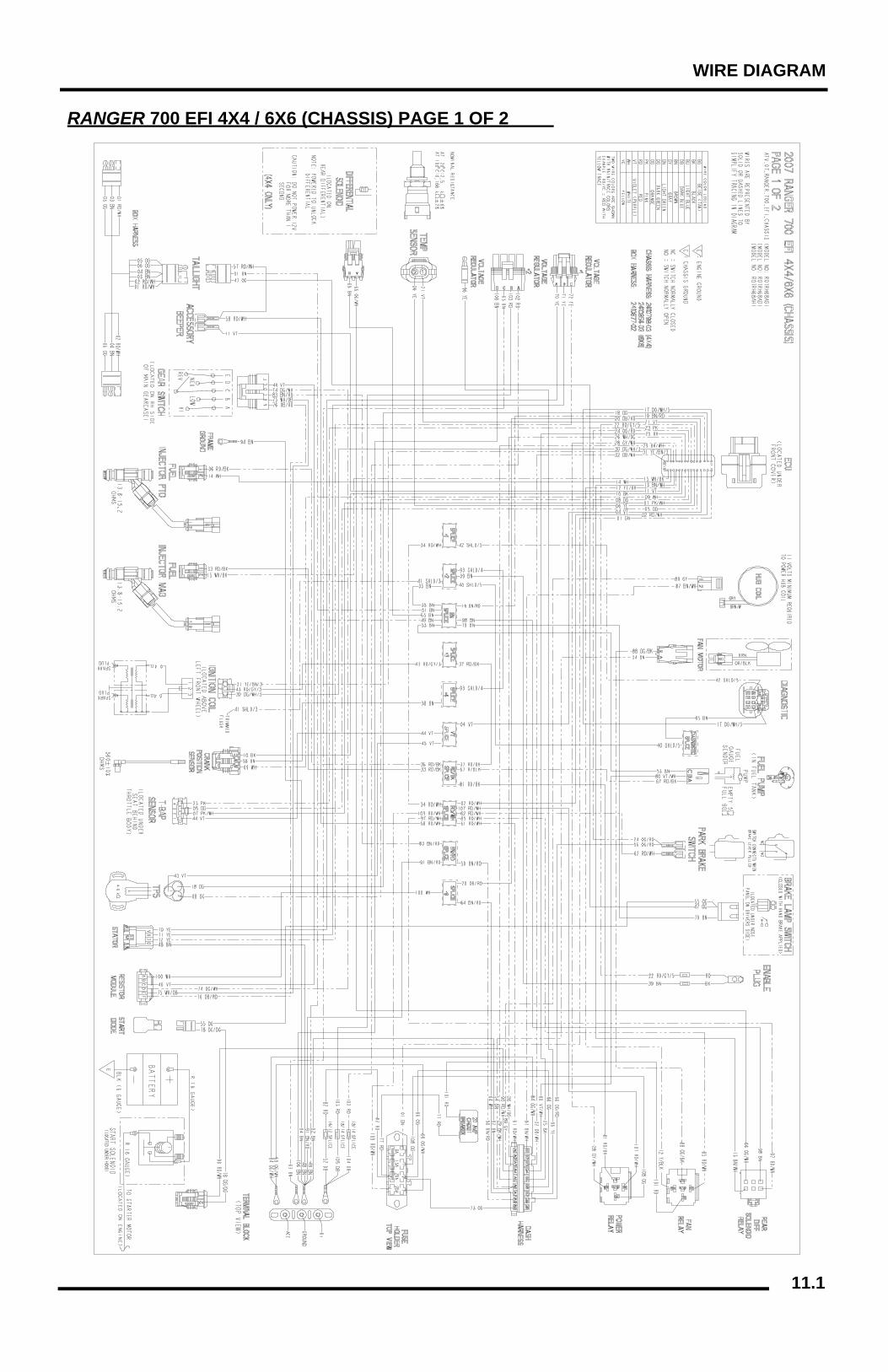
11.1
WIRE DIAGRAM
RANGER 700 EFI 4X4 / 6X6 (CHASSIS) PAGE 1 OF 2

11.2
WIRE DIAGRAM
RANGER 700 EFI 4X4 / 6X6 (CHASSIS) PAGE 2 OF 2
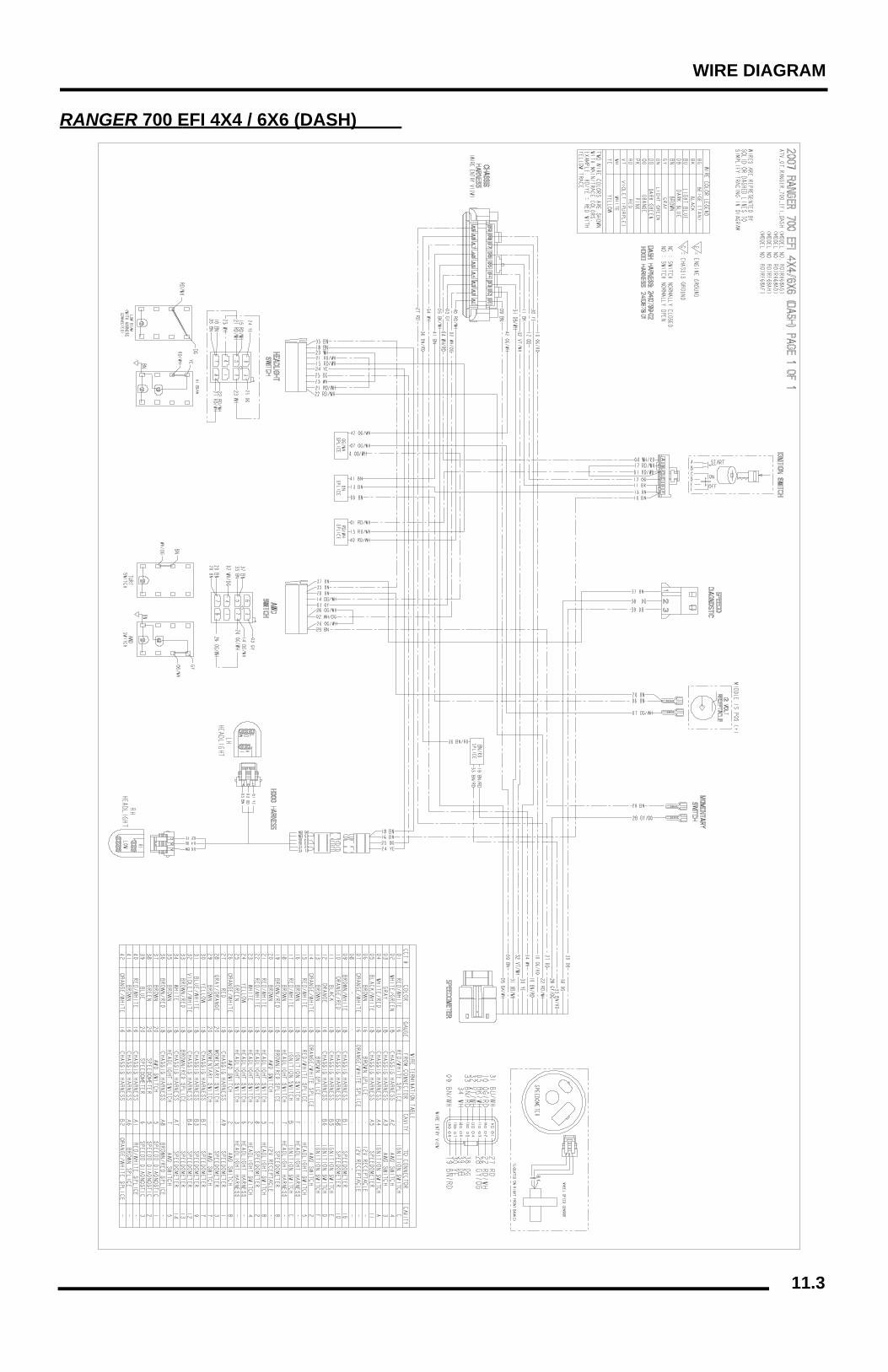
11.3
WIRE DIAGRAM
RANGER 700 EFI 4X4 / 6X6 (DASH)
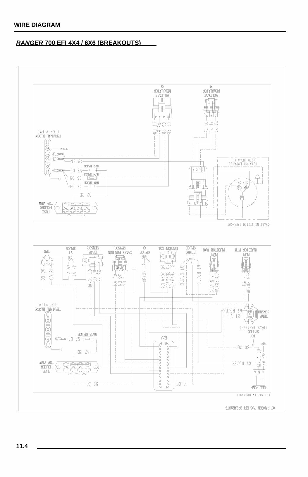
11.4
WIRE DIAGRAM
RANGER 700 EFI 4X4 / 6X6 (BREAKOUTS)