Embed Size (px)
Citation preview

MCFRS Driver Certification Program Page 1 of 16 Pneumatic Tools & Equipment
Pneumatic Tools
Introduction
Pneumatics refers to technology dealing with the application of pressurized gas
(potential energy) to produce mechanical motion (kinetic energy). Pneumatic systems
used in the fire/rescue service primarily use compressed gas as the source of power.
There is a variety of pneumatic tools used in the fire/rescue service, each with a specific
function. While some of these tools were developed specifically for rescue, many are
simply borrowed from other industries, such as the automotive repair industry.
All of the components of a pneumatic tool setup will be discussed in this module,
starting with the air source and working downstream to the actual tool.
Air Sources
The key component to any pneumatic tool or airbag operation is compressed air.
Compressed air can be obtained from a variety of sources on a rescue incident:
Air Compressors
Air compressors provide an unlimited supply
of air. The most common type is the positive-
displacement compressor that uses a
reciprocating piston. (Other types that utilize
impellers or rotary screws do exist.) The
piston air compressor has components similar
to an internal combustion engine: a
crankshaft, connecting rod and piston,
cylinder and a valve head. Typical
compressors come in 1- or 2-cylinder versions
and can be single- or two-stage.
The compressor supplies a storage tank.
When needed, air is drawn from the tank and
the compressor replenishes it. Air
compressors stop supplying the storage tank
when pressure inside the tank reaches a specified limit. When air is consumed and the
pressure in the storage tank drops below a certain level, the compressor starts up
again.

MCFRS Driver Certification Program Page 2 of 16 Pneumatic Tools & Equipment
Air Compressors (continued)
Air compressors can be permanently mounted in a structure or
on apparatus or they can be portable. They can be driven by
an electric motor or an internal combustion engine, either
directly or via a PTO.
The source of the compressor’s power isn’t as important as the
compressor’s capacities for air production. Two important
specs to know about a compressor are its ratings for volume and pressure output.
Volume output for air compressors is expressed in cubic feet per minute (cfm). The cfm
rating of the compressor will dictate the quantity and type of pneumatic tools it can
adequately supply. The pressure rating of the compressor is
also a factor to consider. A higher pressure in the storage
tank means a larger quantity of air. Larger quantities of air
can support tools with higher air consumption rates.
The quality of the air coming out of an air compressor is vital
to tool and equipment performance and service life. Ambient
air contains moisture. When air is compressed, its
temperature increases as well as its ability to hold water
vapor. When air travels away from the compressor to the storage tank, its temperature
decreases. When the temperature decreases, the water vapor condenses and builds
up in the storage tank, air lines, and tools. The water can corrode air tanks and damage
internal components of air tools and equipment. Some air compressors use oil to cool
and lubricate internal components. Some of this oil can leave the compressor with the
air and make its way to tools and equipment. Incorporating air treatment devices like air
dryers and filters are a necessity for prolonging the service life of a pneumatic system.
Cascade Systems
Another air source is a cascade system. A cascade system is a
group of high-pressure cylinders (two or more) connected
together and fed by an air compressor. The cascade systems
on apparatus are usually filled from an external compressor at a
fire station. Air in a cascade system moves from the point of
higher air concentration to the point of lower concentration. The
cylinder with the higher air pressure will force air into the cylinder
with the lower pressure until the pressures in both cylinders
equalize. Since all cylinders in a cascade system are
interconnected, air can be drawn from only one cylinder or a
combination of any or all cylinders. However, pulling from only
one cylinder at a time will help maintain higher pressures in the
MCFRS Driver Certification Program Page 3 of 16 Pneumatic Tools & Equipment
remaining cylinders.
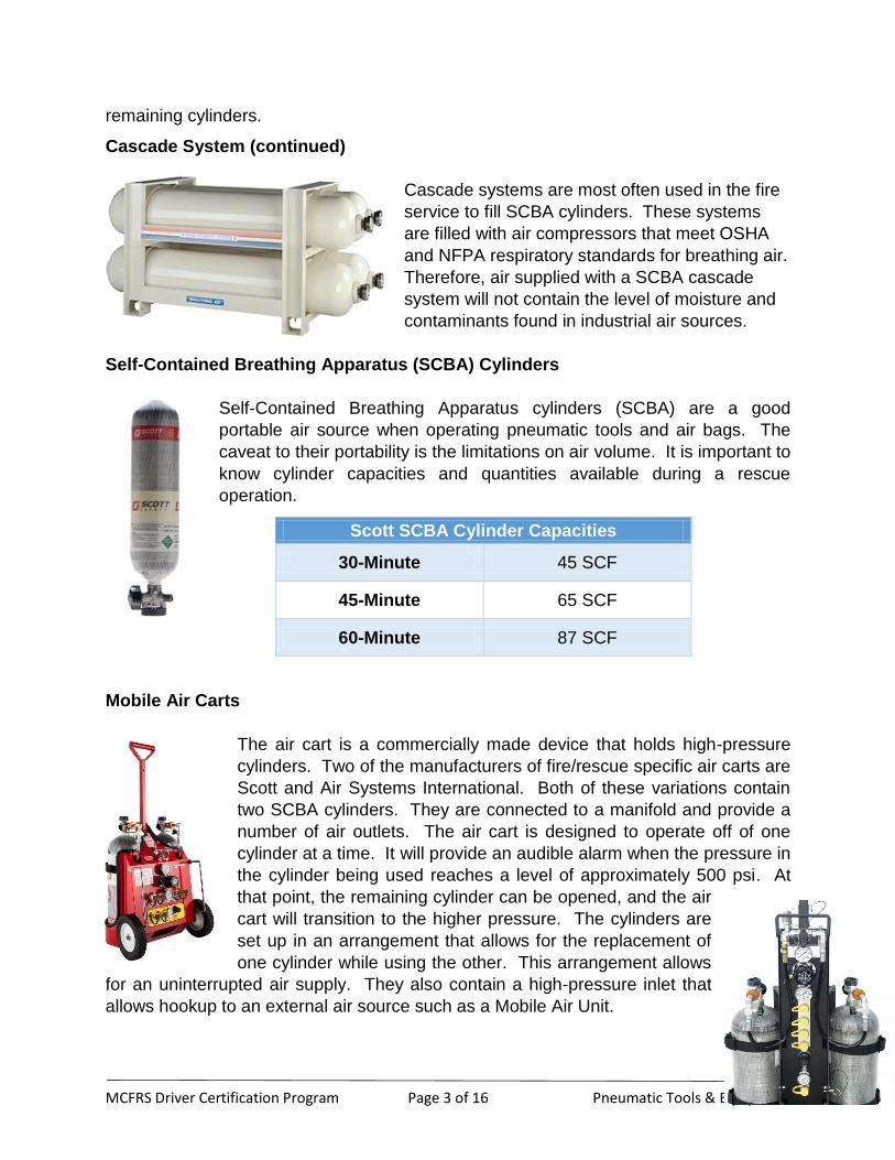
Cascade System (continued)
Cascade systems are most often used in the fire
service to fill SCBA cylinders. These systems
are filled with air compressors that meet OSHA
and NFPA respiratory standards for breathing air.
Therefore, air supplied with a SCBA cascade
system will not contain the level of moisture and
contaminants found in industrial air sources.
Self-Contained Breathing Apparatus (SCBA) Cylinders
Self-Contained Breathing Apparatus cylinders (SCBA) are a good
portable air source when operating pneumatic tools and air bags. The
caveat to their portability is the limitations on air volume. It is important to
know cylinder capacities and quantities available during a rescue
operation.
Mobile Air Carts
The air cart is a commercially made device that holds high-pressure
cylinders. Two of the manufacturers of fire/rescue specific air carts are
Scott and Air Systems International. Both of these variations contain
two SCBA cylinders. They are connected to a manifold and provide a
number of air outlets. The air cart is designed to operate off of one
cylinder at a time. It will provide an audible alarm when the pressure in
the cylinder being used reaches a level of approximately 500 psi. At
that point, the remaining cylinder can be opened, and the air
cart will transition to the higher pressure. The cylinders are
set up in an arrangement that allows for the replacement of
one cylinder while using the other. This arrangement allows
for an uninterrupted air supply. They also contain a high-pressure inlet that
allows hookup to an external air source such as a Mobile Air Unit.
Scott SCBA Cylinder Capacities
30-Minute 45 SCF
45-Minute 65 SCF
60-Minute 87 SCF

MCFRS Driver Certification Program Page 4 of 16 Pneumatic Tools & Equipment

MCFRS Driver Certification Program Page 5 of 16 Pneumatic Tools & Equipment
Air Brake Systems
The air brake system on commercial trucks can be used to supply air for pneumatic
tools. The engine air compressor produces air for the air brakes and other components.
These air systems generally operate around 120 psi.
Tractor trailers have an air connection between the tractor and the trailer in order to
provide an air supply for the rear brakes. There will be two hoses, one red and the
other blue. The hoses are connected via a
glad hands coupling. The blue hose is used
for normal braking operation and it is referred
to as service airline. The red hose is the
emergency airline. In the event that the red
airline becomes disconnected (such as when
the trailer disconnects from the tractor), the
trailer brakes are automatically applied. On
some trailers, the same type of connection
can be found at the rear end of the trailer.
The service and emergency airlines are supplied by the engine air compressor on the
tractor. An adapter can be used to make the connection to the glad hands coupling on
the rear of the tractor, providing an air supply for pneumatic tools and equipment.
Fire Apparatus Auxiliary Air
Fire apparatus will typically have air connection(s) for auxiliary air hookup. These
connections are supplied by the air reservoirs that are part of the vehicles air system.
Just like the commercial air brake systems previously discussed, fire apparatus air
systems can provide approximately 120 psi of useable air.
Tire Fill Adapter
With the correct type of adapters, we can get air from the tires of
vehicles on the scene. Generally, fire apparatus tires have an
inflation pressure ranging from 110 to 120 psi while passenger cars
may only have 25 to 35 psi to offer. Consideration should be given to
the volume of air necessary to accomplish a task when utilizing this
air source.

MCFRS Driver Certification Program Page 6 of 16 Pneumatic Tools & Equipment
Air Regulators
Air sources such as SCBA cylinders, air carts, cascade systems and some air
compressors produce high pressure air (pressures in SCBA cylinders can be as high as
5500 psi). However, the majority of the pneumatic tools and airbags (even “high
pressure” airbags) used in the fire/rescue service operate below 150 psi. Exceeding the
normal operating pressures of pneumatic equipment can not only be a waste of
valuable air supply, but also potentially damaging to the equipment. Therefore, a
pressure-reducing device (pressure regulator) is needed to provide useable low
pressure air.
Components and Operation
Pressure regulators are comprised of three functional elements:
A pressure reducing or restrictive element (generally a poppet valve)
A sensing element (generally a diaphragm or piston)
A reference force element (generally a spring)
At a basic level, an air regulators work like this:
1. High pressure air flows into the high pressure chamber of the regulator
2. The adjustment screw is tightened, which compresses the spring
3. The spring compression produces force that pushes down on the
diaphragm/piston
4. The force on diaphragm/piston pushes down on the valve stem, opening the
poppet valve
5. Air is able to enter the low pressure chamber of the regulator
6. The regulated air creates a force that opposes the diaphragm/piston and closes
the poppet valve.
7. Increasing the force in the spring will result in an increase in opposing force from
the air in the low pressure chamber and thus an increase in outlet air pressure.
Decreasing the force in the spring will have the opposite effect

MCFRS Driver Certification Program Page 7 of 16 Pneumatic Tools & Equipment
Diaphragm regulators are generally more sensitive to pressure changes and react more
quickly. They are used for increased accuracy and low pressure applications. Piston
regulators are more rugged and used when higher outlet pressures are required and are
not held to as tight a tolerance. Both types are typically equipped with gauges to read
both inlet and outlet pressures.
A third type of regulator that is sometimes used in the fire/rescue service is the
permanently-set or preset regulator. This regulator has a sensing element that is
already set and is not adjusted during use. The outlet pressure on this style of regulator
is set at the factory, generally at maximum of 175 psi. Hurst and Paratech utilize this
style of regulator with some of their airbag controller setups.
Maintenance and Use
General operating practices are outlined in this section. Manufacturer’s recommended
operating procedures should always be followed when using a regulator.
Prior to connecting a regulator to an air source, perform the following:
Check the regulator for any damage
Ensure that inlet and outlet pressure gauges are reading “zero”; the regulator will
still function with incorrect gauge readings, but a faulty outlet pressure gauge
prevents accurate outlet pressure settings which could damage the equipment
connected to the regulator
Check the high pressure connection for the presence of an O-ring; replace if
necessary
If adjustable, ensure that the adjustment knob/handle is turned fully
counterclockwise to lower outlet pressure and close the poppet valve, preventing
the flow of air through the regulator. If the poppet valve is not closed when the
high pressure source is opened, air can flow through the regulator, possibly at
pressures too high for downstream equipment
Diaphragm Regulator Piston Regulator Hurst PermaSet Regulator

MCFRS Driver Certification Program Page 8 of 16 Pneumatic Tools & Equipment
Maintenance and Use (continued)
Once the regulator is connected to the air source, the operator should:
Check for air leaks at the inlet (high pressure) coupling; if leaks exist, shut down
the air source, check for O-ring issues and attempt to reconnect
Connect the outlet (low pressure) coupling to an appropriate air hose
If equipped, open the delivery shutoff valve on the regulator – this will allow air to
flow through the regulator outlet downstream to the equipment
Slowly turn the adjustment knob/handle clockwise to increase the outlet pressure
to the correct setting; it may be necessary to fine tune the pressure adjustment
once air tool operation begins and air is flowing through the regulator
(Permanently set or preset regulators will automatically provide the set working
pressure.)
Upon completion of the air tool/equipment operation, shut down the regulator as follows:
Turn off the air supply
If adjustable, reduce the regulator outlet pressure to “zero” by turning the
adjustment knob/handle fully counterclockwise
Disconnect the air hose from the outlet coupling
Turn the adjustment knob/handle clockwise to bleed the pressure from the inlet
side of the regulator
Once both pressure gauges are at “zero”, return the adjustment knob/handle
back to the fully counterclockwise position and disconnect the air source
Regulators should be stored in a clean, dry environment. Gauges are susceptible to
damage so appropriate precautions should be taken to protect them. Any damage to
the regulator or gauges and/or faulty operation should place the regulator out of service
for repairs or replacement.

MCFRS Driver Certification Program Page 9 of 16 Pneumatic Tools & Equipment
Air Hoses
Air hoses are a critical component of any pneumatic tool and airbag setup. They are
the connecting medium between the equipment and can have a direct effect on air
volume and pressure. Air hoses can be constructed of various types of rubber or plastic
and may contain a form of fabric reinforcement. The hose should be marked with a
service or working pressure; never exceed the manufacturer’s recommended operating
pressures.
Hose lengths can be short (around 16 feet for many airbag systems) or as long as 200
feet (common length for apparatus hose reels). Much like fire hose, air hose creates
friction losses. The magnitude of these losses depend on hose diameter and length as
well as air flow.
The Association for Rubber Products Manufacturers (ARPM) provides some tabulated
data in their “Hose Handbook” referencing friction loss in air hose. Some of this data is
shown in the tables below:
Friction Loss in Air Hose (psi) per 100-foot length
Hose I.D. (inch) Gauge Pressure at
Line (psi)
Cubic Feet Free Air Per Minute (SCFM)
3.0 5.0 10.0
1/4
100 3.73 10.36 -
150 2.60 7.21 -
200 1.99 5.53 22.14
3/8
100 0.44 1.23 4.92
150 0.31 0.86 3.42
200 0.24 0.66 2.63
From ARPM Hose Handbook, 8th
Edition – Table 11-4A
Friction Loss for Pulsating Air through Hose (psi) per 100-foot length
Hose I.D. (inch) Gauge Pressure at
Line (psi)
Flow of Free Air (SCFM)
30 40 50
1/2
50 10.0 20.2 36.2
80 5.6 12.0 21.6
100 4.6 9.6 16.8
From ARPM Hose Handbook, 8th
Edition – Table 11-4B
**The above tables refer to “Free Air” at atmospheric pressure (14.7 psi) and 80°F
**The pressure drops listed assume hose with smooth I.D. tubing and full-flow couplings. Greater
pressure drops will occur in hose with rough I.D. tubing or restrictions at couplings/fittings.

MCFRS Driver Certification Program Page 10 of 16 Pneumatic Tools & Equipment
The majority of pneumatic tools and equipment used in the fire service will require a
minimum air hose diameter of 3/8”. Smaller ¼” air hoses (commonly found on small
home air compressors) will not meet volume requirements and can result in inefficient
tool operation or even damage.
3/8” Air Hose
1/4” Recoil Air Hose

MCFRS Driver Certification Program Page 11 of 16 Pneumatic Tools & Equipment
Pneumatic Tools
As mentioned at the beginning of the module, the majority of pneumatic tools used in
rescue are actually designed for the automotive repair industry. However, there are
some tools designed specifically for fire/rescue applications.
Types of Pneumatic Tools
Impact Wrench
Pneumatic impact wrenches provide high torque output. In
addition to rotation, impact wrenches apply a hammering force.
They are commonly used in automotive, construction, and
assembly industries.
Impact wrenches come in drive sizes similar to ratchet sets.
Common automotive drive sizes are ¼”, 3/8”, ½”, ¾” and 1”. For
industrial applications, drive sizes can be as large as 11/2” and
21/2”. Due to the high torque of an impact wrench, regular sockets should NOT be used.
Standard chrome sockets are fairly brittle and can shatter from too much vibration.
Impact sockets are made from chromolybdenum, which is a softer more malleable
material. These sockets are designed to absorb the high impact forces from an
impact wrench instead of shattering like standard sockets.
Torque ratings can range considerably depending on the size of the impact
wrench and its application. Working torque ranges can be anywhere from 25 to
350 lb-ft. Maximum torques can exceed 1000 lb-ft.
Air consumption also varies with size and application. For automotive applications,
average consumption rates can be 5-10 cfm. Under load, these torque wrenches may
use in excess of 20 cfm. For industrial and manufacturing applications, air consumption
rates can dramatically increase – some as high as 40 cfm.
Air Ratchet
Air ratchets apply far less torque and operate
at lower RPMs than impact wrenches. They
are designed to increase efficiency and save
time in applications where standard ratchets
would be used.
Air Ratchet (continued)

MCFRS Driver Certification Program Page 12 of 16 Pneumatic Tools & Equipment
Standard drive sizes for air ratchets are ¼”, 3/8” and ½”. Due to the lower torque ratings,
impact sockets are not required. Torque ratings can range from 5 to 75 lb-ft.
Average air consumption rates for air ratchets are around 4-5 cfm.
Air Hammers
The air hammer (or “air chisel” as it’s sometimes called) is one of the more commonly
used pneumatic tools in rescue. In fact, a larger version of an air hammer, which will be
discussed later in this module, was developed specifically for fire/rescue applications.
As the name suggests, air hammers create a hammering action through the use of a
piston.
The working end of the air hammer is the chisel. Chisels are used to pierce and cut
metal. There are numerous types of chisel designs, each with different specialties.
Chisels are
held in the
air hammer
with a
retainer.
There are
two types of
retainers:
coil spring
and quick change. Most air hammers can be fitted with either type,
but the quick change retainer is preferred for fire/rescue work. Quick
change retainers are faster and easier to use and also minimize the
risk of a chisel dislodging from the hammer during use associated
with coil spring retainers.
Air consumption rates for air
hammers are around 2-3 cfm, with
some peaking between 10-15 cfm under load.
Some Common Types of Chisels
(from left to right)
Tailpipe/muffler cutter
Straight/flat chisel
Cutting chisel
Edging tool
Tapered punch
Coil Spring
Retainer
Quick Change
Retainer
MCFRS Driver Certification Program Page 13 of 16 Pneumatic Tools & Equipment
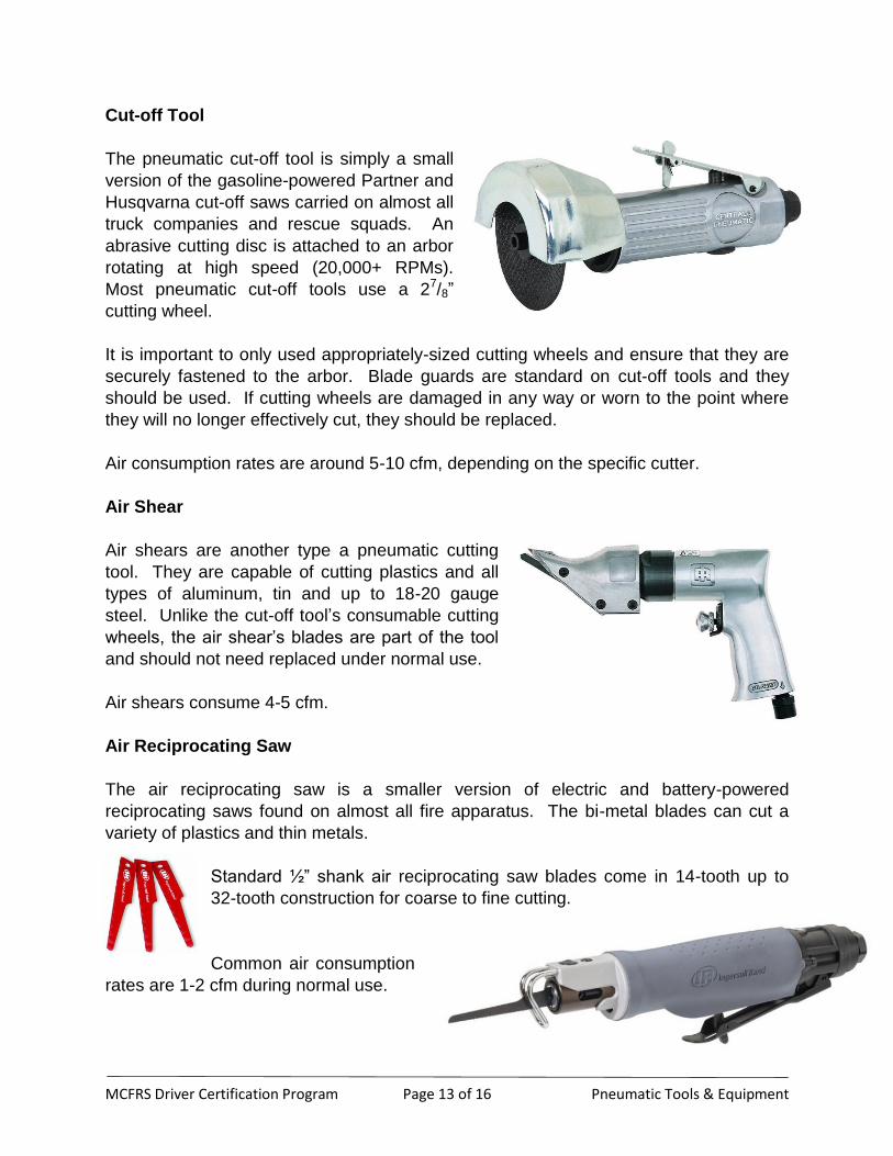
Cut-off Tool
The pneumatic cut-off tool is simply a small
version of the gasoline-powered Partner and
Husqvarna cut-off saws carried on almost all
truck companies and rescue squads. An
abrasive cutting disc is attached to an arbor
rotating at high speed (20,000+ RPMs).
Most pneumatic cut-off tools use a 27/8”
cutting wheel.
It is important to only used appropriately-sized cutting wheels and ensure that they are
securely fastened to the arbor. Blade guards are standard on cut-off tools and they
should be used. If cutting wheels are damaged in any way or worn to the point where
they will no longer effectively cut, they should be replaced.
Air consumption rates are around 5-10 cfm, depending on the specific cutter.
Air Shear
Air shears are another type a pneumatic cutting
tool. They are capable of cutting plastics and all
types of aluminum, tin and up to 18-20 gauge
steel. Unlike the cut-off tool’s consumable cutting
wheels, the air shear’s blades are part of the tool
and should not need replaced under normal use.
Air shears consume 4-5 cfm.
Air Reciprocating Saw
The air reciprocating saw is a smaller version of electric and battery-powered
reciprocating saws found on almost all fire apparatus. The bi-metal blades can cut a
variety of plastics and thin metals.
Standard ½” shank air reciprocating saw blades come in 14-tooth up to
32-tooth construction for coarse to fine cutting.
Common air consumption
rates are 1-2 cfm during normal use.
MCFRS Driver Certification Program Page 14 of 16 Pneumatic Tools & Equipment
Maintenance and Use
Air pressure is an important component of proper tool operation. The pneumatic tools
mentioned in this module typically have manufacturer-recommended operating
pressures of 90 psi. The tools will operate at pressures above 90 psi, which will
increase torque and possibly improve performance. However, in the long run, this will
reduce the life expectancy of the tool. Operating pressures less than 90 psi will result in
tool inefficiency and decreased performance. One common mistake made by operators
is to set the air regulator at the tool operating pressure and never give it a second
thought. However, by the time the air reaches the actual tool, the pressure may be
significantly reduced. Several factors (such as air leaks, hose configurations and
lengths, the number and types of couplings, etc.) can reduce air pressure. So if the tool
is not functioning as it should, this could be one possible cause.
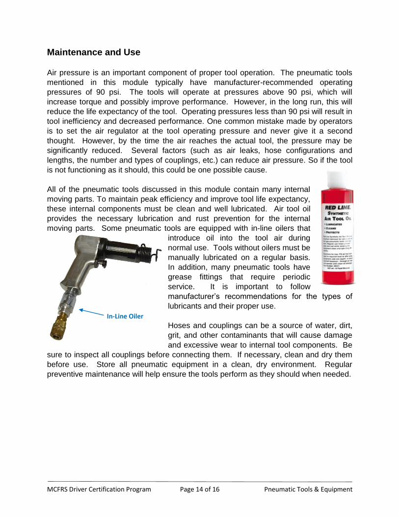
All of the pneumatic tools discussed in this module contain many internal
moving parts. To maintain peak efficiency and improve tool life expectancy,
these internal components must be clean and well lubricated. Air tool oil
provides the necessary lubrication and rust prevention for the internal
moving parts. Some pneumatic tools are equipped with in-line oilers that
introduce oil into the tool air during
normal use. Tools without oilers must be
manually lubricated on a regular basis.
In addition, many pneumatic tools have
grease fittings that require periodic
service. It is important to follow
manufacturer’s recommendations for the types of
lubricants and their proper use.
Hoses and couplings can be a source of water, dirt,
grit, and other contaminants that will cause damage
and excessive wear to internal tool components. Be
sure to inspect all couplings before connecting them. If necessary, clean and dry them
before use. Store all pneumatic equipment in a clean, dry environment. Regular
preventive maintenance will help ensure the tools perform as they should when needed.
In-Line Oiler
MCFRS Driver Certification Program Page 15 of 16 Pneumatic Tools & Equipment
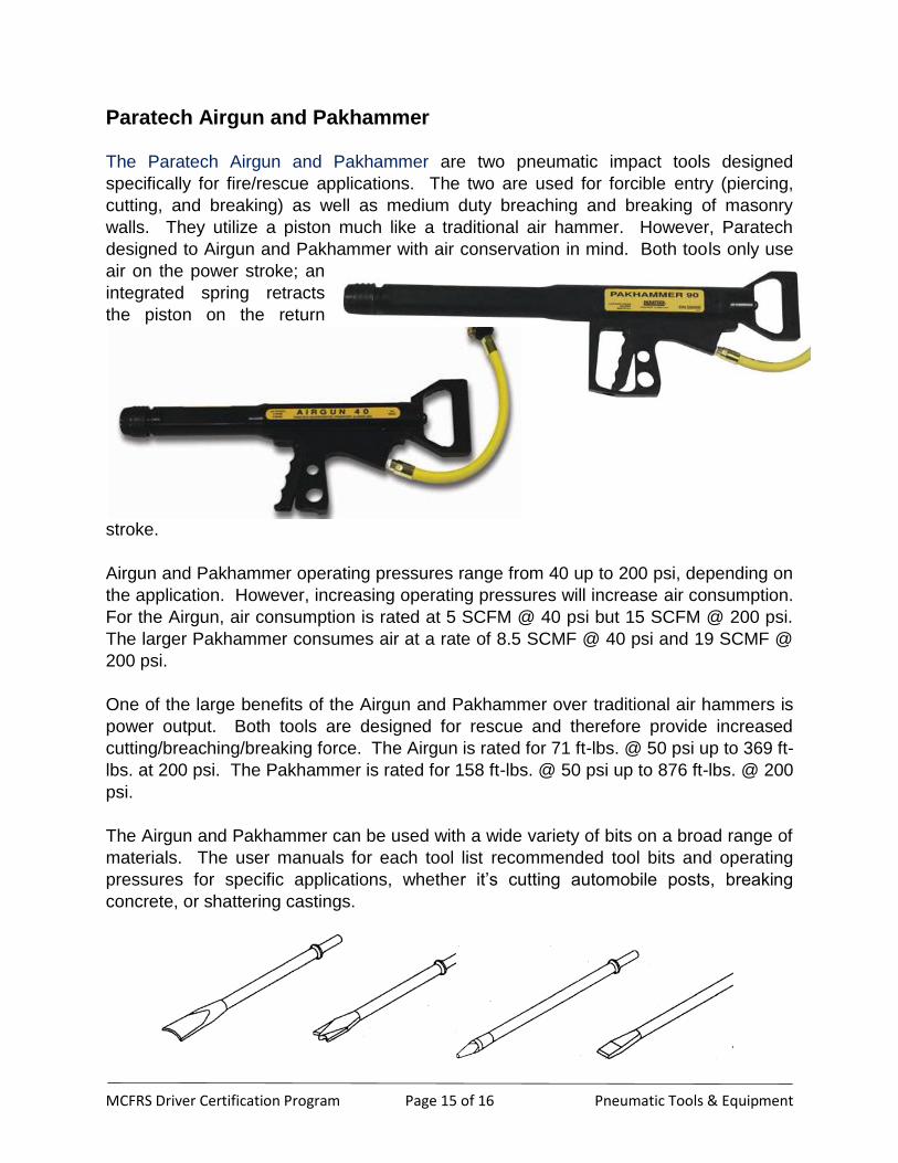
Paratech Airgun and Pakhammer
The Paratech Airgun and Pakhammer are two pneumatic impact tools designed
specifically for fire/rescue applications. The two are used for forcible entry (piercing,
cutting, and breaking) as well as medium duty breaching and breaking of masonry
walls. They utilize a piston much like a traditional air hammer. However, Paratech
designed to Airgun and Pakhammer with air conservation in mind. Both tools only use
air on the power stroke; an
integrated spring retracts
the piston on the return
stroke.
Airgun and Pakhammer operating pressures range from 40 up to 200 psi, depending on
the application. However, increasing operating pressures will increase air consumption.
For the Airgun, air consumption is rated at 5 SCFM @ 40 psi but 15 SCFM @ 200 psi.
The larger Pakhammer consumes air at a rate of 8.5 SCMF @ 40 psi and 19 SCMF @
200 psi.
One of the large benefits of the Airgun and Pakhammer over traditional air hammers is
power output. Both tools are designed for rescue and therefore provide increased
cutting/breaching/breaking force. The Airgun is rated for 71 ft-lbs. @ 50 psi up to 369 ft-
lbs. at 200 psi. The Pakhammer is rated for 158 ft-lbs. @ 50 psi up to 876 ft-lbs. @ 200
psi.
The Airgun and Pakhammer can be used with a wide variety of bits on a broad range of
materials. The user manuals for each tool list recommended tool bits and operating
pressures for specific applications, whether it’s cutting automobile posts, breaking
concrete, or shattering castings.

MCFRS Driver Certification Program Page 16 of 16 Pneumatic Tools & Equipment
Routine maintenance of the Airgun and Pakhammer will keep them operating at peak
efficiency. The surface of the tools should be kept clean of dirt, grease, etc. If the tool
has been operated in a dusty, abrasive environment or if the tool bit retainer assembly
is subjected to a damp or wet material, Paratech
recommends cleaning the retainer assembly with dry
cleaning solvent and lubricating with air tool oil
afterwards.
Both tools are fitted with an in-line oiler. As
air passes through the oiler, a controlled
volume of lubrication is picked up with the
air to maintain continuous fog lubrication of
the internal components. The oil level
should be periodically checked. If empty, fill the oiler housing until half-full
with Marvel® Air Tool Oil.