Embed Size (px)
Citation preview

PNEUMATIC HIGH SPEED SPINDLE WITH AIR
BEARINGS
Terenziano RAPARELLI, Federico COLOMBO and Rodrigo VILLAVICENCIODepartment of Mechanics, Politecnico di TorinoCorso Duca degli Abruzzi 24, Torino, 10129 Italy
(E-mail: [email protected])
ABSTRACT
This article describes different experimental tests performed on a pneumatic spindle with gas bearings in orderto evaluate its maximum rotational speed and stability. In particular the rotor unbalance response, the powerlosses calculated from deceleration tests, the thermal transient due to viscous losses are calculated and analyzed.
KEY WORDS
Pneumatic Spindle, Air Bearings, Feed hole, Thermal transient
INTRODUCTION
These applications are related both to high precisiondevices, e.g. for measuring machines, both to highspeed rotating machines, e.g. high speed spindles foroperations of finishing or drilling. During the last fiftyyears the use of no contact air bearings in rotating ma-chines has been the object of interest by part of theresearches in order to obtain bearings that support ro-tational speeds out of the range of conventional ballbearings [1].
Limitations on the maximum rotational speed arerepresented by centrifugal forces and by the well-knowwhirl instability of gas bearings. Nevertheless gas bear-ings enable to reach higher rotational speeds than rollingbearings, compared at the same diameter. Focusing
the attention on the high rotational speeds, a broadspectrum of applications demand the use of gas bear-ings, in manufacturing industry (high speed machin-ing, printed circuit boards drilling, micro-milling andwafer dicing) and not only (high speed compressorsand turbines). In the first case the high speed is aimedto obtain high quality surface finishing or the correcttangential cutting speed with micro-tools; in the sec-ond case it is due to a reduction of the dimensions ofthe turbomachines.The drawbacks of pneumatic bearings can be summa-rized in the following phenomena: the air-hammer [4],the unstable whirl [5][6], the relative low damping. Allthese problems must be solved to design such systemsand obtain a stable operation of the rotor to containits dynamic runout.
527

Figure 1: Sketch of the pneumatic spindle.
In this paper, a completely pneumatic spindle (Fig-ure 1) designed and realized at the Mechanical Depart-ment of Politecnico di Torino [2] was tested experimen-tally. The stability of the spindle was verified monitor-ing the dynamic runout by means of displacement sen-sors facing the rotor and positioned along perpendicu-lar radial directions. The bearings air consumption [3]and the external surface temperature were registeredat different rotating speeds. The air turbine used toaccelerate the rotor was also characterized.Particular attention was given to the thermal analysisto evaluate the effects of temperature on the air clear-ance and prevent any rotor grip.
Figure 2: Prototype pneumatic spindle.
PROTOTYPE AND TEST BENCH
Figure 2 depicts the cross section of rotor (2), which issustained by two radial bearings (4) of axial length 100mm and a double thrust bearing (3) composed by threerings. The bearings are supplied by means of channelsdrilled in the housing (1) and in the three rings of thethrust bearing. The thrust bearing has inner and outerradius 49 mm and 79 mm respectively. The thicknessof the central ring defines the axial air gap. The nom-inal radial and axial clearance are 27 µm and 19 µmrespectively. The rotor is accelerated by a pneumaticturbine (5) machined on the rotor itself.
Figure 3: Transducers and Data Acquisition system.
The test bench designed to measure the performanceof the pneumatic spindle was endowed of a data acqui-sition system and of pneumatic supply lines. Displace-ment capacitive transducers, see Figure 3 are arrangedradially and axially facing the rotor. Four radial trans-ducers are placed in two planes (close to each bearing)along X and Y directions. In Figure 3 are representedthe measuring planes on which sensors (1) and (2) areset on the turbine side and sensors (3) and (4) on thethrust side. Sensor (5) is set along the axial directionon the thrust side. The sensors are connected to theamplifiers (6) and to the signal conditioner (7), whoseanalog output is detected by means of the data ac-quisition system. An optical tachometer (8) is placedin front of the spindle along the axial direction. Thepulse train signal of the sensor is sent to counters thatcalculate the spindle rotational frequency. A series of
528
thermocouples type T (9) are disposed on the cartersurface to measure its external temperature distribu-tion; their signal is amplified by means of amplifier(10). The temperature of the discharged air is alsomeasured next to the axial and radial bearings.The pneumatic system (Figure 10) consists of two sup-ply lines: one for the turbine and the other for thebearings. This last is endowed of a 100 l tank withnon-return valves, which is inserted downstream thepressure regulator. It can be useful in case the supplyline fails to prevent a spindle damage.The output signal of the displacement transducers isacquired with a 50 kHz sampling rate. The signals oftwo perpendicular sensors are composed in an XY plotto visualize the spindle orbits on the measuring planes.In this way the conical and cylindrical modes are vi-sualized. By means of a FFT algorithm the Fourierspectrum of the signal is obtained in order to studythe unbalance spindle response and verify the absenceof sub-synchronous whirl. Six thermocouples were setin correspondence of the following points (see the Fig-ure 4):1-turbine housing,2-air discharge next to the turbine,3-measuring plane on turbine side,4-measuring plane on thrust side5-rotor flange,6-air discharge next to the thrust bearing.
Figure 4: Thermocouple measuring points.
EXPERIMENTAL ACTIVITY
The experimental activity involved beforehand the mea-sure of the air gaps, then were carried out:
1) the unbalance spindle response,2) the bearings air consumption,3) deceleration tests,4) temperature tests,5) the turbine characterization.
The measuring of the rotor and bearings dimensionswas intended to evaluate the radial and axial air clear-ance, to which the bearing stiffness, the viscous lossesand the spindle stability during operation are very sen-sitive. The mean values obtained after many dimen-sional tests are reported in Table 1:
Table 1: Dimension of bearings and air gaps.
Rotor dia. on turbine side 49.454 mmRotor dia. on thrust side 49.452 mm
Bushing dia. on turbine side 49.508 mmBushing dia. on thrust side 49.507 mmRadial gap on turbine side 27 µmRadial gap on thrust side 27 µm
Thickness of spindle flange 11.181 mmThickness of central ring 11.218 mm
Axial gap 19 µm
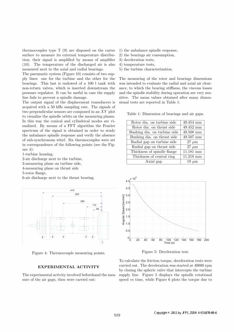
Figure 5: Deceleration test.
To calculate the friction torque, deceleration tests werecarried out. The deceleration was started at 40000 rpmby closing the spheric valve that intercepts the turbinesupply line. Figure 5 displays the spindle rotationalspeed vs time, while Figure 6 plots the torque due to
529

viscous losses on bearings, that was obtained as a func-tion of the rotational speed considering the mass mo-ment of inertia of the spindle.
Figure 6: Friction viscous torque.
The temperature trends vs time are reported in Fig-ure 7. They refer to a gauge supply pressure of 5 barto the bearings and an initial rotational speed of 40000rpm. After 110 minutes the spindle was shut down. Itwas observed that the temperature increases movingfrom the turbine to the thrust bearing, where the tan-gential speeds are higher. After the spindle shut downthe temperature becomes uniform and begins to de-crease, with the exception of the turbine housing, thatpresents an initial increase of temperature.
Figure 7: Curves of temperature vs. time.
The spindle orbits were measured every 1000 rpm start-ing from 0 to 42000 rpm. The spindle during opera-tion suffers from centrifugal expansion; for this reasonits surface approaches to the sensors, that are fixed tothe housing. This displacement is visible in the spindleorbits show in, Figure 8 and Figure 9.
Figure 8: Spindle orbits measured on the turbine sideplane at different rotational speeds; (a)non filtered, (b)filtered.
The driving turbine was characterized as a function ofthe rotational speed. Its air consumption was mea-sured with a rotameter and the pressure was detectedat the input and output of the turbine, Figure 10. InTable 2 it is shown the correspondence between theair consumption and the supply pressure of the tur-bine and the steady rotational speed without externalpayload. In these conditions it is calculated the powerabsorbed by the turbine, that is equal to the powerdissipated.
530

Figure 9: Spindle orbits measured on the thrust sideplane at different rotational speeds; (a)non filtered, (b)filtered.
Table 2: Power Consumption
rpm turbine air gauge press powerflow(l/min)ANR (bar) (kW)
10000 394.66 0.25 0.1615000 416.65 0.425 0.3020000 460.54 0.525 0.4025000 435.60 0.8 0.5830000 414.32 1.09 0.7535000 417.10 1.325 0.9240000 382.82 1.75 1.12
RESULTS
The orbits of the spindle during rotation are plotted
Figure 10: Pneumatic system used to characterize thedriving turbine.
in Figure 8 for the measuring plane on the turbineside and in Figure 9 for the measuring plane on thethrust side. The figures compare the original signalwith the signal obtained with a low pass filter. Thedynamic runout is confined under 7 µm. In Figure 11the amplitudes of the runout measured by the four ra-dial sensors are plotted against the rotational speed.The first critical speed is about 35000 rpm. The effectof centrifugal forces is visible in Figure 12, where themean displacement values detected from radial sensorsis plotted against the rotor speed.In Figure 12 it is represented the displacement the rotorcenter around the mean value.
Figure 11: Amplitude displacement.
531

Figure 12: Displacement of Y axis around the centerof the orbit (turbine side).
The unbalance response evidences both cylindrical andconical modes. In Figure 13 and Figure 14 are repre-sented examples of conical modes at 30000 rpm and40000 rpm respectively.
Figure 13: Mode of rotation at 30000 (rpm).
The waterfall diagram of Figure 15 shows that theunbalance response is only synchronous and the sub-synchronous whirl is absent in the tested range of speed.
Figure 14: Mode of rotation at 40000 (rpm).
Figure 15: Waterfall Diagram.
The temperature of the rotor increase during operationdue to viscous losses in the air gap. It remains in asafety range in which the spindle can operate for a longtime without problems.
CONCLUSIONS
An experimental activity was developed to evaluatethe performance of a turbo pneumatic spindle with gasbearings. In synthesis the following conclusions can belisted:
532

• the spindle rotates in stable conditions up to 40000rpm;
• the spindle temperature in steady conditions at40000 rpm remains under 75oC and the thermaleffects due to viscous actions do not compromisethe operation of the spindle;
• the friction torque of gas bearings is very low(around 0.13 Nm at the maximum speed) due tothe low air viscosity.
REFERENCES
[1] Krzysztof, Czolczynski, ”Rotordynamics of gas-lubricated journal bearing systems, New York.(1999), Springer.
[2] Belforte G., Raparelli T., Viktorov V., TrivellaA., Colombo F., An experimental study of high-speed rotor supported by air bearings: test rigand first experimental results, Tribology Inter-national, 2006, 39-8, pp.839-845.
[3] Belforte G., Raparelli T., Viktorov V., TrivellaA., Discharge coefficients of orifice type restrictorfor aerostatic bearings, Tribology International,2007, 40, pp.512-521.
[4] Tauler H.M.,Stowell T.B., Pneumatic hammer inan externally pressurized orifice-compensated airjournal bearing, Tribology International, 2003,36, pp.585-591.
[5] Waumans T., Peirs J., Reynaerts D., Al-BenderF., On the dynamic stability of high-speed gasbearings: Stability study and experimental vali-dation, 2011, Laboratory Soete
[6] Brzeski L.,Kazimierski Z., Experimental investi-gation of precision spindles equipped with highstiffness gas journal bearings, Precision Engineer-ing, 2003, 23, pp.155-163.
533