Embed Size (px)
Citation preview

A L T R A I N D U S T R I A L M O T I O N
Pneumatic Clutches and Brakes

Altra is a leading global designer and producer of a wide range of electromechanical power transmission and motion control components and systems. Providing the essential control of equipment speed, torque, positioning, and other functions, Altra products can be used in nearly any machine, process or application involving motion. From engine braking systems for heavy duty trucks to precision motors embedded in medical robots to brakes used on offshore wind turbines, Altra has been serving customers around the world for decades.
Altra’s leading brands include Ameridrives, Bauer Gear Motor, Bibby Turboflex, Boston Gear, Delevan, Delroyd Worm Gear, Formsprag Clutch, Guardian Couplings, Huco, Jacobs Vehicle Systems, Kilian, Kollmorgen, Lamiflex Couplings, Marland Clutch, Matrix, Nuttall Gear, Portescap, Stieber, Stromag, Svendborg Brakes, TB Wood’s, Thomson, Twiflex, Warner Electric and Wichita Clutch.
VISIT US ON THE WEB AT ALTRAMOTION.COM
Altra Motion
Wichita ClutchWichita Clutch, founded in 1949, is a leading global designer and manufacturer of heavy-duty clutches and brakes that are essential components in industrial process equipment. Backed by extensive application experience, Wichita engineers utilize the latest design technologies and materials to provide innovative clutch and brake solutions that precisely meet their customer’s most demanding requirements.
A full range of Wichita solutions, including hydraulic clutches and brakes, air clutches, air brakes, water-cooled clutches and brakes, and fluid couplings, are used extensively around the world by major OEMs in metalworking, steel, marine, pulp & paper, material handling, mining, and energy.
VISIT US ON THE WEB ATWWW.WICHITACLUTCH.COM
Altra is a leading global designer and producer of a wide range of electromechanical power transmission and motion control components and systems. Providing the essential control of equipment speed, torque, positioning, and other functions, Altra products can be used in nearly any machine, process or application involving motion. From engine braking systems for heavy duty trucks to precision motors embedded in medical robots to brakes used on offshore wind turbines, Altra has been serving customers around the world for decades.
Altra’s leading brands include Ameridrives, Bauer Gear Motor, Bibby Turboflex, Boston Gear, Delevan, Delroyd Worm Gear, Formsprag Clutch, Guardian Couplings, Huco, Jacobs Vehicle Systems, Kilian, Kollmorgen, Lamiflex Couplings, Marland Clutch, Matrix, Nuttall Gear, Portescap, Stieber, Stromag, Svendborg Brakes, TB Wood’s, Thomson, Twiflex, Warner Electric and Wichita Clutch.
VISIT US ON THE WEB AT ALTRAMOTION.COM
Altra Motion

A
B
C
D
E
F
1P-1100-WC-GB-A4 7/21 www.wichitaclutch.com
Dependable Torque Control ProductsWichita clutch es and brakes provide the high speed ac cel er a tion and de cel er a tion that are essential in modern process equip ment. They are avail able in a variety of designs and mounting con fig u ra tions and are used ex tensive ly around the world by leading OEM’s in met al work ing, steel, pulp/paper, material handling, paper converting, marine, mining and energy.
Wichita provides custom designs to meet your par tic u lar ap pli ca tion re quire ments, giving you the right solution to meet all your power trans mis sion needs.
Do not repair clutches and brakes (with or without a guard) while they are ro tat ing or with a load en gaged.
Do not disassemble while air-tube is pressurized.
Heavy components should be handled carefully. If dropped they can cause serious bodily injury.
Caution, clutches and brakes generate heat. Allow cooling time before normal maintenance.
Do not exceed the rec om mend ed maximum air-pressure listed in the Spec i fi ca tion Table for each type of unit.
Do not operate clutches and brakes without a guard.
Internal springs under compression. Please refer to installation and maintenance manuals for proper disassembly procedures.
Disable all power sources (elec tri cal, pneumatic, mechanical, etc.) before servicing equipment.
Consult Wichita Installation and Maintenance manuals for proper disassembly and assembly pro ce dures.
General Warnings
Wichita clutches and brakes are designed to be operated with original Wichita replacement parts. Using non-original replacement parts in Wichita clutches and/or brakes voids all warranties issued by Wichita Company Limited. Wichita also specifically disclaims any responsibility for damage to persons or property which may be related to the use of said brakes and clutches which employ non-original parts.
ContentsCustomer Service . . . . . . . . . . . . . . . . . . . . . . . . . . . . . . . . . . . . . . . . . . . . . . . 2
Parts and Service . . . . . . . . . . . . . . . . . . . . . . . . . . . . . . . . . . . . . . . . . . . . . . 4
Selection Guide . . . . . . . . . . . . . . . . . . . . . . . . . . . . . . . . . . . . . . . . . . . . . . . . 6
A Air Tube Disc Clutches and Brakes . . . . . . . . . . . . . . . . . . . . . . . . . . . . . 10 Applications . . . . . . . . . . . . . . . . . . . . . . . . . . . . . . . . . . . . . . . . . . . . . 11 Low Inertia & Very Low Inertia Clutches & Brakes . . . . . . . . . . . . . . . 12 High Torque Clutches . . . . . . . . . . . . . . . . . . . . . . . . . . . . . . . . . . . . . . 30 Spring-Set Air Release Brakes . . . . . . . . . . . . . . . . . . . . . . . . . . . . . . 38 B Tension Brakes . . . . . . . . . . . . . . . . . . . . . . . . . . . . . . . . . . . . . . . . . . . 46 ModEvo Tension Brakes . . . . . . . . . . . . . . . . . . . . . . . . . . . . . . . . . . . 48
C Standard Vent Clutches . . . . . . . . . . . . . . . . . . . . . . . . . . . . . . . . . . . . . . 50 Applications . . . . . . . . . . . . . . . . . . . . . . . . . . . . . . . . . . . . . . . . . . . . . 51 Specifications . . . . . . . . . . . . . . . . . . . . . . . . . . . . . . . . . . . . . . . . . . . . 52 Driving Adaptors . . . . . . . . . . . . . . . . . . . . . . . . . . . . . . . . . . . . . . . . . 53
D Drum Clutches and Brakes . . . . . . . . . . . . . . . . . . . . . . . . . . . . . . . . . . . . . . . . . 58 DC Drum clutches and brakes . . . . . . . . . . . . . . . . . . . . . . . . . . . . . . . 58 DCV Drum clutches and brakes . . . . . . . . . . . . . . . . . . . . . . . . . . . . . 59
E HC Oil Immersed and HC Dry Clutches and Brakes . . . . . . . . . . . . . . . . . . . 60 HC Oil Immersed . . . . . . . . . . . . . . . . . . . . . . . . . . . . . . . . . . . . . . . . . 60 HC Dry . . . . . . . . . . . . . . . . . . . . . . . . . . . . . . . . . . . . . . . . . . . . . . . . . 62
F Water Cooled Brakes . . . . . . . . . . . . . . . . . . . . . . . . . . . . . . . . . . . . . . . . 64 CSM (Kopper Kooled) . . . . . . . . . . . . . . . . . . . . . . . . . . . . . . . . . . . . . 64 AquaMaKKs clutches and brakes . . . . . . . . . . . . . . . . . . . . . . . . . . . . 82
Table of Contents

2 www.wichitaclutch.com P-1100-WC-GB-A4 7/21
For over 50 years Wichita Clutch has provided en gi neered solutions to the most demanding torque control problems.
Founded in 1947, Wichita Clutch began man u fac tur ing air-tube disc clutches and brakes. Today, we are rec og nized as a global leader in heavy-duty power transmission.
Total SupportSuperior customer service is a com mon denominator at Wichita Clutch. It is this philosophy that places the needs of our customers at the central focus of our efforts. By implementing Cellular Manufacturing, Kan-Ban and Just-In-Time scheduling, our customers receive the products they require precisely when needed, and our computerized order entry systems allow quick and timely answers to your questions. An international distributor network puts local Wichita specialists only a phone call away.
Wichita Clutch Plant Bedford, UK
Assured qualityWichita is accredited to ISO 9001:2008 quality standards, and approved by the world's Ship Classification Societies. Wichita quality control doesn't end with manufacture though; our service and support continues long after installation with a help-line available 24 hours a day, every day of the year. Wichita also offers Genuine Wichita and Industrial Clutch parts and spares through our QuickServe facility, and on-site assistance from experienced engineers.
Customer Service

3P-1100-WC-GB-A4 7/21 www.wichitaclutch.com
EngineeringWichita has significant resources dedicated to the engineering disciplines required to design, manufacture and apply our heavy duty clutches and brakes. Our application engineers are able to provide timely response to your enquiries through our Computer Aided Product Selection (CAPS) system.
Wichita Design engineers utilize the latest 3D CAD systems in the design of new products, and dedication to emerging technologies has allowed us to solve the most challenging applications in heavy-duty power transmission.
From the simple air-tube disc clutch design that allows for greater torque capacity in multiple plate units to more complex bespoke solutions, years of engineering development have produced a variety of designs used extensively by leading OEM’s in all major heavy duty applications.
EngineeringEngineering

4 www.wichitaclutch.com P-1100-WC-GB-A4 7/21
Capacity
Comparison Chart
Genuine Wichita parts Other’s replacement parts
25% 50% 75% 100%
Total capacity
Thermal capacity
Life capacity
Tooth strength
Flex strength
Authorized distributors provide the wealth of knowledge and ex pe ri ence that can make the difference between getting your ma chine up and running without delay, and hours of downtime.
Your application benefits from Wichita research and development and quality control; con sis ten cy in material and quality gives longer life in friction discs and airtubes for replacement peace of mind.
Genuine Wichita replacement partsFeatures no one else can match!
Friction DiscsSpecial high strength proprietary materials with composite teeth offer the highest wear resistance whilst transmitting high output torque.
Due to continuous research and development and quality control, friction material provides longer life and more consistent operation.
• Friction discs exactly match the mating Wichita components for consistent and maximum high torque output.
• High strength for dependable, long life service.
• Higher heat resistance to combat un fore seen application problems.
• Consistent size for ease of replacement.
• Wear resistant polymers ensure com pat i bil i ty with other Wichita parts.
• Air grooves to provide cooling and longer life.
AirtubesCombination of space age fibers and elastomerics give extended life and fit assurance. Wichita airtubes are trouble free and easy to replace.
• Controlled quality manufacture ensures long life and trouble free service.
• All genuine Wichita Airtubes are trade marked in mould.
• Consistent size allows ease of replacement if required.
• Low air volume construction reduces needless use of compressed air and reduces start/stop times.
• When used in combination with other Wichita parts, the Wichita airtube sustains its heat resistance to ensure long operating life in conditions unacceptable to other power transmission devices.
Parts

5P-1100-WC-GB-A4 7/21 www.wichitaclutch.com
• Wichita split airtubes are available to replace full circle airtubes for emergency operation of important equipment.
• Wichita maintains a trade mark part number and serial number system moulded into the surface of Wichita airtubes for easy identification of genuine Wichita parts.
Quality AssuranceContinuous Process Improvements through Total Quality Commitment…Computer con trolled machining equipment ensures precision tolerances for durability and consistent performance.
Technical BackupComprehensive technical information published on all our products is available to our customers, including complete dimen sion al draw ings, per for mance curves, exploded part drawings, helpful appli cation en gi neer ing data, and complete service/installation manuals. Using genuine Wichita parts assures you of the most knowl edge able technical support in the industry.
Available Now!A network of service oriented, technically trained, authorized Wichita distributors will promptly serve your replace ment part needs.
Your Wichita DistributorYour Wichita distributor is a power transmission specialist.
Because they're your dis trib u tor, they have an understanding of your total power transmission system needs. Since they represent Wichita, they can put together the best possible system from the very best components to satisfy your requirements.
Your Wichita distributor, backed by factory regional sales engineers, is near enough to visit your plant to see your problems first hand. They're big enough to find the parts you need on their own shelves, eliminating the time lost while a part is shipped direct. They're ex pe ri enced enough to make sure the parts he sells are right and perform as promised.
Your Wichita distributor represents your needs to his suppliers. Their first commitment is to keep your plant in operation…getting it back in operation as quickly as possible after trouble strikes…maximizing your productivity.
Your Wichita distributor is just as important to Wichita as they are to you. That’s why we put a great deal of emphasis on training. Their “on-the-spot” knowledge is our as sur ance that you’ll benefit in your plant from all the performance features we build into our products.
The Wichita difference… local availabilityFriction discs and airtubes are available off-the-shelf from Wichita distributors through out Europe, Asia Pacific and the USA. Wichita distributors are power transmission spe cial ists offering local stock, local service and local on-the-spot application as sis tance.
HBS 42 brake assembly
Parts

6 www.wichitaclutch.com P-1100-WC-GB-A4 7/21
Types of Mounting (see page 7)
4 Shaft-to-Shaft
5 Brake Mount Electric
6 Clutch or Brake Mount Press
1 Indirect Mount
2 Direct Mount
3 Through Shaft
Wichita Page Product No.
Drum Clutch/Brake 78 1, 2 1, 2 1, 2, 3 1, 2 Very Low Inertia Clutch or Brake 12 1, 2 1, 2 1, 2, 3 1, 2, 3 Low Inertia Clutch or Brake 12 1, 2 1, 2 1, 2, 3 1, 2 High Torque Clutch 30 1 1 1 Spring-Set Air Release Brake 38 1, 2, 3 1, 2, 3CSM (Kopper Kool) Clutch or Brake 64 1, 2, 3 1, 2, 3 1, 2, 3 1, 2, 3ModEvo (Tension Brakes) 48 2, 3AquaMaKKs Clutches and Brakes (Water Cooled)
82 2, 5 Standard Vent Coupling Clutch 50 3, 4 Standard Vent Grinding Mill Clutch 50 3, 4
Oil Immersed and Dry HC 60 3, 4 3, 4
Function/Mounting Condition
Controlled Cycling Controlled Controlled Acceleration Deceleration Slip
Provide smooth Accurately positions Provides a smooth, Provide continuous acceleration of a load in a repeatable cushioned decelera- tension to a web or a load. fashion. tion of a load. strand.
High Heat Low Heat
Application FactorsDetermine the best Wichita clutch or brake for your application by making a preliminary product selection.
1. Decide which of the four possible func-tions you wish to perform.
2. Choose the mounting arrangement best suited to your application.
3. In the Function/Mounting chart below, choose the proper type of mounting (1,2,3, etc.)
4. Con sult your Wichita rep re sen ta tive for final product se lec tion.
Selection Guide

7P-1100-WC-GB-A4 7/21 www.wichitaclutch.com
Types of mounting
2 Direct Mount
3 Through Shaft, Inboard Mount Clutch 4 Shaft-to-Shaft In-line (clutch-coupling)
5 Electric Motor C-Face or Foot Mount Brake
1 Indirect Mount
6 Typical Wichita Clutch and Brake Mounting on a Press
Mounting

8 www.wichitaclutch.com P-1100-WC-GB-A4 7/21
Drum
C/B
Very
Low
Iner
tia
Low
Iner
tia
High
Tor
que
Sprin
g-Se
t
CSM
(KK)
Mis
tral
Mod
Evo
Sprin
g-Se
t Mot
or B
rake
s
Coup
ling
Ball
Mill
Oil I
mm
erse
d an
d Dr
y HC
Aqua
MaK
Ks
Application FactorsClutch/Brake sizes are affected by the following variables:
1. Machines that operate under smooth loads require smaller clutch/brakes. These machines are driven by either multi-cylinder high speed engines or electric motors with reduced starting current.
2. Drives that require high starting current motors will require clutch/brakes with sufficient torque to prevent excessive slipping while starting.
3. Starting torque may be high, which requires a fast clutch/brake response time to transmit the required torque; or, extended clutch/brake slip time is required to protect the prime mover.
4. Starting torques may be very low compared to the normal torque which may result in the clutch/brake not being fully pressurized prior to the time of torque requirement. This will cause the clutch/brake to overheat from slippage. Clutch/brake inflation time in this instance is very important.
5. Clutch/brakes on most machines are designed to slip prior to damage from shock loads. As a result, the clutch/brake may require periodic maintenance; therefore the clutch/brake should be located in the power train for easy access. Clutch/brakes should also be located for max i mum cooling air. In instances where this is not possible, forced air cooling may be desirable to extend clutch/brake life.
6. Safe operating speeds for clutch/brakes should be maintained in design. The following material specifications are recommended for safe operation. The maximum speeds shown are safe operating speeds based upon years of Wichita experience. Consult Wichita for higher speed versions.
Maximum Clutch/Brake Contact Velocity m/sec Ma te ri al
30m/sec (Recommended upper limit for slip) . . . . . cast iron45m/sec . . . . . . . . . . . . . . . . . . . . . ductile iron60m/sec . . . . . . . . . . . . . . . . . . . . . . . . . . steel
Dynamic balancing recommended when peripheral speeds exceed 18 m/sec. These ve loc i ties are mea sured at the nominal outside diameter of the clutch/brake plate.
Selection Guide
Wichita Product Air Tube Disc Tension Standard Clutches & Brakes Brakes Vent Clutches
Field of Machine or Application Equipment Dr
um C
/B
Very
Low
Iner
tia
Low
Iner
tia
High
Tor
que
Sprin
g-Se
t
CSM
(KK)
Mis
tral-O
BSOL
ETE
Mod
Evo
Sprin
g-Se
t Mot
or B
rake
s
Coup
ling
Ball
Mill
Oil I
mm
erse
d an
d Dr
y HC
Aqua
MaK
Ks
Air Movement Pumps Centrifugal compressors • • • • Reciprocating compressors
• • • (over 2 cylinders) • Reciprocating compressors • • •
(1 or 2 cylinders) Centrifugal fans • • •
Blowers
Agitators Liquid Semi-solid • • • Solids
Brick Brick press • • • •
manufacturing Extruder • • •
Pug mill
Canning & bottling Bottle-can feeders • • •
machine Filling Mixers • • •
•
•
•
•
•
•
•

9P-1100-WC-GB-A4 7/21 www.wichitaclutch.com
Selection Guide
Drum
C/B
Very
Low
Iner
tia
Low
Iner
tia
High
Tor
que
Sprin
g-Se
t
CSM
(KK)
Mis
tral-O
BSOL
ETE
Mod
Evo
Sprin
g-Se
t Mot
or B
rake
s
Coup
ling
Ball
Mill
Oil I
mm
erse
d an
d Dr
y HC
Aqua
MaK
Ks
Wichita Product
Air Tube Disc Tension Standard Clutches & Brakes Brakes Vent Clutches
Field of Machine or Application Equipment
Engine driven equipment Crane • • • • • • • Hoist • • • • • Engine • Crowd • • •
Grinding mills Ball-rod-sag-pebble • Crushers • Shakers •
Lumber processing Yarder • • • • • Carriages, conveyers • • • • • Chipper, logger
Marine Propulsion clutch CP wheel • • • • Shaft brakes • • • Propulsion reversing type • • • • Anchor winch • • • • • •
Bulk material Conveyors evenly loaded • • • • • handling Line shaft evenly loaded • • • • • Feeders • • • • • Elevators • • • • •
Metal production & Coilers • • • • • metalforming Slitters • • • • • • Press brake • • • • • • Non-geared press • • • • • • Geared press • • • • • • Draw bench • • • • • Rolling mill • • • • Shear • • • • • • Back geared press • • • • • • Hammer Mill • • • • Forging • • • •
Paper industry dryer Fourdrinier to 500 FPM sections & calenders, Fourdrinier to 1800 RPM consult factory Paper mill plane Smoothing press • • • • • Press selections Dryers Calenders
Petroleum Drilling & service rig • • • • • production Master clutches • • • Compound clutches • • • Rotary Drum • • • Mud pumps • • • PTO clutches • •
Rubber Transfer machines manufacturing evenly loaded Banberry mixer Drum mixer • • • Extruder Calender Centrifuge

10 www.wichitaclutch.com P-1100-WC-GB-A4 7/21
Wichita Spring Set brakes provide reliable holding and emergency stop
duties on drawwork applications.
Wichita Spring-Set Air Release Brakes ensure accuracy and high performance
for a metal shear.
Typical Applications
Wichita Marine Low Inertia Clutches on a three speed dredge pump drive gearbox
Air Tube Disc Clutches and Brakes

A
11P-1100-WC-GB-A4 7/21 www.wichitaclutch.com
Field of Application Group A Group B Group C Group D
Pumps Centrifugal Reciprocating compressors Reciprocating compressors compressors over 2 cylinders, one or two cylinders centrifugal fans & blowers
Agitators Liquid Semi-solid Solids
Brick Brick press, extruder, pug mill manufacturing
Canning & bottling machine Bottle-can feeders, filling, mixers
Engine driven equipment Crane, hoist, engine Crowd
Grinding mills Ball-rod-sag-pebble Crushers, shakers
Lumber processing Yarder Carriages, conveyers Chipper, logger
Marine Propulsion clutch, anchor winch Shaft brakes, propulsion reversing type
Bulk material Conveyors evenly loaded, Feeders Elevators handling line shaft evenly loaded
Metal production & Coilers, slitters, press brake, Draw bench, rolling mill, Hammer mill, forming metalforming non-geared press, geared press shear, back geared press, press, forging press, deep draw press, transfer header press, knuckle press press, toggle press
Paper industry dryer Fourdrinier to 500 FPM, Fourdrinier to 1800 RPM sections & calenders paper mill plane & press selections, calenders Consult factory smoothing press & dryers
Petroleum Drilling & service rig master Mud pumps, production clutches, compound clutches, PTO clutches rotary, drum
Rubber Transfer machines Banberry mixer, drum mixer, Centrifuge manufacturing evenly loaded extruder, calender
Application GuidelinesThis chart gives application factors ranging from light duty (group A) to extra heavy duty (group D).
Air Tube Disc Clutches and Brakes

12 www.wichitaclutch.com P-1100-WC-GB-A4 7/21
Low Inertia and Very Low Inertia Clutches and Brakes
Airtube Holding
Plate
Ring ShimsMultiple Spud
Airtube
Pressure Plate
Roto-Coupling Spider
Demountable Backplate (Optional)
Grooved Friction Disc
Ductile Center Plate
Hub
Floating Plate
Very Low Inertia Drive Plate Assembly
with Bonded or Riveted Pads
Operating FeaturesThe Wichita Air-Tube Disc Clutch com bines all the best features of the disc type clutch with all the advantages of direct air engagement. The simplest and most trouble-free method of applying air pressure is through direct axial pressure ap pli ca tion by com pressed air in a special com po si tion full-circle tube.
Wichita Clutches engage smoothly without noise, shock or impact and release com plete ly in a fraction of a second. Extremely fast action is possible because of the small volume of air re quired.
Clutches may be slipped moderately to control the acceleration rate.
When large inertia loads are powered from electric motors, smooth, controlled slip starts by Wichita Clutches can keep power demands below the allowed max i mum.
Heat generated by controlled slipping or high cycle rate operation is dissipated by the cen trif u gal blower design of these units.
Wichita Low Inertia and Very Low Inertia Clutches and Brakes are de signed to be com plete ly free from effects of cen trif u gal force and self-energization.
Torque developed is in direct proportion to air pressure ap plied.
These clutches and brakes interface well with automated controls through simple air and/or electric circuits.
Water cooled, copper disc clutches are available for use when power trans mis sion needs require excessive or con stant slipping which demands higher heat dis si pa tion.
Wichita Clutches operate perfectly when teamed with Wichita Brakes in pro duc tion situations requiring tension control, cyclic duty, or positioning.
Wichita Brakes have the same outstanding performance characteristics as Wichita Clutch es.
Air Tube Disc Clutches and Brakes

A
13P-1100-WC-GB-A4 7/21 www.wichitaclutch.com
SummaryAs calculated, the torque required to stop the load in 5 seconds is 1634 Nm. Wichita Low Inertia Brakes are rated at 5.5 bar.
Consult pages 14 and 22 for clutch and brake spec i fi ca tions. A Low Inertia model 114 Brake pro duc es 2435 Nm x 0.75 = 1826Nm selection torque at 5.5 bar. However, the bore capacity is 4.125 inches. This application requires a 5 inch bore. There fore, a Low Inertia 118 is to be in ves ti gat ed.
Catalog Torque Rating = 5705 Nm @ 5.5 bar
Selection Torque Rating = 5705 x 0.75
= 4278 Nm
Maximum Bore Capacity = 13.3 cm.
All of these ratings are acceptable for the given application data.
Next, check contact velocity of rotating discs.
= Diameter of center plate (metre) x RPM 19.1
= 457 X 750 19.1
= 17.95 M/sec
Standard material is sufficient up to 30 M/sec (see page 8). Balancing is recommended above 18 M/sec.
Therefore, a Low Inertia ATD-118 brake is the optimum choice for this application.
Note:This application example is for pre lim i nary sizing only. Contact a Wichita Sales Engineer or the factory for final selection.
Selection RequirementsThe selection of a Low Inertia Brake is based on:
1. Torque required to stop a load.
2. Friction area necessary to absorb rotational energy.
3. Contact velocity of rotating discs.
4. Maximum bore capacity of unit.
Selection example
To properly select a Low Inertia Brake for a controlled deceleration application, the following information is needed:
Speed . . . . . . . . . . . . . . . . . . 750 RPM Shaft Dia. . . . . . . . . . . . . . . . . 127mm Inertia to Stop . . . . . . . . . . . . 104 kg.m2
Stop Time . . . . . . . . . . . . . . . 5 sec. Air Pressure Available . . . . . . 5.5 bar
Calculations
Avg. kW = J X (RPM)2
1.82 x 10⁵ x Stop Time
= 104 X (750)2 1.82 x 105 x 5 sec.
= 65 kW
Torque = J x RPM 9.55 x Stop Time
= 1634 Nm
Using the above calculations, consult the Low Inertia Specifications Chart on pages 14 and 15.
Air Tube Disc Clutches and Brakes

14 www.wichitaclutch.com P-1100-WC-GB-A4 7/21
Low Inertia Clutches
Specifications
Air Tube Disc Clutches and Brakes
Model Size ATD-
Slip Torque CapacityNm
Duty FactorsHP/100 RPM
Max. Bore Rect. Key
5.5 Bar 7 Bar A B C D mm
LIM 104 57 72 — — — — 25LIM 106 340 435 6.2 4.4 2.2 1.1
50LIM 206 680 870 12.5 8.8 4.4 2.2LIM 108 620 790 11.1 8 4 2
57LIM 208 1240 1580 22.2 16 8 4LIM 308 1865 2375 33.3 24 12 6LIM 111 1400 1785 25 18 9 5
64LIM 211 2800 3570 50 36 18 10LIM 311 4235 5390 75 54 27 15LIM 114 2435 3100 44 31 16 8
89LIM 214 4870 6200 88 62 32 16LIM 314 7355 9365 132 93 48 24LIM 116 3360 4275 60 46 24 12
102LIM 216 6720 8550 120 92 48 24LIM 316 10080 12825 180 139 72 36LIM 118 5705 7260 102 75 35 21
121LIM 218 11410 14520 204 150 70 42LIM 218 17115 21780 306 225 105 63LIM 121 7755 9870 139 107 55 28
152LIM 221 15510 19740 277 213 111 55LIM 321 23265 29610 416 320 166 83LIM 124H 13575 17275 243 180 90 40
152LIM 324H 40725 51825 729 540 270 120LIM 224H 27150 34550 487 360 180 80LIM 127 15260 19420 273 210 109 55
165LIM 227 30520 38840 546 420 218 109LIM 327 45780 58260 819 630 327 164LIM 130H 29630 37710 519 380 190 100
184LIM 230H 59260 75420 1038 760 380 200LIM 330H 88890 113130 1557 1140 570 300LIM 136 44920 57175 805 600 295 165
229LIM 236 89840 114350 1610 1200 590 330LIM 336 134760 171525 2415 1800 885 495LIM 142 69160 81660 1150 850 425 235
355LIM 242 128320 163320 2300 1700 850 470LIM 342 192480 244980 3450 2550 1275 705LIM 148 118800 151200 2225 1600 800 455
455LIM 248 237600 302400 4450 3200 1600 915LIM 348 356400 453600 6675 4800 2400 1365LIM 260 473000 602000 9440 5950 3470 1940
480LIM 360 709000 902300 14160 8925 5205 2910LIM 460 946000 1204000 18880 11900 6940 3880
Maximum operating pressure is 8.5 BAR non cyclic / 7 BAR cyclic

A
15P-1100-WC-GB-A4 7/21 www.wichitaclutch.com
Air Tube Disc Clutches and Brakes
Model Size ATD-
Airtube Type Airtube Volume
cm3Total Clutch Hub & Center Plate
Balance Speed RPM
Reg-SpeedRPM
High SpeedRPM
Wt.
kg
J=mr2
kgm2
Wt.
kg
J=mr2
kgm2New Worn
LIM 104 NA 1800 2600* 2.3 8.6 7 0.032 0.7 0.001LIM 106 2225 1800 2600* 30 195 12 0.105 2.9 0.010LIM 206 18 0.139 5.5 0.019LIM 108 56 300 28 0.315 5.0 0.023LIM 208 1675 1750 3000* 32 0.357 8.6 0.042LIM 308 42 4.174 12.7 0.084LIM 111 90 500 60 1.14 10.4 0.097LIM 211 1200 1400 2800* 77 1.43 20.4 0.190LIM 311 94 2.19 54.9 0.295LIM 114 125 700 83 2.36 20.9 0.240LIM 214 950 1200 2200* 106 2.95 34.9 0.464LIM 314 132 3.37 54.9 0.704LIM 116 161 919 117 4.34 26.8 0.430LIM 216 835 1200 2000* 148 5.27 48.1 0.826LIM 316 162 5.27 68.5 1.248LIM 118 251 1400 141 6.66 33.1 0.632LIM 218 950 1000 2000* 171 7.72 54.4 1.214LIM 218 214 9.23 81.6 1.821LIM 121 300 1599 212 12.77 52.6 1.35LIM 221 650 900 1650* 264 15.01 89.8 2.57LIM 321 331 18.97 123.4 3.88LIM 124H 490 2606 289 19.73 60.0 2.4LIM 224H 550 700 1400* 376 26.05 117.9 4.6LIM 324H 465 31.00 172.0 6.8LIM 127 490 2606 349 29.8 84.8 4.1LIM 227 500 700 1400* 431 36.3 146.1 8.1LIM 327 504 40.9 251.7 12.0LIM 130H 960 5096 469 49.3 135.2 8.0LIM 230H 450 600 1100* 640 65.4 247.7 15.6LIM 330H 794 75.4 367.4 20.1LIM 136 1803 6801 660 99.8 209.1 15.7LIM 236 375 600 900* 904 136.9 321.1 30.6LIM 336 1184 171.0 514.4 46.0LIM 142 2098 7997 892 199 308 30LIM 242 325 500 800* 1239 242 543 58LIM 342 1680 387 601 76LIM 148 3550 13500 1432 393 499 75LIM 248 275 400 700* 2132 581 881 141LIM 348 2966 759 1338 208LIM 260 8407 29000 4288 2055 1164 298LIM 360 225 320 550* 5281 2415 1755 448LIM 460 6577 2908 2585 635
* Consult Factory for Special Assembly Number.
16 www.wichitaclutch.com P-1100-WC-GB-A4 7/21
Low Inertia Clutches (Sizes 8-36)
Air Tube Disc Clutches and Brakes

A
17P-1100-WC-GB-A4 7/21 www.wichitaclutch.com
Air Tube Disc Clutches and Brakes
Dimensions: mm
Model Size ATD-
A B Hole Circle
C(1) D E F G H
LIM 108 160.3 50.8 6.4 115.8LIM 208 308.1 280 220 282.7 195.3 82.6 7.9 150.9LIM 111 184.2 69.9 3.3 139.7LIM 211 406.4 375 295 374.7 228.6 111.3 6.4 184.2LIM 114 192.0 95.3 3.3 153.9LIM 214 476.3 445 370 444.5 238.3 114.3 9.7 200.2LIM 116 198.4 101.6 9.7 160.3LIM 216 539.8 510 410 508.0 247.7 120.7 9.7 209.6LIM 316 296.9 168.4 9.7 258.8LIM 118 208.0 101.6 11.2 169.9LIM 218 590.6 560 470 558.8 257.3 120.7 11.2 219.2LIM 318 308.1 165.1 11.2 270.0LIM 121 225.6 101.6 19.1 187.5LIM 221 685.8 648 540 632.0 277.9 130.3 16.0 239.8LIM 321 336.6 181.1 19.1 298.5LIM 124H 231.9 101.6 17.5 193.8LIM 224H 762 730 620 736.6 289.1 130.3 19.1 251.0LIM 324H 349.3 190.5 19.1 311.2LIM 127 238.3 114.3 19.1 200.2LIM 227 831.9 800 700 787.4 301.8 174.8 19.1 263.7LIM 327 — — — —LIM 130H 317.5 127.0 16.0 209.6LIM 230H 939.8 900 775 882.7 404.8 181.1 47.8 296.9LIM 330H — — — —LIM 136 328.7 143.0 16.0 239.8LIM 236 1104.9 1065 925 1041.4 422.4 228.6 16.0 323.9LIM 336 505.0 314.5 16.0 416.1
(1) Dimension "C" is given as a nominal figure. The applicable tolerance is ISO H7. (Consult factory for drawing before final layout.)
Dimensions: mm
Model Size ATD-
I J L No. - Size
M N Q R No. - Size
S U
Min. MaxLIM 108 45.2LIM 208 47.8 6.4 6 x ø14 136.7 88.9 12.7 2 - 1/2 NPT 1"-14NF 25 50.8LIM 111 50.8LIM 211 9.7 6 x ø18 177.8 101.6 16.0 2 - 1/2 NPT 1"-14NF 25 63.5LIM 114 36.6LIM 214 54.1 9.7 8 x ø18 239.8 139.7 16.0 2 - 1/2 NPT 1"-14NF 35.1 88.9LIM 116 28.7LIM 216 58.7 9.7 12 x ø18 266.7 152.4 16.0 2 - 1/2 NPT 1"-14NF 35.1 101.6LIM 316 58.7LIM 118 31.8LIM 218 63.5 9.7 12 x ø18 317.5 177.8 16.0 3 - 1/2 NPT 1"-14NF 50.8 120.7LIM 318 69.9LIM 121 41.4LIM 221 68.1 7.9 12 x ø18 368.3 228.6 19.1 3 - 1/2 NPT 1"-14NF 50.8 152.4LIM 321 69.9LIM 124H 44.5LIM 224H 74.7 6.4 12 x ø18 368.3 228.6 19.1 3 - 1/2 NPT 1"-14NF 50.8 152.4LIM 324H 73.2LIM 127 35.1LIM 227 38.1 6.4 16 x ø18 412.8 228.6 19.1 3 - 1/2 NPT 1"-14NF 63.5 165.1LIM 327 — —LIM 130H 46.0LIM 230H 47.8 6.4 18 x ø22 489 254 19.1 4 - 1/2 NPT 1" NPT 63.5 184.2LIM 330H —LIM 136 35.1LIM 236 41.4 6.4 18 x ø22 600.2 304.8 22.4 4 - 1/2 NPT 1" NPT 152.4 228.6LIM 336 44.5
(Consult factory for drawing before final layout.)

18 www.wichitaclutch.com P-1100-WC-GB-A4 7/21
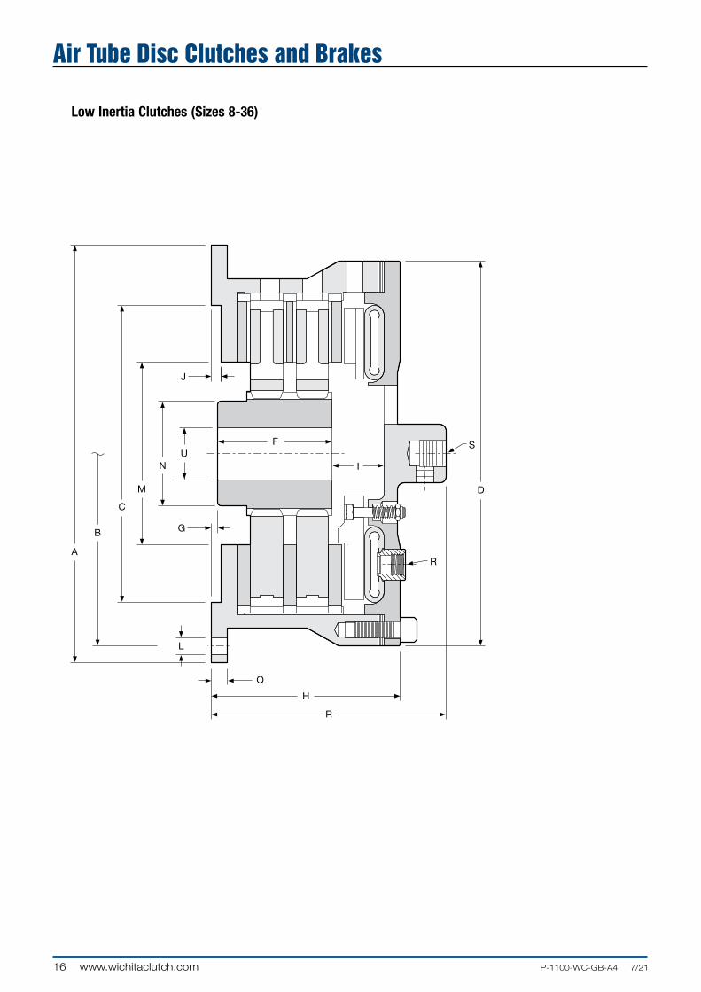
Size 6
Size 42-60
Low Inertia Clutches (Size 6, 42-60)
Air Tube Disc Clutches and Brakes

A
19P-1100-WC-GB-A4 7/21 www.wichitaclutch.com
Air Tube Disc Clutches and Brakes
Dimensions: mm Model Size ATD-
A B Hole Circle
C(1) D E F G H
LIM 104 180 165 140 184 111 22 20 79.0LIM 106 131.8 50.8 0.0 95.3LIM 206 222.3 203.20 190 223.8 163.3 82.6 1.5 127.0LIM 142 274.6 143.0 247.7LIM 242 1320.8 1250.95 1134 1244.6 369.8 190.5 25.40 342.9LIM 148 373.1 152.4 0.0 271.5LIM 248 1549.4 1473.20 1320 1441.5 484.4 222.3 25.4 382.8LIM 2601 515.6 238.3 6.4 456.9LIM 3601 1790.7 1689.10 1590 1790.7 558.8 311.2 0.0 498.6LIM 4601 717.6 473.2 6.4 689.1
(1)Dimension "C" is given as a nominal figure. The applicable tolerance is ISO H7.(Consult factory for drawing before final layout.)
Dimensions: mm Model Size ATD-
I J L M N Q RS
UNo. - Size No. - Size Min. Max.
LIM 104 17.5 4 4 x ø8.5 76 45 11 2 -1/8 NPT 5/8"-18NF 15.2 25.4
LIM 106 39.6LIM 206 38.1 1.5 4 x ø9 106.4 68.3 14.2 — 5/8"-11NF 15.2 50.8LIM 142 44.5LIM 242 92.2 6.4 24 x ø26 749.3 457.2 38.1 4 -1/2 NPT 1.5"-12NF 203.2 355.6LIM 148 93.7LIM 248 109.7 6.4 24 x M24 812.8 654.1 38.1 4 -1/2 NPT 1" NPT 254.0 457.2LIM 260(1) 156.7LIM 360(1) 131.8 6.4 24 -2"NC 914.4 685.8 — 6 -1/2 NPT 2"-12NF 279.4 482.6LIM 460(1) 162.1
(1)Less backplate. (Consult factory for drawing before final layout.)

20 www.wichitaclutch.com P-1100-WC-GB-A4 7/21
Low Inertia Clutch Air Hose Kits
Hoses from the airtube inlets (spuds) are connected to the central adaptor (spider) on the clutch into which screws the roto
coupling. For cycling duties and fastest response, silenced quick exhaust valves (SQEV's) should be used. Note, however
(a) quick exhaust valves without silencers (QEV's) can be used where noise is not a problem. (b) QEV's cannot be fitted to
models 104 to 206. For other duties elbows are supplied.
For models 106 to 208, 1 hose is adequate for low speeds. Use 2 hoses for high speeds.
Quick Exhaust Valve
The Wichita Springless Quick Exhaust Valve discharges twice as fast as any other valve tested in our laboratory and is four to five times faster than some common makes of valves.
This valve will close and seal with less than 1.5 BAR. Most others require 1.7 to 2 BAR to definitely seal. In actual tests, the Wichita Valve made many hundreds of thousands of engagements and dis en gage ments before the slightest leak occurred, or any parts needed re place ment. Other valves which were tested required major re placement in fewer than 20,000 cycles.
The Wichita Roto-coupling is a device to connect, or couple, a non-rotating air, gas, or fluid line to a rotating shaft.
Roto-couplings
Air Tube Disc Clutches and Brakes

A
21P-1100-WC-GB-A4 7/21 www.wichitaclutch.com
Quick Exhaust valve (QEV 40061-010/040) with silencer (SQEV 40061-510/540)
1/4" ROTO COUPLING PART NO. 40067-730
1/2" ROTO COUPLING PART NO. 40067-740
A
Air Tube Disc Clutches and Brakes
Air Set Coding Example: Air Set No. 333 - 18 RSQ
Quantity of Air / Quantity of fittings / Quantity of hose / App. hose length in inches
3 3 3 - 18 -
RSQ
R = roto
E = elbows
Q = QEV's
SQ = silenced QEV's
IR = integral roto
1" ROTO COUPLING PART NO. 24181-040
Model Speed of Response No. of Hoses Roto Part Number
LIM 106 slow 1 40067-730
LIM 206 fast 2 40067-730
LIM 108 slow 1 40067-740
LIM 211 fast 2 24181-014
LIM 114 slow 2 40067-740
LIM 316 fast 2 24181-040
LIM 118 slow 3 40067-740
LIM 327 fast 3 24181-045
LIM 130H slow 4 24181-040
LIM 348 fast 4 24181-049

22 www.wichitaclutch.com P-1100-WC-GB-A4 7/21
Low Inertia Brakes
Specifications
Model Slip Torque Capacity Duty Factors Max. BoreSize Nm HP/100 RPM Rect. KeyATD- 5.5 BAR 7 BAR A B C D mmLIM 104 90 113 1.6 1.2 0.6 0.3
25LIM 204 90 225 3.2 2.4 1.2 0.6 LIM 106 340 435 6.2 4.4 2.2 1.1
50LIM 206 680 870 12.5 8.8 4.4 2.2 LIM 108 620 790 11.1 8 4 2 LIM 208 1240 1580 22.2 16 8 4 57 LIM 308 1865 2375 33.3 24 12 6
LIM 111 1400 1785 25 18 9 5
LIM 211 2800 3570 50 36 18 10 64 LIM 311 4235 5390 75 54 27 15 LIM 114 2435 3100 44 31 16 8 LIM 214 4870 6200 88 62 32 16 89 LIM 314 7355 9365 132 93 48 24 LIM 116 3360 4275 60 46 24 12 LIM 216 6720 8550 120 92 48 24 102 LIM 316 10080 12825 180 139 72 36
LIM 118 5705 7260 102 75 35 21
LIM 218 11410 14520 204 150 70 42 121 LIM 318 17115 21780 306 225 105 63
LIM 121 7755 9870 139 107 55 28
LIM 221 15510 19740 277 213 111 55 152 LIM 321 23265 29610 416 320 166 83 LIM 124H 13575 17275 243 180 90 40 LIM 224H 27150 34550 487 360 180 80 152 LIM 324H 40725 51825 729 540 270 120 LIM 127 15260 19420 273 210 109 55 LIM 227 30520 38840 546 420 218 109 165 LIM 327 45780 58260 819 630 327 164 LIM 130H 29630 37710 519 380 190 100 LIM 230H 59260 75420 1038 760 380 200 184 LIM 330H 88890 113130 1557 1140 570 300 LIM 136 44920 57175 805 600 295 165 LIM 236 89840 114350 1610 1200 590 330 229 LIM 336 134760 171525 2415 1800 885 495 LIM 142 69160 81660 1150 850 425 235 LIM 242 128320 163320 2300 1700 850 470 355 LIM 342 192480 244980 3450 2550 1275 705 LIM 148 118800 151200 2225 1600 800 455 LIM 248 237600 302400 4450 3200 1600 915 455 LIM 348 356400 453600 6675 4800 2400 1365 LIM 260 473000 602000 9440 5950 3470 1940 LIM 360 709000 902300 14160 8925 5205 2910 480 LIM 460 946000 1204000 18880 11900 6940 3880 Maximum operating pressure is 8.5 BAR non cyclic / 7 BAR cyclic
Air Tube Disc Clutches and Brakes

A
23P-1100-WC-GB-A4 7/21 www.wichitaclutch.com
Air Tube Disc Clutches and Brakes
Hub & C.P. Airtube Model Balance Reg- High Volume Total Brake Hub & Center PlateSize Speed Speed Speed cm 3 Wt. Wt. J=mr 2
ATD- RPM RPM RPM* New Worn kg kg kgm 2
LIM 104 3325 5250 5250*
7 0.7 0.001
LIM 204 14.8 56 6 0.8 0.002
LIM 106 2225 3800 5700*
12 2.9 0.010
LIM 206 30 195 18 5.5 0.019
LIM 108
28 5.0 0.023
LIM 208 1675 2870 4300* 32 8.6 0.042
LIM 308 56 300
39 12.7 0.084
LIM 111
59 10.4 0.097
LIM 211 1200 2090 3125* 75 20.4 0.190
LIM 311 90 500
94 54.9 0.295
LIM 114
83 20.9 0.240
LIM 214 950 1640 2450* 106 34.9 0.464
LIM 314 125 700
132 54.9 0.704
LIM 116
115 26.8 0.430
LIM 216 835 1430 2150* 148 48.1 0.826
LIM 316 161 919
162 68.5 1.248
LIM 118
141 33.1 0.632
LIM 218 750 1270 1910* 171 54.4 1.214
LIM 318 251 1400
209 81.6 1.821
LIM 121
209 52.6 1.35
LIM 221 650 1090 1650* 261 89.8 2.57
LIM 321 300 1599
328 141.5 5.14
LIM 124H
280 60.0 2.4
LIM 224H 550 950 1410* 381 117.9 4.6
LIM 324H 490 2606
465 172.0 6.8
LIM 127
345 84.8 4.1
LIM 227 500 850 1,250* 419 149.2 8.1
LIM 327 490 2606
504 251.7 12.0
LIM 130H
441 135.2 8.0
LIM 230H 450 765 1130* 612 247.7 15.6
LIM 330H 960 5096
794 367.4 20.1
LIM 136
630 209.1 15.7
LIM 236 375 640 950* 904 321.1 30.6
LIM 336 1803 6801
1184 514.4 46.0
LIM 142
892 308 30
LIM 242 325 545 805* 1239 543 58
LIM 342 2098 7997
1680 601 76
LIM 148
1432 499 75
LIM 248 275 475 705* 2132 881 141
LIM 348 3550 13500
2966 1338 208
LIM 260
4288 1164 298
LIM 360 225 380 575* 5281 1755 448
LIM 460 8407 29300
6577 2585 635
* Consult Factory for Special Assembly Number.

24 www.wichitaclutch.com P-1100-WC-GB-A4 7/21
Low Inertia Brakes (Sizes 8-36)
Air Tube Disc Clutches and Brakes

A
25P-1100-WC-GB-A4 7/21 www.wichitaclutch.com
Air Tube Disc Clutches and BrakesDimensions: mm
Model Size ATD-
A
B Hole Circle
C (1)
Pilot D
F
G
H
LIM 108 50.8 115.8LIM 208 308.1 282.58 220 282.7 82.6 6.4 150.9LIM 111 69.9 3.3 138.2LIM 211 406.4 374.65 295 374.7 111.3 6.4 182.6LIM 114 95.3 3.3 153.9LIM 214 476.3 444.50 370 444.5 114.3 9.7 203.2LIM 116 101.6 160.3LIM 216 539.8 508.00 410 508.0 120.7 209.6LIM 316 168.4 9.7 258.8LIM 118 101.6 169.9LIM 218 590.6 558.80 470 558.8 120.7 219.2LIM 318 165.1 11.2 270.0LIM 121 101.6 187.5LIM 221 685.8 647.70 540 632.0 130.3 236.5LIM 321 181.1 19.1 298.5LIM 124H 101.6 17.5 193.8LIM 224H 762 730.25 620 736.6 130.3 19.1 252.5LIM 324H 190.5 19.1 311.2LIM 127 19.1LIM 227 831.9 800.10 700 787.4 174.8 263.7LIM 327 — — —LIM 130HLIM 230H 939.8 901.70 775 882.7 181.1 47.8 300.0LIM 330H 301.8 16.0 388.9LIM 136 143.0 241.3LIM 236 1104.9 1066.80 925 1041.4 228.6 16.0 327.2
(1) Dimension "C" is given as a nominal figure. The applicable tolerance is ISO H7.(Consult factory for drawing before final layout.)
Dimensions: mm
Model Size ATD-
J
L M
N
Q
R T
U
No.- Size No.- Size Min. Max.
LIM 108LIM 208 6.4 6 x ø14 136.7 88.9 12.7 2 - 1/2 NPT 57 25 50.8LIM 111 LIM 211 9.7 6 x ø18 177.8 101.6 16.0 2 - 1/2 NPT 82 25 63.5LIM 114LIM 214 9.7 8 x ø18 239.8 139.7 16.0 2 - 1/2 NPT 127 35.1 88.9LIM 116LIM 216 9.7 12 x ø18 266.7 152.4 16.0 2 - 1/2 NPT 155 35.1 101.6LIM 316LIM 118LIM 218 9.7 12 x ø18 317.5 177.8 16.0 3 - 1/2 NPT 196 50.8 120.7LIM 318LIM 121LIM 221 7.9 12 x ø18 368.3 228.6 19.1 3 - 1/2 NPT 235 50.8 152.4LIM 321LIM 124HLIM 224H 6.4 12 x ø18 368.3 228.6 19.1 3 - 1/2 NPT 336 50.8 152.4LIM 324HLIM 127 LIM 227 6.4 16 x ø18 412.8 228.6 19.1 3 -1/2 NPT 336 63.5 165.1LIM 327LIM 130HLIM 230H 6.4 18 x ø22 489 254 19.1 4 - 1/2 NPT 380 63.5 184.2LIM 330H LIM 136LIM 236 6.4 16 x ø18 600.2 304.8 22.4 4 - 1/2 NPT 570 152.4 228.6
(Consult factory for drawing before final layout.)
26 www.wichitaclutch.com P-1100-WC-GB-A4 7/21
Size 6
Sizes 42-60
Low Inertia Brakes (Sizes 6, 42-60)
Air Tube Disc Clutches and Brakes

A
27P-1100-WC-GB-A4 7/21 www.wichitaclutch.com
Dimensions: mmModel B C (1) Size ATD- A Hole Circle Pilot D F G HLM 106 50.8 0.0 95.3LIM 206 222.3 203.20 190 223.8 82.6 1.5 127.0LIM 142 143.0
25.40 247.7
LIM 242 1320.8 1250.95 1070 1,244.6 190.5 342.9LIM 148 152.4 0.0 271.5LIM 248 1549.4 1473.20 1320 1,441.5 222.3 25.4 382.5LIM 260 238.3
88.9 539.8
LIM 360 1790.7 1892.30 1590 1,790.7 311.2 581.2 (1) Dimension "C" is given as a nominal figure. The applicable tolerance is ISO H7.(Consult factory for drawing before final layout.)
Air Tube Disc Clutches and Brakes
Dimensions: mmModel L R USize ATD- J No.- Size M N Q No. - Size T Min. Max.LIM 106
4 x ø9
68.3
2 - 1/4 NPT
LIM 206 1.5 106.4 14.2 50.8 15.2 50.8LIM 142
24 x ø26
457.2
4 - 1/2 NPT
LIM 242 6.4 749.3 38.1 606.6 203.2 355.6LIM 248 (2) 24 x M24
654.1
4 - 1/2 NPT
LIM 348 (2) 6.4 24 x ø24 812.8 38.1 641.4 254.0 457.2LIM 260 (2)
24 x 2" NC 685.8
6 - 1/2 NPT
LIM 360 (2) 9.5 901.7 715.0 797.6 723.9 279.4 482.6(2) No flange or backplate
(Consult factory for drawing before final layout.)

28 www.wichitaclutch.com P-1100-WC-GB-A4 7/21
Low Inertia Brake Air Hose Kits
Air hose kits contain all nec es sary parts (fittings, hoses and extensions) to com plete ly plumb the brake air system.
Optional Quick Release Valves can replace elbows on most units. See pages 20 and 21.
Air sets are optional and consist of elbows (or quick exhaust valves), hoses and pipe fittings. For cycling duties and fast response time of brake engagement, elbows should be used. Customer's fast acting solonoid valve should be mounted as close as possible to the brake. For applications where fast disengagement of the brake is the main criteria the Quick Exhaust Valves should be used. Alternatively, the air supply can be piped up directly to the BSPT/NPT airtube connections (spud). Use flexible connections.
Brake Quantity of hoses Inlet Connection 'A'
104 1 1/8" BSPT male
106 1 1/4" BSPT male
108-208 1 1/2" BSPT male
111-316 2 1/2" BSPT female
118-321 3 3/4" BSPT female
124H-327 3 1 1/4" BSPT female
130H-348H 4 1 1/4" BSPT female
Hose Configurations
Hose and Inlet Connections
Air Tube Disc Clutches and Brakes

10
11
12
13
14
2019
3
2
4
1
6
7
6
7
8
24 2325
2122
A
29P-1100-WC-GB-A4 7/21 www.wichitaclutch.com
Low Inertia Clutches and Brakes
Component Parts
1. Hub
2. Demountable Back Plate
3. Socket Head Capscrews
4. Ring
6. Grooved Friction Disc (grooved on one side)
7. Center Plate
8. Grooved Friction Disc (grooved on both sides)
10. Pressure Plate
11. Airtube
12. Shims
13. Airtube Holding Plate
14. Socket Head Capscrews
19. Pressure Plate Lugs
20. Hex Head Capscrews
21. Release Springs
22. Flexloc Nuts
23. Roto-coupling
24. “O” Ring
25. Snap Ring
Air Tube Disc Clutches and Brakes

30 www.wichitaclutch.com P-1100-WC-GB-A4 7/21
Floating Plate
Hub
Ductile Center Plate
Grooved Friction Disc
Demountable Backplate (Optional)
Pressure Plate
Airtube Holding Plate
Roto-coupling
High Torque Air-Tube
Selection RequirementsTo properly select a High Torque Clutch and Low Inertia Brake, the following information must be determined.
1. Torque necessary to do the work (clutch)
2. Rotating inertia to be stopped and started
3. Heat generated by each stop/start
4. Torque necessary to stop inertia (brake)
5. Shaft size
Wichita High Torque Clutches provide the highest torque to size ratios of any Wichita Clutch. They provide smooth controlled starts and stops and are designed for minimum power loss due to low rotating inertia.
• Extremely fast response
• No lubrication
• High torque to size ratio
• Low rotating inertia
High Torque Clutches
Ring
Very Low Inertia Drive Plate Assembly Bonded or Riveted
Shims
Air Tube Disc Clutches and Brakes

A
31P-1100-WC-GB-A4 7/21 www.wichitaclutch.com
High Torque Clutches
Component Parts
1. Hub
2. De mount able Backplate
3. Socket Head Capscrews
4. Ring
6. Grooved Friction Disc (grooved on one side)
7. Center Plate
9. Grooved Friction Disc
10. Pres sure Plate
11. Pan cake Air Tube
12. Shims
13. Air Tube Holding Plate
14. Sock et Head Capscrews
20. Hex Head Capscrew
21. Release Springs
22. Flexloc Nut
23. Internal Roto-Coupling
24. “O” Ring
25. Snap Ring
26. Flat head Socket Capscrew
27. Slot ted Flush Nut
Air Tube Disc Clutches and Brakes

32 www.wichitaclutch.com P-1100-WC-GB-A4 7/21
High Torque Clutches
Specifications
Air Tube Disc Clutches and Brakes
Model Size ATD-
Slip Torque Capacity Nm
Duty Factors HP/100
Max. Bore Rect. Key
5.5 Bar 7 Bar A B C D mm
HTM 104 90 113 1.6 1.2 0.6 0.3 25HTM 204 180 226 3.2 2.4 1.2 0.6HTM 106 475 602 8 5.7 2.8 1.4 50HTM 206 950 1204 16 11.4 5.7 2.8HTM 108 977 1243 17 13 6 3HTM 208 1953 2486 34 25 13 6 60HTM 308 2930 3729 51 38 19 9HTM 111 2220 2825 38 28 14 7HTM 211 4440 5650 76 56 28 14 67HTM 311 6660 8475 114 84 42 21HTM 114 4261 5423 75 55 27 14 105
HTM 214 8522 10846 160 114 55 28 92
HTM 314 12783 16269 225 165 81 42 118HTM 116 6600 8400 118 91 47 24HTM 216 13200 16800 236 182 94 47 102HTM 316 19800 25200 354 272 142 71HTM 118 9321 11863 165 120 60 30HTM 218 18642 23726 330 240 120 60 120HTM 318 27963 35589 495 360 180 90HTM 121 15091 19207 270 208 108 54HTM 221 30182 38414 540 415 216 108 152HTM 321 45273 57621 810 623 324 162HTM 124 21305 27116 385 280 140 70HTM 224 42610 54232 770 560 280 140 152HTM 324 63915 81348 1155 840 420 210HTM 424 85220 108464 1540 1120 560 280HTM 127 32144 40911 575 442 230 115 165HTM 227 64288 81821 1150 884 460 230HTM 327 96432 122732 1724 1326 690 345 152
HTM 130 41722 53101 750 535 270 135 184HTM 230 83445 106203 1500 1070 540 270HTM 330 125167 159304 2250 1605 810 405 203
HTM 136 44920 57175 1555 1120 560 280 203HTM 236 89840 114350 3100 2240 1120 560HTM 336 134760 171525 4665 3360 1680 840 235
HTM 436 180383 229579 6220 4480 2240 1120 267HTM 148 209500 266637 3745 2690 1345 670HTM 248 419000 533273 7490 5380 2690 1345 455HTM 348 628500 799910 11235 8070 4035 2010
Maximum Air Pressure is 7 BAR.

A
33P-1100-WC-GB-A4 7/21 www.wichitaclutch.com
Air Tube Disc Clutches and Brakes
Model Size ATD-
Slip Torque Capacity Nm
Duty Factors HP/100
Max. Bore Rect. Key
5.5 Bar 7 Bar A B C D mm
HTM 104 90 113 1.6 1.2 0.6 0.3 25HTM 204 180 226 3.2 2.4 1.2 0.6HTM 106 475 602 8 5.7 2.8 1.4 50HTM 206 950 1204 16 11.4 5.7 2.8HTM 108 977 1243 17 13 6 3HTM 208 1953 2486 34 25 13 6 60HTM 308 2930 3729 51 38 19 9HTM 111 2220 2825 38 28 14 7HTM 211 4440 5650 76 56 28 14 67HTM 311 6660 8475 114 84 42 21HTM 114 4261 5423 75 55 27 14 105
HTM 214 8522 10846 160 114 55 28 92
HTM 314 12783 16269 225 165 81 42 118HTM 116 6600 8400 118 91 47 24HTM 216 13200 16800 236 182 94 47 102HTM 316 19800 25200 354 272 142 71HTM 118 9321 11863 165 120 60 30HTM 218 18642 23726 330 240 120 60 120HTM 318 27963 35589 495 360 180 90HTM 121 15091 19207 270 208 108 54HTM 221 30182 38414 540 415 216 108 152HTM 321 45273 57621 810 623 324 162HTM 124 21305 27116 385 280 140 70HTM 224 42610 54232 770 560 280 140 152HTM 324 63915 81348 1155 840 420 210HTM 424 85220 108464 1540 1120 560 280HTM 127 32144 40911 575 442 230 115 165HTM 227 64288 81821 1150 884 460 230HTM 327 96432 122732 1724 1326 690 345 152
HTM 130 41722 53101 750 535 270 135 184HTM 230 83445 106203 1500 1070 540 270HTM 330 125167 159304 2250 1605 810 405 203
HTM 136 44920 57175 1555 1120 560 280 203HTM 236 89840 114350 3100 2240 1120 560HTM 336 134760 171525 4665 3360 1680 840 235
HTM 436 180383 229579 6220 4480 2240 1120 267HTM 148 209500 266637 3745 2690 1345 670HTM 248 419000 533273 7490 5380 2690 1345 455HTM 348 628500 799910 11235 8070 4035 2010
Maximum Air Pressure is 7 BAR.
Max. Speed AirtubeModel Balance Reg- High Volume Total Clutch Hub & Center PlateSize Speed Speed Speed cm3 Wt. J=mr2 Wt. J=mr2
ATD- RPM RPM RPM New Worn kg kgm2 kg kgm2
HTM 104 NA 2100 2600* 5 0.018 0.7 0.001HTM 204 21.3 82 6 0.023 1.8 0.002HTM 106 NA 2100 2600* 10 0.059 2.9 0.010HTM 206 49 229 20 0.131 5.7 0.021HTM 108 50 0.903 6.8 0.057HTM 208 1675 1890 2500 67 1.211 13.6 0.110HTM 308 82 492 64 1.265 18.4 0.169HTM 111 60 1.14 10.4 0.097HTM 211 1200 1430 2200* 77 1.43 20.4 0.190HTM 311 131 787 94 2.19 54.9 0.295HTM 114 54 1.31 21.8 0.236HTM 214 950 1225 1930* 120 2.95 35.4 0.472HTM 314 197 1,229 127 3.04 14.1 0.637HTM 116 107 3.54 22.7 0.346HTM 216 835 1080 1700* 134 4.43 48.5 0.826HTM 316 164 918 162 5.06 68.5 1.206HTM 118 170 7.67 36.3 0.658HTM 218 950 985 1530* 220 8.43 53.5 1.214HTM 318 295 1,655 240 10.54 81.6 1.897HTM 121 253 14.08 45.8 1.31HTM 221 650 850 1400* 316 18.00 89.8 2.57HTM 321 623 3,294 343 16.86 131.5 5.14HTM 124 318 20.99 60.8 2.4HTM 224 550 765 1210* 417 26.77 117.9 4.6HTM 324 819 4,097 540 36.09 175.1 6.9HTM 424 586 38.66 211.4 8.8HTM 127 449 33.1 76.2 4.1HTM 227 500 700 1090* 541 40.8 137.9 8.1HTM 327 1000 5293 641 49.9 206.4 11.9HTM 130 692 77.4 123.4 7.8HTM 230 450 620 1000* 873 102.2 240.0 15.6HTM 330 1311 6473 1016 114.7 362.9 20.9HTM 136 993 153.9 170.6 15.5HTM 236 375 525 800* 1270 185.1 340.2 31.8HTM 336 1966 12618 1461 205.1 547.0 48.1HTM 436 1494 205.6 645.9 60.3HTM 148 3323 1084 776 77HTM 248 275 380 580* 3854 1195 904 144HTM 348 3277 23434 4431 1349 1228 207
* Consult Factory for Special Assembly Number.

34 www.wichitaclutch.com P-1100-WC-GB-A4 7/21
High Torque Clutches (Sizes 4-24)
Air Tube Disc Clutches and Brakes

AA
35P-1100-WC-GB-A4 7/21 www.wichitaclutch.com
Air Tube Disc Clutches and Brakes
Dimensions: mm
Model Size ATD-
A
B Hole Circle
C (1)
Pilot D
E
F
G
H
HTM 104(3) 85.9 25.4 1.5 63.5HTM 204(3) 187.5 174.63 110 162.1 63.5 47.8 0.0 81.0HTM 106(4) 127.8 50.8 0.0 115.1HTM 206 222.3 203.20 190 223.8 158.8 82.6 1.5 146.1HTM 108(2) 157.7 38.1 12.7 111.0HTM 208(2) 308.1 282.58 220 282.7 191.0 73.2 144.3HTM 111(2) 198.6 950.8 12.7 138.2HTM 211(2) 406.4 374.65 295 374.7 244.6 95.3 184.2HTM 114(2) 213.1 95.3 3.3 153.9HTM 214 476.3 444.50 370 444.5 266.7 114.3 9.7 200.2HTM 314(4) 254.0 114.3 9.7 200.2HTM 116 232.7 69.9 172.2HTM 216 539.8 508.00 410 508.0 283.5 120.7 9.7 220.0HTM 316 331.7 168.4 271.5HTM 118 235.7 69.9 181.9HTM 218 590.6 558.80 470 558.8 283.5 120.7 11.2 229.4HTM 318 325.4 165.1 277.9HTM 121 258.8 73.2 17.5 192.0HTM 221 685.8 647.70 540 632.0 300.5 130.3 19.1 246.1HTM 321 360.4 181.1 19.1 306.3HTM 124 255.5 88.9 9.7 212.9HTM 224 762.0 730.25 620 711.2 314.5 88.9 19.1 271.5HTM 324 373.1 130.3 19.1 330.2HTM 424(4) 736.6 679.5 650 711.2 397.3 212.9 18.3 350.8
(1) Dimension “C” is given as a nominal figure. The applicable tolerance is ISO H7. (Consult factory for drawing before final layout.)
Dimensions: mm
Model Size ATD-
I
J
L M
N
Q
S
U
No.- Size Min. Max.
HTM 104 9.7HTM 204 16 3.3 — 73.2 65.5 9.7 5/8-18NF 12.7 25HTM 106 23.9HTM 206 20.8 1.5 4 x ø9 106.4 68.3 14.2 5/8-18NF 25 50.8HTM 108 20.6HTM 208 19.1 6.4 6 x ø14 136.7 91.9 12.7 1/4 NPT 25 60.5HTM 111 26.9HTM 211 28.4 9.7 6 x ø18 177.8 104.6 28.7 1/2 NPT 25 66.8HTM 114 26.9 9.7 8 x ø18 239.8 142.7 28.7HTM 214 20.6 9.7 8 x ø18 239.8 139.7 16.0 1/2 NPT 35.1 92.2HTM 314 23.9 3.3 8 x 5/8-11NC 241.3 169.2 — 117.6HTM 116 31.8 ø18HTM 216 31.8 9.7 12 x ø18 266.7 152.4 16.0 1/2 NPT 35.1 101.6HTM 316 28.7 ø18HTM 118 ø18HTM 218 36.6 9.7 12 x ø18 317.5 177.8 16.0 1/2 NPT 50.8 120.7HTM 318 ø18HTM 121 38.1 ø18HTM 221 33.3 7.9 12 x ø18 368.3 228.6 19.1 1/2 NPT 50.8 152.4HTM 321 36.6 ø18HTM 124 28.7 ø18HTM 224 35.1 6.4 12 x ø18 368.3 228.6 19.1 1/2 NPT 50.8 152.4HTM 324 39.6 ø18HTM 424 (4) 39.6 3.3 12 x 5/8-11NC 368.3 228.6 — 1/2 NPT 50.8 152.4
(2) Non-Ventilated center plate, “center plate is solid”. (3) Drive plate assembly, “friction material is attached to a drive plate”. (4)
Less backplate. (Consult factory for drawing before final layout.)

36 www.wichitaclutch.com P-1100-WC-GB-A4 7/21
High Torque Clutches (Sizes 27-48)
Air Tube Disc Clutches and Brakes

AA
37P-1100-WC-GB-A4 7/21 www.wichitaclutch.com
Air Tube Disc Clutches and Brakes
Dimensions: mm
Model Size ATD-
A
B Hole Circle
C(1)
Pilot D
E
F
G
H
HTM 127 262.6 88.9 215.9HTM 227 831.9 800.10 700 787.4 323.9 139.7 19.1 277.1HTM 327 390.9 201.7 338.8HTM 130 290.6 108.0 255.5HTM 230 939.8 901.70 775 917.7 374.7 190.5 19.1 339.9HTM 330 412.8 241.3 384.3HTM 136 301.8 104.9 28.7 295.4HTM 236 1104.9 1066.80 925 1054.1 388.9 190.5 28.7 382.5HTM 336 476.3 273.1 31.8 469.9HTM 436(2) 1044.4 1009.7 960 1044.4 414.3 226.1 26.9 431.8HTM 148 1525.0 1473.2 1498.6 671.6 152.4 25.4 435.1HTM 248 1574.8 1524.0 1320 1447.8 765.0 222.3 44.5 528.6HTM 348(2) 1525.0 1473.2 1498.6 595.4 320.8 0.0 595.4
(1) Dimension “C” is given as a nominal figure. The applicable tolerance is ISO H7. (Consult factory for drawing before final layout.)
Dimensions: mm
Model Size ATD-
I
J
L M
N
Q
S
U
No.- Size Min. Max.
HTM 127 38.1 266.7 1/2 NPT 165.1HTM 227 41.4 6.4 16 x ø18 412.8 266.7 19.1 1 NPT 63.5 165.1HTM 327 41.4 228.6 1-1/2 -12NF 152.4HTM 130 35.1 279.4 1/2 NPT 184.2 HTM 230 35.1 6.4 18 x ø22 489 279.4 19.1 1/2 NPT 63.5 184.2HTM 330 25.4 304.8 1-1/2 -12NF 203.2HTM 136 304.8 203.2HTM 236 38.1 6.4 18 x ø26 600.2 304.8 38.1 1/2 NPT 152.4 203.2HTM 336 14 - 3/4-10NC 355.6 235.0HTM 436(2) 48.5 4.8 4 - 1.00” Pins 603.3 404.4 — 1/2 NPT 152.4 266.7HTM 148 68.6 44.5HTM 248 87.4 6.4 24 x M36 812.8 654.1 38.1 2 NPT 152.4 457.2HTM 348(2) 100.6 5.8 24 x M36 809.8 609.6 38.1 2-1/2 NPT 152.4 457.2
(2) Less backplate. (Consult factory for drawing before final layout.)

38 www.wichitaclutch.com P-1100-WC-GB-A4 7/21
Wichita Spring-Set Air Release Brakes are ideal for fail to brake on condition protection of process equipment. Constructed of high strength cast iron, this improved design has thick friction discs for longer wear life. The fast acting airtube design assures quick, smooth stops.
• No lubrication
• No adjustment
• Available in vertical mount
• Quick, simple installation
Selection requirements
The selection of a Low Inertia Brake is based on:
1. Torque required to stop a load
2. Friction area necessary to absorb rotational energy
3. Contact velocity of rotating discs
4. Maximum bore capacity of unit
Shims Airtube
Airtube Holding Plate
Hub
Center Plates
Friction Discs
Demountable Backplate (Optional)
Spring-Set Air Release BrakesVery Low Inertia Drive Plate Assembly Bonded or Riveted
Ring
Air Tube Disc Clutches and Brakes

A
39P-1100-WC-GB-A4 7/21 www.wichitaclutch.com
Component Parts 1. Hub
2. Backplate
3. Socket Head Capscrews
4. Ring
5. Springs
6A. Grooved Friction Disc (grooved on one side)
6B. Grooved Friction Disc (grooved on both sides)
7. Center Plate
11. Airtube
12. O. D. Shims
13. Air Tube Holding Plate
14. Socket Head Capscrews
15. I.D. Shims
16. Spring Release Plate
17. Airtube Spring Plate
18. Socket Head Capscrews
Low Inertia Spring-Set Brake Component Parts
Spring-Set Brake Air Hose Kits
Air hose kits contain all nec es sary parts (fittings, hoses and extensions) to com plete ly plumb the brake air system.
Optional Quick Release Valves can replace elbows on most units (see pages 20 and 21).
Hose Configurations
Air Tube Disc Clutches and Brakes

40 www.wichitaclutch.com P-1100-WC-GB-A4 7/21
Spring-Set Brakes
Specifications
Air Tube Disc Clutches and Brakes
Model Slip Torque Capacity Max. BoreSize Nm Rect. KeyATD- 4.5 BAR 5.5 BAR 7 BAR (mm)SSM 104H 25SSM 106 251 328 418SSM 206 486 633 813 50SSM 306 650 836 1022SSM 108 418 542 700SSM 208 802 1028 1356 57SSM 308 994 1277 1514SSM 111 926 1186 1311SSM 211 1763 2260 2508 64SSM 311 2181 2813 3209SSM 114 1638 2101 2791SSM 214 3118 4000 5231 89SSM 314 4067 5050 6090SSM 116 2181 2689 3209SSM 216 3988 5050 6033 102SSM 316 5593 7073 8474SSM 118 3548 4564 5830SSM 218 6779 8700 11298 120SSM 318 9140 11524 13784SSM 121 4327 5355 6485SSM 221 8101 10033 12157 152SSM 321 11321 14021 16992SSM 124H 8530 9784 —SSM 224H 15478 18213 — 152SSM 324H 20212 25263 —SSM 127 8508 10643 12812SSM 227 15919 19907 23963 165SSM 327 22223 27782 33443SSM 130H 18326 23918 29432SSM 230H 35024 45701 55982 184SSM 330H 44684 56050 66648SSM 136H 28754 33894 44193 229SSM 236H 53949 63722 85866 254SSM 336H 76263 94916 114405 254SSM 436H 98158 122167 147260 254SSM 142 48017SSM 242 89933 355SSM 342 121116SSM 148 78889SSM 248 150830 455SSM 348 195006SSM 260 367755SSM 360 555982 460SSM 460 605016
* Not the standard 4.13 BAR/60 PSI release pressure. Consult Factory.By choice a lower spring force unit is less stressed therefore preferred.

A
41P-1100-WC-GB-A4 7/21 www.wichitaclutch.com
Air Tube Disc Clutches and Brakes
Hub & Center Plate AirtubeModel Balance Reg- High Volume Total Clutch Hub & Center PlateSize Speed Speed Speed cm3 Wt. Wt. J=mr2
ATD- RPM RPM RPM New Worn kg kg kgm2
SSM 104H 3325 5250 5250* 22 86 7 0.7 0.001SSM 106 12 2.9 0.010SSM 206 2225 3800 5700*SSM 306 30 195 18 5.5 0.019 SSM 108 28 5.0 0.023SSM 208 1675 2870 4300* 32 8.6 0.042SSM 308 56 300 39 12.7 0.084SSM 111 59 10.4 0.097SSM 211 1200 2090 3125* 75 20.4 0.190SSM 311 90 500 94 54.9 0.295SSM 114 83 20.9 0.240SSM 214 950 1640 2450* 106 34.9 0.464SSM 314 125 700 132 54.9 0.704SSM 116 115 26.8 0.430SSM 216 835 1430 2150* 148 48.1 0.826SSM 316 161 919 162 68.5 1.248SSM 118 141 33.1 0.632SSM 218 750 1270 1910* 171 54.4 1.214SSM 318 251 1400 209 81.6 1.821SSM 121 209 52.6 1.35SSM 221 650 1090 1650* 261 89.8 2.57SSM 321 300 1599 328 141.5 5.14SSM 124H 280 60.0 2.4SSM 224H 550 950 1410* 381 117.9 4.6SSM 324H 490 2606 465 172.0 6.8SSM 127 345 84.8 4.1SSM 227 500 850 1250* 419 149.2 8.1SSM 327 490 2606 504 251.7 12.0SSM 130H 441 135.2 8.0SSM 230H 450 765 1130* 612 247.7 15.6SSM 330H 960 5096 794 367.4 20.1SSM 136H 630 209.1 15.7SSM 236H 375 640 950* 904 321.1 30.6SSM 336H 1803 6801 1184 514.4 46.0SSM 436H 1826 697 61.4SSM 142 892 308 30SSM 242 325 545 805* 1239 543 58SSM 342 2098 7997 1680 601 76SSM 148 1432 499 75SSM 248 275 475 705* 2132 881 141SSM 348 3550 13500 2966 1338 208SSM 260 4288 1164 298SSM 360 225 380 575* 5281 1755 448SSM 460 8407 29300 6577 2585 635
* Consult Factory for Special Assembly Number.

42 www.wichitaclutch.com P-1100-WC-GB-A4 7/21
Spring-Set Brakes (Sizes 4H, 8-36)
Air Tube Disc Clutches and Brakes

A
43P-1100-WC-GB-A4 7/21 www.wichitaclutch.com
Dimensions: mm Model B C (1) Size ATD- A Hole Circle Pilot D E F G H SSM 104H
105 25
1.6
96 180 165 140 180 SSM 108 149.4 50.8
6.4 115.8
SSM 208 308.1 282.58 220 282.7 182.6 82.6 150.9SSM 111 166.6 69.9 3.3 138.2SSM 211 406.4 374.65 295 374.7 217.4 111.3 6.4 184.2SSM 114
203.2 76.2 3.3 152.4
SSM 214 251.2 114.3 9.7 198.4SSM 314
476.3 444.50 370 444.5 297.7 165.1 9.7 246.1
SSM 116
209.6 101.6 152.4SSM 216 255.5 120.7 9.7 199.9SSM 316
539.8 508.00 410 508.0 308.1 168.4 251.0
SSM 118
228.6 101.6 11.2 166.6SSM 218 271.8 120.7 11.2 214.6SSM 318
590.6 558.80 470 558.8 — —- — —
SSM 121
241.6 101.6 19.1 187.5SSM 221 301.8 130.3 19.1 243.1SSM 321
685.8 647.70 540 632.0 — — — —
SSM 124H
242.8 101.6 19.1 165.1SSM 224H 301.8 130.3 20.6 241.3SSM 324H
762 730.25 620 736.6 — — — —
SSM 127
252.5 114.3 195.3SSM 227 317.5 174.8 19.1 257.3SSM 327
831.9 800.10 700 787.4 387.4 201.7 319.0
SSM 130H
279.4 127.0 16 211.1SSM 230H 374.7 181.1 47.8 298.5SSM 330H
939.8 901.70 775 882.7 — — — —
SSM 136H
298.5 108.0 16 217.4SSM 236H 384.3 228.6 16 304.8SSM 336H
1104.9 1066.80 925 1041.4 484.1 314.5 25.4 401.6
Dimensions: mmModel L R USize ATD- J No. - Size M N Q No. - Size S T Min. Max.
SSM 104H 4.7 4 - ø9
2 - 1/8 NPT
76 50 54 180 50 15 25SSM 108
6.4 6 x ø18
2 - 1/2 NPT
SSM 208 136.7 88.9 12.7 238.3 52.3 25 50.8SSM 111
9.7 8 x ø18
2 - 1/2 NPT
SSM 211 177.8 101.6 16 303.3 76.7 25 63.5SSM 114
SSM 214 9.7 8 x ø18 2 - 1/2 NPT 98 SSM 314
239.8 139.7 16
365.3
35.1 88.9
SSM 116
SSM 216 9.7 12 x ø18 2 - 1/2 NPT SSM 316
266.7 152.4 16
414 111.3 35.1 101.6
SSM 118 9.7
SSM 218 9.7 12 x ø18 3 - 1/2 NPT SSM 318
317.5 177.8 16
492.3 124 50.8 120.7
SSM 121 7.9
SSM 221 7.9 12 x ø18 3 - 1/2 NPT SSM 321
368.3 228.6 19.1
541.3 158.8 50.8 152.4
SSM 124H 6.4
SSM 224H 6.4 12 x ø18 3 - 1/2 NPT SSM 324H
368.3 228.6 19.1
673.1 209.6 50.8 152.4
SSM 127
SSM 227 6.4 16 x ø18 3 - 1/2 NPT SSM 327
412.8 228.6 19.1
685.8 209.6 63.5 165.1
SSM 130H 6.4
SSM 230H 6.4 18 x ø22 4 - 1/2 NPT SSM 330H
489 254 19.1
811.3 209.6 63.5 184.2
SSM 136H
SSM 236H 6.4 18 x ø22 4 - 1/2 NPT SSM 336H
600.2 304.8 22.4 971.6 323.9 152.4 228.6
(Consult factory for drawing before final layout.)
(1) Dimension "C" is given as a nominal figure. The applicable tolerance is ISO H7. (Consult factory for drawing before final layout.)
A
Air Tube Disc Clutches and Brakes

44 www.wichitaclutch.com P-1100-WC-GB-A4 7/21
Spring-Set Brakes (Sizes 6, 42-48)
Size 6
Sizes 42-48
Air Tube Disc Clutches and Brakes

A
45P-1100-WC-GB-A4 7/21 www.wichitaclutch.com
Dimensions: mm Model B C (1) Size ATD- A Hole Circle Pilot D E F G HSSM 106 138.9 50.8 0.0 107.2SSM 206 222.3 203.20 190 223.8 169.2 82.6 1.5 138.2SSM 142 311.9 143.0
25.40 246.1
SSM 242 1320.8 1250.95 1070 1244.6 407.2 190.5 341.4SSM 148 381.0 152.4 0.0 284.2SSM 248 1549.4 1473.20 1220 1441.5 491.0 222.3 25.4 393.7SSM 260(2) 566.7 238.3
6.40 447.3
SSM 360(2) 1790.7 1689.10 1600 1790.7 682.8 358.9 565.2 (1) Dimension "C" is given as a nominal figure. The applicable tolerance is ISO H7. (Consult factory for drawing before final layout.)
Air Tube Disc Clutches and Brakes
Dimensions: mm
Model L R USize ATD- J No. - Size M N Q No. - Size S T Min. Max.SSM 106
4 x ø9
2 - 1/4 NPT —
SSM 206 1.5 106.4 68.3 14.2 50.8 15.2 50.8SSM 142
24 x ø26
4 - 1/2 NPT
SSM 242 6.4 749.3 457.2 26.9 1102.9 519.2 203.2 355.6SSM 148
24 x ø26
4 - 1/2 NPT
SSM 248 6.4 812.8 654.1 38.1 1324.1 482.6 254.0 457.2SSM 260(2)
24 - 4.5" NC
— 6 - 1/2 NPT
SSM 360(2) 6.4 914.4 685.8 1562.1 524.0 279.4 482.6 (2) Less backplate. (Consult factory for drawing before final layout.)

46 www.wichitaclutch.com P-1100-WC-GB-A4 7/21
Mounting EaseThree bolts mount the brake to the arm of the mill roll stand or machine frame and an optional pilot location makes fitting to both new and existing ma chines a simple operation.
Wear IndicatorA brake wear in di ca tor, which is con ve nient ly lo cat ed for easy visual in spec tion, means no down time to check re main ing friction material life.
Easy ConnectionAir and electrical connections are easily accessible for fast, simple installation and mainte nance.
SafetyMistral’s integral
guard ing elim i nates the cost and effort of installing external guards. Op er a tor safety is further en hanced by au to mat ic air and electric disconnects when the front cover is removed.
Compact Design, Modern StylingMistral brakes are compact at only 29.46mm or 40.89mm in diameter. Their size facilitates the pickup of small, part reels used in short batch runs. For automatic reel loading machines, Mistral offers optional infrared and speed sensor installation within the brake. Their modern, industrial styling enhances the appearance of any ma chine on which they are used.
Fine TuningEach brake may be specified with a varying number of pneumatic actuators, allowing precise selection of brake torque capacity for optimum tension control.
Wichita Mistral pneumatic tension brake is attuned to the needs of the corrugating market for which it was originally de signed. It is also a versatile product which is
finding favour in ad ditional tensioning ap plications. Wichita de signers and en gineers consulted ex tensively with mill roll stand manufacturers and users to offer a tension brake ideally
suited to the needs of this particular market. The result is a compact, high performance, ver sa tile brake ca pa ble of handling the tensioning needs of the latest ma chine designs, as well as existing equipment. The Mistral paves the way for in creas ing line speeds by 164 cm/sec. from 810 ft./min. (or slower) to 1,140 ft./min.
Mistral Tension Brakes
Tension Brakes
OBSO
LETE
OBSO
LETE
OBSO
LETE
OBSO
LETE

B
47P-1100-WC-GB-A4 7/21 www.wichitaclutch.com
Front Cover RemovalBy removing just three cap screws, the Mistral’s front cover can be detached for easy and fast access to internal parts. Cover re mov al au to mat i cal ly dis con nects both air and electricity.
Integral CoolingA rugged, high per for mance, low energy us age fan is housed within the brake for high heat dissipation - a must for in creased pro duc tiv i ty through con trolled tension at many roll speeds.
Performance Curve
Fan Data and Connection Data
Model Fan Voltages Fan Power Electric Pneum.
220 VAC or/order M16 1/8 BSP 200 110 VAC or/order 20W PG9 1/8 BSP 24 VDC 3/8 NPT 1/8 NPT
220 VAC or/order M16 1/8 BSP 280 110 VAC or/order 18W PG9 1/8 BSP 24 VDC 3/8 NPT 1/8 NPT
From the air cooled Modevo to the renowned Kopper Kool range, Wichita has a brake to suit all tension control duties in converting applications. For optimum control, including flying splice operations, we offer the modular Altra range of tension controllers. Please contact your Wichita representative to find out more and to request a copy of our Tension Control Systems catalogue, or visit wichita.co.uk and look at our product range, then choose Tension Products.
Altra Sonic Altra EasyAltra Steady
Hours
Paper Length
Improved production
using a Mistral brake
B
Wichita Tension Products - order or see Tension Control Systems Catalogue
Tension Brakes
Mistral Brakeat 1,140 ft./min.
Current Brakeat 810 ft./min.
Tension Brakes
OBSO
LETE
OBSO
LETE
OBSO
LETE
OBSO
LETE

48 www.wichitaclutch.com P-1100-WC-GB-A4 7/21
ModEvo Tension Brakes
The ModEvo brake disc was developed at the Bedford, UK factory using Finite Element Analysis techniques to ensure maximum strength with minimum weight. The design is optimized to make best use of the cooling air available at slow speeds, and being bidirectional, it achieves high heat dissipation capacity in either rotational direction. An optional electric cooling fan is available where space is limited or more extreme heat handling is required.
Available in five sizes: 250 mm, 300 mm, 350 mm, 400 mm and 450 mm diameters, all discs are the same thickness and use the same brake modules and actuators. Each disc can be specified with a minimum of a single module, up to the maximum number of modules that can be fitted
Brake Discs and Coolingaround the disc. This allows torque-handling capabilities ranging from a maximum of 893 Nm for the 250 mm disc, up to 4313Nm for the 450 mm disc.
NOTE: If using a high speed ductile iron disc the catalog heat rating should be reduced by 10% as the thermal con-ductivity of the ductile iron is less than grey cast iron.
Maximum Rotational Speed
Disc Standard High Diameter Speed Speed mm rev./min. rev./min.
250 2,250 3,375
300 1,900 2,850
350 1,650 2,475
400 1,450 2,175
450 1,250 1,875
Tension Brakes Air Cooled
60%
25%
100%
B
49P-1100-WC-GB-A4 7/21 www.wichitaclutch.com
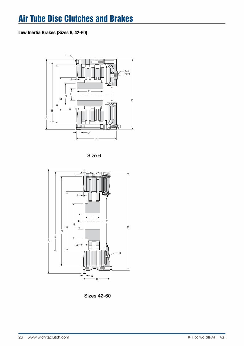
Newly developed rolling diaphragm actuators are used in ModEvo, producing more force than previous designs to allow higher torque ratings. However, the sensitivity for which rolling diaphragms are favoured is not compromised. Three actuator options are available, offering clamping forces of 100%, 60% or 25%.
The finned, die cast aluminum brake module is common to all brake disc diameters. Each module houses two pairs of actuators, and allows friction pads to be changed quickly without dismantling the module.
Actuator Options
60%
25%
100%
The optional guard has a plastic front with ‘ModEvo’ molded in and a metal ventilated perimeter.
Mounting is by four brackets on customer’s machine frame.
The centre of the guard is designed such that it may be cut-out by customer to suit the diameter of the shaft in through-shaft installations.
Optional Guard
ModEvo 300/8 with Fan
Brake Size 24v 115v 230v(fan Diameter) DC AC AC
250 (150 mm) Yes Yes Yes
300 (150 mm) Yes Yes Yes
350 (150 mm) Yes Yes Yes
400 (150 mm) Yes Yes Yes
(200 mm) not available Yes Yes
450 (150 mm) Yes Yes Yes
(200 mm) not available Yes Yes
(250 mm) not available Yes Yes
Other low cost guards are also available.
The mesh guard below is designed to fit the Modevo 250mm and 350mm. It has a sturdy welded steel construction.
Tension Brakes Air Cooled

50 www.wichitaclutch.com P-1100-WC-GB-A4 7/21
Coupling Clutches
The Wichita Standard Vent Com bi na tion Clutch-Coupling is designed for reliable in-line power transmission. The simple air-tube design, with small air vol ume, speeds en gage ment and dis en gage ment. It is un af fect ed by centrifugal force and has no self-energization like drum clutch de signs. Ideally suited for large inertia loads where smooth controlled starts are needed.
Grinding Mill Clutches
Wichita Grinding Mill Clutches are spe cial ly designed to provide quick, smooth starts with limited current surge for heavy duty grinding mills. The clutch is adapt able to remote control allowing centralized operation through simple air or electric circuits.
Marine Clutches
The Wichita Marine Standard Vent Com bi na tion Clutch-Coupling is designed for reliable in-line power transmission. The simple air-tube design, with small air vol ume, speeds en gage ment and dis en gage ment.
It is un af fect ed by centrifugal force and has no self-energization like drum clutch de signs. Ideally suited for large inertia loads where smooth controlled starts are needed.
Standard Vent Clutches

C
51P-1100-WC-GB-A4 7/21 www.wichitaclutch.com
Field of Application Group A Group B Group C Group D
Pumps Centrifugal Reciprocating compressors Reciprocating compressors compressors over 2 cylinders, one or two cylinders centrifugal fans & blowers
Agitators Liquid Semi-solid Solids
Brick Brick press, extruder, pug mill manufacturing
Can & bottling machine Bottle-can feeders, filling, mixers
Engine driven equipment Crane, hoist, engine Crowd
Grinding mills Ball-rod-sag-pebble Crushers, shakers
Lumber processing Yarder Carriages, conveyers Chipper, logger
Marine Propulsion clutch, anchor winch Shaft brakes, propulsion reversing type
Bulk material Conveyors evenly loaded, Feeders Elevators handling line shaft evenly loaded
Metal production & Coilers, slitters, press brake, Draw bench, rolling mill, Hammer mill, forming metalforming non-geared press, geared press shear, back geared press, press, forging press, deep draw press, transfer header press, knuckle press press, toggle press
Paper industry dryer Fourdrinier to 500 FPM, Fourdrinier to 1800 RPM sections & calenders paper mill plane & press selections, calenders consult factory smoothing press & dryers
Petroleum Drilling & service rig master Mud pumps, production clutches, compound clutches, PTO clutches rotary, drum
Rubber Transfer machines Banberry mixer, drum mixer, Centrifuge manufacturing evenly loaded extruder, calender
Typical Applications Wichita Standard Vent Clutches allow smooth acceleration of coil transporter.
Wichita Grinding Mill Clutches provide shock-free
start-up of large inertia loads.
Application Guidelines
Clutch selection is made by knowing the application horse pow er/100 RPM, the available air pressure, required torque and the clutch heat horse pow er. The Re quire ments
Chart A
Table (Chart A) gives application factors ranging from light duty (the A group) to extra heavy duty (the D group).
Reliable, trouble-free Wichita Standard Vent Clutches handle maximum loads on drilling rigs.
Standard Vent Clutches

52 www.wichitaclutch.com P-1100-WC-GB-A4 7/21
Maximum speedRPM(2)
Airtube DisplacementVolume cm
3
Coupling and Grinding Mill Clutch Selection
Specifications
Chart C Dynamic Weights and Inertia Slip Torque Model capacity Nm(1) Total Unit External Parts Standard Parts Size ATD– @5.5 bar / @8.5 bar Std performance High performance Weight (kg) Inertia (kg m2) Weight (kg) Inertia (kg m2) Weight (kg) Inertia (kg m2) New Worn
SV 108 620 - 960 1750 2500 16 0.103 3.6 0.05 8 0.625 55 300
SV 208 1240 - 1920 1750 2500 26 0.155 8 0.074 8 32 55 300
SV 308 - 1750 2500 - - - - - - 55 300
SV 111 1400 - 2170 1400 2200 30 0.458 8.6 0.21 19 0.3 90 500
SV 211 2800 - 4340 1400 2200 49 0.715 16 0.43 19 0.3 90 500
SV 311 - 1400 2200 - - - - - - 90 500
SV 114H 2435 - 3765 1200 2000 68 1.55 15 0.575 35 0.775 125 700
SV 214H 4870 - 7530 1200 2000 93 1.98 26 0.985 35 0.775 125 700
SV 314H 7305 - 11295 1200 2000 118 - 37 - 35 0.775 125 700
SV 116 3360 - 5190 1200 2000 85 2.53 19 0.945 43 0.863 160 920
SV 216 6720 - 10380 1200 2000 124 3.65 41 1.93 43 0.863 160 920
SV 118 5705 - 8815 1000 1750 125 3.93 21 1.35 72 1.7 250 1400
SV 218 11410 - 17630 1000 1750 176 6.15 42 2.7 72 1.7 250 1400
SV 118H - - - - - - - - - - -
SV 218H - - - - - - - - - - -
SV 318H - - - - - - - - - - -
SV 221 15510 - 23970 900 1400 260 11.2 62 5 100 2.5 300 1600
SV 321 23265 - 35955 900 1400 360 16.3 100 7.43 100 2.5 300 1600
SV 124H 13575 - 20980 700 1100 244 14.6 41 4.15 109 3.08 490 2600
SV 224H 27150 - 41960 700 1100 343 22.4 82 8.2 109 3.08 490 2600
SV 324H 40725 - 62940 700 1100 470 27.9 130 13.3 109 3.08 490 2600
SV 227 30520 - 47170 700 1100 420 29.5 84 10.1 170 10 400 2600
SV 327 45780 - 70755 700 1100 540 39 132 15.8 170 10 400 2600
SV 230H 59260 - 91590 600 1000 624 55.4 130 19.6 250 19.5 960 5100
SV 330H 88890 - 137385 600 1000 860 80 254 38.8 250 19.5 960 5100
SV 336 134760 - 208275 560 800 1281 141 285 41.3 400 50 1800 6800
SV 342 192480 - 297480 460 900 1620 316 487 138 520 112.5 2100 8000
SV 248 237600 - 367200 400 600 2152 495 445 171 900 132.5 3550 13500
SV 348 356400 - 550800 400 600 3500 775 520 420 900 132.5 3550 13500
SV 260 473000 - 731000 340 475 3150 1013 592 325 - - 8400 29300
SV 360 709000 - 1096000 340 475 4850 1450 570 355 - - 8400 29300
SV 460 946000 - 1462000 340 475 - - - - - - 8400 29300
SV 560 - 340 475 - - - - - - - -
SV 372 1204500 - 1861500 265 400 - - - - - - - -
Note: Maximum air pressure – 7 BAR
(1) Torque Rating - Dynamic torque ratings represent the full clutch capacity. Service conditions vary but as a guide to selection for cycling application use 75% of torque rating.Air Pressure - torque is directly proportional to the air pressure supplied.(2) High Speed - maximum speed ratings may be exceeded in many applications. For advice on speed, service factors etc. consult your Wichita Engineer. Consult factory for drawing before final layout.
Standard Vent Clutches

C
53P-1100-WC-GB-A4 7/21 www.wichitaclutch.com
Standard Vent Clutches - Driving Adapters
Standard Adapter (Standard Gap) Quick Change Adapter (Access Gap)
Standard Driving AdaptersThe driving adapter is designed to allow the clutch to be used in a shaft-to-shaft or through-shaft coupling arrangement.
Quick Change AdaptersThe quick change feature, using a driving elbow piece between the driving adapter and the clutch driving ring, enables replacement of any wearing clutch part without disturbing either shaft.
Dimensions: mm +.007cm -.000cm Size A B C D D1 E F G H
8 79.375 76.2 3.175 95.25 — 3.175 263.525 244.475 225.2726
11 92.075 82.55 9.5 158.75 127 3.175 14.375 365.125 314.2234
14H 136.525 120.65 403 177.8 158.75 6.35 444.5 412.75 384.0734
18 174.625 146.05 28.6 203.2 203.2 9.525 558.8 527.05 495.1984
18H 174.625 146.05 28.6 203.2 203.2 9.525 558.8 527.05 495.1984
21 171.45 152.4 19.05 241.3 228.6 6.35 635 603.25 571.3984
24H 212.725 186 27 254 304.8 6.35 711.2 679.45 647.573
27 222.25 196.85 25.4 279.4 292.1 6.35 787.4 755.65 723.773
30H 234.95 222.25 12.7 355.6 355.6 6.35 863.6 831.85 799.973
36 266.7 254 12.7 381 355.6 6.35 1041.4 1009.65 977.773
42 279.4 254 25.4 381 381 6.35 1250.95 1200.15 1142.873
48 — 346.075 — — 508 12.7 1422.4 1371.6 1290.32
60 — 412.75 — 609.6 — 9.525 1695.45 1644.65 1593.85
Max. Bore Rect. Key Size I J J1 K L M N O
8 212.725 63.5 — 13.4874 152.4 47.625 * —
11 298.45 104.902 85.725 16.6624 203.2 50.8 63.5 —
14H 368.3 120.65 104.775 16.6624 152.4 53.975 79.375 —
18 469.9 133.35 133.35 17.4752 152.4 111.125 88.9 —
18H 469.9 133.35 133.35 17.4752 152.4 111.125 88.9 —
21 552.45 158.75 152.4 17.4752 152.4 101.6 158.75 —
24H 622.3 168.402 168.275 17.4752 152.4 131.7752 139.7 —
27 692.15 184.15 193.675 17.4752 304.8 141.3002 117.475 —
30H 774.7 234.95 234.95 17.4752 304.8 165.1 146.05 —
36 952.5 254 234.95 17.4752 406.4 200.025 104.775 —
42 1117.6 254 254 26.1874 304.8 188.9252 144.4752 —
48 — — 254 26.1874 304.8 257.175 155.575 —
60 — 457.2 — 26.1874 609.6 311.15 292.1 63.5* Consult Factory
Standard Vent Clutches

54 www.wichitaclutch.com P-1100-WC-GB-A4 7/21
Component Parts 1. Hub
2. Hex Head Bolt
3. Backplate
4. Shim
5. Driving Ring
6. Friction Disc
Coupling and Grinding Mill Clutches
7. Release Spring
8. Center Plate
9. Pressure Plate
10. Hose Assembly
11. Air Tube
12. Air Tube Holding Plate
14. Socket Head Capscrew
16. Elbow
17. Bolt (Furnished by cus tom er)
Standard Vent Clutches

C
55P-1100-WC-GB-A4 7/21 www.wichitaclutch.com
Coupling Clutches
The Wichita Standard Vent Combination Clutch-Coupling is designed for reliable in-line power transmission. The simple air-tube design, with small air volume, speeds en gage ment and dis en gage ment. It is un af fect ed by centrifugal force and has no-self-energization like drum clutch designs. Ideally suited for large inertia loads where smooth controlled starts are needed.
The Wichita air-tube disc design combines all the best features of a disc type clutch with all the advantages of direct air en gage ment.
The compact design, capable of smoothly engaging and disengaging, employs the simplest and most trouble-free method of applying air pres sure yet designed.
Demountable back plate for accessibility. (Optional)
Friction discs available in halves easily replaceable without dismounting.
Releasing springs ensure complete disengagement.
Full width moulded composition teeth on friction disc minimize wear on driving ring. Air-tube easily
replaceable without dismounting by simply removing these capscrews.
All air connections on outside for easy access.
Optional high speed air tube reinforced to withstand speeds even greater than permissible with cast iron.
In-line power applications
Smooth, controlled acceleration
Unaffected by centrifugal force
Standard Vent Clutches

56 www.wichitaclutch.com P-1100-WC-GB-A4 7/21
Coupling Clutches
Standard Vent Clutches
U - Tap or Drill SizeV - No. of Holes
Y - Pipe Size Air ConnectionZ - No. of Holes
W - Air Connection Hole Center
AA - Thread for External Roto- Coupling
Wichita QuickRelease ValveAvailable
1/2"NPT

C
57P-1100-WC-GB-A4 7/21 www.wichitaclutch.com
Dimensions: mm Model Max Bore Size Rect. Key ATD– A B C D E F G H I J 108 SV 244 225.5 215.9 203.2 203.2 49 69.85 49 168.27 244 208 SV 244 225.5 215.9 203.2 203.2 49 104.77 49 168.27 244 308 SV 244 225.5 215.9 203.2 203.2 49 139.7 49 168.27 244 111 SV 340 314.4 304.8 279.4 279.4 75 76.2 76 215.9 303 211 SV 340 314.4 304.8 279.4 279.4 75 107.95 76 215.9 303 311 SV 340 314.4 304.8 279.4 279.4 75 141.3 76 215.9 303 114H SV 413 384.25 372.6 355.6 238.12 83 109.5 115 317.5 413 214H SV 413 384.25 372.6 355.6 238.12 83 146.05 115 317.5 413 314H SV 413 384.25 372.6 355.6 238.12 83 182.57 115 317.5 413 118 SV 527 495.4 476.25 457.2 292.1 90 120.65 133 355.6 492 218 SV 527 495.4 476.25 457.2 292.1 90 158.75 133 355.6 492 118H SV 527 495.4 476.25 457.2 292.1 90 120.65 133 406.4 549 218H SV 527 495.4 476.25 457.2 292.1 90 158.75 133 406.4 549 318H SV 527 495.4 476.25 457.2 292.1 90 196.85 133 406.4 549 321 SV 527 571.5 552.45 533.4 355.6 115 231.77 178 406.4 549 124H SV 679 571.5 628.65 533.4 406.4 115 149.22 178 533.4 686 224H SV 679 571.5 628.65 533.4 406.4 115 184.15 178 533.4 686 324H SV 679 571.5 628.65 533.4 406.4 115 238.12 178 533.4 686 327 SV 679 724 704.85 685.8 495.3 190 247.65 229 533.4 686 230H SV 832 800.1 781.05 762 571.5 152 215.9 229 628.65 822 330H SV 832 800.1 781.05 762 571.5 152 292.1 229 628.65 822 336H SV 1010 978 952.5 914.4 711.2 229 320.67 343 774.7 972 342 SV 1200 1143 1117.6 1066.8 1066.8 254 301.62 533 889 1121 248 SV 1372 1320.8 1295.4 1219.2 889 305 276.22 533 1016 1305 348 SV 1372 1320.8 1295.4 1219.2 889 305 346 533 1016 1330 260 SV 1645 1594 1574.8 1524 917.6 - 412.75 575 1181.1 1562 360 SV 1645 1594 1574.8 1524 917.6 - 508 575 1181.1 1562 460 SV 1645 1594 1574.8 1524 917.6 - 596.9 575 1181.1 1562(1) Dimension "C" is given as a nominal figure. The applicable tolerance is ISO H7. (Consult factory for drawing before final layout.)
Model Size ATD– K L M N P R S T U V W X Y Z
108 SV 210 102 19.05 — 11.12 264 35 12.7 6xM12 6 57.1 12.7 1/2 50.8 208 SV 210 137 19.05 44.4 11.12 264 70 12.7 6xM12 6 57.1 12.7 1/2 50.8 308 SV 210 168 19.05 77.8 11.12 264 38 12.7 6xM12 6 57.1 12.7 1/2 50.8 111 SV 299 102 22.225 — 12.7 365 38 12.7 8xM16 8 63.5 11.12 1/2 50.8 211 SV 299 138 22.225 44.4 12.7 365 73 12.7 8xM16 8 63.5 11.12 1/2 50.8 311 SV 299 171 22.225 76.2 12.7 365 107 12.7 8xM16 8 63.5 11.12 1/2 50.8 114H SV 367 129 28.575 — 15.87 445 48 15.8 6xM16 6 57.1 19.05 1/2 50.8 214H SV 367 165 28.575 50.8 15.87 445 83 19 6xM16 6 57.1 19.05 1/2 50.8 314H SV 367 203 28.575 85.7 15.87 445 120 19 6xM16 6 57.1 19.05 1/2 50.8 118 SV 477 143 33.3502 — 15.87 559 49 19 6xM16 6 62 25.4 1/2 76.2 218 SV 477 181 33.3502 53.9 15.87 559 89 19 6xM16 6 62 25.4 1/2 76.2 118H SV 477 143 33.3502 — 15.87 559 49 19 6xM16 6 62 25.4 1/2 76.2 218H SV 477 185 33.3502 53.9 15.87 559 89 19 6xM16 6 62 25.4 1/2 76.2 318H SV 477 221 33.3502 95.2 15.87 559 130 19 6xM16 6 62 25.4 1/2 76.2 321 SV 543 257 41.275 107.9 19.05 635 159 25 6xM16 6 60.3 25.4 1/2 76.2 124H SV 618 167 41.275 — 22.22 711 72 19 6xM16 6 69.8 25.4 1/2 76.2 224H SV 618 221 41.275 69.8 22.22 711 114 19 6xM16 6 69.8 25.4 1/2 76.2 324H SV 618 264 41.275 117.5 22.22 711 159 19 6xM16 6 69.8 25.4 1/2 76.2 327 SV 696 265 41.275 117.5 22.22 787 165 35 12xM16 12 60.3 25.4 1/2 76.2 230H SV 771 257 41.275 95.2 31.75 864 143 35 12xM16 12 73 25.4 1/2 101.6 330H SV 771 327 41.275 158.7 31.75 864 206 35 12xM16 12 73 25.4 1/2 101.6 336H SV 944 365 49.2252 180.9 34.92 1041 232 38.1 12xM16 16 73 25.4 1/2 101.6 342 SV 1108 365 50.8 187.32 34.92 1251 244 38.1 12xM24 12 88.9 31.75 1/2 101.6 248 SV 1290 378 66.675 104.77 34.92 1441 219 50.8 12xM24 12 88.9 31.75 1/2 101.6 348 SV 1290 403 66.675 174.62 34.92 1422 251 50.8 12xM24 12 88.9 31.75 1/2 101.6 260 SV 1567 413 76.2 139.7 76.2 1695 229 63.5 12xM30 24 50.8 50.8 1/2 152.4 360 SV 1567 508 76.2 228.6 76.2 1695 330 63.5 12xM30 24 50.8 50.8 1/2 152.4 460 SV 1567 594 76.2 317.5 76.2 1695 419 63.5 12xM30 24 50.8 50.8 1/2 152.4(Consult factory for drawing before final layout.)
Standard Vent Clutches

58 www.wichitaclutch.com P-1100-WC-GB-A4 7/21
DC Units showing Split Rim Construction(on left) and dual mounting DC component parts
DC Specifications
If the size unit you are looking for is not shown in this leaflet, please ask your Wichita support office about availability.
Model Torque at 75psi and 100 RPM Overall Width Flange DiameterSize NM Max RPM mm mm DC-6-200 231 1800 74.63 273.10 DC-8-250 485 1800 87.33 327.03DC-10-300 921 1800 104.78 390.47 DC-14-400 2226 1800 132.56 498.48 DC-16-500 3977 1540 168.28 596.90 DC-18-500 4972 1400 168.28 647.70 DC-20-500 6056 1300 168.28 698.50 DC-22-500 7040 1220 168.28 749.30 DC-24-500 8475 1200 168.28 800.10DC-26-525 10441 1050 176.23 863.60 DC-28-525 11977 1000 176.23 914.40 DC-30-525 13672 950 176.23 965.20 DC-40-525 23842 740 176.23 1235.08
Drum Clutches and Brakes
Based on over 50 years experience in providing solutions to demanding power transmission challenges worldwide, we are proud to offer our customers a range of replacement elements and spares for drum type clutches and brakes. Backed by the Wichita name and our 2 year guarantee, these elements are directly interchangeable with all of the popular drum elements currently in service.
Wichita DC Drum ElementsThe DC range of constricting drum clutch and brake is commonly found throughout all industries in general power transmission duties. Constructed using an integral rim and tube actuator and with low inertia and high misalignment capacity, the DC range offers the simplest solution to less arduous clutch and brake requirements. Along with the standard single flange mounted unit, a full range of options to suit your existing application is available. Dual flanges for back to back mounting giving double torque capacity. Multiple air inlets for increased response speed. Split construction to avoid removal of shafts on inline drives. Whether you require just the friction shoes and mounting pins, or a complete actuator and rim assembly, all are backed by the Wichita name for service and reliability.

D
59P-1100-WC-GB-A4 7/21 www.wichitaclutch.com
Wichita DCV Drum ElementsDCV units have the same versatility as the DC range, but are modified to give enhanced torque and cooling capacity for more demanding applications. In the DCV, the friction material is mounted on a ventilated carrier shoe supported by end plates. Whilst making the unit more complex and expensive initially, it does mean that all components, including the airtube, can be replaced individually. As with the DC units a full range of options is available. Dual flanges for back to back mounting giving double torque capacity. Multiple air inlets for increased response speed.
DC units and components
DCV units and components
DCV Specifications
DC and DCV Part Numbering
Model Torque at 75psi Flange DiameterSize and 100 RPM Overall Width Flange Diameter
NM Max RPM mm mm DCV-11.5-500 3051 1800 155.58 498.48
DCV-14-500 4429 1500 155.58 596.90
DCV-16-600 7345 1400 187.33 647.70
DCV-20-600 10508 1200 187.33 749.30
DCV-24-650 15254 1050 195.28 863.60
DCV-28-650 20565 1000 195.28 965.20
DCV-42-650 42938 800 195.28 1362.08
DCV-14-1000 9605 1800 293.70 596.90
DCV-16-1000 12881 1400 293.70 647.70
DCV-20-1000 8192 1300 293.70 749.30
DCV-24-1000 24746 1250 293.70 863.60
DCV-28-1000 33446 1100 293.70 965.20
DCV-32-1000 46893 1050 295.28 1114.43
DCV-38-1200 76836 740 349.25 1254.13
DCV-42-1200 92542 670 349.25 1362.08
DCV-46-1200 107345 600 349.25 1530.35
DCV-52-1200 137288 550 361.95 1701.80
When ordering, your local Wichita support office will ask you to specify the following information which is then used to build up a part number to match your specific requirements.
DCV 22 5.00 2 2 B C
TypeDiameter of Drum in inches(friction pads drive on)Width of friction material in inches(last two digits behind decimal)No. of flangesNo. of flanges drilled (for mounting bolts)No. and configuration of air inletsA Single side connectionB Two side connectionC Four side connectionD One quick exhaust valve (QEV)E Two QEV'sG Four QEV'sH One inlet no side connectionsJ Two inlets no side connectionsK Four inlets no side connectionsL Four inlets no side connections
Other optionsI Single mount one piece rim standard friction materialA Single mount one piece rim Hi coefficient friction materialB Dual mount one piece rim standard friction materialC Dual mount one piece rim Hi coefficient friction materialD Dual mount one single flange one piece rim std. fric. mat.E Single mount split rim standard friction materialG Dual mount one piece rim std. fric. mat. one side connectionH Single mount one piece rim single slotted rim std. fric. mat.J As "I" but with solid side plateK As "B" but with solid side plateM As "I" with extended side plate and bolting blockQ As "I" with special side plateR As "I" with extended side plate
Drum Clutches and Brakes
DC units and components
DCV units and components

60 www.wichitaclutch.com P-1100-WC-GB-A4 7/21
Model HC Oil Immersed
Clutch
Model A B C D E F G H I J K L M N
HC-8-6 257 239.7 222 76 211 78 13 150 68.1 96.8 54.1 19 (12) - M10 (4) - 10
HC-8-8 257 239.7 222 76 211 78 13 166 83.3 111.8 54.1 19 (12) - M10 (4) - 10
HC-8-10 257 239.7 222 76 211 78 13 181 98.6 127 54.1 19 (12) - M10 (4) - 10
HC-10-6 298 281 264 102 249 81 14 157 75.4 107 49.3 25 (12) - M10 (4) - 12
HC-10-8 298 281 264 102 249 81 14 173 91.7 124 49.3 25 (12) - M10 (4) - 12
HC-10-10 298 281 264 102 249 81 14 189 108 140.2 49.3 25 (12) - M10 (4) - 12
HC-13-6 406 387.4 365 152 351 99 18 186 90 121.2 65 32 (12) - M12 (4) - 12
HC-13-8 406 387.4 365 152 351 99 18 204 109.2 139.2 65 32 (12) - M12 (4) - 12
HC-13-10 406 387.4 365 152 351 99 18 223 127.5 57.5 65 32 (12) - M12 (4) - 12
HC-15-6 467 441.3 416 165 400 95 20 213 111 145.8 66.8 38 (12) - M16 (4) - 16
HC-15-8 467 441.3 416 165 400 95 20 236 134.9 169.7 66.8 38 (12) - M16 (4) - 16
HC-15-10 467 441.3 416 165 400 95 20 260 158.8 193.8 66.8 38 (12) - M16 (4) - 16
HC-16-6 508 482.6 457 191 438 113 35 219 111 146.1 72.9 38 (12) - M16 (4) - 16
HC-16-8 508 482.6 457 191 438 113 35 243 134.9 169.9 72.9 38 (12) - M16 (4) - 16
HC-16-10 508 482.6 457 191 438 113 35 267 158.8 193.8 72.9 38 (12) - M16 (4) - 16
HC-18-6 559 527.1 495 203 473 122 38 259 147.8 181.1 77.7 38 (12) - M20 (4) - 20
HC-18-8 559 527.1 495 203 473 122 38 291 180.3 213.6 77.7 38 (12) - M20 (4) - 20
HC-18-10 559 527.1 495 203 473 122 38 324 212.9 246.1 77.7 38 (12) - M20 (4) - 20
HC-20-6 635 603.3 572 229 524 146 44 287 157.2 194.6 91.9 38 (12) - M20 (4) - 20
HC-20-8 635 603.3 572 229 524 146 44 319 189.7 227.1 91.9 38 (12) - M20 (4) - 20
HC-20-10 635 603.3 572 229 524 146 44 352 222.3 259.6 91.9 38 (12) - M20 (4) - 20NOTES• Use DXF certified drawing dimensions only for final layouts. • DXF and IGES files available upon request.• Dimensions subject to change without notice. • All threaded fasteners are metric.
Dimensions (mm)
HC Oil Immersed Clutches
OPTIONALDRIVE RING
ACTUATIONOIL INLETS
COOLINGOIL INLETS
COMEHOMEFEATURE

E
61P-1100-WC-GB-A4 7/21 www.wichitaclutch.com
Clutch Static Dynamic Actuator Weight Weight WR2 Outer WR2 Inner Maximum
Model Torque (Nm) Torque (Nm) Volume (cm3) Outer (kg) Inner (kg) (kgm3) (kgm3) RPM
HC-8-6 6200 4400 72 3 27 0.023 0.160 2600
HC-8-8 8000 5600 72 3 30 0.030 0.170 2600
HC-8-10 9500 6800 72 4 32 0.038 0.181 2600
HC-10-6 8500 6000 120 4 38 0.043 0.316 2200
HC-10-8 11000 8000 120 5 41 0.058 0.340 2200
HC-10-10 14000 10000 120 6 44 0.072 0.362 2200
HC-13-6 22500 16000 229 7 89 0.181 1.513 1700
HC-13-8 31000 22000 229 10 96 0.224 1.618 1700
HC-13-10 40000 28000 229 12 103 0.304 1.719 1700
HC-15-6 36000 26000 311 15 132 0.464 2.823 1450
HC-15-8 48000 34000 311 20 143 0.632 3.034 1450
HC-15-10 60000 42000 311 26 155 0.801 3.245 1450
HC-16-6 50000 36000 393 18 162 0.674 4.340 1300
HC-16-8 67500 48000 393 24 176 0.927 4.635 1300
HC-16-10 85000 60000 393 30 189 1.138 4.973 1300
HC-18-6 65000 46000 508 29 224 1.264 6.911 1200
HC-18-8 80000 56000 508 38 247 1.686 7.543 1200
HC-18-10 105000 76000 508 48 269 2.107 8.175 1200
HC-20-6 85000 62000 836 43 304 2.444 11.757 1100
HC-20-8 115000 82000 836 58 331 3.287 12.642 1100
HC-20-10 144000 10300 836 72 357 4.088 13.527 1100
Operational Data
NOTES• Operating pressure 24 BAR• Torque capacities can be modified. Consult Engineering.• Consult factory for service factors required per application.• Consult factory for oil flow requirements per application and shaft oil hole diameters.
Model HC/HCD Clutch Description
The Model HC or HCD clutches are designed to be used in either an end of shaft or through shaft mounting configuration. Their compact size makes these units ideal for incorporating within a gear housing. Multiple speed transmissions use a variety of these units to effect fixed mesh speed changes, or they may be used as a stand alone device for disconnect service.
The Model HCD clutches are provided with an internally splined outer drive ring for bolting to the user’s driving or driven member. The Model HC clutches are provided without this drive ring to allow the user to spline the inside diameter of their driving or driven member which conserves radial space and provides for design compactness. All units incorporate provisions for forced oil cooling allowing high energy engagements to be made without causing thermal distress within the disc pack. Cooling oil is introduced from an external supply through axial holes provided in the shaft. Actuation pressure may come from either a pneumatic or hydraulic source. This pressure may be introduced through an axial hole provided at the shaft centre, or in the case of end shaft mounts, it may be introduced through a separate manifold.
All torque transmitting members are designed for continuous heavy duty industrial service. Hubs and drive rings are fully hardened and manufactured from high quality alloy steel forgings. Disc pack cores are designed using extra-heavy plate thicknesses to maximize torque and heat capacity. Friction materials and grooving patterns are designed to provide for high thermal and smooth engagement performance. All of the Model HC and HCD clutches contain friction materials which allow for controlled slip operation in those applications requiring this feaure.
Marine main propulsion forward/reverse or disconnect service, winch disconnects, conveyor or mill soft-starts, and multi-speed transmissions are but a few of the applications for the model HC/HCD oil immersed clutches.
HC Oil Immersed Clutches

62 www.wichitaclutch.com P-1100-WC-GB-A4 7/21
Model HC (Dry)
Clutch
Model A B C D E F G H I J K L M
HC-8-6 257 - 222 - 211 - 13 150 - 108 - - 12 x M10
HC-10-6 298 - 264 - 249 - 14.2 166 - 117 - - 12 x M10
HC-13-6 430 - 365 - 351 - 18.3 213 - 129 - - 24 x M20
HC-15-6 400 - 416 - 400 - 19.8 234 - 154 - - 30 x M20
HC-18-6 600 - 495 - 473 - 38 290 - 188 - - 36 x M20
HC-20-6 660 - 546 - 524 - 44.4 312 - 201 - - 36 x M24
Dimensions (mm):
HC (Dry) Clutches

E
63P-1100-WC-GB-A4 7/21 www.wichitaclutch.com
Model HC (Dry)
The Model HC (Dry Lining) clutches are designed to be used in either an end of shaft or through shaft mounting configuration. The use of 24 bar hydraulic actuation and multiple dry organic lined friction plates provides a clutch range with very high torque capability relative to overall diameter. The end result is a clutch that is compact dimensionally, whilst providing high torque solutions in the smallest envelope space.
The Model HC(D) clutches are provided with an internally splined outer drive ring for bolting to the users driving or driven member. The clutch can also be supplied without an external drive ring to allow for customers to incorporate the external drive spline within a component of their own manufacture. This possibility enables designs where minimal axial space is desirable, by allowing the clutch to fit within the customers driving or driven component.
Actuation pressure may come from either a pneumatic or hydraulic source. This pressure may be introduced through an axial hole provided at the shaft centreline, or, in the case of end shaft mounts, it may be introduced through a separate manifold.
All torque transmitting members are designed to provide for continuous heavy duty industrial service. Hubs and drive rings are fully hardened ad manufactured from high quality alloy steel forgings. Disc pack cores are designed using extra-heavy plate thicknesses to maximise torque and heat capacity.
Friction materials designed to provide for high thermal load acceptance and smooth engagement performance.
The clutch range is designed for use in harsh external environments benefitting from a completely enclosed design and incorporating a dust / water ingress seal between the rotating components this makes it ideal for applications open to the elements. Optional 2 pack epoxy paint finishes provide additional protection and can be specified if required.
Winch connect / disconnect drives, conveyor or mill drives and multi-speed transmissions are but a few of the applications for the model HC/HCD dry lined clutch range.
Clutch Static Dynamic Actuator Weight Weight MR2 Outer MR2 Inner Maximum
Model Torque (Nm) Torque (Nm) Volume (cm3) Outer (kg) Inner (kg) (kgm3) (kgm3) RPM
HC-8-6 15525 18628 71.6 2.63 27.48 0.079 0.159 2600
HC-10-6 20550 24468 119.6 3.53 37.9 0.043 0.316 2200
HC-13-6 56110 66045 229.41 7.39 88.7 0.168 1.512 1700
HC-15-6 90205 106126 311.35 15.42 131.99 0.463 2.823 1450
HC-18-6 155802 178945 507.99 28.57 224.07 1.264 6.911 1200
HC-20-6 278410 320626 835.74 35.83 298.46 1.938 11.378 1100
Operational Data:
HC (Dry) Clutches
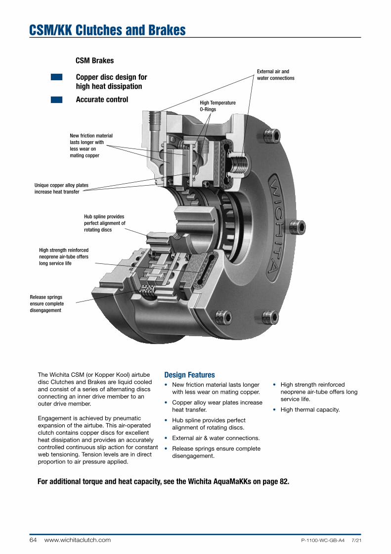
64 www.wichitaclutch.com P-1100-WC-GB-A4 7/21
CSM BrakesExternal air and water connections
Release springs ensure complete disengagement
High strength reinforced neoprene air-tube offers long service life
Hub spline provides perfect alignment of rotating discs
New friction material lasts longer with less wear on mating copper
Unique copper alloy plates increase heat transfer
The Wichita CSM (or Kopper Kool) airtube disc Clutches and Brakes are liquid cooled and consist of a series of alternating discs con nect ing an inner drive mem ber to an outer drive member. En gage ment is achieved by pneu mat ic ex pan sion of the airtube. This air-op er at ed clutch contains copper discs for excellent heat dissipation and provides an accurately con trolled continuous slip action for con stant web tensioning. Tension levels are in direct proportion to air pressure applied.
Copper disc design for high heat dissipation
Accurate control
Design Features• New friction material lasts longer
with less wear on mating copper.
• Copper alloy wear plates increase heat transfer.
• Hub spline provides perfect alignment of rotating discs.
• External air & water connections.
• Release springs ensure complete dis en gage ment.
• High strength reinforced neoprene air-tube offers long service life.
• High thermal capacity.
High Temperature O-Rings
For additional torque and heat capacity, see the Wichita AquaMaKKs on page 82.
CSM/KK Clutches and Brakes

12
4 56
78
69
10
11 1213
14
3
F
65P-1100-WC-GB-A4 7/21 www.wichitaclutch.com
8. Ring (Airtube End)
9. Floating Water Jacket As sem bly
10. Pressure Plate
11. Airtube
12. Segmented Shims
13. Airtube Holding Plate
14. Socket Head Capscrews
Component Parts 1. Socket Head Capscrews
2. Backplate Water Jacket Assembly
3. Release Springs
4. Ring (Backplate End)
5. Hub
6. Drive Plate As sem bly
7. Center Water Jacket As sem bly
Principle of Operation
Closed Cooling SystemAs shown here in the closed loop system, flexible water lines should be brought into each jacket at the 6 o’clock position. When the CSM Unit is used as a clutch, air vent tubes must be installed internally at the factory to insure proper filling of the water jackets. The CSM Clutches also require 0.35 BAR back pres sure on the outlet side of the triple passage roto-coupling to insure com plete evac u a tion of air from these jackets during rotation.
Referring to the closed loop cooling system, the equipment should be pro tect ed with low water pressure and high tem per a ture warn ing devices. For availability information, contact factory.
CSM Brakes
Water Cooled/High Heat Capacity
Liquid LevelControl
HoldingTank
Pump
EquipmentPowerSupply
HighTemperature
Warning
High PressureBy-Pass Valve(If Required)
FlexibleLines to Brake
Low PressureWarning
Outlet
Radiator
Inlet
Brake(4.13 BAR Max.)

66 www.wichitaclutch.com P-1100-WC-GB-A4 7/21
Typical ApplicationsDesign advantages• New friction material is longer lasting with
less wear on mating copper. Consistent torque response results directly with air pressure applied. Mechanically retained friction pads can be changed in field.
• Copper has a greater heat transfer capacity than most other metals.
• All factors affecting torque are fully con-trolled. Patented water flows through tangential cooling grooves to ensure effective mixing of cooling water for best heat con duc tiv i ty. Water volume of the jackets insures high water velocity, which reduces sedimentation and chemical for mation. Maximum inlet pressure is 4.13BAR/60 PSI.
• Close grain alloy iron jackets for coolant assure high resistance to corrosion.
• Releasing springs insure complete disengagement.
• By using a triple roto-coupling, the brake can be used as a constant slipping clutch.
• Composite pressure plate assures even distribution of pressure from actuator to braking surfaces, providing maximum contact area on friction surfaces.
• All coolant and air connections are external and easily accessible. Double outlets in center water jackets for multiple plate units 24” and larger.
• Air passages through brake greatly assist in keeping brake cool.
• Actuating member is a reinforced neoprene airtube which has low resistance to move ment, resulting in immediate reaction with small pres sure changes. Non-corrosion neoprene is unaffected by ac tu at ing medium.
Wichita CSM Brakes provide precise weight on bit control on drawworks for drilling rigs.
CSM Brakes dissipate high heat loads in steel uncoiler applications.
CSM brakes increase control on marine winches.
CSM/KK Clutches and Brakes

F
67P-1100-WC-GB-A4 7/21 www.wichitaclutch.com
CalculationsFor the calculations below, consult CSM Brake Specifications Chart on the next two pages.
The brake selected for this application is a CSM 218, with 5.5 inch bore.
Max. Tension = Max. N/mm x Max. Web Width = 2.63 x 3050 = 8022 N.
Max. Torque = Max. Tension x Max. Roll Dia (M). 2 = 8022 x 2.135/2 = 8563 Nm
Max. RPM = Max. Web Speed Min. Roll Dia. x π = 450 / (3.142 x .305 = 470 RPM
Heat HP = Max. Tension x Max. Web Speed/60,000 = 8022 x 450 = 60.2 kW 60,000
Min. Tension = Min. tension x Min. Web Width (mm) = 1.75 x 2135 = 3736 N.
Min. Torque = Min. Tension x Min. Roll Dia. 2 = 3736 x .305 = 570 Nm.
Min. RPM = Min. Web Speed Max. Roll Dia. x π = 225 / (3.142 x 2.135 = 34 RPM
How to select1. Select a brake with equal to or greater
thermal capacity. The CSM214 has 115 kW x 0.7 = 78.4 kW. The requirement is 60.2 kW.
2. Check torque capacity vs. required. The CSM214 has 4745 Nm @ 5.5 bar. The requirement is 8563 Nm. Therefore, a CSM214 Brake will not produce enough torque for this application. A CSM218 Brake would be the best choice.
3. Check maximum bore. The requirement is 5.00 inches. The CSM218 maximum bore is 5.5 inches
4. Check maximum RPM. The requirement is 470 RPM. The maximum RPM for the CSM218 is 1300 RPM.
Max. Air = Max. Torque x 7 BAR
Pressure Catalog Torque Rating Required
= 8563 x 7 = 5.64 BAR 10620
Min. Air = Min.Torque x 7 BAR
Pressure Catalog Torque Rating Required
= 570 x 7 = 0.38 BAR 10620
Selecting a CSM Brake for an unwind application
To properly select a tension brake for an unwind application the following in for ma tion is needed:
Max. Roll Diameter . . . . . . . . . . . . . 2135 mm. Max. Web Width . . . . . . . . . . . . . . . 3050 mm. Max. Web Speed . . . . . . . . . . . . . . . 450 M/min. Max. Tension . . . . . . . . . . . . . . . . . . 2.63 N/mm. Air Pressure Available . . . . . . . . . . . 7 BAR. Min. Roll Diameter . . . . . . . . . . . . . . 305 mm. Min. Web Width . . . . . . . . . . . . . . . . 2135 mm. Min. Web Speed . . . . . . . . . . . . . . . 225 mm/min Min. Tension . . . . . . . . . . . . . . . . . . 10 PLI
Water Cooled/High Heat Capacity

68 www.wichitaclutch.com P-1100-WC-GB-A4 7/21
CSM Brakes
Specifications
Heat Capacity Dynamic Torque Capacity* Series Parallel Max Bore ModelSize Nm Water Hosing Water Hosing Rect. Key ATD- 5.5 BAR 7 BAR HP/kW HP/kW mmCSM 106 151 192 10 / 7.5 15 / 11
44CSM 206 302 384 20 / 15 30 / 22 CSM 108 479 610 21 / 16 32 / 24 CSM 208 959 1220 42 / 31 64 / 48 57 CSM 308 1438 1830 63 / 47 96 / 72 CSM 111 1065 1356 35 / 26 53 / 40 CSM 211 2131 2712 70 / 52 105 / 78 76 CSM 311 3196 4067 105 / 78 158 / 118 CSM 114 1864 2373 50 / 37 75 / 56 CSM 214 3728 4745 100 / 75 150 / 112 111 CSM 314 5593 7118 150 / 112 225 / 168 CSM 116 2841 3615 65 / 48 98 / 73
121CSM 216 5681 7231 130 / 97 195 / 145 CSM 118 4172 5310 80 / 60 120 / 89 CSM 218 8344 10620 160 / 119 240 / 179 140 CSM 318 12517 15930 240 / 179 360 / 268 CSM 121 5504 7005 100 / 75 150 / 112 CSM 221 11008 14010 200 / 149 300 / 224 165 CSM 321 16511 21015 300 / 224 450 / 336 CSM 124H 11185 14236 190 / 142 285 / 213 CSM 224H 22370 28471 380 / 283 570 / 425 194CSM 324H 33556 42707 570 / 425 855 / 638CSM 127 13316 16947 175 / 130 263 / 196
203CSM 227 26631 33894 350 / 261 233 / 174CSM 130 17754 22596 230 / 172 345 / 257 CSM 230 35508 45193 460 / 343 690 / 515 229 CSM 330 53263 67789 690 / 515 1035 / 772 CSM 136H 36154 45193 500 / 373 750 / 559 CSM 236H 72308 90385 1000 / 746 1500 / 1119
229
CSM 336H 108462 135578 1500 / 1119 2250 / 1678 CSM 436H1 141227 180771 2000 / 1491 3000 / 2237 CSM 3462 233468 297142 2200 / 1641 3300 / 2461 317* Static torque will vary with temperature. Maximum air pressure is 100 PSI / 7 BAR. Minimum recommended air pressure is 3 PSI / 0.2 BAR. Note: Maximum water jacket inlet pressure is 60 PSI / 4.13 BAR. Brakes with as great as 50% higher torque capacity is available upon request. 1 Current design is with the Marine Corrosion package. A Non-Marine unit is available upon request. 2 Current design is for intermittent duty applications. Such as, anchor, mooring, take-up and traction type winch applications.
CSM/KK Clutches and Brakes

F
69P-1100-WC-GB-A4 7/21 www.wichitaclutch.com
Parallel Water Flow Model Max. % Ethylene Glycol Total Brake Hub & Drive PlateSize Speed LPM Wt. Wt. J=mr2
ATD- RPM 0% 30% 50% kg kg kgm 2
CSM 106 3,800
6 7.4 8.5 20.4 2.5 0.01
CSM 206 11 14.8 17 32.2 5.3 0.01
CSM 108 12 1.6 19 30.8 5.0 0.03
CSM 208 2,860 24 32 38 52.6 11.1 0.05
CSM 308 36 48 57 74.4 17.2 0.08
CSM 111 20 26 30 66.2 10.9 0.08
CSM 211 2,100 40 52 60 104.3 24.5 0.17
CSM 311 60 78 78 142.4 38.1 0.25
CSM 114 28 37 45 100.2 18 0.21
CSM 214 1,600 57 74 90 156.5 36 0.44
CSM 314 84 111 135 213.2 54 0.67
CSM 116 1,400
37 48 56 135 34 0.51
CSM 216 74 96 111 295 65 1.07
CSM 118 45 60 72 188 39.9 0.76
CSM 218 1,300 90 120 144 256 79.8 1.52
CSM 318 135 180 216 324 119.7 2.28
CSM 121 57 74 90 272 63 1.43
CSM 221 1,100 114 148 170 395 103 2.70
CSM 321 170 221 255 488 137 4.09
CSM 124H 106 144 170 424 109 4.64
CSM 224H 960 212 288 340 680 186 8.85
CSM 324H 318 432 510 937 263 13.07
CSM 127 850
102 133 153 445 103 3.87
CSM 227 204 266 307 599 193 7.55
CSM 130 132 170 204 514 119 5.86
CSM 230 760 264 340 408 839 240 11.59
CSM 330 396 510 612 1163 361 17.28
CSM 136H 284 369 454 1157 243 17.28
CSM 236H 640
568 738 908 1865 420 33.31
CSM 336H 852 1107 1362 2538 764 68.3
CSM 436H 1136 1476 1703 3072 997 87.6
CSM 346 480 1249 1624 1874 4899 1379 210
Pressure Drop Pressure Drop Parallel Flow w/ Series Flow w/ Maximum Model % Ethylene Glycol % Ethylene Glycol Lining Water Size PSI / BAR PSI / BAR Wear VolumeATD- 0% 30% 50% 0% 30% 50% cm dm 3 dm3 CSM 108 4 / 0.14 9 / 0.62 9 / 0.62 0.13CSM 208 0.9 / 0.06 1.6 / 0.11 2.3 / 0.16 11 / 0.76 25 / 1.72 32 / 2.21 1.0 0.2 0.26CSM 308 15 / 1.03 34 / 2.34 41 / 2.83 0.4CSM 114 4 / 0.14 8 / 0.55 12 / 0.83 0.33CSM 214 1.2 / 0.08 1.6 / 0.11 1.8 / 0.12 24 / 1.66 40 / 2.76 52 / 3.59 1.3 1.0 0.65CSM 314 28 / 1.93 48 / 3.31 — 1CSM 118 7 / 0.48 13 / 0.9 20 / 1.38 0.8CSM 218 1.7 / 0.12 2.4 / 0.17 2.8 / 0.19 52 / 3.59 — — 1.5 1.2 1.5CSM 318 — — — 2.35CSM 124H 7 / 0.48 11 / 0.76 14 / 0.97 1.8CSM 224H 1.9 / 0.13 2.4 / 0.17 3.1 / 0.21 23 / 1.59 35 / 2.41 48 / 3.31 2.0 3.3 3.6CSM 324H 30 / 2.07 46 / 3.17 — 1.8CSM 130 9 / 0.62 14 / 0.97 21 / 1.45 3.1CSM 230 2.1 / 0.14 2.4 / 0.17 3.1 / 0.21 31 / 2.14 48 / 3.31 — 2.0 3.9 6.2CSM 330 40 / 2.76 — — 9.3CSM 136H 14 / 0.97 24 / 1.66 — 4.7CSM 236H 4.0 / 0.28 5.3 / 0.37 7.2 / 0.50 60 / 4.14 — — 2.0 8.2 9.3CSM 336H — — — 14
CSM Brakes
Specifications (Continued)
Water Cooled/High Heat Capacity

70 www.wichitaclutch.com P-1100-WC-GB-A4 7/21
For mounting hole pattern, see following pages.
CSM Brake
CSM/KK Clutches and Brakes

F
71P-1100-WC-GB-A4 7/21 www.wichitaclutch.com
Dimensions: mm Model A B C(1) Size ATD- Pilot Hole Circle Pilot D F G H JCSM 106 50.8
19.1 133.4
3.3CSM 206 220 203.2 190 223.8 117.6 193.8
CSM 108
50.8 144.3
CSM 208 108 28.7 214.1 6.4
CSM 308 310 282.58 220 288.5
177.8 282.4
CSM 111
73.2 160.5
CSM 211 155.7 19.1 242.8 6.4
CSM 311 400 374.65 295 374.7
231.6 325.4
CSM 114
82.6 26.9 177.8
CSM 214 149.4 42.9 268.5 6.4
CSM 314 470 444.5 370 444.5
231.9 42.9 358.9
CSM 116 101.6 31.8
192.0 6.4
CSM 216 540 508 410 508 177.8 292.1
CSM 118
921.2 26.9 203.2
CSM 218 181.1 41.4 309.6 6.4
CSM 318 590 558.8 470 555.8
273.1 41.4 416.1
CSM 121
139.7 31.8 212.9
CSM 221 201.7 38.1 401.6 6.4
CSM 321 685 647.7 540 632
316 31.8 436.6
CSM 124H
127 248.7
CSM 224H 219.2 35.1 372.9 6.4
CSM 324H 760 730.25 620 787.4
346.2 496.8
Dimensions: mmModel L R U V(2) - InletsSize ATD- No. - Size M N Q No. - Size T Min. Max. No. - SizeCSM 106
4 x ø9
2 - 1/2 NPT 2 - 1/4 NPT
CSM 206 74.7 61.7 9.7 50.8 15.2 44.5 3 - 1/4 NPT
CSM 108
2 - 3/8 NPT
CSM 208 4 x ø14
2 - 1/2 NPT 3 - 3/8 NPT
CSM 308 111.3 88.9 35.1 95.3 25.4 57.2
4 - 3/8 NPT
CSM 111
2 - 1/2 NPT
CSM 211 4 x ø18
2 - 1/2 NPT 3 - 1/2 NPT
CSM 311 136.7 117.6 28.7 133.4 25.4 76.2
4 - 1/2 NPT
CSM 114
2 - 1/2 NPT
CSM 214 6 x ø18
2 - 1/2 NPT 3 - 1/2 NPT
CSM 314 187.5 165.1 38.1 177.8 35.1 111.3
4 - 1/2 NPT
CSM 116 10 x ø18
2 - 1/2 NPT
2 - 1/2 NPT
CSM 216 218.9 190.5 38.1 212.9 35.1 120.7 3 - 1/2 NPT
CSM 118
2 - 1/2 NPT
CSM 218 10 x ø18
3 - 1/2 NPT 3 - 1/2 NPT
CSM 318 238.3 209.6 38.1 247.7 50.8 139.7
4 - 1/2 NPT
CSM 121
2 - 3/4 NPT
CSM 221 10 x ø18
3 - 1/2 NPT 3 - 3/4 NPT
CSM 321 289.1 266.7 44.5 289.1 50.8 165.1
4 - 3/4 NPT
CSM 124H
2 - 1 NPT
CSM 224H 10 x ø18
3 - 1/2 NPT 4 - 1 NPT
CSM 324H 322.3 292.1 23.9 384.0 50.8 193.8
6 - 1 NPT(2) Number of inlets and outlets are equivalent.
(Consult factory for drawing before final layout.)
(1) Dimension "C" is given as a nominal figure. The applicable tolerance is ISO H7. (Consult factory for drawing before final layout.)
Water Cooled/High Heat Capacity

72 www.wichitaclutch.com P-1100-WC-GB-A4 7/21
For mounting hole pattern, see following pages.
CSM Brake
CSM/KK Clutches and Brakes

F
73P-1100-WC-GB-A4 7/21 www.wichitaclutch.com
Dimensions: mm Model A B C(1) Size ATD- Pilot Hole Circle Pilot D F G H J CSM 127
127 228.6
CSM 227 832 800.10 700 384.3 35.1 6.4
219.2 349.3
CSM 130
117.6 239.8
CSM 230
940 901.7 775 882.7 235 35.1 362 6.4
CSM 330
352.6 482.6
CSM 136H
143 28.7 320.8
CSM 236H
1105 1066.8 925 1130.3 279.4 36.3 89.2 6.4
CSM 336H (2)
422.4 36.3 654.3
CSM 436H (2)
1130 1079.5 925 1130.3 628.7 36.3 819.4 6.4
CSM 346 (2)
1492 1441.45 1220 1441.45 527.1 69.9 739.9 6.4
Dimensions: mmModel L R U V(3) - InletsSize ATD- No. - Size M N Q No. - Size T Min. Max. No. - SizeCSM 127
14 x ø18
3 - 1/2 NPT 2 - 3/4 NPT
CSM 227 358.9 317.5 44.5 358.9 63.5 203.2 3 - 3/4 NPT
CSM 130
2 - 1 NPT
CSM 230 16 x ø22
4 - 1/2 NPT 4 - 1 NPT
CSM 330 400.1 362 50.8 441.5 63.5 228.6
6 - 1 NPT
CSM 136H(2)
2 - 1.25 NPT
CSM 236H(2) 16 x ø22
4 - 1/2 NPT 4 - 1.25 NPT
CSM 336H(2) 419.1 355.6 30.2 441.5 152.4 228.6
6 - 1.25 NPT
CSM 436H(2) 16 x ø22
4 - 1/2 NPT
8 - 1.25 NPT
419.1 355.6 31.8 441.5 152.4 228.6
CSM 346(2) 22 x ø22
4 - 1/2 NPT
6 - 1.25 NPT 736.6 609.6 79.5 768.4 203.2 406.4(3) Number of inlets and outlets are equivalent. (Consult factory for drawing before final layout.)
(1) Dimension "C" is given as a nominal figure. The applicable tolerance is ISO H7. (Consult factory for drawing before final layout.)(2) For dimensions of the 36H, 46, and 48 models please consult factory for drawing before final layout.
Water Cooled/High Heat Capacity

74 www.wichitaclutch.com P-1100-WC-GB-A4 7/21
CSM Brakes - Mounting Hole Pattern
CSM Brakes
Sizes 19 & 25
CSM/KK Clutches and Brakes
Water Outlets
Water Outlets
Water Outlets
Water Inlets
CTYP.
CTYP.
ØBH.C.
ØBH.C.

F
75P-1100-WC-GB-A4 7/21 www.wichitaclutch.com
Dimensions: mm No. of No. of Holes, Model Mounting A B Hole Pattern CSM Holes Size Hole Circle is Based C D
6 4 8.6 203.20 4 45° 90°
8 4 13.5 282.58 6 60° 120°
11 4 16.7 374.65 6 60° 120°
14 6 16.7 444.50 8 45° 90°
16 10 16.7 508.00 12 30° 60°
18 10 16.7 558.80 12 30° 60°
19 12 17.5 558.80 12 30° —
21 10 16.7 647.70 12 30° 60°
24H 10 16.7 730.25 12 30° 60°
25 12 16.7 730.25 12 30° —
27 14 16.7 800.10 16 22.5° 45°
30 16 19.8 901.70 18 20° 40°
36H 16 20.6 1066.80 18 20° 40°
436H 16 26.9 1079.50 18 20° 40°
46 22 26.2 1441.45 24 15° 30°
Water Cooled/High Heat Capacity

76 www.wichitaclutch.com P-1100-WC-GB-A4 7/21
CSM Brakes - Spring-Set Brakes
CSM SS Brake
CSM SS-HYD Brake
See previous pages for dimensional information.
CSM/KK Clutches and Brakes
Width
Width

F
77P-1100-WC-GB-A4 7/21 www.wichitaclutch.com
Water Cooled/High Heat Capacity
Dimensions: mm Model Dynamic Torque Capacity* Size Release Pressure Width ATD- Nm BAR mm
CSM SSB 218 5434 6.2 381 CSM SSB 224H(3) 11840 5.2 446.8 CSM SSB-HYD 124H 9942 88.3 320.8 CSM SSB-HYD 224H 18077 88.3 445 CSM SSB 330H(1) 84612 6.9 576.3 CSM SSB 236H(2,4) 73370 8.3 559.6 CSM SSB 336H(1,2,4) 133070 6.9 726.4 CSM SSB 336H(2,4) 106270 8.3 726.4* Static torque will vary with temperature. Note: Maximum water jacket inlet pressure is 4.13 BAR. Brakes with as great as 50% higher torque capacity is available upon request. (1) Current design is with enhanced linings. A unit with regular linings is available upon request.(2) Current design is with the Marine Corrosion package. A Non-Marine unit is available upon request.(3) Current design is without hub. A unit with hub is available upon request. (4) Mounting same as 436H CSM except with 1079.5 mm hole circle. Feature Differences: The CSM SS brake uses air to release the brake, where as the CSM SS-HYD brake uses hydraulic pressure to release the brake.

78 www.wichitaclutch.com P-1100-WC-GB-A4 7/21
CSM Custom Units - CSM SS Clutch
See previous pages for dimensional information.
CSM/KK Clutches and Brakes
Water Ports
Air / HydaulicPort

F
79P-1100-WC-GB-A4 7/21 www.wichitaclutch.com
Dimensions: mm Dynamic Torque Model Capacity* with Heat Roto - Max. Speed Size Release Pressure Capacity Coupling R/C Unit WidthATD- Nm BAR HP(kW) NPT RPM RPM mm
CSM SSC 224(2)
1-1/4" 40 475
8389 5.2 260 (4) 838.2
CSM SSC 324(2)
1-1/4" 40 475
12507 5.2 300 (5) 954.5
CSM SSC 224H(1,2)
1-1/2" 250 475
17764 5.2 425 (6) 987.3
CSM SSC 324H(1,2)
1-1/4" 40 475
31488 6.6 300 (6) 991.4
CSM SSC 236H(2,3)
2" 250 300
61247 6.9 975 (5) 819.2
CSM SSC-HYD 236H(2,3)
2" 250 300
61247 100.0 975 (5) 819.2* Dynamic torque will vary with temperature. Note: Maximum water jacket inlet pressure is 4.13 BAR. Brakes with as great as 50% higher torque capacity is available upon request. (1) Current design is with enhanced linings. A unit with regular linings is available upon request.(2) Current design is with the Marine Corrosion package. A Non-Marine unit is available upon request.(3) Mounting same as 436H CSM except with 1079.5 mm hole circle. (4) Series hosing (5) Parallel hosing (6) Partial-parallel hosing Feature Differences: The CSM SS clutch uses air to release the clutch where as; the CSM SS-HYD clutch uses hydraulic pressure to release the clutch.
Water Cooled/High Heat Capacity

80 www.wichitaclutch.com P-1100-WC-GB-A4 7/21
3-Way Roto-Coupling (for water-cooled Clutches)
Dimensions: inches
Thread Size A B C D E F G
MODEL A 7.250 3/8"–18 NPT 1.00 6.50 3.000 .50 5/8"–18
MODEL B 11.000 1-1/4"–11-1/2 NPT 1.375 7.25 5.375 .687 1/4" NPT
MODEL C 18.875 2"–11-1/2 NPT 1.250 10.00 9.000 — 1"–14
CSM/KK Clutches and Brakes
Hose not Included
Cooling Water

F
81P-1100-WC-GB-A4 7/21 www.wichitaclutch.com
CSM Brake Air Hose Kits
Air hose kits contain all nec es sary parts (fittings, hoses and extensions) to com plete ly plumb the brake air system.
Optional Quick Release Valves can replace elbows on most units (see page 20 & 21).
Water Cooled/High Heat Capacity

82 www.wichitaclutch.com P-1100-WC-GB-A4 7/21
The newest addition to Wichita Clutch's family of water cooled airtube clutches and brakes
For increased torque and heat capacity, Wichita has
introduced the AquaMaKKs™ range clutches and
brakes, which are pneumatically or hydraulically
controlled and water cooled. They consist of a
series of alternating friction discs and water jackets.
Torque is transmitted by applying axial force from the
pneumatic, hydraulic, or spring set actuator. Copper
wear plates are used for superior heat dissipation.
AquaMaKKs provides accurate torque control for
constant tensioning and are perfectly suited for
applications in oil and gas, metal processing and
forming, forestry, and marine deck machinery. See
the following page for AquaMaKKs™ applications:
Design Benefits
• Simplicity of design with fewer parts simplifies
installation and maintenance, saving both time
and money.
• The standard AquaMaKKs design incorporates
premium materials and finishes suitable for
marine deck environments. No optional salt
water corrosion protection is required.
• Shim design makes it easy to maintain and
adjust for wear.
• Unique patent pending water jacket design
ensures high heat absorption and torque
stability, allowing for greater heat dissipation
over similar sized competitive units.
• Unique mounting pattern enables direct
replacement to Wichita or competitors’ units,
requiring no design changes for the customer.
• AquaMaKKs is a perfect solution for
field retrofits, rebuilds or new OEM
applications.
AquaMaKKs Clutches and Brakes

F
83P-1100-WC-GB-A4 7/21 www.wichitaclutch.com
Oil and Gas The AquaMaKKs family is ideally suited for superior water cooled tension control for drawworks applications. It also can be the perfect solution for integration into electronic drilling systems as well as traditional style drawworks control systems.
Features that make AquaMaKKs ideal for oil and gas applications:• Compatible with major electronic drilling systems
• Airtube design has less hysteresis than piston type actuators, making it ideal for automatic drilling systems
• Engineered packaged solutions including shafts, water kits, covers, and deck mounts
• The unit can be easily removed for service if required and/or quickly swapped out for maximum rig availability and rapid serviceability, reducing expensive downtime
Metal Processing & Metal Forming AquaMaKKs clutches and brakes can be used to control tension on coilers in metal processing plants and to control tension in unwind stands and slitters in metal forming facilities.
Features that make AquaMaKKs ideal for metal processing and metal forming applications:• Compatible with PLC
control systems
• Higher thermal capacity than comparable models
• Easy to maintain minimizing downtime
• Open design concept for easy wear inspection
• Safety covers provided for increased operator and plant safety
Marine Deck Machinery Positioning and Mooring Winches require high heat dissipation and accurate tension control. That's why AquaMaKKs is ideal for these applications.
Features that make AquaMaKKs ideal for marine deck applications:• The standard AquaMaKKs design incorporates premium materials and finishes suitable for marine deck environments.
• Compatible with electronic and analog control systems for tension winches
• Long lasting friction material for improved wear life
• Optional designs available for suitability in low temperature environments
• Accessories and packaged engineered solutions available such as deck mounts, manifold kits, water connection kits, covers, and sensor mounting provisions
Forestry AquaMaKKs water cooled brakes provide precise tension control on winch drives for mobile forestry equipment, such as yarders.
Features that make AquaMaKKs ideal for forestry applications:• Compatible with tension control
systems on yarders
• Open case design enables easy wear inspection and serviceability
• Higher thermal capacity than comparable models
• Lighter weight version available for mobile equipment
No optional salt water corrosion protection is required.
AquaMaKKs Water Cooled Clutches and Brakes
Air, hydraulic, or spring set actuated and water cooled design, featuring copper wear plates optimized for heavy-duty continuous slip tension applications
AquaMaKKs Clutches and Brakes

84 www.wichitaclutch.com P-1100-WC-GB-A4 7/21
Stainless Steel Drive
Pins
Stainless Steel
Springs
Marine quality finishes suitable for marine deck environments
Support Column
Copper Wear Plate
Bolted On Friction Disc
Patented Water Jacket Flow Design
Water Jacket
Reliable AirtubeSafety Cover
Features • Durable air tube design with high strength reinforced neoprene air-tubes, offering longer service life.
• Water channels for balanced water flow for the highest thermal capacity.
• Long-lasting friction material with minimal wear on mating copper.
• Copper alloy wear plates enable higher heat transfer than any other metals.
• Hub spline provides perfect alignment of rotating discs.
• External air & water connections.
• Release springs ensure complete disengagement.
• Adjustment for wear is easily accomplished by removing shims without any unit disassembly.
• Unique torque pin column arrangement provides structural integrity of case.
• Open case design with covers for safe, simple, visual inspection and easy maintenance.
• The standard AquaMaKKs design incorporates premium materials and finishes suitable for marine deck environments. No optional salt water corrosion protection is required.
Options • Standard and HICO friction materials available.
• Optional HICO friction material provides up to 50% higher torque.
• Provisions for electronic wear monitoring.
• Customer specific back-plate mounting configurations.
• Custom engineered solutions available for adding accessories such as deck mount assemblies, water kits, shaft assemblies, etc.
• Materials available for operation in low temperature environments.
• Hydraulic piston actuation available.
• Spring Set version with either air or hydraulic release available.
AquaMaKKs Clutches and Brakes

7 – 2 1 9 A M – B – 1 X X X
B
A
85P-1100-WC-GB-A4 7/21 www.wichitaclutch.com
inches mm
Model Size Assembly (A) Diameter (B) Width
ATD- Number in. (mm) in. mm
KKB119AM 7-119AM-B-1000 28.28 718 12.35 317
KKB219AM 7-219AM-B-1000 28.28 718 18.00 457
KKB319AM 7-319AM-B-1000 28.28 718 23.65 601
KKB225AM 7-225AM-B-1000 34.12 867 20.16 512
KKB325AM 7-325AM-B-1000 34.12 867 26.85 682
KKB136AM 7-136AM-B-1000 45.50 1155 11.70 297
KKB236AM 7-236AM-B-1000 45.50 1155 18.80 478
KKB336AM 7-336AM-B-1000 45.50 1155 25.90 658
KKB436AM 7-436AM-B-1000 45.50 1155 33.06 840
Dynamic Torque Capacity with Standard Linings Heat Capacity
(optional linings available) Series Parallel Max Bore Model Size Assembly lb.in. Nm Water Hosing Water Hosing Rect. Key
ATD- Number 80 PSI 100 PSI 5.5 BAR 7 BAR HP/kW HP/kW in/mm
KKB119AM 7-119AM-B-1000 66,500 83,100 7,500 9,380 93/69 185/138 5.50/140KKB219AM 7-219AM-B-1000 133,000 166,300 15,000 18,700 185/135 370/276 5.50/140
KKB319AM 7-319AM-B-1000 199,500 249,000 22,500 28,100 278/207 555/414 5.50/140
KKB225AM 7-225AM-B-1000 264,000 330,000 29,800 37,200 350/261 700/522 8.13/207
KKB325AM 7-325AM-B-1000 396,000 495,000 44,700 55,900 600/447 1200/895 8.13/207
KKB136AM 7-136AM-B-1000 322,000 402,000 36,300 45,400 425/317 850/633 8.13/207
KKB236AM 7-236AM-B-1000 644,000 805,000 72,700 90,900 875/652 1750/1304 9.00/229
KKB336AM 7-336AM-B-1000 966,000 1,208,000 109,100 136,400 1275/950 2550/1900 9.00/229
KKB436AM 7-436AM-B-1000 1,288,000 1,611,000 145,600 182,000 1700/1260 3400/2535 9.00/229
Dimensions
Specifications
1 – 4
Qty. of Drive Plates1 = Air Set Water Cooled2 = Spring Set Water Cooled3 = Low Inertia4 = Low Inertia Spring Set5 = Reserved
6 = Clutch7 = Brake
Clutch or Brake
19, 25 or 36
Unit Size
W or B
Internal Code Factory-Provided Sequential Number
Model øA øB øC Hole Circle PLT THK
in. mm in. mm in. mm in. mm in. mm
19 28.28 718 11.00 279 .656 17 25.50 648 1.38 35
25 34.12 867 16.70 424 .656 17 31.00 787 1.38 35
36 45.50 1156 16.75 425 1.06 27 42.72 1085 1.38 35
Mounting Hole Pattern
Order Numbering System
Dimensions and Specifications
AquaMaKKs Clutches and Brakes

Separator springs located on pins between water jackets over drive plates
Stainless Steel Drive pin(4 each)
Anti-rotation pin
Support column(4 each)
Top/Bottomcovers
Shim stacks
Backplate
Backwater jacket
Side covers
Support columnmounting bolt
Drive plate assembly
Friction material disk(both sides)
Button head cap screws
Water jacket pairlocates between drive plates
Sintered bronze bushing
Copper wear plate
Water jacket assembly
Pressure plate
Air tube assembly
Air tube holding plate
Air tube holding plate mounting bolt
Drive pin securing nut
86 www.wichitaclutch.com P-1100-WC-GB-A4 7/21
Exploded View
AquaMaKKs Clutches and Brakes
Shim stacks
Backwater jacket
Backplate
Side covers
Support columnmounting bolt
Top/Bottomcover Support column
(4 each)
Anti-rotation pin
Stainless Steel Drive pin(4 each)
Separator springs locatedon pins between water jackets over drive plates
Drive plate assemblyFriction material disk(both sides)
Button headcap screws
Copper wear plate
Sintered bronze bushing
Water jacket assembly
Pressure plate
Air tube assembly
Air tube holding plate
Air tube holdingplate mounting bolt
Drive pinsecuring nut
Water jacket pairlocates betweendrive plates

87P-1100-WC-GB-A4 7/21 www.wichitaclutch.com
For assistance, please call, +44 (0) 1234 350 311
For after hours emergency service, call +44 (0) 1234 324 324
Custom Engineered Solutions with Wichita
With Wichita Clutch, you get more than just a
water cooled brake, you can get a turnkey solution.
Whether you need a brake painted a preferred color,
water connection kits, covers, shaft assemblies,
or deck mount assemblies, Wichita will provide a
custom engineered solution to meet your specific
needs. Call Wichita today for more information.
Custom Solutions

88 www.wichitaclutch.com P-1100-WC-GB-A4 7/21
Notes

OTHER PRODUCT SOLUTIONS FROM ALTRA MOTIONOur comprehensive product offerings include various types of clutches and brakes, overrunning clutches, engineered bearing assemblies, gearing and gear motors along with linear motion products, belted drives, couplings, limit switches, precision motors, drives & controls, miniature motors and engine braking systems.With thousands of product solutions available, Altra provides true single source convenience while meeting specific customer requirements. Many major OEMs and end users prefer Altra products as their No. 1 choice for performance and reliability.
WWW.ALTRAMOTION.COM
Premier Industrial Company Leading Brands
Engine Braking SystemsJacobs Vehicle Systems
Linear SystemsThomson
Specialty ComponentsKilianStromagTB Wood’s
Miniature MotorsPortescap
Precision Motors& AutomationKollmorgen
Electric Clutches & BrakesInertia DynamicsMatrixStromagWarner Electric
Heavy Duty Clutches & BrakesIndustrial ClutchStromagSvendborg BrakesTwiflexWichita Clutch
Overrunning ClutchesFormsprag ClutchMarland ClutchStieber
Engineered Couplings & Universal JointsAmeridrivesBibby TurboflexGuardian CouplingsHucoLamiflex Couplings StromagTB Wood’s
Gear Drives & Gear MotorsBauer Gear MotorBoston Gear Delroyd Worm GearNuttall Gear

Altra Industrial Motion
www.wichitaclutch.com
Altra Industrial Motion
P-1100-WC-GB-A4 7/21
The Brands of Altra Motion
Couplings
Ameridriveswww.ameridrives.com
Bibby Turbo� ex www.bibbyturbo� ex.com
Guardian Couplingswww.guardiancouplings.com
Hucowww.huco.com
Lami� ex Couplingswww.lami� excouplings.com
Stromag www.stromag.com
TB Wood’swww.tbwoods.com
Linear Systems
Thomsonwww.thomsonlinear.com
Geared Cam Limit Switches
Stromagwww.stromag.com
Engineered Bearing Assemblies
Kilianwww.kilianbearings.com
Electric Clutches & Brakes
Matrixwww.matrix-international.com
Stromagwww.stromag.com
Warner Electricwww.warnerelectric.com
Belted DrivesTB Wood’s www.tbwoods.com
Heavy Duty Clutches & Brakes
Twi� exwww.twi� ex.com
Stromagwww.stromag.com
Svendborg Brakeswww.svendborg-brakes.com
Wichita Clutchwww.wichitaclutch.com
Gearing & Specialty Components
Bauer Gear Motorwww.bauergears.com
Boston Gearwww.bostongear.com
Delevanwww.delevan.com
Delroyd Worm Gearwww.delroyd.com
Nuttall Gearwww.nuttallgear.com
Engine Braking Systems
Jacobs Vehicle Systemswww.jacobsvehiclesystems.com
Precision Motors & Automation
Kollmorgenwww.kollmorgen.com
Miniature Motors
Portescapwww.portescap.com
Overrunning Clutches
Formsprag Clutchwww.formsprag.com
Marland Clutchwww.marland.com
Stieberwww.stieberclutch.com
Wichita Clutch Facilities
North America
USA2800 Fisher RoadWichita Falls, TX 76302 - USA940-723-3400
Pneumatic Clutchesand Brakes
Europe
United KingdomAmpthill RoadBedford MK42 9RD - England+44 (0) 1234 350311
Pneumatic Clutchesand Brakes
Asia Pacifi c
Australia +61 2 9894 0133
China+86 21 5169-9255
Hong Kong +852 2615 9313
Singapore +65 6487 4464
Taiwan +886 2 2577 8156
Thailand +66 2322 5527
Neither the accuracy nor completeness of the information contained in this publication is guaranteed by the company and may be subject to change in its sole discretion. The operating and performance characteristics of these products may vary depending on the application, installation, operating conditions and environmental factors. The company’s terms and conditions of sale can be viewed at http://www.altramotion.com/terms-and-conditions/sales-terms-and-conditions. These terms and conditions apply to any person who may buy, acquire or use a product referred to herein, including any person who buys from a licensed distributor of these branded products.
©2021 by Wichita Clutch LLC. All rights reserved. All trademarks in this publication are the sole and exclusive property of Wichita Clutch LLC or one of its af� liated companies.