Embed Size (px)
Citation preview

Clutches, Brakes, Coupling, and Flywheels
� Clutches, brakes, couplings, and flywheels are a group of elementsusually associated with rotation that have in common the functionof storing and/or transferring rotating energy
� In analyzing the performance of these devices we shall beinterested in:
�The actuating force �The torque transmitted �The energy loss �The temperature rise

� Two inertias, I1 and I2, traveling at the respective angularvelocities; ω1and ω2, one of which may be zero in the case ofbrakes, are to be brought to the same speed by engaging the clutchor brake. Slippage occurs because the two elements are running atdifferent speeds and energy is dissipated during actuation, resultingin a temperature rise.
A simplified dynamic representation of a friction clutch or brake is shown in Fig. 16-la

� The varies types of devices to be studied may be classified asfollowing:
�Rim types with internal expanding shoes � Rim types with external contracting shoes �Band types � Disk or axial types� Cone types �Miscellaneous types
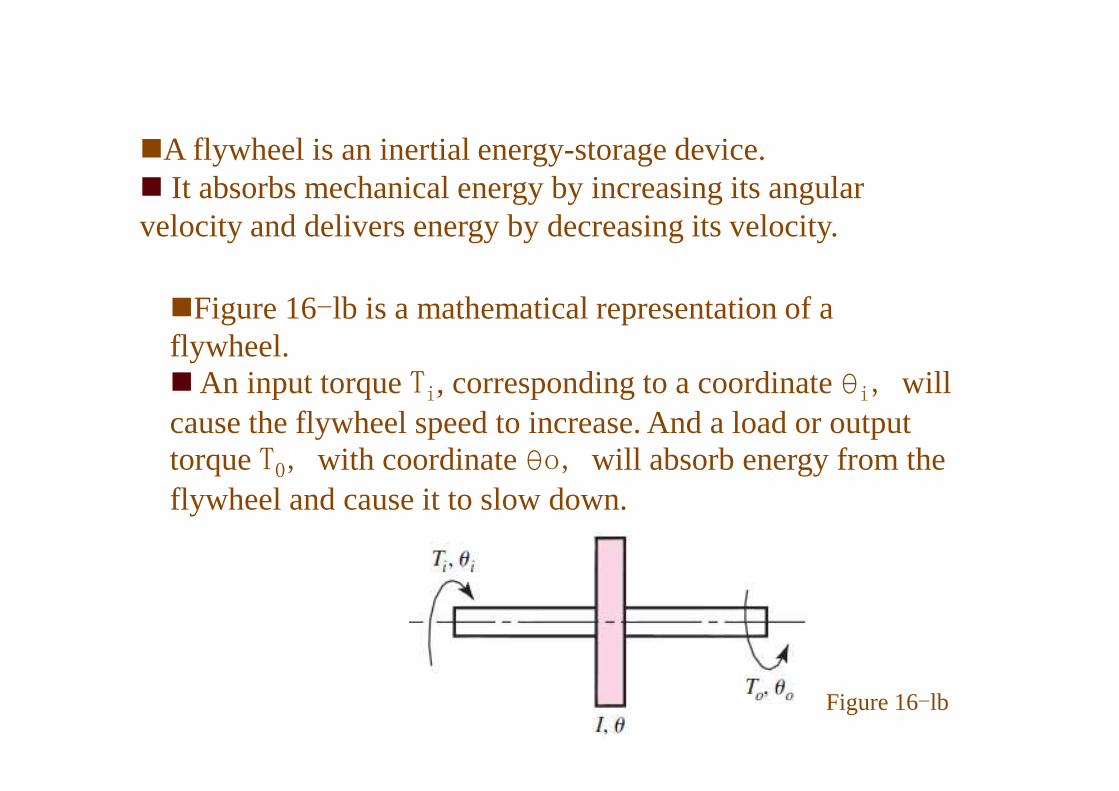
�Figure 16-lb is a mathematical representation of a flywheel.�An input torque Ti, corresponding to a coordinate θi, will
�A flywheel is an inertial energy-storage device. � It absorbs mechanical energy by increasing its angular velocity and delivers energy by decreasing its velocity.
�An input torque Ti, corresponding to a coordinate θi, will cause the flywheel speed to increase. And a load or output torque T0, with coordinate θo, will absorb energy from the flywheel and cause it to slow down.
Figure 16-lb

Static Analysis of Clutches and Brakes
• • Estimate, model, or measure the
pressure distribution on the friction
surfaces.
• Find a relationship between the
largest pressure and the pressure at
any point.
• Use the conditions of static
equilibrium to find the braking force or
torque and the support reactions.
Analyzing general procedure:
torque and the support reactions.
The net force in the y direction:
moment about C from the pressure:

sum of moment about the pin located at A:
sum of forces in the x-direction :
sum of forces in the y-direction :
Can F be equal to or less than zero?

4.2 Internal Expanding Rim Clutches and Brakes
� The internal-shoe rim clutch as
�often used in textile machinery, excavators, and machine tools
where the clutch may be located within the driving pulley.
� Expanding ring clutches benefit from centrifugal effects; transmit
high torque, even at low speeds; and require both positive
engagement and ample release force.
shown in Fig. 16-3 consists essentially of three elements:
�The mating frictional surface.�The means of transmitting the torque
to and fromthe surfaces.�The actuating mechanism.
Fig. 16-3

� To analyze an internal-shoe device, figure 16-4 shows a shoe pivoted at point A, with the actuating force acting at the other end of the shoe.
� Since the shoe is long, we cannot make the assumption that the distribution of normal forces is distribution of normal forces is uniform.
� The mechanical arrangementpermits no pressure to be appliedat the heel, thus we will assumethe pressure at this point to bezero.
Figure 16-4: internal friction shoe geometry

�It is the usual practice to omit the friction material for a shortdistance away frompoint A. This eliminates interference, and thematerial would contribute little to the performance anyway, as willbe shown.�Let us consider the pressurep acting upon an element of area of
the frictional material located at an angleθ from the hinge pin(Figure 16-4).�We designate the maximumpressurepa located at an angleθa from
from thehingepin.from thehingepin.

To find the pressure distribution on the periphery of the internal shoe,
consider point B
Deformation perpendicular to AB = hΔɸ.
From the isosceles Δ AOB, h = 2 r sin(ө/2)
h Δɸ = 2 rΔɸsin(ө/2) = rΔɸsin(ө)
The The deformation, and consequently the pressure, is proportional to sin θ.deformation, and consequently the pressure, is proportional to sin θ.
• If the shoe is short, pa occurring at the
end of the shoe, θ2.
• If the shoe is long, pa occurs at θa = 90◦
NB

�This pressure distribution has interesting and useful characteristics:
�The pressure distribution is sinusoidal with respect to the angle θ. �If the shoe is short, as shown in
Fig. 16-6a, the largest pressure on is occurring at the end of the shoe is pa occurring at the end of
the shoe, θ2. �If the shoe is long, as shown in
Fig. 16-6b, the largest pressure on the shoe is pa occurring at θa = 900
Figure 16-6: Defining the angleθa atwhich the maximum pressurepa occurswhen
(a)shoe exists in zoneθ1 ≤ θ2 ≤ π/2(b)(b) shoe exists in zoneθ1 ≤ π/2 ≤ θ2

�When θ=0, Eq. (16-1) shows that the pressure is zero. �The frictional material located at the heel therefore contributes very little to the braking action and might as well be omitted. �A good design would concentrate as much frictional material as possible in the neighborhood of the point of maximum pressure.maximum pressure.� In this figure the frictional material begins at an angle θ1, measured from the hinge pin A, and ends at an angle θ2. Any arrangement such as this will give a good distribution of the frictional material. � The actuating force F has components Fx and Fy and operates at distance c from the hinge pin.
Figure 16-7: Forces on the shoe

normal force
,
The moment Mf of these frictional forces:
The moment MN of normal force:
The actuating force FThe actuating force F
MN = Mf self-locking
MN > Mfthe dimension a must be such that
The torque T:
summation of the horizontal
and vertical forces:

� The following assumptions are implied by the preceding analysis:
�The pressure at any point on the shoe is assumed to beproportional to the distance fromthe hinge pin, beingzero at the heel.�This should be considered fromthe standpoint thatpressures specified by manufacturers are averages ratherthan maxima.�Theeffectof centrifugalforcehasbeenneglected.�Theeffectof centrifugalforcehasbeenneglected.�In the case of brakes, the shoes are not rotating, and nocentrifugal force exists.� In clutch design, the effect of this force must beconsidered in writing the equations of static equilibrium

� The shoe is assumed to be rigid. Since thiscannot be true, some deflection will occur,depending upon the load, pressure, and stiffnessof the shoe.� The resulting pressure distribution may be
differentfrom thatwhichhasbeenassumed.differentfrom thatwhichhasbeenassumed.� The entire analysis has been based upon a
coefficient of friction that does not vary withpressure.� Actually, the coefficient may varywith a
number of conditions, includingtemperature,wear, and environment.

External Contracting Rim Clutches and Brakes
� The moments of the frictional and normal forces about the hinge pin are the same as for the internal expanding shoes.
� Note:� when external contracting designs are used as clutches, theeffect of centrifugal
force is to decrease the normal force.� Thus, as the speed increases, a larger value of the actuatingforceF is required.

ΔTo get a pressure-distribution relation, we note that lining wear is such as to retain the
cylindrical shape
Δ This means the abscissa component of wear is w0 for all positions θ.
If wear in the radial direction
is expressed as w(θ),
w(θ) = w0 cos θ = KPVt
Symmetrically Located Pivot
K = a material constant
P = pressure
V = rim velocity, and
t = time
p(ө) = (constant) cosө= pa cosө
As, w0/(KVt) = constant
dN = pbrdө = pa brcos(ө)dөNormal force
The distance a to the pivot is chosen by finding where
the moment of the frictional forces Mf is zero.
Substituting dN

because of symmetry
Rx = −N and
Ry = − f N
T = afN
because of symmetry

Band-Type Clutches and Brakes
Because of friction and the rotation of the drum, the actuating force P2 is less than
the pin reaction P1
Summation of force in x-direction:
as sin(dө/2) = dө/2
Summation of force in y-direction:
Torque
Normal force
as dN = pdө

Machine systems can operate with intermittent motion. Starting and stopping operations can cycle frequently.
Motion control elements permit machine systems to achieve intermittent motion.
Motion Control elements:
• Clutches: Devices used to transmit power on an intermittent basis by connecting and/or disconnecting a driven component to and/or from the prime mover.
– Motor operates efficiently at continuous speeds.
– Avoids accelerating and/or de-accelerating the rotor of the motor each time a driven component of a machine needs to be cycled.
• Brakes: Device that absorbs the kinetic energy of a system and thus controls the • Brakes: Device that absorbs the kinetic energy of a system and thus controls the motion of the system by slowing down the system and/or bringing the system to rest.
Functions of a clutch:
• Connect a rapidly turning shaft to one that is initially stationary.
• Cause two shafts to turn at the same speed and to do so in a manner that shock is not produced.
• Limit torque that is transmitted or to prevent torque from being transmitted in a reverse direction.

16.5 Frictional-Contact Axial Clutches
�An axial clutch is one in which the mating frictional members aremoved in a direction parallel to the shaft.� One of the earliest of these is the cone clutch, which is simple in
construction and quite powerful.
�Advantages of the disk clutch include
�the more effective heat-dissipationsurfaces,� the favorable pressure distribution.� the large frictional area that can beinstalled in a small space,� the freedomfrom centrifugal effects,

� Let us now determine the capacity of such a clutch or brake in terms of thematerial and geometry.� Figure 16-16 shows a friction disk having an outside diameter D and an inside
diameterd.� We are interested in obtaining the axial forceF necessary to produce a certain
torqueT and pressurep.
�Two methods of solving the problem, depending upon the construction of the clutch, are in general use.� If the disks are rigid, then the greatest amount of wear will at first occur in the outer areas, since
Figure 16-16 a friction disk
of wear will at first occur in the outer areas, since the work of friction is greater in those areas.�After a certain amount of wear has taken place, the pressure distribution will change so as to permit the wear to be uniform. This is the basis of the first method of solution. �Another method of construction employs springs to obtain a uniform pressure over the area. It is this assumption of uniform pressure that is used in the second method of solution.

�After initial wear has taken place and the disks have worn down to a point where uniform wear is established, the axial wear can be expressed by :
Uniform Wear
By definition uniform wear is constant from place to place; therefore,
the total normal force
The torque is found by integrating the product of the frictional force and the radius:
substituting the value of F

Uniform Pressure
�When uniform pressure can be assumed over the area of the disk, the actuating
force F is simply the product of the pressure and the area. This gives:
�The torque is found by integrating the product of the frictional force and the radius:
substituting the value of F and noting p = pa

Disk Brakes
� There is no fundamental difference between a disk clutch anda disk brake.� The analysis of the preceding section applies to disk brakestoo.�We have seen that rim or drum brakes can be designed for self-energization�While this feature is important in reducing the braking effort required, it also has a
disadvantage.� Depicted in Fig. 16-19 is the geometry of an annular-pad brake contact area.
The governing axial wear equation is
wwww = ffff1ffff2KPVt KPVt KPVt KPVt
Figure 16–19 Geometry of contact area of
an annular-pad segment of a caliper brake.
wwww = ffff1ffff2KPVt KPVt KPVt KPVt
= The coordinate locates the line of
action of force F that intersects the y axis.
re = which is the radius of an equivalent
shoe of infinitesimal radial thickness.
p = the local contact pressure,
the friction torque T
the actuating force

�The equivalent radius re can be found from fFre = T
�The locating coordinate r bar of the activating force is found by taking moments
about the x axis:
Uniform Wear
� It is clear that for the axial wear to be the same everywhere, the productPV must be aconstant. The pressurep can be expressed in terms of the largest allowable pressurepa (which occurs at the inner radiusri) as :p = pari/r
and

In this situation, approximated by a new brake, p = pa
Uniform Pressure

16-7 Cone Clutches and Brakes
� It consists of acup keyed or splined to oneof the shafts, a cone that must slide axially onsplines or keys on the mating shaft, anda helicalspring to hold the clutch in engagement.� The clutch is disengaged by means of a fork
that fits into the shifting groove on the frictioncone.� The cone angleα and the diameterandface
width of the cone are the important geometricwidth of the cone are the important geometricdesign parameters.
Fig16–21 Cross section of a cone clutch
� If the cone angle (α) is too small, say, less thanabout 8°, then the force required to disengage theclutch may be quite large.� And the wedging effect lessens rapidly when
larger cone angles are used.� Depending upon the characteristics of the
friction materials, a good compromise canusually be found using cone angles between 10and 15°.

� To find a relation between the operating forceF and the torquetransmitted, designate the dimensions of the friction cone as shownin Figure 16- 22.� As in the case of the axial clutch, we can obtain one set of
relations for a uniform- wear and another set for a uniform-pressure assumption
element of area dA = (2πrdr)/sin α
radius = r
width = dr/sin α.

The pressure relation is the same as for the axial clutch:
Uniform Wear
The operating force will be the integral of the axial component of the differential force p d A.
The differential friction force is fpdA, and the torque is the integral
of the product of this force with the radius.of the product of this force with the radius.

Uniform Pressure
Substituting F

Energy Considerations
�When the rotating members of a machine are caused to stop by means of abrake, the kinetic energy of rotation must be absorbed by thebrake.�This energy appears in the brake in the form of heat. �In the same way, when the members of a machine that are initially at rest
are brought up to speed, slipping must occur in the clutch until the drivenmembers have the same speed as the driver.Kinetic energy is absorbedduring slippage of either a clutch or a brake, and this energy appearsas heat.� We haveseenhow the torque capacity of a clutch or brake depends� We haveseenhow the torque capacity of a clutch or brake dependsuponthe coefficient of friction of the material and upon a safe normalpressure.� However, the character of the load may be such that,if this torque value
is permitted, the clutch or brake may be destroyed by its owngenerated heat.� The capacity of a clutch is therefore limited by two factors,the
characteristics of the material and the ability of the clutch to dissipateheat.

� To get a clear picture of what happens during a simple clutching orbraking operation, refer to Fig. 16-la, which is a mathematical model of atwo-inertia system connected by a clutch.
�During the clutch operation both angularvelocities change and eventually becomeequal.� We assumethat the two shaftsare rigid and
� As shown, inertias I1and I2 have initial angular velocities of ω1 and ω2, respectively.
Figure 16–1
(a) Dynamic representation of a clutch or brake;
(b) Mathematical representation of a flywheel.
� We assumethat the two shaftsare rigid andthat the clutch torque is constant.
Writing the equation of motion for inertia 1 and 2
and
the instantaneous angular velocities ˙ θ1 and ˙ θ2

The difference in the velocities, sometimes called the relative velocity,
If the time required for the entire operation be t1
the time required for the engagement operation is
directly proportional to the velocity difference and
inversely proportional to the torque
the rate of energy-dissipation during the clutching operation to be
This shows that the energy-dissipation rate is greatest at the start, when t = 0.
inversely proportional to the torque
The total energy dissipated during the clutching operation or braking cycle is
Or in US customary units

�A brake or friction clutch should have the following lining material characteristics to a degree that is dependent on the severity of service:
�High and reproducible coefficient of friction�Imperviousness to environmental conditions, such as moisture�The ability to withstand high temperatures, together with goodthermal conductivity and diffusivity, as well as high specific heatcapacity
16-10 Friction Materials
capacity�Good resiliency� High resistance to wear, scoring, and galling�Compatible with the environment� Flexibility


Temperature Rise
The temperature rise of the clutch or brake assembly can be approximated by the
classic expression
or

If an object is at initial temperature T1 in an environment of
temperature T∞, then Newton’s cooling model is expressed as

For repetitive brake applications,
subsequent temperature peaks and and and and
valleys valleys valleys valleys are recordedare recordedare recordedare recorded
then the rate of heat transfer is
described by another Newtonian
equation:


Example 1:Example 1:Example 1:Example 1:The maximum band interface pressure on the brake shown in the
figure is 90 psi. Use a 14-indiameter drum, a band width of 4 in, a
coefficient of friction of 0.28, and an angle-of-wrap of 270◦. Find the band
tensions and the torque capacity.
Given: D = 300 mm, f = 0.28, b = 80
mm, ø = 270°, P1 = 7600 N.
SolutionSolutionSolutionSolution

ExampleExampleExampleExample2222:::: A brake has a normal braking torque of 320 N · m and heat-dissipating
surfaces whose mass is 18 kg. Suppose a load is brought to rest in 8.3 s from an
initial angular speed of 1800 rev/min using the normal braking torque; estimate the
temperature rise of the heat-dissipating surfaces.
Given: T = 320N.m, m = 18kg, t = 8.3second , ω1 = 180rev/min
SolutionSolutionSolutionSolution ω1 = 2πn/60 = 2π(1800)/60 = 188.5 rad/s and and and and ω2 = 0
the time required for engagement operation:time required for engagement operation:time required for engagement operation:time required for engagement operation:
The total energy dissipated during the clutching operation or braking cycle is