Embed Size (px)
Citation preview

SmartSiren® Platinum Installation and
Maintenance Instructions
25500151A0 10 14Printed in U.S.A.
Model SSP2000B
Model SSP3000B

blank page

SmartSiren Platinum Convergence Network 3
ContentsChapter 1 Safety Messages for Installers and Operators ......................................................7
Safety Messages to Installers of Sound/Light Systems ............................................................................7Safety Messages to Operators of Sound/Light Systems ...........................................................................9
Chapter 2 An Overview of the SmartSiren Platinum ............................................................11Siren, PA, and Speakers ..........................................................................................................................11Lightbars and SignalMasterTM Control ...................................................................................................11Programmable Solid-State Auxiliary Relays ..........................................................................................11Programmable Input Circuits ..................................................................................................................12LED Indicators and Visual Diagnostics (Model SSP3000B Only) ........................................................12System Specifications .............................................................................................................................12Siren Specifications ................................................................................................................................13SignalMaster Specifications (Model SSP3000B only) ...........................................................................13Relay Specifications ................................................................................................................................13SmartSiren Platinum Kit Contents ..........................................................................................................14
Chapter 3 Wiring the SmartSiren Platinum ...........................................................................16Selecting Mounting Locations ................................................................................................................16Convergence Network Connections .......................................................................................................18
Convergence Network Connections ..................................................................................................19Connections for 10 A Auxiliary Relays .............................................................................................20Connections for Low Current Auxiliary Relays ................................................................................22Connections for the Latitude SignalMaster .......................................................................................23Connections for Rear External Discrete SignalMaster (SSP3000B Only) .......................................23Connections for Relay Inputs 1 to 4 ..................................................................................................24Connections for the Ambient Light Sensor .......................................................................................25Park Disable (Cable Assembly P/N 1751542-01 or 1752542-NY) ..................................................26Speaker Connections (Cable Assembly P/N 17500307) ...................................................................27Horn Ring Transfer (Cable Assembly P/N 17500307) .....................................................................28Radio Rebroadcast (Cable Assembly P/N 17500307) ......................................................................30
Connecting the Control Pad ...................................................................................................................31Connecting the Active-Low Input Circuits .......................................................................................31Connecting Power to the Control Pad (without Ignition Timer) .......................................................32Connecting Power to the Control Pad (with Ignition Timer) ............................................................32Connecting the Federal Signal Microphone (P/N 258B8577-03) .....................................................33
Connecting the Siren to the Battery ........................................................................................................34Preparing to Connect the Power Leads .............................................................................................34

Contents
SmartSiren Platinum Convergence Network4
Connecting the Power Leads to the Vehicle Battery .........................................................................35
Chapter 4 Setting the Gain for Radio Rebroadcast and PA .................................................36Setting the Gain for Radio Rebroadcast .................................................................................................36Setting the Gain for Public Address (Microphone Volume) ...................................................................37
Chapter 5 Mounting the Siren and Control Pad ....................................................................38Mounting the Siren Amplifier/Relay Module .........................................................................................38Mounting the Control Pad ......................................................................................................................39
Chapter 6 Setting Control Pad Options .................................................................................41Entering Program Mode .........................................................................................................................41Turning Off or On the 10-Second Notification Beep ..............................................................................41Selecting Active-High Activation of Horn-Ring Transfer ......................................................................42Selecting Active-High Activation of Park Disable .................................................................................42Dimming or Turning Off the Button LEDs ............................................................................................43Resetting to the Factory Default Configuration ......................................................................................43Exiting Program Mode ...........................................................................................................................43
Chapter 7 Testing the Convergence Network Installation ...................................................44
Chapter 8 Control Pad Legends and Safety Messages ........................................................50Applying the Replaceable Control Pad Legends ....................................................................................50Distributing the Safety Message Card ....................................................................................................51Applying the Siren Safety Labels in the Vehicle ....................................................................................51
Chapter 9 Safety Messages to Personnel Servicing Federal Signal Electronic Sirens ...... 52
Chapter 10 Servicing the Convergence Network System ....................................................53Replacing the Slide Switch .....................................................................................................................53
Dismounting and Disconnecting the Control Pad .............................................................................53Replacing the Slide Switch in the Control Pad .................................................................................55Reinstalling the Control Pad .............................................................................................................56
Servicing the Siren Amplifier/Relay Module .........................................................................................56Uninstalling the Siren Amplifier/Relay Module ...............................................................................56Replacing an External Fuse ...............................................................................................................57Replacing a Terminal Insulator .........................................................................................................58Reinstalling the Siren Amplifier/Relay Module ................................................................................58
Getting Technical Support and Service ..................................................................................................59Ordering Replacement Parts ...................................................................................................................59Returning a Product to Federal Signal ....................................................................................................60

Contents
SmartSiren Platinum Convergence Network 5
Figures
Figure 3.1 Dimensions of the control pad ..................................................................................................17
Figure 3.2 Dimensions of the siren amplifier/relay module .......................................................................17
Figure 3.3 Serial port locations ..................................................................................................................19
Figure 3.4 Configurable activation options for 10 A relays with active-low capability ............................21
Figure 3.5 Connection for 10 A solid-state relays ......................................................................................21
Figure 3.6 Connection for 2 A solid-state relays ........................................................................................22
Figure 3.7 Connections for discretely wired SignalMaster ........................................................................24
Figure 3.8 Switch operation for Inputs 1 to 4 ............................................................................................24
Figure 3.9 Connections for the four input circuits .....................................................................................25
Figure 3.10 Connections for the park-disable circuit .................................................................................26
Figure 3.11 Connections for two speakers .................................................................................................27
Figure 3.12 Connections for the horn-ring transfer circuit ........................................................................29
Figure 3.13 Connections for radio rebroadcast ..........................................................................................30
Figure 3.14 Control pad connections .........................................................................................................31
Figure 3.15 Microphone connected to the control pad ..............................................................................33
Figure 3.16 Negative ground connection for the control pad ....................................................................34
Figure 4.1 Default control pad button for radio rebroadcast ......................................................................36
Figure 4.2 Gain control for radio rebroadcast (siren amplifier/relay module) ...........................................37
Figure 4.3 Gain control for PA (control pad) .............................................................................................37
Figure 5.1 Slots for mounting hardware ....................................................................................................39
Figure 5.2 Bracket attached to back of control pad ...................................................................................40
Figure 5.3 Brackets attached to control pad and mounting surface ...........................................................40
Figure 6.1 LEDs and buttons associated with Program Mode settings......................................................42
Figure 7.1 SSP2000B default configuration for control pad ......................................................................45
Tables
Table 2.1 SSP3000B kit contents ...............................................................................................................14
Table 2.2 SSP2000B kit contents ...............................................................................................................15
Table 3.1 Descriptions of configurable activation options for 10 A relays ................................................20
Table 3.2 Configurable activation options for 2 A solid-state relays ..........................................................22
Table 3.3 Latitude SignalMaster control wires ..........................................................................................23
Table 10.1 Replacement parts ....................................................................................................................59
Contents
SmartSiren Platinum Convergence Network6
Figure 7.2 Default configuration for steering wheel switches wired to control pad ..................................45
Figure 7.3 SSP3000B default configuration for control pad ......................................................................46
Figure 7.4 Default configuration for steering wheel switches wired to control pad ..................................46
Figure 7.5 LED indicators and fuses on upper part of siren amplifier/relay module .................................47
Figure 7.6 LED indicators on lower label of siren amplifier/relay module ...............................................48
Figure 7.7 LED programming indicators on the control pad .....................................................................49
Figure 8.1 Installing the control pad labels ................................................................................................50
Figure 8.2 Safety message card (left) and siren safety labels (right) .........................................................51
Figure 10.1 Control pad removed from mounting surface .........................................................................54
Figure 10.2 Control pad removed from mounting brackets .......................................................................54
Figure 10.3 Slide switch removed from control pad ..................................................................................55
Figure 10.4 External parts assembly (SSP3000B shown) ..........................................................................57
Figure 10.5 Locking tabs on red insulator .................................................................................................58

SmartSiren Platinum Convergence Network 7
CHAPTER 1Safety Messages for Installers and Operators
For your safety, read and understand this manual thoroughly before installing, operating, and servicing the SmartSiren Platinum siren amplifier/relay module. The safety messages presented in this chapter and throughout the manual are reminders to exercise extreme care at all times. In addition, read and understand the safety instructions to installers (doc. no. 256A692), and keep it close at hand for reference.
To download copies of this manual, go to www.fedsig.com or call the Federal Signal Service Department at 1-800-433-9132 (708-534-3400) 7 a.m. to 5 p.m., Monday through Friday (CT).
Safety Messages to Installers of Sound/Light Systems
People’s lives depend on your proper installation and servicing of Federal Signal products. It is important to read and follow all instructions shipped with this product. In addition, listed below are some other important safety instructions and precautions you should follow:
Before InstallationQualifications• To properly install an electronic siren, you must have a good understanding of automotive electrical
procedures and systems, along with proficiency in the installation and service of safety warning equipment. Always refer to the vehicle’s service manuals when performing equipment installations on a vehicle.
Sound Hazards• Your hearing and the hearing of others, in or close to your emergency vehicle, could be damaged
by loud sounds. This can occur from short exposures to very loud sounds, or from longer exposures to moderately loud sounds. For hearing conservation guidance, refer to federal, state, or local recommendations. OSHA Standard 1910.95 offers guidance on “Permissible Noise Exposure.”
• All effective sirens and horns produce loud sounds (120 dB) that may cause permanent hearing loss. Always minimize your exposure to siren sound and wear hearing protection. Do not sound the siren indoors or in enclosed areas where you and others will be exposed to the sound.
• Federal Signal siren amplifier/relay modules and speakers are designed to work together as a system. Combining a siren and speaker from different manufacturers may reduce the warning effectiveness of the siren system and may damage the components. You should verify or test your combination to make sure the system works together properly and meets federal, state and local standards or guidelines.

SmartSiren Platinum Convergence Network
Chapter 1: Safety Messages for Installers and Operators
8
During Installation• Do NOT get metal shavings inside the product. Metal shavings in the product can cause the system
to fail. If drilling must be done near the unit, place an ESD approved cover over the unit to prevent metal shavings from entering the unit. Inspect the unit after mounting to be sure there are no shavings present in or near the unit.
• Do NOT connect this system to the vehicle battery until ALL other electrical connections are made, mounting of all components is complete, and you have verified that no shorts exist. If wiring is shorted to vehicle frame, high current conductors can cause hazardous sparks resulting in electrical fires or flying molten metal.
• Be sure the siren amplifier/relay module and speaker(s) in your installation have compatible wattage ratings.
• In order for the electronic siren to function properly, the ground connection must be made to the NEGATIVE battery terminal.
• Sound output will be severely reduced if any objects are in front of the speaker. If maximum sound output is required for your application, you should ensure that the front of the speaker is clear of any obstructions.
• Install the speaker(s) as far forward on the vehicle as possible, in a location which provides maximum signaling effectiveness and minimizes the sound reaching the vehicle’s occupants. Refer to the National Institute of Justice guide 500-00 for further information.
• Mounting the speakers behind the grille will reduce the sound output and warning effectiveness of the siren system. Before mounting speakers behind the grille, make sure the vehicle operators are trained and understand that this type of installation is less effective for warning others.
• Sound propagation and warning effectiveness will be severely reduced if the speaker is not facing forward. Carefully follow the installation instructions and always install the speaker with the projector facing forward.
• Do NOT install the speaker(s) or route the speaker wires where they may interfere with the operation of airbag sensors.
• Installation of two speakers requires wiring speakers in phase.
• Never attempt to install aftermarket equipment, which connects to the vehicle wiring, without reviewing a vehicle wiring diagram available from the vehicle manufacturer. Insure that your installation will not affect vehicle operation and safety functions or circuits. Always check vehicle for proper operation after installation.
• Do NOT install equipment or route wiring or cord in the deployment path of an airbag.
• If a vehicle seat is temporarily removed, verify with the vehicle manufacturer if the seat needs to be recalibrated for proper airbag deployment.
• Locate the control pad so the vehicle, controls, and microphone can be operated safely.
• When drilling into a vehicle structure, be sure that both sides of the surface are clear of anything that could be damaged.

Chapter 1: Safety Messages for Installers and Operators
9SmartSiren Platinum Convergence Network
After Installation• After installation, test the siren and light system to ensure that it is operating properly.
• Test all vehicle functions, including horn operation, vehicle safety functions and vehicle light systems, to ensure proper operation. Ensure that installation has not affected vehicle operation or changed any vehicle safety function or circuit.
• After testing is complete, provide a copy of these instructions to the instructional staff and all operating personnel.
• File these instructions in a safe place and refer to them when maintaining or reinstalling the product.
Failure to follow all safety precautions and instructions may result in property damage, serious injury, or death.
RETAIN AND REFER TO THIS MESSAGE
Safety Messages to Operators of Sound/Light Systems
People’s lives depend on your safe operation of Federal Signal products. It is important to read and follow all instructions shipped with the products. In addition, listed below are some other important safety instructions and precautions you should follow:
• Do not attempt to activate or de-activate the light system control while driving in a hazardous situation.
• Although your warning system is operating properly, it may not be completely effective. People may not see or heed your warning signal. You must recognize this fact and continue driving cautiously.
• Also, situations may occur which obstruct your warning signal when natural and man-made objects are between your vehicle and others, such as raising your hood or trunk lid. If these situations occur, be especially careful.
• All effective sirens and horns produce loud sounds that may cause, in certain situations, permanent hearing loss. You and your passengers should consider taking appropriate safety precautions, such as wearing hearing protection.
• In order to be an effective warning device, this product produces bright light that can be hazardous to your eyesight when viewed at a close range. Do not stare directly into this lighting product at a close range or permanent damage to your eyesight may occur.
• It is important that you fully understand how to safely operate this warning system before use.
• You should only operate your vehicle and its light/sound system in accordance with your department’s Standard Operating Procedures.
• If a selected function does not perform properly or if any of the lamps remain illuminated when the control is off, disconnect the power connector from the control unit and contact the nearest service center.

SmartSiren Platinum Convergence Network
Chapter 1: Safety Messages for Installers and Operators
10
• At the start of your shift, you should ensure that the entire warning light system and the siren system is securely attached and operating properly.
• The effectiveness of an interior mounted warning light depends on the clarity, the tinting, and the angle of the glass it is being placed behind. Tinting, dirt, defects, and steeply angled glass reduce the light output of the warning light. This may reduce the effectiveness of the light as a warning signal. If your vehicle has dirty, tinted, or steeply angled glass, use extra caution when driving your vehicle or blocking the right of way with your vehicle.
• Suction cup mounting is for temporary applications only. The unit should be removed from the window and stored securely when not in use. Temperature changes and sunlight can cause suction cups to lose holding power. Periodically check the unit to be sure the suction cups have a firm grip on the mounting surface. An improperly secured light could fall off of the vehicle causing injury and damage.
• The holding power of magnetic mounting systems is dependent upon surface finish, surface flatness, and thickness of the steel mounting surface. Therefore, to promote proper magnetic mounting:
✔ The mounting surface and magnets must be kept clean, dry, and free of foreign particles that prevent good surface contact.
✔ Ensure that the mounting surface is flat.
✔ A magnet mounting system should not be used on vehicles with vinyl tops.
✔ To prevent the light assembly from sliding on mounting surface, avoid quick acceleration and hard stops.
Failure to follow these precautions may result in property damage, serious injury, or death.
RETAIN AND REFER TO THIS MESSAGE

SmartSiren Platinum Convergence Network 11
CHAPTER 2An Overview of the SmartSiren Platinum
The SmartSiren Platinum siren amplifier/relay module is a full-featured, programmable electronic siren and light control system. State-of-the-art microprocessor technology is used to create a system with a small, compact control pad and a siren amplifier/relay module that can be installed in the trunk, under the dashboard, or under the seat of any vehicle with a 12 V negative ground system.
The module provides the automatic, simultaneous light and siren activation required by some jurisdictions. A security shotgun timer is also provided to minimize the possibility of unauthorized shotgun release. The module has three easily accessible Convergence™ Network serial ports that connect the control pad and any serially-controlled Federal Signal product. A variety of system features can be programmed with the Convergence Network Configuration Software from a computer via a crossover Ethernet cable that connects the control pad. System features include flash patterns, siren tones, and momentary, push-on/push-off, or timed relay operation. Programming does not require disassembling or removing any hardware from the vehicle.
Siren, PA, and SpeakersThe Smart Siren produces wail, yelp, priority, and High/Low siren tones, as well as an air horn sound. The horn-ring transfer feature enables the driver to control siren tones by pressing the horn button. Public address is available with the Federal Signal microphone, which is included with the system. Radio rebroadcast is also available. The Model SSP3000B module can drive one or two 11-ohm impedance, 100 W speakers, and the Model SSP2000B module can drive one. Two speakers must always be connected in parallel and in phase.
Lightbars and SignalMasterTM ControlCompatible lightbars include full featured, serially-controlled Federal Signal Arjent® S2, Legend®, Valor, and Integrity as well as the ILS Series of interior-mounted lightbars. A full featured SignalMaster controller is integrated into the system. In addition, flash rates and patterns, lightbar dimming, and other options can be programmed with the Convergence Network Configuration Software.
Programmable Solid-State Auxiliary RelaysThe Model SSP3000B has 14 solid-state relays: two 10 A high-low, eight 10 A high, and four 2 A high.
The Model SSP2000B has 11 solid-state relays: one 10 A high-low, six 10 A high, and four 2 A high.

Chapter 2: An Overview of the Convergence Network
SmartSiren Platinum Convergence Network12
Programmable Input CircuitsBoth models of the siren amplifier/relay modules have connections for four relay input circuits. Relay inputs 1 and 2 are active-low inputs that activate a switch when pulled to ground. Relay inputs 3 and 4 are active-high inputs that activate a switch when pulled to 12 Vdc battery voltage. The inputs are most commonly used for switches that send a signal to the siren amplifier/relay module when a condition in the vehicle changes. Changes may include the opening of a trunk or door, a rise in vehicle temperature, or the release of a gun lock.
The control pad has connections for four active-low inputs that activate when pulled to ground. Similar to the relay circuits, they can be configured to operate with the Convergence system control pad or with the configurable switches on the steering wheel of the Ford Police Interceptor.
LED Indicators and Visual Diagnostics (Model SSP3000B Only)LEDs visible just below the surface of the siren amplifier/relay module indicate when power is supplied to the auxiliary outputs and if the module is transmitting and receiving data. LEDs also indicate when a signal is received by the four input circuits and if the lightbar is functioning. Externally mounted mini-blade fuses for the siren, horn-ring circuit, SignalMaster, and auxiliary relays have LEDs that glow when the fuse fails, making them easy to spot.
All buttons on the control pad glow when the system is on. Pressed buttons turn bright to indicate that the function they control is active. LEDs under the SmartSiren logo mimic these active SignalMaster patterns: Left, Right, Center-Out, or Warn patterns 1 to 4. An LED glows over the position in which the slide switch is placed.
System SpecificationsInput Voltage 11 Vdc to 16 VdcPolarity Negative ground onlyOperating Temperature Range -40 °C to +65 °C (relays at full power)
-40 °C to +80 °C (relays at 60 percent power)Standby Current Less than 0.2 ADimensions:
Amplifier/relay moduleHeight 4.22 in (10.72 cm)Width 7.94 in (20.17 cm)Length 6.81 in (17.30 cm)Net Weight 5.40 lb (2.45 kg)
Control padHeight 3.26 in (8.28 cm)Width 1.62 in (4.11 cm)Length 6.80 in (17.27 cm)Net Weight 0.8 lb (0.36 kg)
Shipping Weight 10.0 lb (4.53 kg)

Chapter 2: An Overview of the Convergence Network
SmartSiren Platinum Convergence Network 13
Siren SpecificationsSpeakers SSP2000B: one 100 W, 11-ohm speaker
SSP3000B: one or two 100 W, 11-ohm speakersOperating Current (no lamps on) 9 A (nominal) (13.6 V battery, 11-ohm load at high power)Frequency Range 725 to 1600 HzNominal Cycle Rate Wail: 12 cycles per minute
Yelp: 180 cycles per minutePriority: 370 cycles per minutehigh-low: 60 cycles per minute
Nominal Voltage Output 64 V peak-to-peak (siren tones)Audio Response 300 Hz to 6 000 Hz ± 3 dBAudio Power 45 W in PA Mode (typical with 1.4 V peak-to-peak input)Harmonic Distortion Less than 10 percent from 5 to 45 WInput Impedance (PA) 4 000 ohms (nominal)Siren Tone Compliances SAE J1849 JUL89
SignalMaster Specifications (Model SSP3000B only)Fuse 20 A (halogen or LED)Output Drive Capability (Total) Eight lamps at 27 W eachNormal Flash Rate
Directional and Warn Approximately 35 patterns per minuteFast Flash Rate
Directional and Warn Approximately 45 patterns per minute
Relay SpecificationsModel SSP3000B Fuse Capability AUX 1 to 8: 10 A (high)
AUX 9 and 10: 10 A (high-low)AUX 11 to 14: 2 A (high)
Model SSP2000B Fuse Capability AUX 1 to 6: 10 A: (high)AUX 10: 10 A (high-low)AUX 11 to 14: 2 A (high)
Flash Rates 75 flashes per minute90 flashes per minute120 flashes per minute200 flashes per minute300 flashes per minute

Chapter 2: An Overview of the Convergence Network
SmartSiren Platinum Convergence Network14
SmartSiren Platinum Kit ContentsTable 2.1 (Model SSP3000B) and 2.2 (SSP2000B) list the parts included with the SmartSiren Platinum kit. After unpacking the kit, examine it for damage that may have occurred in transit. If the product has been damaged, file a claim immediately with the carrier stating the extent of damage. Carefully check all envelopes, shipping labels, and tags before removing or destroying them. Ensure all parts in the packing list are included in the shipment. If any parts are missing, call Federal Signal Customer Support at 1-800-264-3578, 7 a.m. to 5 p.m., Monday through Friday, Central Time.
Table 2.1 SSP3000B kit contents
Qty. Description Part Number1 SSP3000B Control Pad 8536006321 SSP3000B Siren Amplifier/Relay Module 8536006291 Cable Assy., RS485, 25 ft 1751357-021 Cable Assy., Control 175003071 Cable Assy., Auxiliary Relay 17515411 Cable Assy., SignalMaster and Inputs 1751542-011 Cable Assy. 175003081 Cable Assy., RJ45, Ethernet Crossover 17515322 Bracket, Mounting, Control Pad 853610652 Screw, Mach. Pan Head, #6-32 7000A404-052 Screw, Cap, Hex Head, 1/4"-20 7002A000-122 Screw, Pan Head, #10, Thread-Forming 7011A047-082 Lock Washer, Split, #6 7074A0012 Lock Washer, Ext, Tooth, 1/4" 7075A0071 Keypad Legends, Scored Sheet 85722941 Microphone with Modular Plug 256B577-031 Fuse, 5 A, Mini Blade, LED Indicator 148210-04
10 Fuse, 10 A, Mini Blade, LED Indicator 148210-062 Fuse, 20 A, Mini Blade, LED Indicator 148210-081 Quick Connect Guide 256001521 Quick Reference Guide 25625031 Card, Safety Instructions 256B6911 Instruction Sheet, Operators Safety Messages 256A6921 Label, Warning, Siren/Speaker 1612339

Chapter 2: An Overview of the Convergence Network
SmartSiren Platinum Convergence Network 15
Table 2.2 SSP2000B kit contents
Qty. Description Part Number1 SSP2000B Control Pad 853600632-SSP2K1 SSP2000B Siren Amplifier/Relay Module 853600629-041 Cable Assy., RS485, 25 ft 1751357-021 Cable Assy., Control 175003071 Cable Assy., Auxiliary Relay 17515411 Cable Assy., SignalMaster and Inputs 1751542-NY1 Cable Assy. 175003082 Bracket, Mounting, Control Pad 853610652 Screw, Mach. Pan Head, #6-32 7000A404-052 Screw, Cap, Hex Head, 1/4"-20 7002A000-122 Screw, Pan Head, #10, Thread-Forming 7011A047-082 Lock Washer, Split, #6 7074A0012 Lock Washer, Ext, Tooth, 1/4" 7075A0071 Keypad Legends, Scored Sheet 85722941 Microphone with Modular Plug 256B577-031 Fuse, 5 A, Mini Blade 148181-037 Fuse, 10 A, Mini Blade 148181-051 Fuse, 20 A, Mini Blade 1481811 Quick Reference Guide 25625031 Card, Safety Instructions 256B6911 Instruction Sheet, Operators Safety Messages 256A6921 Label, Warning, Siren/Speaker 1612339

SmartSiren Platinum Convergence Network16
CHAPTER 3Wiring the SmartSiren Platinum
Before permanently installing the SmartSiren Platinum system, plan all wire routings and select the mounting locations for the siren amplifier/relay module and control pad. Also read and understand all instructions included with related equipment before installing it.
Selecting Mounting LocationsWhen fastened to the back of the control pad, the mounting bracket covers the wiring connectors and a supplemental control for the gain or volume of the radio rebroadcast feature. To facilitate the installation of the SmartSiren Platinum system, select mounting locations for the control pad and the siren amplifier/relay module before permanently mounting them in the vehicle. After completing the wiring described in this chapter, refer to the instructions for mounting the control pad and the siren amplifier/relay module in Chapter 5 on page 38.
AIRBAG DEPLOYMENT—Do not install equipment or route wiring in the deployment path of an airbag. Failure to observe this warning will reduce the effectiveness of the airbag or potentially dislodge the equipment, causing serious injury or death.
SEAT REMOVAL PRECAUTION—If a vehicle seat is temporarily removed, verify with the vehicle manufacturer if the seat needs to be recalibrated for proper airbag deployment.
UNIT REQUIRES AIR FLOW (SSP3000B ONLY)—The siren amplifier/relay module is cooled by an internal fan. Do not install it in areas where the air flow is restricted. Do not mount the unit near a heater duct or under the hood.
UNIT IS NOT WATERPROOF—The housing of the siren amplifier/relay module is NOT waterproof. The module must be mounted in a location that is sheltered from falling rain, snow, standing water, etc.
For the control pad, select a mounting location that allows the vehicle, controls, and microphone to be operated safely under all driving conditions. To identify safe mounting areas for equipment inside the vehicle, consult the vehicle manufacturer’s guidelines. To avoid driver distraction and unreliable switch activation, the mounting location must not allow any movement of the control pad. Do not select a padded surface for the mounting location of the control pad. For the siren amplifier/relay module, suggested mounting locations are under the dash, under the front seat, or in the trunk under the rear deck near the rear-seat speakers. Wiring connectors are located on the back of the siren amplifier/relay module. Terminals for the ground and power connections are located on each side toward the rear. To maintain the reliability of the Model SSP3000B amplifier/relay module, which is cooled by a fan, ensure that there is enough room for the flow of air.

Chapter 3: Wiring the Convergence Network
SmartSiren Platinum Convergence Network 17
Figure 3.1 Dimensions of the control pad
PC
CO
NN
ECT
ON
LY
290A6328
6.80 in(17.27 cm) 1.50 in
(3.81 cm)
3.25 in(8.25 cm)
FRONT VIEW RIGHT SIDE VIEW
Figure 3.2 Dimensions of the siren amplifier/relay module
REAR VIEW
7.94 in(20.17 cm)
4.22 in(10.72 cm)
SIDE VIEW
290A7541
1.05 in(2.66 cm)
7.49 in(19.03 cm)
TOP VIEW
7.94 in(20.17 cm)
4.50 in(11.43 cm)
MOUNTING SLOTS (4 PLACES)
INSTALLER-SUPPLIED #10-32 MOUNTING HARDWARE REQUIRED
7.58 in(19.25 cm)
INTERNAL FAN (ON SSP3000 ONLY)
RA
DIO
RIN
G
SPK
R
RA
DIO
HO
RN
SPK
R
DO NOT EXCEED 5 AMPSMAXIMUM ON HORN RING
CIRCUIT. SEE INSTALLATION INSTRUCTIONS
10 8 6 4 29 57 3 1
AUX
2 33
44
5 6 7 8111 1 1 1 12 2 3 4
AUXPARK INPUT
+12V
+ P
SM
SERIAL PORTS

Chapter 3: Wiring the Convergence Network
SmartSiren Platinum Convergence Network18
Convergence Network ConnectionsThe Convergence Network system has these types of connections via cables and locking connectors included with the kit: Connections for the siren amplifier/relay module:
◆ Three “plug and play” serial ports that communicate on the Federal Signal Convergence network with the control head, compatible lightbars, and the Federal Signal Model 660100 Relay Module/Two-Channel Flasher.
◆ Seven to ten 10 A auxiliary solid-state relays (cable assembly P/N 1751541)
◆ Four low-current auxiliary solid-state relays and a park-disable circuit (cable assembly P/N 1751542-01 or P/N 1751542-NY)
◆ SignalMaster directional warning lights (cable assembly P/N 1751542-01) SSP3000B only
◆ Four auxiliary relay inputs (cable assembly P/N 1751542-01 or 1751542-NY)
◆ Speakers and a horn-ring circuit (cable assembly P/N 17500307)
◆ Power terminals for negative ground and positive 12 Vdc
Connections for the control pad:
◆ Four active-low input circuits that activate when pulled to ground. They can be configured to operate with the SSP3000B system control pad or with the switches on the steering wheel of the Ford Police Interceptor.
◆ Connections to the siren for battery ground (–GND) and +12 Vdc switched by ignition
◆ Connection for the Federal Signal public address microphone (P/N 258B577-03)
◆ Convergence Network 25-foot cable that connect the control pad to the siren amplifier (P/N 1751532)
◆ Optional ignition input to run long timers
For instructions on configuring the operation of the devices connected through the Convergence Network, see the “Convergence Configuration Software Manual” P/N 2562418.
HIGH CURRENT ARCING—Do not connect this system to the vehicle battery until ALL other electrical connections are made and you have verified that no shorts exist. High current conductors can cause hazardous sparks or burning wire resulting in electrical fires.
DRILLING PRECAUTIONS—When drilling holes, check the area into which you are drilling to be sure that you do not damage vehicle components while drilling. All drilled holes should be deburred and all sharp edges should be smoothed. All wiring routings going through drilled holes should be protected by a grommet or convolute/split loom tubing.
To prepare the vehicle for the electrical installation of the Convergence Network system:
1. After planning where to route the wires and cables for the system components—such as Federal Signal warning lights, directional lights, and speakers—drill the holes for the wiring. Smooth, deburr, and insert a grommet in the holes.

Chapter 3: Wiring the Convergence Network
SmartSiren Platinum Convergence Network 19
2. Mount the system components according to the instructions included with each product.
The next sections describe how to connect and wire each system component to the siren amplifier/relay module.
Convergence Network ConnectionsThere are three network ports on the upper left rear corner of the siren amplifier/relay module. These ports connect Federal Signal network devices through RS-485 communication cables.
Network devices include:
◆ The system control pad, which must be connected to a serial port on the siren amplifier/relay module. Use the 25-foot FS Convergence Network cable (P/N 1751357-02) to connect the control pad to the module.
◆ Exterior-mounted, full-size lightbars, such as the Arjent® S2, Legend®, Valor, and Integrity. Configurable options include flash patterns and functions, such as dimming, takedowns, and alley lights.
◆ ILS System lightbars that include three models of single-level LED lightbars—Front ILS, Rear Lower ILS, and Rear Upper ILS—that mount on the inside of a vehicle windshield. Configurable options include flash patterns and functions, such as dimming, takedowns, and alley lights.
Figure 3.3 shows the network connections on the back of the siren amplifier/relay module. For mounting instructions for the network devices, refer to the instructions included with the products.
Figure 3.3 Serial port locationsSERIAL PORTS:
Connect up to two Federal Signal serially-
controlled devices.
FS CONVERGENCE™ NETWORK CONNECTIONS:
(to serially controlled devices)
FS CONVERGENCE™ NETWORK CONNECTION CABLE, 25 FT, P/N 1751357-02: (to control pad)*
290A7542
10 8 6 4 29 57 3 1
AUX
2 33
44
5 6 7 8111 1 1 1 12 2 3 4
AUXPARK INPUT
+12V
+ P
RA
DIO
RIN
G
SPK
R
DO NOT EXCEED 5 AMPSMAXIMUM ON HORN RING
CIRCUIT. SEE INSTALLATION INSTRUCTIONS
SM
RA
DIO
RIN
G
SPK
R
SERIAL PORTS

Chapter 3: Wiring the Convergence Network
SmartSiren Platinum Convergence Network20
To connect the devices:
1. Carefully route the cables from the network devices through the vehicle to the connectors on the siren amplifier/relay module.
2. To provide strain relief, secure the cables with installer-supplied clamps and hold-downs.
3. Insert the modular connector at the end of each cable into the appropriate connector.
NOTE: The 25-foot FS Convergence Network cable must be connected between the control pad and one of the three serial ports (Figure 3.3 on page 19).
Connections for 10 A Auxiliary RelaysCable assembly P/N 1751541 has 18-inch leads for seven to ten (depending on the model) 10 A solid state relays with these configurable options:
◆ Eight +12 Vdc out (active high)
◆ Two +12 Vdc out (active high) or negative (–) ground out (active low)
◆ Steady-on or one of five flash rates for small flashing lights
◆ Synchronized or alternating flashing for two or more lights
◆ Open-off or inverse-off operation (high-low relays only)
NOTE: The Model SSP2000B has one high-low 10 A relay and six +12 Vdc-only relays.
Table 3.1 Descriptions of configurable activation options for 10 A relays
Configured Activation Description
Active High The relay supplies +12 Vdc during the “on” state.
Active Low The relay supplies ground during the “on” state.
Open Off The relay is open during the “off” state, a condition similar to an open electrome-chanical relay.
Inverse Off The NC relay alternates from its former polarity to the other each time it is in the “off” state.

Chapter 3: Wiring the Convergence Network
SmartSiren Platinum Convergence Network 21
Figure 3.4 Configurable activation options for 10 A relays with active-low capability
ON OFF ON OFF
ACTIVE HIGH ACTIVE LOW
INV
ER
SE
OF
FO
PE
N O
FF
−GND
+12 V
OUT
+12 V
OUT
+12 V
OUT
+12 V
OUT
−GND−GND
−GND
OUT
−GND
OUTOUT OUT
+12 V +12 V
290A6413
Figure 3.5 shows the connectors for the 10 A relay cable assembly on the back of the amplifier/relay module. The relays are fused on top of the module with 10 A mini-blade fuses. Extend wiring with 18 AWG leads or thicker. Insulate spliced leads with twist-on wire connectors. Fold and seal unused leads.
Figure 3.5 Connection for 10 A solid-state relays
290A6543
10 A RELAY LEADSCABLE ASSY. P/N 1751541
10 8 6 4 2
9 7 5 3 1
WH
ITE
BRO
WN
GR
EEN
BLU
E
RED
OR
ANG
E
YELL
OW
VIO
LET
GR
AY
BLAC
K
TEN 10 A FUSES ON TOP OF SIRENFOR 10 A RELAYS AUX
18 AWG
AUX
10 8 6 4 29 57 3 1
AUX
2 33
44
5 6 7 8111 1 1 1 12 2 3 4
AUXPARK INPUT
+12V
+ P
SM

Chapter 3: Wiring the Convergence Network
SmartSiren Platinum Convergence Network22
Connections for Low Current Auxiliary RelaysCable assembly P/N 1751542-01 (SSP3000B) and P/N 1751542-NY (SSP2000B) include 18-inch, 18 AWG leads for four solid-state relays. The relays are 12 Vdc out only (active high) with these software-configurable options:
◆ Steady-on lighting or one of five flash rates for small flashing lights.
◆ Synchronized or alternating flashing for two or more small flashing lights.
Figure 3.2 shows the connectors for the relay cable assembly on the back of the siren amplifier/relay module. The relays are protected inside the module by electronic short-circuit detection circuits.
Extend wiring with 18 AWG leads or thicker. Insulate spliced leads with twist-on wire connectors. Fold and seal unused leads.
Table 3.2 Configurable activation options for 2 A solid-state relays
Configured Activation Description Diagram
Active High The relay supplies +12 Vdc during the “on” state.OUT
+12 V
Open Off The NC relay is open during the “off” state, a con-dition similar to an open electromechanical relay. OUT
+12 V
Figure 3.6 Connection for 2 A solid-state relays
10 8 6 4 29 57 3 1
AUX
2 33
44
5 6 7 8111 1 1 1 1+1
2v
2 2 3 4
SM
AUX INPUT
11 12 13 14
WH
T/R
ED
WH
T/O
RG
WH
T/YE
L
RELAY LEADS CABLE ASSY. P/N 1751542 (SSP3000)
AND P/N 1751542-NY (SSP2000)
AUX
18 AWG
WH
T/BL
U

Chapter 3: Wiring the Convergence Network
SmartSiren Platinum Convergence Network 23
Connections for the Latitude SignalMasterThe SSP3000B and SSP2000B both support controlling the Latitude SignalMaster through a combination of high-current and low-current relays. The relays used for Latitude are shown in the table below and cannot be changed to other available relays. Enabling these relays to control the Latitude is done through the Convergence Configuration Software on the SignalMaster buttons.
For more information on the Latitude see installation manual No. 25500085.
Table 3.3 Latitude SignalMaster control wires
SSP3000B SSP2000B Control Wires
Relay 8 Relay 6 Red
Relay 13 Relay 13 Green
Relay 14 Relay 14 White
Ground Ground Black
Connections for Rear External Discrete SignalMaster (SSP3000B Only)Cable assembly P/N 1751542-01 includes 18-inch, 20 AWG wires for six-head and eight-head SignalMaster lightbars that are wired discretely. These directional warning lights are standalone lightbars, rather than part of a full-featured, serial-controlled lightbar, with separate wires for each lighthead. The Convergence network accepts up to four SignalMaster lightbars of any type.
The SignalMaster has these software-configurable options:
◆ Step-through selection of up to four directional warn patterns
◆ Four SAE directional warn patterns
◆ Ten non-SAE warn patterns
◆ Fast and low-power
Figure 3.7 on page 24 shows the connectors for a six and an eight-head SignalMaster on the back of the amplifier/relay module. Extend the red power wire with an 18 AWG lead or thicker. The SignalMaster is fused on the top of the siren amplifier/relay module with a 20 A mini-blade LED fuse.
Extend wiring to the SignalMaster lightheads with 20 AWG leads or thicker. Insulate spliced leads with twist-on wire connectors. Fold and seal unused leads.

Chapter 3: Wiring the Convergence Network
SmartSiren Platinum Convergence Network24
Figure 3.7 Connections for discretely wired SignalMaster
SIGNALMASTER™, RELAY & INPUTS CABLE ASSY. P/N 1751542-01
SM 1
SM 2
SM 3
SM 4
SM 5
SM 6
SM 7
SM 8
8-HEAD SIGNALMASTER
6-HEADSIGNALMASTER
SM P
OW
ER O
UT
(20
A
FUSE
ON
TO
P O
F SI
REN
)
WH
ITE
BRO
WN
GR
EEN
OR
ANG
E
VIO
LET
YELL
OW
GR
AY
BLU
E
RED
1
8 AW
G SM SM SM SM SM SM1 2 3 4 5 6
20 AWG
20 AWG
TO SM RED WIRE
290A7710
10 8 6 4 29 57 3 1
AUX
2 33
44
5 6 7 8111 1 1 1 12 2 3 4
AUXPARK INPUT
+12V
+ P
SM
Connections for Relay Inputs 1 to 4Cable assemblies P/N 1751542-01 and P/N 1751542-NY include 18-inch, 20 AWG wires for four relay circuit inputs. Figure 3.9 on page 25 shows the connectors for the four input leads on the back of the amplifier/ relay module. Inputs 1 to 4 are most commonly used for circuits that send a signal to the SmartSiren Platinum system when a condition in the vehicle changes. Changes in conditions may include the opening of a trunk or door, a rise in vehicle temperature, or the release of a gun lock. The inputs are often used for police vehicle anti-theft devices, intrusion alarms, and temperature monitoring systems for K9 vehicles.Input 1 and 2 are active-low inputs that activate when the input pin is pulled to ground. Input 3 and 4 are active high inputs that activate when the input pin is pulled to +12 Vdc battery voltage (Figure 3.8).
Figure 3.8 Switch operation for Inputs 1 to 4
RELAY INPUT 1 AND 2GROUND ACTIVE(ACTIVE LOW)
RELAY INPUT 3 AND 4+12 V ACTIVE(ACTIVE HIGH)
+12 V
−GND
290A6412

Chapter 3: Wiring the Convergence Network
SmartSiren Platinum Convergence Network 25
Software-configurable options include siren activation or siren mute, timer settings, and switch operation. Extend wiring with 20 AWG leads or thicker. Insulate spliced leads with twist-on wire connectors. Fold and seal unused leads.
NOTE: If using a Federal Signal lightbar equipped with an ambient light sensor, Input 1 is used to control functions activated by the ambient light sensor. To avoid a malfunction, do not connect anything to the input wire for Input 1 when using a lightbar equipped with an ambient light sensor. To enable lightbar dimming with the ambient light sensor, enable Auto Dim on Relay Input 1 in the Convergence Configuration Software.
Figure 3.9 Connections for the four input circuits
1 2 3 4W
HT/
BRN
WH
T/G
RN
WH
T/VL
T
WH
T/G
RY
SIGNALMASTER™, RELAY & INPUTS CABLE ASSY. P/N 1751542-01 AND P/N 1751542-NY
20 AWG
INPUT
10 8 6 4 29 57 3 1
AUX
2 33
44
5 6 7 8111 1 1 1 12 2 3 4
AUXPARK INPUT
+12V
+ P
SM
Connections for the Ambient Light SensorThe SSP3000B and SSP2000B both support Federal Signal lightbars equipped with an ambient light sensor. The software uses Input 1 to activate functions when the lightbar senses low light. No extra connections are needed to support this feature, simply do not connect anything to Input 1, and make any programming changes you would like active during low light on the Input 1 button of the Convergence Configuration Software.
Chapter 3: Wiring the Convergence Network
SmartSiren Platinum Convergence Network26
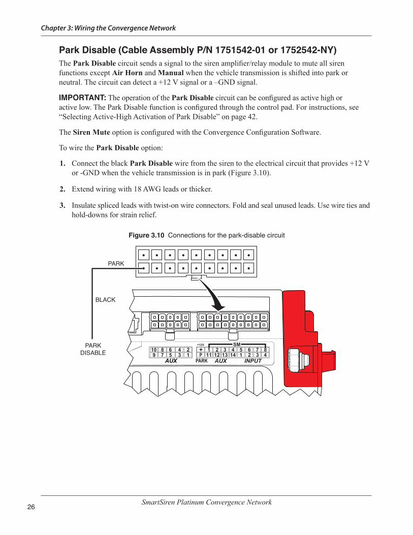
Park Disable (Cable Assembly P/N 1751542-01 or 1752542-NY)The Park Disable circuit sends a signal to the siren amplifier/relay module to mute all siren functions except Air Horn and Manual when the vehicle transmission is shifted into park or neutral. The circuit can detect a +12 V signal or a –GND signal.
IMPORTANT: The operation of the Park Disable circuit can be configured as active high or active low. The Park Disable function is configured through the control pad. For instructions, see “Selecting Active-High Activation of Park Disable” on page 42.
The Siren Mute option is configured with the Convergence Configuration Software.
To wire the Park Disable option:
1. Connect the black Park Disable wire from the siren to the electrical circuit that provides +12 V or -GND when the vehicle transmission is in park (Figure 3.10).
2. Extend wiring with 18 AWG leads or thicker.
3. Insulate spliced leads with twist-on wire connectors. Fold and seal unused leads. Use wire ties and hold-downs for strain relief.
Figure 3.10 Connections for the park-disable circuit
10 8 6 4 29 57 3 1
AUX
2 33
44
5 6 7 8111 1 1 1 12 2 3 4
AUXPARK INPUT
+12V
+ P
SM
BLACK
PARK
PARKDISABLE
Chapter 3: Wiring the Convergence Network
SmartSiren Platinum Convergence Network 27
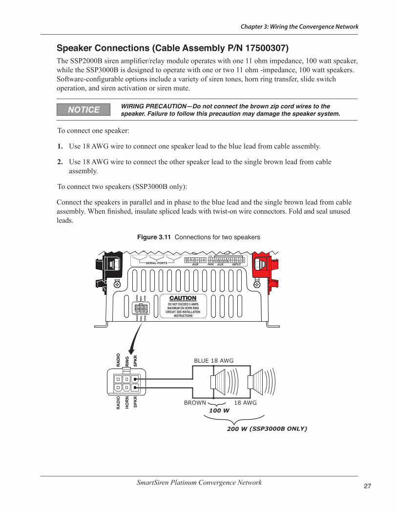
Speaker Connections (Cable Assembly P/N 17500307)The SSP2000B siren amplifier/relay module operates with one 11 ohm impedance, 100 watt speaker, while the SSP3000B is designed to operate with one or two 11 ohm -impedance, 100 watt speakers. Software-configurable options include a variety of siren tones, horn ring transfer, slide switch operation, and siren activation or siren mute.
WIRING PRECAUTION—Do not connect the brown zip cord wires to the speaker. Failure to follow this precaution may damage the speaker system.
To connect one speaker:
1. Use 18 AWG wire to connect one speaker lead to the blue lead from cable assembly.
2. Use 18 AWG wire to connect the other speaker lead to the single brown lead from cable assembly.
To connect two speakers (SSP3000B only):
Connect the speakers in parallel and in phase to the blue lead and the single brown lead from cable assembly. When finished, insulate spliced leads with twist-on wire connectors. Fold and seal unused leads.
Figure 3.11 Connections for two speakers
10 8 6 4 29 57 3 1
AUX
2 33
44
5 6 7 8111 1 1 1 12 2 3 4
AUXPARK INPUT
+12V
+ P
100 W
200 W
BLUE 18 AWG
BROWN 18 AWG
(SSP3000B ONLY)
SERIAL PORTS
RA
DIO
RIN
G
SPK
R
RA
DIO
HO
RN
SPK
R
290A7547
RA
DIO
RIN
G
SPK
R
DO NOT EXCEED 5 AMPSMAXIMUM ON HORN RING
CIRCUIT. SEE INSTALLATION INSTRUCTIONS
RA
DIO
RIN
G
SPK
R

Chapter 3: Wiring the Convergence Network
SmartSiren Platinum Convergence Network28
Horn Ring Transfer (Cable Assembly P/N 17500307)The default setting for the slide switch transfers the horn-ring activation of the siren in Slide Switch 2 and 3. In Slide Switch 2, a press of the horn button activates the Manual tone. In Slide Switch 3, each press of the horn button cycles through a siren function, such as tones or air horn, assigned to horn-ring transfer via the Convergence Configuration Software. In addition, the default configuration for Slide Switch 3 is Siren Dependent Enabled, which restricts siren activation to the slide switch position you select. For example, if you press a button that is assigned a siren tone, the tone only activates when you place the slide switch in the position that is Siren Dependent Enabled.
NOTE: The horn ring circuit can be programmed as active high or active low as described in Chapter 6.
To enable horn-ring control of siren tones, obtain a SPST relay of enough contact-current capacity to activate the vehicle horn:
1. Cut the wire that connects the switch for the vehicle horn ring to the horn or horn relay (Figure 3.12 on page 29).
2. Splice the white/yellow wire from the power cable to the horn ring side of the wire that you cut in step 1.
DETERMINE CURRENT FOR HORN—The horn ring transfer circuit of the siren can switch a maximum of 5 A. Some vehicles do not have a horn relay and consequently will draw more than 5 A when the vehicle horn is activated. Consult your vehicle service manual or a qualified mechanic to determine the current required to activate the horn. If it is less than 5 A, perform step 3. If it is greater than 5 A, perform steps 4 through 9.
3. Splice the white wire from the power cable to the horn side of the cut wire.
4. Mount the SPST relay in a suitable location.
5. Connect the horn side of the wire cut in step 1 to the relay-contact terminal.
6. Determine the “sense” of the vehicle’s horn ring activation circuit. Does the horn circuit require a switched positive (active-high) voltage or switched ground (active-low) for activation?
7. Connect the switched relay-contact terminal to the positive or negative potential you determined in step 6.
8. Connect the white wire from the power cable to one end of the relay coil.
9. Connect the other end of the relay coil to the opposite potential of that connected to the switched relay contact terminal in step 7.
10. Insulate the spliced leads with twist-on wire connectors. Fold and seal unused leads.

Chapter 3: Wiring the Convergence Network
SmartSiren Platinum Convergence Network 29
Figure 3.12 Connections for the horn-ring transfer circuit
SERIAL PORTS
5 A FUSE ON TOP OF SIRENFOR HORN RING
SW
VEHICLE HORNS STEERING COLUMN
SPST RELAY (INSTALLER-SUPPLIED)
TO BATTERYCUT
WIRE
WHITE 18 AWG
WHITE/YELLOW 18 AWG
TO HORN OR HORN RELAY
290A7549
TO HORN RING SIDE OF CUT WIRE
RA
DIO
RIN
G
SPK
R
RA
DIO
HO
RN
SPK
R
TO HORN RING
10 8 6 4 29 57 3 1
AUX
2 33
44
5 6 7 8111 1 1 1 12 2 3 4
AUXPARK INPUT
+12V
+ P
RA
DIO
RIN
G
SPK
R
DO NOT EXCEED 5 AMPSMAXIMUM ON HORN RING
CIRCUIT. SEE INSTALLATION INSTRUCTIONS
RA
DIO
RIN
G
SPK
R
CABLE ASSY.P/N 17500307

Chapter 3: Wiring the Convergence Network
SmartSiren Platinum Convergence Network30
Radio Rebroadcast (Cable Assembly P/N 17500307)To allow incoming two-way radio messages to be amplified by the siren amplifier/relay module and rebroadcast over the siren speakers, connect the brown 18 AWG two-conductor zip-cord across the speaker of the two-way radio (Figure 3.13). Insulate spliced leads with twist-on wire connectors. Fold and seal unused leads. For instructions on adjusting the gain, see “Setting the Gain for Radio Rebroadcast” on page 36.
Figure 3.13 Connections for radio rebroadcast
BRO
WN
ZIP
CO
RD
TWO-WAY RADIO
BRO
WN
ZIP
CO
RD
RADIOSPEAKER
18 AWG
290A7551
RA
DIO
RIN
G
SPK
R
RA
DIO
HO
RN
SPK
R
SERIAL PORTS10 8 6 4 29 57 3 1
AUX
2 33
44
5 6 7 8111 1 1 1 12 2 3 4
AUXPARK INPUT
+12V
+ P
RA
DIO
RIN
G
SPK
R
DO NOT EXCEED 5 AMPSMAXIMUM ON HORN RING
CIRCUIT. SEE INSTALLATION INSTRUCTIONS
RA
DIO
RIN
G
SPK
R
CABLE ASSY.P/N 17500307

Chapter 3: Wiring the Convergence Network
SmartSiren Platinum Convergence Network 31
Connecting the Control Pad In addition to the connection through the 25-foot Convergence Network cable, the control pad has:
■ Connections for four active-low input circuits that activate when pulled to ground. (17500308)
■ Connections to the siren for battery ground (–GND) and +12 Vdc switched by ignition or to battery +12 Vdc for ignition timers (17500308)
■ Connection for optional ignition sense (+12 Vdc) for ignition timers (17500308)
■ Connection for the Federal Signal public address microphone (P/N 258B577-03)
■ 25-foot cable that connects the control pad to the siren amplifier (P/N 1751537-02)
The next sections describe how to connect the control pad to the network.
Connecting the Active-Low Input CircuitsCable assembly P/N 17500308 includes 18-inch, 22 AWG wires for four active-low circuit inputs. Figure 3.14 shows the connectors for the four input leads on the back of the control pad. Similar to the siren relay circuits, Inputs 1 to 4 are most commonly used for circuits that send a signal to the Convergence Network system when a condition in the vehicle changes. Changes in conditions may include the opening of a trunk or door, a rise in vehicle temperature, or the release of a gun lock. The inputs are often used for police vehicle anti-theft devices, intrusion alarms, and temperature monitoring systems for K9 vehicles.
Figure 3.14 Control pad connections
22 AWG
BLACK
RED
INPUT 4 (BLUE)
INPUT 3 (PURPLE)
INPUT 2 (WHITE/YELLOW)
INPUT 1 (GRAY)
TO -GND
290A7553
TO +12 V CONNECTION ACTIVATED BY IGNITION
(OPTIONALLY TO +12 Vdc BATTERY IF USING IGNITION TIMERS)
INSTALLERSUPPLIED
INPUT 1 THROUGH 4GROUND ACTIVE
(ACTIVE LOW)
−GND
IGNITION INPUT(YELLOW)
(OPTIONAL)

Chapter 3: Wiring the Convergence Network
SmartSiren Platinum Convergence Network32
Each input circuit can be programmed to activate with an installer-supplied switch having a current capacity of 100 mA , with the SSP3000B control pad, or with the two-way switches on the steering wheel of the Ford Police Interceptor. For the location of the vehicle 14-way connector for the ground-sourcing outputs, refer to the Ford Police Interceptor Modifier Manual.
For programming information, see the Convergence Configuration Software Manual. For a chart showing the default configurations for the control pad and for the steering wheel switches connected to the four low-input circuits, see page 45 for the SSP2000B and page 46 for the SSP3000B.
Connecting Power to the Control Pad (without Ignition Timer)The red and black leads from the control pad supply power to the SmartSiren Platinum System when the vehicle ignition key is in the ignition (start) position (Figure 3.16 on page 34).
To connect the control pad to ignition power:
1. Use a multimeter to determine which source provides power when the vehicle key is in the ignition position.
2. Connect the red lead from the control pad to the switched side of the vehicle ignition harness. Do not splice the red lead to the power leads for accessories. Extend the lead with 22 AWG leads or thicker.
3. Connect the black lead from the control pad to negative ground. Extend the lead with 22 AWG leads or thicker.
4. Insulate spliced leads with twist-on wire connectors. Fold and seal unused leads. Use wire ties and hold-downs for strain relief.
Connecting Power to the Control Pad (with Ignition Timer)The SmartSiren Platinum system has an optional ignition sense timer that enables public safety personnel to use mobile equipment for a set period of time with the engine turned off, insuring the battery has enough power to start the vehicle. Mobile equipment includes any device that is charged from the vehicle battery or requires power to upload wireless data, such as flashlights, laptops, radios, and digital recorders.
Four different time delays are available ranging from immediately off to four hours on. They are assigned the input relays with the Convergence Network Configuration software. Do not connect anything to the input relays selected for the ignition timer. Program any timed equipment through the control pad button with the Convergence Network Configuration Software.
The red and black leads from the control pad supply power from the vehicle battery to the SmartSiren Platinum System. The yellow ignition wire activates the system when the ignition key is in the start position.
To connect the control pad to ignition power:
1. Use a multimeter to determine which source provides power when the vehicle key is in the ignition position.

Chapter 3: Wiring the Convergence Network
SmartSiren Platinum Convergence Network 33
2. Connect the red lead from the control pad to the switched side of the vehicle ignition harness. Extend the lead with 22 AWG leads or thicker.
3. Connect the yellow lead from the control pad to a constant +12 Vdc from the battery. Do not splice the red and yellow leads to the power leads for accessories. Extend the lead with 22 AWG leads or thicker.
4. Connect the black lead from the control pad to negative ground. Extend the lead with 22 AWG leads or thicker.
5. Insulate spliced leads with twist-on wire connectors. Fold and seal unused leads. Use wire ties and hold-downs for strain relief.
Connecting the Federal Signal Microphone (P/N 258B8577-03)The microphone provides high quality voice reproduction in for public address over the siren speakers. The microphone push-to-talk switch overrides all siren functions, except radio rebroadcast, for instant PA use. The microphone connection is not required for the siren to operate properly.
To attach the microphone cable to the control pad, insert the modular telephone-type plug in the microphone jack until it locks. For instructions on adjusting the PA volume, see “Setting the Gain for Public Address (Microphone Volume)” on page 37.
Figure 3.15 Microphone connected to the control pad
SERIAL PORTS10 8 6 4 29 57 3 1
AUX
2 33
44
5 6 7 8111 1 1 1 1+1
2v
2 2 3 4
SM
AUX INPUT
PAR
K
DIS
AB
LE
RA
DIO
RIN
G
SPK
R
PAR
K
DIS
AB
LE
RA
DIO
HO
RN
SPK
R
-+
-+ SERIAL PORTS
DO NOT EXCEED 5 AMPSMAXIMUM ON HORN RING
CIRCUIT. SEE INSTALLATION INSTRUCTIONS
CONTROL PAD MUST BE CONNECTED TO
ONE OF THESE LOWER SERIAL PORTS
FEDERAL SIGNAL MICROPHONE (P/N 258B577-03)

Chapter 3: Wiring the Convergence Network
SmartSiren Platinum Convergence Network34
Connecting the Siren to the BatteryThis section has instructions for making the final electrical connections from the siren to the battery. These connections supply power to the SmartSiren Platinum System. Required are an installer-supplied in-line fuse and wiring of an amperage capacity sufficient to handle the total vehicle electrical loads.
BATTERY EXPLOSION—To avoid a battery explosion, always disconnect the negative battery cable first and reconnect it last. Avoid causing a spark when connecting near or to the battery. The gases produced by a battery can cause a battery explosion that could result in vehicle damage and serious injury.
HIGH CURRENT ARCING—Do not connect this system to the vehicle battery until ALL other electrical connections are made and you have verified that no shorts exist. High current conductors can cause hazardous sparks or burning wire resulting in electrical fires.
Preparing to Connect the Power LeadsBefore connecting the amplifier/relay module to the battery, ensure that your final installation goes smoothly by taking these preparatory steps:
1. Visually check all connections and wiring to ensure that all connections are correct and secure.
2. Ensure that there are no loose strands or other bare wires that may cause a short circuit. Also, all wires must be protected from any sharp edges that could eventually cut through the insulation.
3. Verify that are other electrical connections are completed and that no shorts exit.
4. Use an ohmmeter to verify that a short circuit does not exist between the positive (+) and negative (–) battery cable leads. Also, there must be no short circuits between the positive wires and the vehicle chassis.
Figure 3.16 Negative ground connection for the control pad
TERMINAL
0.266" X 11/16", SS FLAT WASHER (2)
1/4"-20, SS EXT. TOOTH LOCK WASHER (4)
1/4"-20, SS KEPS NUT (2)
POWER LEAD CONNECTIONS ARELOCKED BETWEEN LOCK WASHER AND KEPS NUT
290A6424

Chapter 3: Wiring the Convergence Network
SmartSiren Platinum Convergence Network 35
Connecting the Power Leads to the Vehicle BatteryThe installer-supplied red (positive) and black (negative ground) power leads from the siren amplifier/relay module to the vehicle battery should be as short and direct as possible.
1. Route the red lead and black lead from the siren to the battery.
2. Crimp a ring terminal on the red lead and connect it to the positive (+12V) battery terminal.
3. Crimp a ring terminal on the black lead and connect it through an in-line fuse to the negative (–NEG) battery terminal. The fuse must be of an amperage capacity sufficient to handle the total vehicle electrical loads.
4. Reconnect the positive cable to the vehicle battery and tighten the clamp.
5. Reconnect the negative cable to the vehicle battery and tighten the clamp.
SmartSiren Platinum Convergence Network36
CHAPTER 4Setting the Gain for Radio Rebroadcast and PA
The radio rebroadcast feature allows incoming two-way radio messages to be amplified by the siren amplifier/relay module and rebroadcast over the siren speakers of the SSP3000B system. The feature overrides all sirens functions. Button 7 is programmed as the default control for radio rebroadcast. The gain control for radio rebroadcast is a recessed potentiometer on the front of the siren amplifier/relay module (Figure 4.2 on page 37). Wiring connections are described in “Radio Rebroadcast (Cable Assembly P/N 17500307)” on page 30.
For public address, the Smart Siren Platinum System includes a microphone that connects to a serial port on the back of the control pad. When the operator presses the microphone push-to-talk button and speaks into the microphone, the operator’s voice is amplified and broadcast over the siren speakers. The control for adjusting the PA gain is a potentiometer on the back of the control pad (Figure 4.3 on page 37).
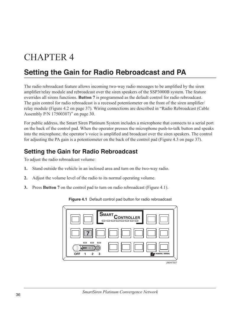
Setting the Gain for Radio RebroadcastTo adjust the radio rebroadcast volume:
1. Stand outside the vehicle in an inclosed area and turn on the two-way radio.
2. Adjust the volume level of the radio to its normal operating volume.
3. Press Button 7 on the control pad to turn on radio rebroadcast (Figure 4.1).
Figure 4.1 Default control pad button for radio rebroadcast
7
290A7557

Chapter 4: Setting the Gain for Radio Rebroadcast and PA
SmartSiren Platinum Convergence Network 37
4. Stand outside of the vehicle and note the volume level of the radio rebroadcast. If the volume is too loud or too soft, insert a small flat-head screwdriver in the gain control port for radio rebroadcast (RAD VOL) on the front of the siren amplifier/relay module (Figure 4.2). Turn the screwdriver counter-clockwise to increase the volume until audio feedback (squeal) occurs or clockwise to decrease the volume until squeal ceases.
NOTE: Audio feedback depends upon the microphone gain, open windows, speaker placement, and the proximity of reflecting surfaces such as walls, buildings, or other vehicles.
5. To turn off radio rebroadcast, press Button 7.
Figure 4.2 Gain control for radio rebroadcast (siren amplifier/relay module)
RADIO REBROADCAST GAIN CONTROL 290A7555
Setting the Gain for Public Address (Microphone Volume)To adjust the PA gain:
1. Stand outside the vehicle in an enclosed area and press the push-to-talk button on the control pad microphone. Speak into the microphone in a normal tone of voice.
2. If the speaker volume is too loud or too soft, insert a small screwdriver in the PA gain control port (PA VOL) on back of the control pad. (Figure 4.3). Turn it counter-clockwise to increase the volume until audio feedback (squeal) occurs or clockwise to decrease the volume.
Figure 4.3 Gain control for PA (control pad)
PA GAIN CONTROL(MIC VOLUME)290A7558
TO MICROPHONE
TO CONVERGENCE NETWORK

SmartSiren Platinum Convergence Network38
CHAPTER 5Mounting the Siren and Control Pad
The next step in the installation after wiring and connecting the SSP3000B/SSP2000B system is to permanently mount the siren amplifier/relay module and control pad in the vehicle. Verify that the mounting locations you selected earlier are safe for installing these components. Before proceeding, review the following precautions before mounting the equipment.
AIRBAG DEPLOYMENT—Do not install equipment or route wiring in the deployment path of an airbag. Failure to observe this warning will reduce the effectiveness of the airbag or potentially dislodge the equipment, causing serious injury or death.
SEAT REMOVAL PRECAUTION—If a vehicle seat is temporarily removed, verify with the vehicle manufacturer if the seat needs to be recalibrated for proper airbag deployment.
UNIT REQUIRES AIR FLOW (SSP3000B ONLY)—The siren amplifier/relay module is cooled by an internal fan. Do not install it in areas where the air flow is restricted. Do not mount the unit near a heater duct or under the hood.
UNIT IS NOT WATERPROOF—The housing of the siren amplifier/relay module is NOT waterproof. The module must be mounted in a location that is sheltered from falling rain, snow, standing water, etc.
DRILLING PRECAUTIONS—When drilling holes, check the area you are drilling into to be sure you do not damage vehicle components while drilling. All drilled holes should be de-burred and all sharp edges should be smoothed. All wire routings going through drilled holes should be protected by a grommet or convolute/split loom tubing.
Mounting the Siren Amplifier/Relay ModuleInstaller-supplied #10-32 mounting hardware is required to mount the siren amplifier/relay module.
Tools needed:
• #18 tap drill for steel and iron
• Phillips screwdriver
• Pencil or felt-tip pen for marking drill locations

Chapter 5: Mounting the Siren and Control Pad
SmartSiren Platinum Convergence Network 39
To mount the siren amplifier/relay module in the vehicle:
1. Use the base of the siren amplifier/relay module as a template (Figure 5.1) or the dimensions shown in Figure 5.1 to mark the centers of the four mounting holes.
Figure 5.1 Slots for mounting hardware
1.05 in(2.66 cm)
7.49 in(19.03 cm)
7.94 in(20.17 cm)
4.50 in(11.43 cm)
MOUNTING SLOTS (4 PLACES)
INSTALLER-SUPPLIED #10-32 MOUNTING HARDWARE REQUIRED
290A7560
2. Tap and drill the center of the four mounting holes.
3. Center the slots in the base of the siren amplifier/relay module over the drilled holes and secure it with the installer-supplied #10-32 mounting hardware.
Mounting the Control PadThe control pad comes with two mounting brackets and mounting hardware.
Tools needed:
• Drill with #9 drill bit
• Phillips screwdriver
• 7/16" nut driver
• Pencil or felt-tip pen for marking drill position locations
To mount the control pad:
1. Secure a bracket to the control pad with the 6-32 x 1/4" Phillips screws and #6 lock washers (Figure 5.2 on page 40).
2. Using a 7/16" nut driver, secure the other bracket to the control pad/bracket assembly with the 1/4-20 x 3/4" hex head screws and 1/4" lock washers (Figure 5.3 on page 40).

Chapter 5: Mounting the Siren and Control Pad
SmartSiren Platinum Convergence Network40
3. Use the mounting bracket as a template and scribe two drill position marks at the selected mounting location.
Figure 5.2 Bracket attached to back of control pad
NETW
OR
K C
ON
NEC
TION
ON
LY! A N
ON
-NETW
OR
K C
ON
NEC
TION
WILL R
ESULT IN
DA
MA
GE TO
DEVIC
ES. DO
NO
T CO
NN
ECT TO
PC.
For further information see instructions or call 1-800-433-9132.
PCC
ON
NEC
TO
NLY
!W
AR
NIN
G
290A7561
CONTROL PAD
BRACKET (1 OF 2)
NOTE: USE ONE OF THE THREESETS OF HOLES IN THE PIVOT BRACKET TO BEST POSITION THE CONTROL PAD.
#6-32 x 1/4" SCREW,PHL. PAN HD (2)
PEM-NUT (ATTACHEDTO BRACKET)
#6 SPLIT LOCK WASHER (2)
4. Drill two pilot mounting holes at the drill position marks.
5. Secure the mounting bracket to the mounting surface with the #10 thread-forming screws (Figure 5.3).
6. To adjust the angle of the control pad, loosen the hinge screws, tilt the control pad forward or backward, then securely tighten the screws.
Figure 5.3 Brackets attached to control pad and mounting surface
NETW
OR
K C
ON
NEC
TION
ON
LY! A N
ON
-NETW
OR
K C
ON
NEC
TION
WILL R
ESULT IN
DA
MA
GE TO
DEVIC
ES. DO
NO
T CO
NN
ECT TO
PC.
For further information see instructions or call 1-800-433-9132.
!W
AR
NIN
G
290A7562PILOT HOLES (2)
PEM-NUTS (ATTACHED TO BRACKET)
BRACKET (2 OF 2)
MOUNTING SURFACE
MOUNTING HOLES
#10 SCREW, THREAD-FORMING (2)
1/4-20 x 3/4" HINGE SCREW, HEX HEAD (2)
1/4" LOCK WASHER, EXT. TOOTH (2)
PCC
ON
NEC
TO
NLY

SmartSiren Platinum Convergence Network 41
CHAPTER 6Setting Control Pad Options
The SmartSiren Platinum control pad has these configurable features:
◆ A notification beep that sounds every ten seconds when one or more functions or devices in the system, such as a lightbar, is activated. The default setting is “on.”
◆ Step-through selection of one of four levels of LED dimming, including “off.” The default setting is at the brightest level.
◆ Selection of active-high activation of the park disable circuit.
◆ Selection of active-high activation of the horn-ring transfer circuit.
◆ The operation and control of network devices, which are resettable to the factory-default configuration (see Figure 7.1 on page 45 or Figure 7.2 on page 46 and the Convergence Configuration Software Manual, doc. no. 2562418).
To help you confirm your selection, the button you press glows while the control pad beeps every 10 seconds. Additionally, one or more amber LEDs turn on in the row at the top of the control pad (Figure 6.1 on page 42). These LEDs identify the button and its associated setting.
Entering Program ModeTo set the keypad options, first enter Program Mode:
1. Press and hold Button 6 while powering up the control pad (Figure 6.1 on page 42).
2. During the long beep, release Button 6. The control pad beeps continuously.
3. Verify that the first amber LED is on.
Turning Off or On the 10-Second Notification BeepThe control pad beeps every 10 seconds when you are in Program Mode. To turn the beep off or on:
1. While in Program Mode, press Button 12 (Figure 6.1 on page 42).
2. To continue, select another setting to change or press Button 13 to exit Program Mode. Verify that the last amber LED turns on when you exit.

Chapter 6: Setting Beep and LED Options for the Control Pad
SmartSiren Platinum Convergence Network42
Figure 6.1 LEDs and buttons associated with Program Mode settings
6 7 8 9 10 12 13
6 7 8 1210 139
290A7563
Indicates that the Ethernet is on for system configuration and the control pad is in Program Mode (see the Convergence Configuration Software Manual P/N 2562418)
Indicates that the control pad is ready to be reset to the factory default configuration
Indicates that the 10-second beep audible in Program Mode selected for ON or OFF
Indicates that the button LEDs are selected for DIM or OFF Indicates that the Park Disable circuit is selected for active high (ON) or active low (OFF) activation
Exits Program Mode
Indicates that the Horn Ring circuit is selected for active high (ON) or active low (OFF) activation
Selecting Active-High Activation of Horn-Ring TransferFor instructions on connecting the horn-ring circuit for siren-tone control, see “Horn Ring Transfer (Cable Assembly P/N 17500307)” on page 28.
The default setting is active-low. To select active-high activation of the Park Disable feature:
1. While in Program Mode, press Button 10. LED 10 in Figure 6.1 turns on.
2. To continue, select another setting to change or press Button 13 to exit Program Mode. Verify that the last amber LED turns on when you exit.
Selecting Active-High Activation of Park DisableFor instructions on connecting the control pad to the Park Disable circuit, see “Park Disable (Cable Assembly P/N 1751542-01 and 1752542-NY)” on page 26.
The default setting is active-low. To select the active-high activation of the Park Disable feature:
1. While in Program Mode, press Button 9. LED 9 in Figure 6.1 turns on.
2. To continue, select another setting to change or press Button 13 to exit Program Mode. Verify that the last amber LED turns on when you exit.

Chapter 6: Setting Beep and LED Options for the Control Pad
SmartSiren Platinum Convergence Network 43
Dimming or Turning Off the Button LEDsTo dim or turn off the button LEDs:
1. While in Program Mode, press Button 8 up to four times to step though decreasing levels of brightness (Figure 6.1 on page 41). To turn off the LEDs, press Button 8 a fifth time.
2. To continue, select another setting or press Button 13 to exit Program Mode. Verify that the last amber LED turns on when you exit.
Resetting to the Factory Default ConfigurationTo reset the operation and control of network devices to the factory default:
1. While in Program Mode, press Button 7 (Figure 6.1 on page 41).
2. To continue, select another setting to change or press Button 13 to exit Program Mode. Verify that the last amber LED turns on when you exit.
Exiting Program ModeTo exit Program Mode
1. Press Button 13 (Figure 6.1 on page 41).
2. Verify that the last amber LED turns on when you exit.

SmartSiren Platinum Convergence Network44
CHAPTER 7 Testing the Convergence Network Installation
SOUND HAZARD—All effective sirens and horns produce loud sounds (120 dB) that may cause permanent hearing loss. Always minimize your exposure to siren sound and wear hearing protection. Do not sound the siren indoors or in enclosed areas where you and others will be exposed to the sound.
LIGHT HAZARD—To be an effective warning device, an emergency warning system produces bright light that can be hazardous to your eyesight when viewed at a close range. Do not stare directly into this lighting product at a close range or permanent damage to your eyesight may occur.
The control pad is programmed with a default configuration that you can use to quickly check your initial installation of the SSP3000B system before you configure the control pad. For illustrations showing the default configurations for the control pad and for the steering wheel switches (if connected to the four control pad input circuits), see page 45 for the SSP2000B and page 46 for the SSP3000B. When you test the system, be sure to note the status of the LED indicators in the externally mounted fuses of the siren amplifier/relay module. Also note the activity of the LEDs just below the surface of the module. The illustrations on the following pages describe what each LED indicates. Also verify that the 10-second function notification beep and lightning options of the control pad work as expected.
In addition, test all vehicle functions, including horn operation, vehicle safety functions, and vehicle lighting systems for proper operation. Ensure that the installation has not affected the vehicle operation or changed any vehicle safety functions or circuits. Do not test the sound and light system of the vehicle while driving. Operating the vehicle warning system may pose a hazard to the operator and other drivers if the system does not function as expected. Test the vehicle only in a controlled environment. After testing is complete, provide a copy of this manual to the instructional staff and all operating personnel.

Chapter 7: Testing the Convergence Network
SmartSiren Platinum Convergence Network 45
Figure 7.1 SSP2000B default configuration for control pad
Signal Master
Step-ThroughLeft, Right, Center Out
RearLightbar
WarnStep-Through
Warn Patterns
1 to 4Rear
Lightbar
SSP2000BButton 14
Button Control:Push On/Off
Lightbar:Dimming
Button 15Button Control:
Push On/OffRear Light
Cutoff
Button 6Button Control:
ExclusiveSiren: Standby
Button 7Button Control:
ExclusiveSiren: Radio
Button 8Button Control:
Push On/Off
Lightbar: Scene LightActive Hi/Lo10 A Relay 9
Relay Function:
Steady OnActive HiOpen Off
Button 9Button Control:
ExclusiveSiren: Wail
Siren Control: On Power Up
Button 10Button Control:
ExclusiveSiren: Yelp
Button 11Button Control:
ExclusiveSiren: Priority
Button 12Button Control:
MomentarySiren: Manual
Button 13Button Control:
MomentarySiren: Air Horn
Slide Switch 1Button Control:
MomentaryFront Light
Cutoff
LightbarFront Light
CutoffPattern 10
Relay: 10 A Relay 1
Relay Function:
Active HighSteady On
Slide Switch 2Button Control:
MomentaryLightbar
Pattern 17Horn Ring TransferRelay:
Active H/L 10 A Relays
1–3Relay
Function:Steady OnActive HighOpen Off
Slide Switch 3Button Control:
MomentaryFlash Take-down/Alley
Lightbar Pattern 26
Siren Dependent
EnabledHorn Ring Transfer
Active High 10 A Relays
1–5Relay
Function: Steady On
Active High,Open Off
Button 1Button Control:
Push On/OffLightbar: Left Alley
Relay Relay 6
Active H/LRelay
Function:Steady OnActive HighOpen Off
Button 2Button Control:
Push On/OffLightbar:
TakedownsRelay
Function:Steady OnActive HighOpen Off
Button 3Button Control:
Push On/OffLightbar:
Right AlleyRelay
Function:Steady OnActive HighOpen Off
Button 4Button Control:
Timer:8 SecondsLightbar:
Intersection Pattern 22
Button 5Button Control:Security Timer:
8 SecondsActive High/Low 10 A Relay 10:
Relay Function:
Steady OnActive HighOpen Off
Figure 7.2 Default configuration for steering wheel switches wired to control pad
1
2AUX
3
4AUX
SLIDE SWITCH 1
SLIDE SWITCH 2
SLIDE SWITCH 3
BUTTON 2

Chapter 7: Testing the Convergence Network
SmartSiren Platinum Convergence Network46
Figure 7.3 SSP3000B default configuration for control pad
Signal Master
Step-ThroughLeft, Right, Center Out
Rear LightbarRear
External Dis-crete 8-Head
Version
WarnStep-Through
Warning Patterns
1 to 4Rear
LightbarExternal Dis-crete 8-Head
Version
SSP3000BButton 14
Button Control:Push On/Off
Lightbar:Dimming
Button 15Button Control:
Push On/OffRear Light
Cutoff
Button 6Button Control:
ExclusiveSiren: Standby
Button 7Button Control:
ExclusiveSiren: Radio
Button 8Button Control:
Push On/OffActive High/
Low10 A Relay 9
Relay Function:
Steady OnActive HiOpen Off
Button 9Button Control:
ExclusiveSiren: Wail
Siren Control: On Power Up
Button 10Button Control:
ExclusiveSiren: Yelp
Button 11Button Control:
ExclusiveSiren: Priority
Button 12Button Control:
MomentarySiren: Manual
Button 13Button Control:
MomentarySiren: Air Horn
Slide Switch 1Button Control:
MomentaryLightbar
Pattern 10Front Light
CutoffRelay:
Active High/Low
10 A Relay 1Relay
Function:Steady OnActive HighOpen Off
Slide Switch 2Button Control:
MomentaryLightbar
Pattern 17Horn Ring TransferRelay:
Active High/Low
10 A Relays 1–3
Relay Function:
Steady OnActive HighOpen Off
Slide Switch 3Button Control:
MomentaryFlash Take-down/Alley
Lightbar Pattern 26
Siren Dependent
EnabledHorn Ring Transfer
Active High/Low
10 A Relays 1–5
Relay Function:
Steady OnActive High,
Open Off
Button 1Button Control:
Push On/OffLightbar: Left Alley
Active High/Low
10 A Relay 6Relay
Function:Steady On
Active High,Open Off
Button 2Button Control:
Push On/OffLightbar:
TakedownsActive High/
Low 10 A Relay 7
Relay Function:
Steady OnActive HighOpen Off
Button 3Button Control:
Push On/OffLightbar:
Right AlleyActive High/
Low 10 A Relay 8
Steady OnActive HighOpen Off
Button 4Button Control:
Timer:8 SecondsLightbar:
Intersection Pattern 22
Button 5Button Control:Security Timer:
8 SecondsActive High/Low 10 A Relay 10:
Relay Function:
Steady OnActive HighOpen Off
Figure 7.4 Default configuration for steering wheel switches wired to control pad
1
2AUX
3
4AUX
SLIDE SWITCH 1
SLIDE SWITCH 2
SLIDE SWITCH 3
BUTTON 2

Chapter 7: Testing the Convergence Network
SmartSiren Platinum Convergence Network 47
LIGHTBAR ACTIVE: LED glows in the SSP3000B when the
lightbar is flashing.
AUX PWR: LED glows in the SSP3000B when battery power and serial cable power are present.
SM PWR: LED glows in the SSP3000B when the Signal- Master has power.SM ON: LED glows in the SSP3000B when the SignalMaster flashes a pattern.
10 A AUX 1–10: 10 A fuses for 10 A auxiliary solid-state relays. Relays 9/10 can be configured as 12 Vdc out or ground out. (Relays 7, 8, and 9 are not available on the SP2000B.)
INPUT 1–4: LEDs glow in the SSP3000B when an input is receiving a signal. Voltage and amperage are required for the signal.
290A7564
SM 20A: 20 A fuse for the SignalMaster. (SSP3000B only)
Figure 7.5 LED indicators and fuses on upper part of siren amplifier/relay module
AUX 11–14: LED glows when the output is on for a 2 A auxiliary solid-state relay. These relays are active-high only and are internally protected by electronic short-circuit detection circuits.
AUX 1–10: LED glows in the SSP3000B when the output is on for a 10 A auxiliary solid-state relay. Relays 9/10 can be configured as 12 Vdc out or ground out. Relays 1 to 8 are active high only.
RX (Receive): LED flashes in the SSP3000B when the relay module receives a message
on the FS Convergence network.
TX (Transmit): LED flashes in the SSP3000B when the relay module transmits a message
on the FS Convergence network.
In the SSP3000B each external mini ATM fuse has an integrated LED that glows when the fuse is blown. The table identifies the color code and amperage.
Color Amp.
Tan
Red
Yellow

Chapter 7: Testing the Convergence Network
SmartSiren Platinum Convergence Network48
Figure 7.6 LED indicators on lower label of siren amplifier/relay module
ON: LED glows when the network has power.
PWR: LED glows when the siren amplifier has power.
RAD VOL: Screw for adjusting the factory-set radio volume.
SIREN 20 A: 20 A fuse for the siren
5 A HORN: 5 A fuse for horn-ring circuit
PA VOL: Screw for adjusting the factory-set public address volume. (For special models with
the microphone connected to the siren.) This feature is unavailable for most models.)
290A7568

Chapter 7: Testing the Convergence Network
SmartSiren Platinum Convergence Network 49
Figure 7.7 LED programming indicators on the control pad
SLIDE SWITCH LEDs: LEDs above the slide switch glow when the system is on (1=green, 2=amber, 3=red). The LED brightens above the position in which the slide switch is placed.
SmartSiren® LEDs: LEDs mimic these active SignalMaster patterns: Left, Right, Center-Out, or Warn patterns 1 to 4. They also indicate when a programmed feature of the key pad is active (see “Setting Control Pad Options” on page 41.)
Button LEDs: All buttons on the control pad glow when the system is on. Pressed buttons blink to indicate
that the function they control is active.
The control pad legends in the illustration are for a typical configuration. The SSP3000B/SSP2000B kit includes additional legends. All buttons are programmable. For instructions for programming the control pad, see the “SSP3000B Control Pad Configuration Software Manual” (doc. no. 2562418).
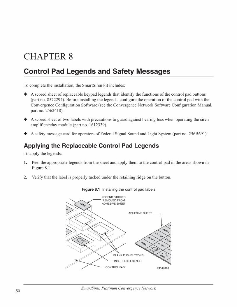
SmartSiren Platinum Convergence Network50
CHAPTER 8 Control Pad Legends and Safety Messages
To complete the installation, the SmartSiren kit includes:
◆ A scored sheet of replaceable keypad legends that identify the functions of the control pad buttons (part no. 8572294). Before installing the legends, configure the operation of the control pad with the Convergence Configuration Software (see the Convergence Network Software Configuration Manual, part no. 2562418).
◆ A scored sheet of two labels with precautions to guard against hearing loss when operating the siren amplifier/relay module (part no. 1612339).
◆ A safety message card for operators of Federal Signal Sound and Light System (part no. 256B691).
Applying the Replaceable Control Pad LegendsTo apply the legends:
1. Peel the appropriate legends from the sheet and apply them to the control pad in the areas shown in Figure 8.1.
2. Verify that the label is properly tucked under the retaining ridge on the button.
Figure 8.1 Installing the control pad labels
DOOR
AREA
P
AUX 1WAIL
WAIL
DOMAUX 2
A / HAU
Y
RIGHTALLEY
E
290A6323
MAN
LEGEND STICKER REMOVED FROM ADHESIVE SHEET
ADHESIVE SHEET
BLANK PUSHBUTTONS
INSERTED LEGENDS
CONTROL PAD

Chapter 8: Control Pad Legends and Safety Messages
SmartSiren Platinum Convergence Network 51
Distributing the Safety Message CardGive the operator of the system the card entitled “Safety Message to Operators of Federal Signal Light/Sound Systems” (part no. 256B691) (Figure 8.2). The operator must read and understand the safety instructions and keep the card in the vehicle for reference.
Applying the Siren Safety Labels in the VehicleThe kit includes a sheet of two labels with siren safety messages (part no. 1612339) (Figure 8.2). These labels must be installed in the vehicle in which the system is installed. Install these labels in areas that are clearly visible to operators and passengers. Do not install the labels in locations that would impair the operators’ abilities to operate the vehicle. Never install the labels in areas where airbags may deploy.
Figure 8.2 Safety message card (left) and siren safety labels (right)

SmartSiren Platinum Convergence Network52
CHAPTER 9Safety Messages to Personnel Servicing Federal Signal Electronic Sirens
The people’s lives depend on your proper servicing of Federal Signal products. It is important to read and follow all instructions shipped with the products. |In addition, listed below are some other safety instructions and precautions you should follow:
• Read and understand all instructions in this manual before servicing the electronic siren or control pad.
• To properly service an electronic siren or control pad, you must have a good understanding of automotive electrical procedures and systems, along with proficiency in the installation and service of safety warning equipment. Always refer to the vehicle service manuals when performing service on a vehicle.
• Electronic repairs must be performed by a qualified and competent electronics technician.
• Your hearing and the hearing of others, in or close to your emergency vehicle, could be damaged by loud sounds. This can occur from short exposures to very loud sounds or from longer exposures to moderately loud sounds. For hearing conservation guidance, refer to federal, state, or local recommendations. OSHA Standard 1910.95 offers guidance on “Permissible Noise Exposure.”
• All effective sirens and horns produce loud sounds (120 dB) that may cause permanent hearing loss. Always minimize your exposure to siren sound and wear hearing protection. Do not sound the siren indoors or in enclosed areas where you and others will be exposed to the sound.
• Do NOT connect this system to the positive terminal of the battery until servicing is complete and you have verified that there are no short circuits to ground.
• For the electronic siren to function properly, the ground connection must be made to the NEGATIVE battery terminal.
• After repair, test the electronic siren and speaker system to ensure that it is operating properly.
• Federal Signal siren amplifiers and speakers are designed to work together as a system. Combining a siren and speaker from different manufacturers may reduce the warning effectiveness of the siren system and may damage the components. You should verify or test your combination to make sure the system works together properly and meets both federal, state and local standards or guidelines.
Failure to follow all safety precautions and instructions may result in property damage, serious injury, or death.

SmartSiren Platinum Convergence Network 53
CHAPTER 10Servicing the Convergence Network System
Federal Signal recommends that the siren amplifier/relay module and control pad be returned to your local distributor or Federal Signal for service. External components such as cabling, fuses, and the red and black insulators are available as replacement parts (see Table 10.1 on page 59). With the exception of the slide switch in the control pad, there are no other user-serviceable parts within the control pad or the siren amplifier/relay module. After servicing the system, test it to ensure that it is operating properly. For more information, see “Testing the Convergence Network Installation” on page 44.
Replacing the Slide SwitchThe slide switch can be removed from the control pad for replacement or service without disassembling the entire control pad. The slide switch is secured to the front of the control pad by a bezel and two 1/4"-20 x 3/4" screws. The switch is connected to the four-pin J3 connector on the back of control pad assembly, which lies below the logic control and power control PCBs and is easily accessible.
STATIC SENSITIVE DEVICE—The circuitry of the control pad can be damaged by electrostatic discharge. Follow anti-static procedures removing the slide switch.
Tools needed:
• 7/16" nut driver
• Small Phillips screwdriver
• Small needle-nose pliers
• 1/64" hex key wrench
Dismounting and Disconnecting the Control PadTo remove the control pad:
1. Use a 7/16" nut driver to remove the two 1/4-20 x 3/4" hinge screws securing the two mounting brackets together. Retain the screws and the two 1/4" external-tooth lock washers (Figure 10.1 on page 54).
2. Remove the two #6-32 x 1/4 Phillips screws securing the bracket to the rear of the control pad (Figure 10.2 on page 54). Retain the screws and the two #6 lock washers.
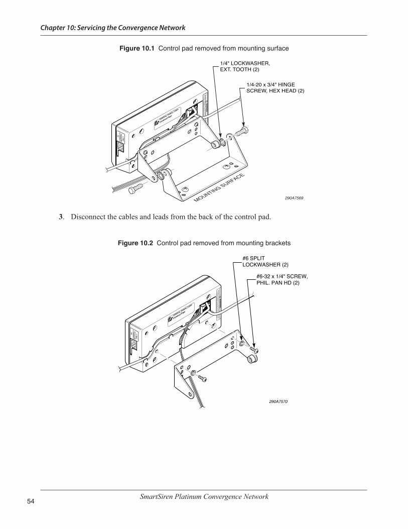
Chapter 10: Servicing the Convergence Network
SmartSiren Platinum Convergence Network54
Figure 10.1 Control pad removed from mounting surface
NETW
OR
K C
ON
NEC
TION
ON
LY! A N
ON
-NETW
OR
K C
ON
NEC
TION
WILL R
ESULT IN
DA
MA
GE TO
DEVIC
ES. DO
NO
T CO
NN
ECT TO
PC.
For further information see instructions or call 1-800-433-9132.
!W
AR
NIN
G
PCC
ON
NEC
T
ON
LY
1/4-20 x 3/4" HINGE SCREW, HEX HEAD (2)
1/4" LOCKWASHER,EXT. TOOTH (2)
MOUNTING SURFACE
290A7569
3. Disconnect the cables and leads from the back of the control pad.
Figure 10.2 Control pad removed from mounting brackets
290A7570
#6-32 x 1/4" SCREW,PHIL. PAN HD (2)
#6 SPLIT LOCKWASHER (2)
NETW
OR
K C
ON
NEC
TION
ON
LY! A N
ON
-NETW
OR
K C
ON
NEC
TION
WILL R
ESULT IN
DA
MA
GE TO
DEVIC
ES. DO
NO
T CO
NN
ECT TO
PC.
For further information see instructions or call 1-800-433-9132.
PCC
ON
NEC
TO
NLY
!W
AR
NIN
G

Chapter 10: Servicing the Convergence Network
SmartSiren Platinum Convergence Network 55
Replacing the Slide Switch in the Control PadTo replace the slide switch:
1. Remove and retain the four Phillips #6-32 x 5/16" screws securing the control pad base to the control pad assembly (Figure 10.3).
2. Remove and retain base of the control pad.
3. Note the orientation of the wires of the slide switch connector. Unplug it from the four-pin J3 connector on the control pad assembly.
4. Note the orientation of the slide switch knob. Use a 1/64" hex key wrench to loosen and remove the set screw securing the knob to the shaft. Retain the set screw and knob.
5. Loosen and remove the two #4-40 x 5/16" Phillips head screws securing the slide switch bezel to the control pad assembly. Retain the screws.
6. Place the new switch assembly in position with the knob in the same orientation as the old switch.
7. Secure the bezel to the control pad assembly with the two #4-40 x 5/16" Phillips head screws.
8. Plug the slide switch connector into the four-pin J3 connector on the control pad assembly. Ensure that the wires on the connector face the edge of the board.
9. Secure the control pad base to the control pad assembly with the four #6-32 x 5/16" Phillips screws.
Figure 10.3 Slide switch removed from control pad
CONTROL PAD ASSY.
SLIDE SWITCH ASSY.
290A6363B
CONTROL PAD BASE
SCREW, #6-32 X 5/16", SEMS PAN HEAD, PHILLIPS (4)
BEZEL
SCREW, #4-40 X 0.375, FLAT HEAD, PHILIPS (2)
KNOB,ALUMINUM

Chapter 10: Servicing the Convergence Network
SmartSiren Platinum Convergence Network56
Reinstalling the Control PadTo reinstall the control pad in the vehicle:
1. Reconnect the cables and wiring to the control pad.
2. Secure the rear mounting bracket to the control pad base with the two Phillips #6-32 x 1/4" screws (Figure 10.2 on page 54).
3. Secure the rear mounting bracket to the mounting surface bracket with the two 1/4" external-tooth lock washers and 1/4"-20 x 3/4" hinge screws (Figure 10.1 on page 54.)
Servicing the Siren Amplifier/Relay ModuleServicing the siren amplifier includes replacing damaged cables or external wiring, external fuses and the red and the plastic terminal insulators. The siren amplifier/relay module has 13 externally mounted mini-blade fuses for the siren, horn-ring circuit, SignalMaster, and auxiliary relays have LEDs that glow when the fuse fails. For detail on the components the fuses protect, see Figures 7.1 and 7.2 on page 45. Replacements fuses are obtainable at auto parts stores, from your local distributor. For information on ordering replacement parts from Federal Signal, see page 59.
Tools needed:
• 7/16" nut driver
• Small needle-nose pliers
• Flat-head screwdriver
Uninstalling the Siren Amplifier/Relay ModuleTo uninstall the siren amplifier/relay module from the vehicle:
1. Remove and retain the installer-supplied #10 hardware.
2. To access the power connections, use a large screwdriver to pry open the covers on the red and black insulators.
3. Use a 7/16" nut driver to remove the 1/4"-20 Keps nuts securing the power cables to the terminals. Retain the two Keps nuts, the four external-tooth lock washers, and two flat washers.
4. Disconnect the Convergence network cable, serial cables and wiring from the rear of the siren amplifier/relay module.
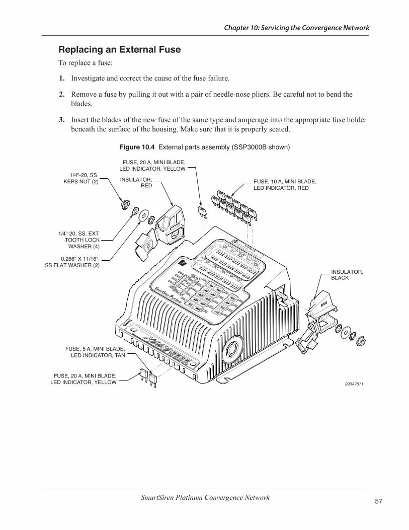
Chapter 10: Servicing the Convergence Network
SmartSiren Platinum Convergence Network 57
Replacing an External FuseTo replace a fuse:
1. Investigate and correct the cause of the fuse failure.
2. Remove a fuse by pulling it out with a pair of needle-nose pliers. Be careful not to bend the blades.
3. Insert the blades of the new fuse of the same type and amperage into the appropriate fuse holder beneath the surface of the housing. Make sure that it is properly seated.
Figure 10.4 External parts assembly (SSP3000B shown)
1 / 2
3 / 4
Produces loud sounds
5 / 6
7 / 8
9 / 10
WARNING
*May cause hearing damage
*Wear hearing protection*See instructions or call
1-800-433-9132
10A AUX
11
12
13
14
6
7
8
9
10
14
13
12
11
AUX
AUX
AUX
AUX
AUX
AUX
AUX
AUX
PWR
ON
RADVOL
PAVOLSIREN
5AHORN
SIREN20A
INPUTINPUTINPUTINPUT
LIGHTBARACTIVE
1
2
3
4
AUX
AUX
PWRPWR
SMSMONRX
TX
AUX
AUX
AUX
AUX
1
2
3
4
5
3
5
AUX
0.266" X 11/16",SS FLAT WASHER (2)
1/4"-20, SS KEPS NUT (2)
INSULATOR,BLACK
INSULATOR,RED
FUSE, 10 A, MINI BLADE, LED INDICATOR, RED
1/4"-20, SS, EXT. TOOTH LOCK
WASHER (4)
FUSE, 20 A, MINI BLADE, LED INDICATOR, YELLOW
FUSE, 5 A, MINI BLADE, LED INDICATOR, TAN
FUSE, 20 A, MINI BLADE, LED INDICATOR, YELLOW 290A7571
20A
SM

Chapter 10: Servicing the Convergence Network
SmartSiren Platinum Convergence Network58
Replacing a Terminal InsulatorTo replace an insulator:
1. Ensure that Keps nuts, the two lock washers, and the two flat washers are removed from the terminal (Figure 10.4 on page 57).
2. Note the locations of the locking tabs in Figure 10.5. Insert a flat-head screwdriver between the housing and the insulator near the front locking tab and pry off the insulator.
Figure 10.5 Locking tabs on red insulator
TX
RX
PWR
ON
RADVOL
PAVOLSIREN
5AHORN
SIREN20A
FRONT LOCKING TAB
PRY HEREREAR LOCKING TAB
SCREWDRIVER
1 / 2
3 / 4
Produces loud sounds
5 / 6
7 / 8
9 / 10
WARNING
*May cause hearing damage
*Wear hearing protection*See instructions or call
1-800-433-9132
10A AUX
11
12
13
14
6
7
8
9
10
14
13
12
11
AUX
AUX
AUX
AUX
AUX
AUX
AUX
AUX
INPUTINPUTINPUTINPUT
LIGHTBARACTIVE
1
2
3
4
AUX
AUX
PWRPWR
SMSMONRX
TX
AUX
AUX
AUX
AUX
1
2
3
4
5
AUX
20A
SM
290A75723. Place the new insulator on the terminal and insert the rear locking tab into the housing.
4. Push the front of the insulator against the housing to lock the front tab.
Reinstalling the Siren Amplifier/Relay ModuleTo reinstall the siren amplifier/relay module in the vehicle (Figure 10.4 on page 57):
1. On the power terminals reinstall a flat washer followed by an external-tooth lock washer.
2. Reconnect the power leads to the terminals and secure them with an external-tooth lock washer and a Keps nut.
3. Reconnect the Convergence Network cable, serial cables, and wiring.
4. Reinstall the siren amplifier/relay module in the vehicle with the installer-supplied #10-32 mounting hardware.

Chapter 10: Servicing the Convergence Network
SmartSiren Platinum Convergence Network 59
Getting Technical Support and ServiceFederal Signal Corporation will service your equipment or provide technical assistance with any problems that cannot be handled locally. Any product returned to Federal Signal for service, inspection, or repair must be accompanied by a Return Material Authorization number. The RMA number can be obtained from your local distributor or Federal Signal. Please provide a brief explanation of the service requested or the nature of the malfunction. Contact your local dealer/distributor for replacement parts availability or contact the Federal Signal Service Department (7 a.m. to 5 p.m., Monday through Friday, Central Time) at:
Service Department Federal Signal Corporation 2645 Federal Signal Drive University Park, IL 60484-3167 800-433-9132 www.fedsig.com
Ordering Replacement PartsThe cover is available as a service part only. To order replacement parts, please contact:
Customer SupportFederal Signal CorporationPhone: 1-800-264-3578
Table 10.1 Replacement parts
Description Part NumberCable Assy., RS485, 25' 1751357-02Cable Assy., Control 17500307Cable Assy., RJ45, Ethernet Crossover 1751532Cable Assy., Auxiliary Relay 1751541SSP3000B Cable Assy., SignalMaster and Inputs 1751542-01SSP2000B Cable Assy. 1751542-NYCable Assy., Control Pad 17500308Cover, SSP3000B 85361196Keypad Legends, Scored Sheet 8572294Fuse, 10 A, Mini Blade 14181-05Fuse, 20 A, Mini Blade 14110-08Fuse, 5 A, Mini Blade, LED Indicator 148210-04Fuse, 10 A, Mini Blade, LED Indicator 148210-06Fuse, 20 A, Mini Blade, LED Indicator 148210-08Slide Switch Assy., Control Pad 122290-01Bezel, Slide Switch 8573060Knob, Aluminum, Slide Switch 85361185Screw, #4-40 x 0.375, Flat Hd., Phil., Slide Switch Bezel 7000259-06
Chapter 10: Servicing the Convergence Network
SmartSiren Platinum Convergence Network60
Returning a Product to Federal SignalBefore returning a product to Federal Signal, call 800-264-3578, 800-433-9132, or 800-824-0254 to obtain a Returned Merchandise Authorization number (RMA number). To expedite the process, please be prepared with the following information:
• Your Federal Signal customer or account number.
• The purchase order number under which the items were purchased.
• The shipping method.
• The model or part number of the product being returned.
• The quantity of products being returned.
• Drop ship information as needed.
• Any estimate required.
When you receive your RMA Number:
• Write the RMA number on the outside of the box of returned items.
• Reference the RMA number on your paperwork inside of the box.
• Write the RMA number down, so that you can easily check on status of the returned equipment.
Send all material with the issued RMA Number to:
Federal Signal Corporation 2645 Federal Signal Drive University Park, IL 60484-3167 Attn: Service Department RMA: #__________

NOTES

NOTES


2645 Federal Signal Drive, University Park, IL 60484-3167Tel.: (800) 264-3578 • Fax: (800) 682-8022www.fedsig.com