Embed Size (px)
Citation preview

Platformă de e-learning și curriculă e-content pentru învățământul superior tehnic
Securizarea Calculatoarelor și a Rețelelor
32. Tehnologia MPLS VPN

MPLS VPN
5-ian-2010

What this lecture is about:
IP CEF
MPLS architecture
What is MPLS?
MPLS labels
Packet forwarding in MPLS
MPLS VPNs
3

IP CEF & MPLS Overview

How does a router forward packets?
Process switching, or routing table-driven switching:
Full lookup is performed at every packet
Slowest method
Fast switching, or cache-driven switching:
Most recent destinations are entered in the cache
First packet is always process-switched
Topology-driven switching:
CEF (prebuilt FIB table) CEFCEF
CEFCEF
Cisco Express Forwarding
5

RIB & FIB
RIB = “Routing Information Base” is basically the routing table.
A routing table often requires multiple lookups in order to determine all required parameters for an outgoing packet.
FIB = “Forwarding Information Base”
It is a pre-built table similar to the routing table.
Provides fast lookup
Does not require recursive loopkups
The FIB is constantly synchronized with the routing table
Works in conjunction with an adjancency table
The AT stores necessary L2 data
Is pre-built to avoid any delays from ARP requests
6

Topologies: router types
With MPLS, we’re talking about ISPs and their customers
Customers are considered sites (companies) with their own private network.
The SP’s role is to ensure connectivity between these sites
C (Customer Router)
Belongs to a customer’s internal network
CE (Customer Edge Router)
Connects to the SP’s network
PE (Provider Edge Router) Connects to customers’ network
P (Provider Router)
Internal SP router
7

Connecting multiple sites – Full mesh
Provides optimal routing between the sites.
Dedicated virtual circuit between any two CE routers.
Very expensive and hard to manage
All VCs musth be manually configured and maintained
8

Connecting multiple sites – Partial mesh
Also known as hub-and-spoke topology.
Central point (of failure).
Suboptimal routing solution.
Less circuits required.
Less expensive.
9

Connecting multiple sites – MPLS topology
Optimal routing solution.
Easy deployment.
Each sites only needs to connect to the SP network.
Connections between CE and PE routers.
Packets are switched (not routed) inside the SP’s network.10
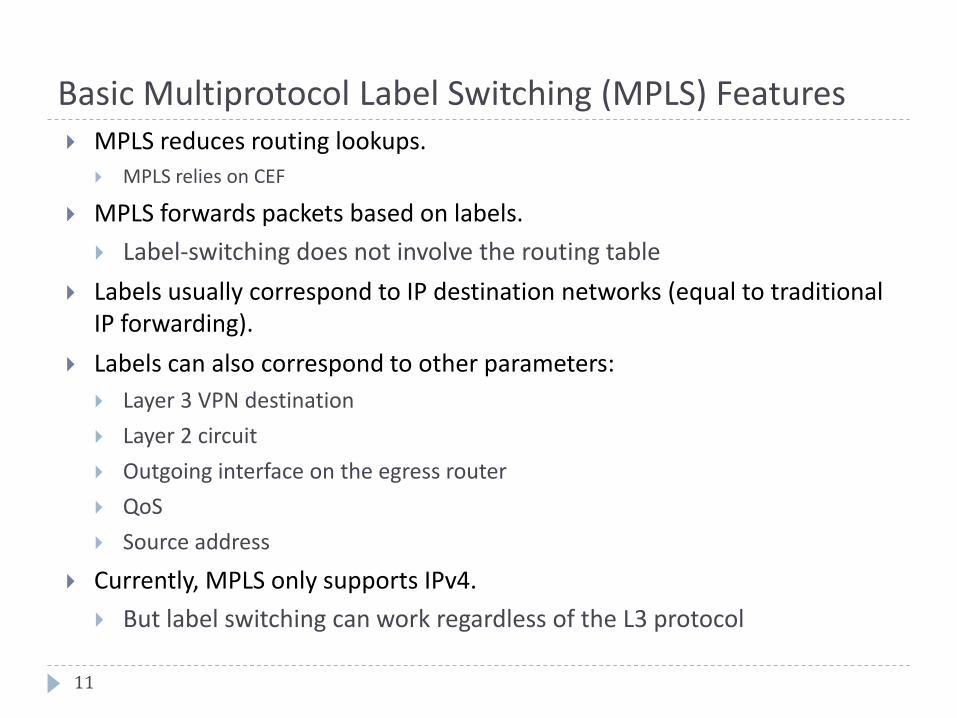
Basic Multiprotocol Label Switching (MPLS) Features MPLS reduces routing lookups.
MPLS relies on CEF
MPLS forwards packets based on labels.
Label-switching does not involve the routing table
Labels usually correspond to IP destination networks (equal to traditional IP forwarding).
Labels can also correspond to other parameters:
Layer 3 VPN destination
Layer 2 circuit
Outgoing interface on the egress router
QoS
Source address
Currently, MPLS only supports IPv4.
But label switching can work regardless of the L3 protocol
11

MPLS Operation
Only edge routers must perform a routing lookup. Core routers switch packets based on simple label lookups and swap labels.
No recursive lookups required.
How do routers know which label to use? Find out later in this lecture.
Edge-2
Core
Edge-1
10.1.1.1
IP packet
10.1.1.1
IP packet
MPLS
frameMPLS
frame
12

MPLS Switching Overview
R1
Edge LSR
R3 LSRR2 LSR
R6
Edge LSR
Station A Station B
MPLS Domain
R4 LSR R5 LSR
LSR: Label Switching Router
Core LSRs forward only based on label information
Edge LSRs perform routing table lookup and label
When IP packets enter the MPLS domain, the Edge LSR converts IP
packets into MPLS packets by adding a label.
When packets leave the MPLS domain, the Edge LSR converts the packets back from MPLS packets to IP packets by removing the label
13

Edge LSR
MPLSIP
MPLS Switching Overview
L
Label Instructions
Internal
Table
LSR
MPLS MPLS
Edge LSRs can receive an IP packet and insert an MPLS label before forwarding it.
Or:
Edge LSRs can receive a labeled packet and remove the label to forward it as an IP packet.
Core LSRs only analyse the MPLS label to decide:
which next hop should be used;
which MPLS label should be used with this next hop.
14

MPLS Characteristics
MPLS technology is intended to be used anywhere, regardless of Layer 1 media and Layer 2 protocol.
MPLS uses a 32-bit MPLS field that is inserted between Layer 2 and Layer 3 headers (frame mode MPLS).
The Ethertype field announces the MPLS label: 0x8847
Which Ethertype field value announces an IP header?
MPLS has two modes:
Frame-mode MPLS (inserts a label between L2 and L3)
Cell-mode MPLS (uses the ATM header as label)
ATM cannot simply insert a field because it is limited to its 53-byte cell size.
MPLS uses an LFIB (Label FIB) to map labels to next-hop addresses.
15

Major Components of MPLS Architecture
Control plane:
Exchanges routing information and labels
Contains complex mechanisms, such as OSPF, EIGRP, IS-IS, and BGP, to exchange routing information
Exchanges labels using protocols like TDP and LDP
Data plane:
Forwards packets based on labels
Has a simple forwarding engine
Uses an LFIB (Label Forwarding Information Base)
16

Control Plane Components Example
A Layer3 routing protocol is required to propagate routing information.
A label exchange mechanism is required to propagate labels for all Layer 3 destinations.
Information from control plane is sent to the data plane.
OSPF: 10.0.0.0/8
LDP: 10.0.0.0/8Label 24
OSPF: 10.0.0.0/8
LDP: 10.0.0.0/8Label 17
Labeled packetLabel 24
Labeled packetLabel 17
Control plane
OSPF
LDP
Data plane
LFIB24 -> 17
17

Control Plane Components Example
Example:
A routing protocol (OSPF) receives and forwards a routing update for the 10.0.0.0/8 network.
A label distribution protocol (LDP) receives label 17 to use for the 10.0.0.0/8 network.
It generates a local label of 24
It sends the 24 label to all upstream neighbors
The upstream neighbors will now use label 24 for all packets destined to 10.0.0.0/8
OSPF: 10.0.0.0/8
LDP: 10.0.0.0/8Label 24
OSPF: 10.0.0.0/8
LDP: 10.0.0.0/8Label 17
Labeled packetLabel 24
Labeled packetLabel 17
Control plane
OSPF
LDP
Data plane
LFIB24 -> 17
18

LFIB example
The LFIB stores one local and one remote label per prefix.
The local label is announced to neighbors that might send packets to the prefix.
The remote label is used when the router itself forwards packets towards the prefix.
Example:Router#show mpls forwarding-table
Local Outgoing Prefix Bytes tag Outgoing Next Hop
tag tag or VC or Tunnel Id switched interface
16 Pop tag 10.1.1.12/30 636 Se3/0 point2point
17 Pop tag 10.10.10.1/32 0 Se3/0 point2point
21 Pop tag 10.1.1.16/30 0 Se3/0 point2point
22 16 10.10.10.5/32 0 Se3/0 point2point
23 Pop tag 10.10.10.2/32 0 Se4/0 point2point
An outgoing pop tag indicates that any labeled packet with the “Local” tag will be sent untagged.
19

Functions of LSRs
Component Function
Control plane– Exchanges routing information
– Exchanges labels
Data plane– Forwards packets (LSRs and
Edge LSRs)
20

MPLS Domain
Label Switch Routers (LSRs)
LSR primarily forwards labeled packets (swap labels).
Edge LSRs:
Label IP packets (impose labels) and forward them into the MPLS domain.
Remove labels (pop labels) and forward IP packets out of the MPLS domain.
Labels are locally significant only.
Multiple interfaces and multiple routers cand share the same labels.
But not multiple destinations on the same router.21
10.1.1.1 L=21 L=25 10.1.1.1
20.1.1.1L=43L=3120.1.1.1
Edge LSR Edge LSRLSR

Component Architecture of Edge LSR
Scenarios:
Receive IP packet > send IP packet (when?)
Receive IP packet > send labeled packet
22
Edge LSR
Control plane
Data plane
Routing protocol
IP routing table
LDP
IP FIB
LFIB
Exchange of
routing information
Exchange of
labels
Incoming IP packets
Incoming
labeled packets
Outgoing IP packets
Outgoing
labeled packets

Component Architecture of Edge LSR
Scenarios:
Receive labeled packet > swap label and send labeled packet
Receive labeled packet > remove label and send IP packet
23
Edge LSR
Control plane
Data plane
Routing protocol
IP routing table
LDP
IP FIB
LFIB
Exchange of
routing information
Exchange of
labels
Incoming IP packets
Incoming
labeled packets
Outgoing IP packets
Outgoing
labeled packets

Component Architecture of Edge LSR
Possible error scenarios:
Receive labeled packet > drop packet because destination is not in LFIB
Receive IP packet > drop packbet because destination is not in FIB
24
Edge LSR
Control plane
Data plane
Routing protocol
IP routing table
LDP
IP FIB
LFIB
Exchange of
routing information
Exchange of
labels
Incoming IP packets
Incoming
labeled packets
Outgoing IP packets
Outgoing
labeled packets

MPLS Labels

Label Format
Field Description
20-bit label The actual label. Values 0 to 15 are reserved.
3-bit experimental (EXP) fieldUsed by Cisco to define a class of service (CoS) in order to assign a value for QoS.
1-bit bottom-of-stack indicator
MPLS allows multiple labels to be inserted. The bottom-of-stack bit determines if this label is the last label in the packet. If this bit is set (1), the setting indicates that this label is the last label.
8-bit Time to Live (TTL) field Has the same purpose as the TTL field in the IP header.
26
Label Exp S TTL
0 19 20 22 23 24 31

Frame Mode MPLS Operation
An MPLS label is announced by the frame’s Ethertype field.
An MPLS label does not store the encapsulated protocol
How does an edge LSR that removes the last label what protocol lies inside?
27
Frame header IP header
Label
Payload
Frame header IP header Payload
Layer 2 Layer 2.5 Layer 3
Routing lookup
and label assignment

Label Stack
There may be more than one label in an MPLS packet.
Only the outermost label is used to route/switch packets in the MPLS domain.
The bottom-of-stack bit indicates whether the next header is another label or a Layer 3 header.
Other labels allow services like:
MPLS VPNs
Traffic engineering (TE)
28
TopFrame header IP header PayloadMiddle Bottom
PID = MPLS-IP S=0 S=0 S=1

Label Allocation in a Frame Mode MPLS Environment
Label allocation and distribution in a frame mode MPLS network follows these steps:
1. IP routing protocols build the IP routing table.
2. Each LSR independently assigns a label to every destination in the IP routing table.
3. LSRs announce their assigned labels to all other LSRs.
4. Every LSR builds LIB, LFIB, and FIB data structures based on the received labels.
Note: Label allocation, label imposing, label swapping, and label popping usually happen in the service provider network, not the customer (enterprise) network. Customer routers never see a label.
29

1. Building the IP routing table
IP routing protocols are used to build IP routing tables on all LSRs.
FIBs are built based on IP routing tables, with no labeling information.
30
Network Next Hop
X B
Network Next Hop
X C
Network Next Hop
X D
Network Next Hop
X C
Network Next Hop Label
X B -
Routing table on A Routing table on B Routing table on C
A B C D
E
FIB on A Routing table on ENetwork X

Allocating labels
Every LSR allocates a label for every destination in the IP routing table.
Labels have local significance.
Label allocations are asynchronous.
Regardless of other routers
31
Network Next Hop
X C
Routing table on B
A B C D
E
Network X
Router B assigns
label 25 to destination X

LIB and LFIB Setup
LIB and LFIB structures have to be initialized on the LSR that is allocating the label.
Untagged action removes the label from the frame and causes the router to send a pure IP packet.
32
Network Next Hop
X C
Network LSR Label
X Local 25
Label Action Next Hop
25 untagged C
Routing table on B LIB on B LFIB on B
A B C D
E
Network X
Router B assigns
label 25 to destination XLocal label is
stored in LIB
Outgoing action has no label
assigned because B has not
received a label for X from C.
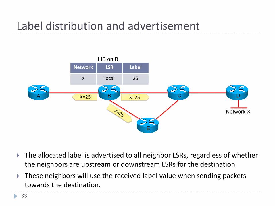
Label distribution and advertisement
The allocated label is advertised to all neighbor LSRs, regardless of whether the neighbors are upstream or downstream LSRs for the destination.
These neighbors will use the received label value when sending packets towards the destination.
33
Network LSR Label
X local 25
LIB on B
A B C D
E
Network X
X=25X=25

Receiving Label Advertisement
Every LSR stores the received label in the LSR’s LIB (Label Information Base).
Edge LSRs that receive the label from their next hop also store the label information in the FIB.
34
Network LSR Label
X local 25
LIB on A
A B C D
E
Network X
X=25X=25
Network Next Hop
Label
X B 25
FIB on A

Interim packet propagation
Forwarded IP packets are labeled only on the path segments where the labels have already been assigned.
If a label has not been received yet from the downstream neighbor, the packet is sent untagged.
35
Label Action Next Hop
25 untagged C
LFIB on B
A B C D
E
Network X
Network Next Hop
Label
X B 25
FIB on A
IP: X1
IP lookup performed in FIB
Packet is labeled.2
Label: 253 IP: X5
Label lookup performed in LFIB.
Label is switched or removed.4

Further label allocation
Every LSR will eventually assign a label for every destination.
A path of MPLS-enabled routers between two PE routers that has propagated all necessary routes and labels is called an LSP (Label Switched Path).
36
Network LSR Label
XB 25
local 47
LIB on C
A B C D
E
Network X
X=47X=47
Label Action NextHop
47 pop D
LFIB on C
Router C assigns
Label 47 to destination X

MPLS VPN

Virtual networks
VPNs
VPN Taxonomy
There are two types of VPN topologies
Overlay VPNs: the SP provides virtual point-to-point links
Customers send their routes through their own tunnels.
Peer-to-peer VPNs: the SP participates in customer routing
The SP is aware and transports the customers’ routes.38
Virtual dial-up networks VLANs
Overlay VPNs Peer-to-peer VPNs
Layer 2 VPNs Layer 3 VPNs ACLs (shared router)
Split routing (dedicated router)
MPLS VPN
X.25
Frame relay
ATM
GRE
IPsec

Overlay VPNs
Layer 1 Overlay VPN
Mentioned for historical reasons only (ISDN, E1/T1)
Layer 2 Overlay VPNTraditional switched WAN
Implmented with X.25, Frame Relay, ATM.
SP is responsible for transport of Layer 2 frames
Customer is responsible for all higher layers
Layer 3 Overlay VPN
SP network is invisible to customer routers
Uses IP tunneling: GRE or IPsec (or both)
Routing protocols run directly between customer routers
SP provides point-to-point data transport between customer sites
The SP is not aware of customer routes.
39

Layer 3 Overlay VPNs
The service provider infrastructure appears as point-to-point links to customer routes.
Routing protocols run directly between customer routers. Adjacencies are established over the SP network
The use of tunnels allows the use of private addresses (RFC 1918). Interconnecting sites with private addressing can be done without NAT
40
Router A
Router B Router C Router D

Peer-to-peer VPNs
The SP and the customers use the same network protocol (IPv4, for example).
The SP’s core carries all customer routes
PE routers exchange routing information with CE routers
CE routers establish L3 adjacencies only with the PE routers
This greately reduces the overhead of full or partial mesh topologies
PE routers exchange routing information required for sites to communicate.
The SP has to run a routing protocol capable of carrying customer routes.
The SP’s network is a public address space
But it carries customer routes that are very likely to use private addressing: first problem.
41

Service provider’s network
Customer siteRouter D
Customer siteRouter C
Customer siteRouter B
Customer siteRouter A
Peer-to-peer VPNs
42
PE router
PE router
PE router
PE router
Routing information is
exchanged between CE
and PE routers.
PE routers exchange
customer routes through
the core network. The customer routes are
sent to other CE routers.

Benefits and disadvantages of the Overlay VPN Implementation Model
Benefits:
Well-known and easy to implement.
Service provider does not participate in customer routing.
Customer network and service provider network are well-isolated.
Disadvantages:
Implementing optimum routing requires a full mesh of VCs.
VCs have to be configured manually.
Bandwidth must be reserved on a site-to-site basis.
Overlay VPNs always increase encapsulation overhead (IPsec or GRE).
24 to 80+ bytes per packet
43

Benefits and Disadvantages of the Peer-to-Peer VPN Implementation Model
Benefits:
Guarantees optimum routing between customer sites.
Extremely scalable
Only sites are configured, not links between them.
Disadvantages:
The service provider participates in customer routing.
The service provider becomes responsible for customer convergence.
PE routers carry all routes from all customers.
The service provider needs detailed IP routing knowledge.And skilled employees.
44
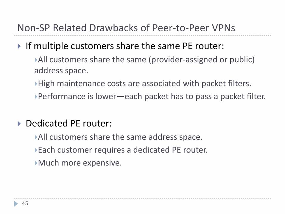
Non-SP Related Drawbacks of Peer-to-Peer VPNs
If multiple customers share the same PE router:
All customers share the same (provider-assigned or public) address space.
High maintenance costs are associated with packet filters.
Performance is lower—each packet has to pass a packet filter.
Dedicated PE router:
All customers share the same address space.
Each customer requires a dedicated PE router.
Much more expensive.
45

MPLS VPN Architecture
An MPLS VPN combines the best features of overlay VPN and a peer-to-peer VPN models:
PE routers participate in customer routing, guaranteeing optimum routing between sites.
Very scalabe with regards to the number of customers.
PE routers carry a separate set of routes for each customer (similar to the dedicated PE router approach).
Customers can use overlapping addresses.
Unique prefixes are added to each IPv4 route to distinguish between different customers that use the same private addressing scheme
46

Service provider’s network
Customer A Site 1
Sample MPLS VPN architecture
PE routers transport customer routes P routers simply provide fast transport, without routing knowledge
47
PE router PE routerP routerCustomer A Site 2
Customer A Site 3
Customer B Site 1
Customer A
Site 4
Customer A
Site 2
Customer B
Site 3
Customer B
Site 4

Inside a PE router
Virtual router for customer B
Virtual router for GlobalVirtual router for customer A
PE router architecture in MPLS VPN
A PE router is internally divided into multiple virtual routers Each virtual router connects one customer
Each customer is assigned an independent Virtual Routing and Forwarding (VRF) table
Each VRF corresponds to a dedicated PE router in the traditional peer-to-peer model
48
Customer A Site 2
Customer A Site 3
Customer A Site 1

Propagation of Routing Information Across the P-Network
The number of customer routes can be very large; BGP is the only routing protocol that can scale to such a number.
BGP is used to exchange customer routes directly between PE routers.
Only one routing protocol is required for any number of customers
49
PE router PE routerP routerCustomer B
Customer C
Customer D
Customer A
Customer B
Customer
C
Customer
D
Customer A
A dedicated routing protocol is used to
carry customer routes between PE
routers.

Route Distinguishers
The 32-bit RD is prepended to an IPv4 address to make the address globally unique.
The resulting address is a VPNv4 address.
VPNv4 addresses are exchanged between PE routers via BGP.
BGP that supports address families other than IPv4 addresses is called multiprotocol BGP (MPBGP).
Question?How is information about overlapping subnets of two customers propagated via a single routing protocol?
Answer: Extend the customer addresses to make them unique.
50

Using RDs in an MPLS VPN
The RD has no special meaning.
The RD is used only to make potentially overlapping IPv4 addresses globally unique.
This design cannot support all topologies that are required by the customer.
51

P-network
VoIP Service on an MPLS VPN
Requirements:
All sites of one customer need to communicate.
Central sites of both customers need to communicate with VoIP gateways and other central sites.
Other sites from different customers do not communicate with each other.
52
PE router PE router
P routerCustomer B
Customer C
Customer D
Customer A
Customer
C
Customer
D
Customer A
VoIP gateway VoIP gateway

Connectivity Requirements for VoIP Service
53
VoIP VPNCustomer A
Customer B
VoIP gateway
VoIP gateway
Central site A Site A-1 Site A-2
Central site B Site B-1 Site B-2

Route Targets
Some sites participate in more than one VPN.
For example the VoIP VPN and the inter-site VPN
The RD only identifies routes from the same customer
But if the customer participates in more than one VPN, all its routes will have the same RD.
RTs were introduced in the MPLS VPN architecture to support complex VPN topologies.
RTs are additional attributes that attach to VPNv4 BGP routes to indicate VPN membership.
VPN 3
VPN 2
VPN 1
Site 4Site 2
Site 5
Site 3
Site 1
54

How Do RTs Work?
Export RTs:
Identify VPN membership
Append to the customer route when the route is converted into a VPNv4 route
Configured separately for each VRF instance.
Import RTs:
Associate with each virtual routing table
Select which routes are inserted into the virtual routing table
55

MPLS VPN Routing Criteria
Designers imposed these criteria on MPLS VPNs:
CE routers can only run standard IP routing software.
CE routers have no MPLS knowledge
CE routers have no VPN knowledge
Only PE routers need to support MPLS VPN services and Internet routing.
P routers have no VPN routes.
56

MPLS VPNBackbone
MPLS VPN Routing: CE Router Perspective
The CE routers run standard IP routing software and exchange routing updates with the PE router.
The PE router appears as another router in the C-network.
57
PE router
CE router
CE router
PE-CE Routing Protocols
PE-CE routing protocols are configured for individual VRFs.
Supported protocols include BGP, OSPF, static, RIP, and EIGRP.
Routing configuration on the CE router has no VRF information.
Customer configuration is the same as if the customer is routing between devices in the C-network.
58

MPLS VPNBackbone
MPLS VPN Routing: P Router Perspective
P routers perform as follows:
Do not participate in MPLS VPN routing and do not carry VPN routes
Run backbone IGP with the PE routers and exchange information about global subnetworks
Use MPLS labels to quickly forwards labeled packets
PE router PE routerP router

MPLS VPN Backbone
MPLS VPN Routing: PE Router Perspective
PE routers exchange the following:
VPN routes with CE routers via per-VPN routing protocols
Core routes with P routers and PE routers via core IGP
VPNv4 routes with other PE routers via MPBGP sessions
60
PE router PE routerP router
CE router
CE router
CE router
CE router
MP-BGP
VPN routingVPN routing
Core IGP Core IGP

End-to-End Routing Information Flow
61
MPLS VPN Backbone
PE router PE routerP router
CE router
CE router
CE router
CE router
IPv4 update MPBGP update IPv4 update
PE routers receive IPv4 routing
updates from CE routers and install
them in the appropriate VRF table
1
PE routers export VPN routes from VRF
tables into MPBGP and propagate them
as VPNv4 routes to other PE routers 2
The receiving PE router imports the incoming
VPNv4 routes into the appropriate VRF table
based on RD, RT and import values.3
The routes installed in the VRF tables are
propagated to the CE routers.4

VPN PHP
62
MPLS VPN Backbone
Ingress
PE router
Egress
PE routerP router
CE router
CE router
CE router
CE router
PHP = Penultimate Hop Popping (try saying that 3 times fast!)
The last PE router receives a labeled packet and sends an IP packet
It performs a label lookup (LFIB) and a routing lookup (FIB)
The last P router can decide to remove the label before seding the packet to the last PE router.
Now, the last PE router only performs a FIB lookup
IP
IP VPN L2IP VPN L1 IP VPN
P routerIP

Penultimate Hop Popping (PHP)
PHP optimizes MPLS performance by reducing CPU effort on Edge LSRs.
The Edge LSR advertises a pop or implicit null label (value of 3) to a neighbor.
The pop tells the neighbor to use PHP.
63