Embed Size (px)
Citation preview

Plant controller for electric monorail
systems
___________________
___________________
___________________
___________________
___________________
___________________
___________________
___________________
___________________
___________________
___________________
SIMATIC
EMS400S Plant controller for electric monorail systems
System Manual
09/2013 A5E03474151-03
Preface
Product overview 1
EMS400S system description
2
Safety instructions 3
Connecting and routing cables
4
Commissioning the controller 5
Carrier controller in the various operating modes
6
Diagnostics 7
Maintenance and repairs 8
Technical specifications 9
Appendix A

Siemens AG Industry Sector Postfach 48 48 90026 NÜRNBERG GERMANY
A5E03474151-03 Ⓟ 09/2013 Technical data subject to change
Copyright © Siemens AG 2013. All rights reserved
Legal information Warning notice system
This manual contains notices you have to observe in order to ensure your personal safety, as well as to prevent damage to property. The notices referring to your personal safety are highlighted in the manual by a safety alert symbol, notices referring only to property damage have no safety alert symbol. These notices shown below are graded according to the degree of danger.
DANGER indicates that death or severe personal injury will result if proper precautions are not taken.
WARNING indicates that death or severe personal injury may result if proper precautions are not taken.
CAUTION indicates that minor personal injury can result if proper precautions are not taken.
NOTICE indicates that property damage can result if proper precautions are not taken.
If more than one degree of danger is present, the warning notice representing the highest degree of danger will be used. A notice warning of injury to persons with a safety alert symbol may also include a warning relating to property damage.
Qualified Personnel The product/system described in this documentation may be operated only by personnel qualified for the specific task in accordance with the relevant documentation, in particular its warning notices and safety instructions. Qualified personnel are those who, based on their training and experience, are capable of identifying risks and avoiding potential hazards when working with these products/systems.
Proper use of Siemens products Note the following:
WARNING Siemens products may only be used for the applications described in the catalog and in the relevant technical documentation. If products and components from other manufacturers are used, these must be recommended or approved by Siemens. Proper transport, storage, installation, assembly, commissioning, operation and maintenance are required to ensure that the products operate safely and without any problems. The permissible ambient conditions must be complied with. The information in the relevant documentation must be observed.
Trademarks All names identified by ® are registered trademarks of Siemens AG. The remaining trademarks in this publication may be trademarks whose use by third parties for their own purposes could violate the rights of the owner.
Disclaimer of Liability We have reviewed the contents of this publication to ensure consistency with the hardware and software described. Since variance cannot be precluded entirely, we cannot guarantee full consistency. However, the information in this publication is reviewed regularly and any necessary corrections are included in subsequent editions.

Plant controller for electric monorail systems System Manual, 09/2013, A5E03474151-03 3
Preface
Purpose This document offers an overview of the SIMATIC EMS400S plant controller for electrical monorail systems.
Note
Read this system manual to understand the safety concept, functional principle and basics of configuration and commissioning.
This document is intended for:
● System planners
● Programmer
● Commissioning engineers
● Operators
● Maintenance personnel
Pay particular attention to section "Safety instructions (Page 35)".
Scope of documentation The documentation for the SIMATIC EMS400S plant controller is organized as follows:
● System documents
● Supplementary documents

Preface
Plant controller for electric monorail systems 4 System Manual, 09/2013, A5E03474151-03
System documents
The following documents provide a full description of the "EMS400S Plant controller for Electrical Monorail Systems":
The documents in the figure are available at:
EMS400S product documentation (http://support.automation.siemens.com/WW/view/en/68156412/133300)
The documents contain links to other relevant documents for Siemens standard modules that are used for the EMS. The "S7-1200 Automation System" System Manual for the SIMATIC-S7 CPU is of ultimate importance in this context.
Supplementary documents
Additional information in connection with the EMS400S plant controller is available in the following documents:
● System description of the EMS400S test system in Altenfurt near Nuremberg
● Application example "EMS400S test system in Altenfurt near Nuremberg"
The application example is suitable for commissioning. It includes basic control functions with at least one run command. It also addresses the frequency converter.
● "Communication plant segment controller – Carrier Controller" Application Manual
● "EMS400S Carrier Controller" circuit diagrams
● Product information
● Data sheets
● Dimensional drawings and 3D models
● Approvals

Preface
Plant controller for electric monorail systems System Manual, 09/2013, A5E03474151-03 5
Scope of validity This documents applies to:
An electrical monorail system, which is equipped with a SIMATIC EMS400S plant controller.
This document applies under the following conditions:
● The EMS suspension structure is installed and technically accepted for the system
● The EMS carriers are installed on the EMS and technically accepted for the system
This includes installation of the necessary sensors.
● All necessary safety equipment is installed and accepted for the system
This includes the emergency-off switches and their integration in the system circuitry.
● All controllers are connected.
EMS engineering signs responsible for engineering and installing the plant controller and the plant segment controllers.
● The power supply to the system is installed in accordance with regulations
This includes the connection of the contact conductors of the rail system to the power supply system and the connection of the line to the current collectors.
Note
Observe the following points: • You are also going to need this document whenever the system is recommissioned. Keep
this supplementary documentation in a safe place for the entire life cycle of the device. • Submit all of these documents to a future owner of the device.
Knowledge required General knowledge in the fields of electrical engineering, automation technology and process communication is prerequisite for comprehension of this documentation. This includes knowledge of the "TIA Portal" engineering software.

Preface
Plant controller for electric monorail systems 6 System Manual, 09/2013, A5E03474151-03
Style conventions Style Convention Scope "Add screen" • Terminology for the user interface, e.g. dialog name, tab,
button, menu command • Necessary entries, e.g. limit value, tag value • Path information
"File > Edit" Operational sequences, e.g, menu command, shortcut menu command
You should also observe notes that are marked as follows:
Note
A note contains important information about the product described in the document and its handling, or a specific section of the document to which you should pay particular attention.
Naming conventions Term Applies to CPU • S7-1200 CPU
Controller • EMS plant control system • Plant controller • Carrier controller
Control cabinet • Installation cabinet • Enclosure • Terminal box • Console • Switchboard
Figures This document contains illustrations of the described devices. The illustrations may deviate from the particularities of the delivered device.

Plant controller for electric monorail systems System Manual, 09/2013, A5E03474151-03 7
Table of contents
Preface ................................................................................................................................................... 3
1 Product overview .................................................................................................................................... 9
2 EMS400S system description ................................................................................................................ 11
2.1 System configuration ................................................................................................................... 11 2.1.1 Basic system structure ................................................................................................................. 11 2.1.2 System example........................................................................................................................... 14 2.1.3 Programming ................................................................................................................................ 17 2.1.4 Expansion options ........................................................................................................................ 18 2.1.5 EMS400S accessories ................................................................................................................. 18
2.2 System components .................................................................................................................... 19 2.2.1 Relevant stationary components of the EMS plant ...................................................................... 19 2.2.2 Plant segment controller .............................................................................................................. 20 2.2.2.1 Central installation of the plant segment controllers .................................................................... 21 2.2.2.2 Distributed installation of the segment controllers ....................................................................... 22 2.2.3 Mobile components of the plant controller ................................................................................... 23 2.2.4 EMS rail – EMS carrier interface .................................................................................................. 25 2.2.5 Communication at the plant segment transitions ......................................................................... 27
2.3 Function description and communication .................................................................................... 32 2.3.1 Synchronization signal ................................................................................................................. 32 2.3.2 Method for activation of the plant segments ................................................................................ 32 2.3.3 Description of the transmission channel ...................................................................................... 33 2.3.4 Communication fault on RAIL ...................................................................................................... 33
3 Safety instructions ................................................................................................................................. 35
3.1 Personal safety ............................................................................................................................ 35 3.1.1 Occupational safety regulations ................................................................................................... 37 3.1.2 Safety precautions for RAIL contact conductors (rails)................................................................ 38 3.1.3 Overvoltage protection for RAIL contact conductors ................................................................... 39
3.2 Obligations and liability ................................................................................................................ 44 3.2.1 About this document .................................................................................................................... 44 3.2.2 Risks in the handling of EMS carriers .......................................................................................... 44
3.3 IT security notes ........................................................................................................................... 44
4 Connecting and routing cables .............................................................................................................. 45
4.1 Wiring the EMS400S carrier controller ........................................................................................ 45
4.2 Wiring data cables to the plant segment controller ...................................................................... 46
4.3 Wiring the EMERGENCY OFF circuitry of the EHB plant............................................................ 47
4.4 Cable routing ................................................................................................................................ 48

Product overview
Plant controller for electric monorail systems 8 System Manual, 09/2013, A5E03474151-03
5 Commissioning the controller ................................................................................................................ 49
5.1 Transmitting information via RAIL ............................................................................................... 49
5.2 Parameterizing the frequency inverter ........................................................................................ 49
5.3 Initial commissioning ................................................................................................................... 50
6 Carrier controller in the various operating modes ................................................................................... 51
6.1 Operating modes ......................................................................................................................... 51
6.2 Setup mode by means of IR remote control ............................................................................... 51
6.3 Automatic mode .......................................................................................................................... 54
6.4 Messages on the display unit ...................................................................................................... 54
7 Diagnostics ........................................................................................................................................... 55
7.1 Segment/carrier controller diagnostics ........................................................................................ 55
7.2 Diagnostics by means of diagnostics unit ................................................................................... 55
7.3 System diagnostics ..................................................................................................................... 55
8 Maintenance and repairs ....................................................................................................................... 57
9 Technical specifications ........................................................................................................................ 59
9.1 Technical specifications of the EMS400S system ...................................................................... 59
9.2 Technical specifications of the EMS components with EMS400S .............................................. 60 9.2.1 Clock generator for communication synchronization .................................................................. 60 9.2.2 Technical specifications of the contact conductors (rails) ........................................................... 60 9.2.3 Technical specifications of the EMS400S plant controller .......................................................... 61 9.2.4 PSB-S module and EMS carrier.................................................................................................. 61 9.2.5 Communication via rails .............................................................................................................. 62
9.3 Technical specifications of the EMS400S carrier controller ........................................................ 62
9.4 Technical specifications of the EMS400S diagnostics unit ......................................................... 62
9.5 Wiring diagrams .......................................................................................................................... 62 9.5.1 48 V DC supply wiring diagram ................................................................................................... 62 9.5.2 400/500 V AC supply wiring diagram .......................................................................................... 64 9.5.3 SYNC connection wiring diagram ............................................................................................... 65 9.5.4 Segment transition wiring diagram .............................................................................................. 66
9.6 Standards on operating safety .................................................................................................... 66
9.7 Environmental conditions ............................................................................................................ 66
A Appendix .............................................................................................................................................. 67
A.1 Technical support ........................................................................................................................ 67
A.2 Abbreviations .............................................................................................................................. 68
Glossary ............................................................................................................................................... 69

Product overview
Plant controller for electric monorail systems System Manual, 09/2013, A5E03474151-03 9
Product overview 1
Automatic conveying systems are used throughout the steel industry and logistics sector. The automotive industry is a major user of internal logistics applications. The EMS400S plant controller is designed for load conveyance in EMS. Drive power can be adjusted by means of an optional external braking resistor.
The EMS400S plant controller comprises the following components:
The PSB-S module forms the plant segment controller in combination with an S7-1200 CPU. One of its specific functions is the implementation of the data sent by PROFINET and its infeed to the RAIL contact conductors. The communication connection with the EMS400S carrier controller is established by means of the contact conductors.
A PSB-C module is integrated in the EMS400S carrier controller that belongs to the mobile system component. In combination with an S7-1200 CPU, the PSB-C module handles control tasks that are relevant to the EMS carrier. The PSB-S and PSB-C modules communicate by means of clocked 16-bit data subframes. The data content can be programmed in the TIA Portal to suit requirements.
Note PSB-C modules and SIMATIC S7
Because the carrier controller has an internal 24 V DC power supply, the PSB C modules can only be combined with DC CPU, for example, with SIMATIC S7 1212 DC/DC/DC, S7 1214 DC/DC/DC, etc.
Product overview
Plant controller for electric monorail systems 10 System Manual, 09/2013, A5E03474151-03
The EMS carrier can be operated in commissioning mode by means of remote control.
The EMS carrier is a conveying appliance for transporting objects such as car doors or cockpits. The EMS carrier can be operated at variable velocity on the working and parking tracks. The respective velocity is set by the plant segment controller.
You use the EMS400S diagnostics unit to check the proper communication between plant segment controller and carrier controller.
Thanks to the EMS400S plant controllers, users benefit from gains in terms of the flexibility and universality of the EMS and electric conveyor systems. The components mentioned enable the independent control of several EMS carriers on the plant segment using only a single data bus.
The EMS with EMS400S plant controller is suitable for operation in the following sectors:
● Automotive industry
● Mechanical engineering
● Chemical industry
● Trading
● Logistics
The EMS400S plant controller can be used in the following business segments:
● Incoming and outgoing goods
● Warehouse
● Order picking
● Dispatch
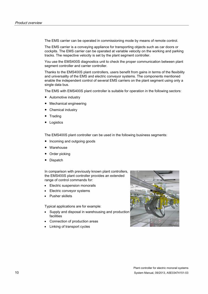
In comparison with previously known plant controllers, the EMS400S plant controller provides an extended range of control commands for: • Electric suspension monorails • Electric conveyor systems • Pusher skillets Typical applications are for example: • Supply and disposal in warehousing and production
facilities • Connection of production areas • Linking of transport cycles

Plant controller for electric monorail systems System Manual, 09/2013, A5E03474151-03 11
EMS400S system description 2 2.1 System configuration
2.1.1 Basic system structure
Schematic structure The EMS superstructure carries straight and bent EMS rails that form the rail system. The rail system usually also integrates bypass sections, ascending EMS rail sections as well as hoisting and processing stations.

EMS400S system description 2.1 System configuration
Plant controller for electric monorail systems 12 System Manual, 09/2013, A5E03474151-03
The following figure shows a diagram of a simplified rail system with three EMS carriers. It shows the different process control and control levels, with control levels 2 and 3 comprising the actual EMS400S plant controller.

EMS400S system description 2.1 System configuration
Plant controller for electric monorail systems System Manual, 09/2013, A5E03474151-03 13
Process control level
The material flow on the EMS is controlled at process control level. The process control computer at the process control level communicates with the plant controller assigned to control level 1 via PROFINET.
Control levels
The plant controller is organized as follows:
● Control level 1 – Plant controller of the EMS
You may use a SIMATIC S7-300 controller to control the system. The control level communicates with the plant segment controller via PROFINET.
● Control level 2 – Plant segment controller
The plant segment controller is formed by the S7-1200 CPU that is linked to one or several PSB-S modules. The plant segment controller transmits data to the segments by means of the communication rails (RAIL) which influences all EMS carriers with EMS400S controller by means of the rail communication.
● Control level 3 – EMS400S carrier controller
The carrier controller consists of an S7-1200 CPU and a PSB-C module. The EMS400S carrier controller is an integral component of the EMS carriers. The freely programmable carrier controller program runs in the S7-1200 CPU.
A plant controller is not necessary for communication between the plant segment controller and carrier controller.
Communication The EMS controller is linked with the process control level and the plant segment controllers of control level 2 via PROFINET. It is necessary to implement a digital signal conversion system for transferring the data transmitted in the plant segment controllers to the mobile EMS carriers. This signal conversion is handled by the PSB modules. Data is exchanged between the PSB-S and PSB-C modules by means of clocked data subframes that are transmitted via the communication rails (RAIL) and the contact conductors on the carrier. Data exchange is plant segment-related and comprises 16 bits per data clock cycle.
The basics of communication are described in the "EMS400S PSB Modules" operating instructions.
You can find additional information in the following document:
"Function Blocks (Page 3)" application manual

EMS400S system description 2.1 System configuration
Plant controller for electric monorail systems 14 System Manual, 09/2013, A5E03474151-03
Synchronization signal The synchronization signal is always required for synchronization of the communication between plant segment controllers.
The synchronization signal is formed with the help of a clock generator of the CPU in a plant segment controller. This signal is transmitted by this CPU to the connected PSB-S modules. The other plant segment controllers also need the synchronization signal of the master CPU for isochronous communication. The synchronization signal must always have a rate of change of 1 μs when connecting the individual plant segment controllers with each other to ensure trouble-free operation.
Additional information is available in the section "Clock generator for communication synchronization (Page 60)".
2.1.2 System example Siemens Corporation has installed an EMS test system near Nuremberg, Germany, for testing and demonstration purposes. Visits and system demos can be arranged on request. The documentation for the test system is available in the System description of the EMS400S test system in Altenfurt near Nuremberg (Page 3).
The system consists of an oval-shaped rail system with one branch. The system has a total length of approximately 45 m and contains the following:
● An ascending section with 30° gradient
● A rail crossing
Contact conductors of Paul Vahle GmbH & Co. KG, 59174 Kamen, Germany, are used for the power supply and communication.
The rail system is divided into 30 plant segments.

EMS400S system description 2.1 System configuration
Plant controller for electric monorail systems System Manual, 09/2013, A5E03474151-03 15

EMS400S system description 2.1 System configuration
Plant controller for electric monorail systems 16 System Manual, 09/2013, A5E03474151-03
A SIMATIC S7-300 controls the EMS. This controller communicates with the connected plant segments via the EMS400S plant segment controllers. The plant segment controllers are installed at a central location. The EMS is equipped with 3 EMS carriers.
Status information is routed from the plant segment controllers to the plant controller and saved to a separate interface data block for each plant segment controller.
The following figure shows a section of the EMS400S test system.

EMS400S system description 2.1 System configuration
Plant controller for electric monorail systems System Manual, 09/2013, A5E03474151-03 17
2.1.3 Programming
Engineering software The EMS400S carrier controller and the EMS400S plant segment controller can be configured using the "TIA Portal" V12 SP1 configuration software. You need the following add-on for engineering in the TIA Portal:
SIMATIC TIA Portal V12 SP1 Add-on
Programming The plant controllers and the carrier controllers include the SIMATIC S7-1200 automation system that is programmed with the help of the STEP 7 programming languages.
Users can write their own STEP 7 automation programs for the plant segment controllers. The transmission of commands and messages to the rail segments as well as the evaluation of segment faults and carrier alarms is specified with the automation programs.
The carrier controller can be adapted to the requirements of the automation concept through free programming. Each carrier function with associated control commands or carrier alarms can be programmed individually.
Function blocks The "EMS400S" function blocks simplify programming of the PSB modules. These function blocks are provided with the add-on mentioned above, which must be installed on the respective configuration computer.
The function blocks are used for easy handling of communication. They reduce the programming required for data exchange between the PSB-S module and the PSB-C module. The function blocks include all major functions required for data exchange.
You can find more information under "Scope of the documentation" in the Preface (Page 3) of the "Function Blocks" application manual.

EMS400S system description 2.1 System configuration
Plant controller for electric monorail systems 18 System Manual, 09/2013, A5E03474151-03
2.1.4 Expansion options You can use SIMATIC products for universal and comprehensive expansion of the system limits of the EMS400S plant controller, for example:
● Digital modules of the SIMATIC S7-1200
● External frequency converter for adapting the drive performance at the EMS carrier
Products relevant for the expansion of the EMS as well as accessories are available in the Siemens product catalog under:
Industry Mall (http://mall.automation.siemens.com)
2.1.5 EMS400S accessories The following accessories can be ordered for the EMS400S:
● IR remote control
The IR remote control communicates by means of the display unit of the EMS400S carrier controller. It supports the operating modes "Automatic mode" and "Setup mode". You can find detailed information in the "EMS400S Display Unit and IR Remote Control" operating instructions.
● External IR sensor
Specific conditions in the EMS may call for an expansion of the reception range of the display unit. You can use the external IR sensor to expand the reception range or to set it up at the necessary location.
● EMS400S diagnostics unit
The EMS400S diagnostics unit is used to check communication via RAIL.
You can use the diagnostics unit to check the physics, the transmission protocol and the transmitted data.
Long-term tests are possible for the EMS400S plant segment controller as well as the EMS400S carrier controller.
You can find detailed information in the "EMS400S Diagnostics Unit" operating instructions.
A link to the documents mentioned above is available in the Preface (Page 3), "Scope of this documentation" section.

EMS400S system description 2.2 System components
Plant controller for electric monorail systems System Manual, 09/2013, A5E03474151-03 19
2.2 System components
2.2.1 Relevant stationary components of the EMS plant The EMS400S plant control system consists of stationary and mobile system components.
The stationary system components relevant to EMS400S include:
● The superstructure
The superstructure carries the rail system.
● The rail system
The rail system consists of interconnected EMS rails. Crossings, lifts as well as ascending and descending sections may be integrated. The contact conductors installed on the EMS rail provide the means for the power supply and communication.
The rail system is interrupted at process-specific positions by means of a rail intersection. The resulting segmentation allows you to assign a specific plant segment to a specific communication channel of the EMS400S segment controller.
● The plant system
The rail system is divided into plant segments by the rail intersection. A rail intersection electrically separates the plant segments, which means the rails with contact conductors RAIL A and RAIL B. Each plant segment is connected to a PSB-S module and therefore to a specific segment controller. This facilitates communication at specific plant segments with the EMS carriers present in a segment.
The power conductor rails are not interrupted by the rail intersections.
● The segment controller
The segment controller is part of control level 2; at least one segment controller is required. It communicates with all EMS400S carrier controllers in the connected plant segments.

EMS400S system description 2.2 System components
Plant controller for electric monorail systems 20 System Manual, 09/2013, A5E03474151-03
2.2.2 Plant segment controller The main modules of the segment controller include:
● A power supply
● An S7-12xx controller
● One to eight PSB-S modules
The PSB-S module serves for communication with the EMS carriers currently present in the assigned plant segment.
● Power and data lines
Note that you need to synchronize the segment controllers in accordance with chapter "Synchronization signal (Page 32)".
The segment controller can be installed as follows:
● Along with the EMS plant controller in a central control cabinet – see chapter "Central installation of the plant segment controllers (Page 21)".
● At distributed locations in the EMS plant – see chapter "Distributed installation of the segment controllers (Page 22)".
The plant is operated by means of an HMI device. The following configuration is a practical example of operation with one or several central segment controllers.
The control level 2 shown in the figure would not exist in the cabinet in a system with distributed segment controllers.

EMS400S system description 2.2 System components
Plant controller for electric monorail systems System Manual, 09/2013, A5E03474151-03 21
2.2.2.1 Central installation of the plant segment controllers The following figure shows a practical example of a centrally installed EMS controller. The EMS controller and the corresponding plant segment controllers are installed in the same control cabinet.
● Advantage of this arrangement
– Low cost for control cabinet installation
– Central maintenance
● Expenditures required
– Longer cable lengths
– Higher costs of power and data lines
– Higher installation expenditure
For information about the cabling, refer to the following section:
Wiring the EMS400S carrier controller (Page 45)

EMS400S system description 2.2 System components
Plant controller for electric monorail systems 22 System Manual, 09/2013, A5E03474151-03
2.2.2.2 Distributed installation of the segment controllers The following figure shows the distributed installation of the segment controllers. Each segment controller is installed in a separate terminal box. The terminal boxes are placed as close as possible to the EMS rail infeed points.
● Advantage of this arrangement
– Short cable lengths between the segment controller and EMS rail
● Expenditures required
– Several terminal boxes
– Distributed installation hinders access
– Distribution of the synchronization signal

EMS400S system description 2.2 System components
Plant controller for electric monorail systems System Manual, 09/2013, A5E03474151-03 23
2.2.3 Mobile components of the plant controller The EMS carrier with the EMS400S carrier controller is part of the mobile components as far as the plant controller is concerned.
The EMS carrier controller handles the control of the drives of the EMS carrier.
The EMS carrier consists of a carrier frame to which all modules that are necessary for fastening and handling the transported goods are mounted. The carrier frame is a conveying facility with inherent drive and roll guide. The carrier frame is installed on joint bearings between two carrier mounts, with the drive unit being installed on one of the carrier mounts. The frame is driven by means of non-profiled rolls.
The following figure shows an example of an EMS carrier:

EMS400S system description 2.2 System components
Plant controller for electric monorail systems 24 System Manual, 09/2013, A5E03474151-03
The main components of the EMS carrier include:
● Carrier frame
The carrier frame represents the carrier module for the EMS carrier. Project management is responsible for the engineering and design of the EMS.
● Drive unit
The drive unit serves for moving the EMS carrier at a variable velocity, controlled braking of the carrier, as well as for retention of the EMS carrier at a work station.
For more information, refer to the EMS documentation.
● Current collector carrier
The current collectors on the current collector carrier serve for the line-bound transmission of power and data.
● EMS400S carrier controller
The carrier controller installed in an enclosure with degree of protection IP65. The carrier controller consists of a S7-1212 CPU and a PSB-C module. Additional components and interfaces, for the braking resistor, for example, are integrated. The carrier controller can be programmed in the TIA Portal.
Note
PSB-C modules and SIMATIC S7
Because the carrier controller has an internal 24 V DC power supply, the PSB C modules can only be combined with DC CPU, for example, with SIMATIC S7 1212 DC/DC/DC, S7 1214 DC/DC/DC, etc.
You can find more information in the "EMS400S Carrier Controller" operating instructions.
An EMS carrier can be moved manually in "Setup mode" in connection with the IR remote control. Setup mode is described in the section "Setup mode with IR remote control (Page 51)". You can find information on the function and operation of the IR remote control in the "EMS400S Display Unit and IR Remote Control" operating instructions.
● Braking resistor
The braking resistor may be required to dissipate the heat that is generated during braking of the EMS carrier. This mainly depends on the system geometry and the system design. The braking resistor mounted to the carrier dissipates the braking energy of the carrier drive converter (MICROMASTER 440) to the environment. The size and installation has to be planned for the system and is the responsibility of the electrical engineer.
● Sensors
The sensors control the position and distance between the EMS carriers as well as other project-specific carrier functions. The evaluation of the sensors is programmed in the TIA Portal by means of the user program. System designers of the EMS are responsible for the selection of sensors and their system-specific installation on the carrier frame.
A link to the documents mentioned above is available in the Preface (Page 3), "Scope of this documentation" section.

EMS400S system description 2.2 System components
Plant controller for electric monorail systems System Manual, 09/2013, A5E03474151-03 25
2.2.4 EMS rail – EMS carrier interface
Current collector carrier The following figure shows a practical example of a collector carrier with 6 collectors for the power supply and communication. A collector consists of two carbon brushes each and is mounted on the collector carrier so that it can move.
The collector carrier is mounted to the EMS carrier. The gaps and positions of the collectors are tuned to the EMS rail.
Compared to the other carbon brushes, the collector for the neutral conductor differs with regard to its width. The wider dimension of the carbon brush of the neutral conductor ensures that it will not make contact if it slips out of the corresponding contact conductor.

EMS400S system description 2.2 System components
Plant controller for electric monorail systems 26 System Manual, 09/2013, A5E03474151-03
EMS rail The EMS rail is a component of the superstructure of the EMS plant. It is a carrier rail that serves to suspend and move the EMS carrier. The contact conductors installed on the EMS rail provide the means for the power supply and communication. The contact conductors are made of an insulated standard U profile that is contacted on its inside by a carbon brush.
The EMS carrier moves on two roll guides that are suspended on the EMS rail. The following figure shows the EMS rail with contact conductors and engaged collectors.
The power and communication signals are routed to the EMS carrier via the contact conductors on the EMS rail. The interconnected EMS rails form the rail system of the EMS plant.

EMS400S system description 2.2 System components
Plant controller for electric monorail systems System Manual, 09/2013, A5E03474151-03 27
2.2.5 Communication at the plant segment transitions The following figure symbolizes the communication on the RAIL contact conductors under optimum conditions. There is no EMS carrier on the plant segment transition.
The operation of the EMS carriers is interrupted as soon as the sliding contactors (current collectors) of an EMS carrier cause a bridging and thus a short circuit on the rail segments (contact conductors RAIL A and B). The communication signals of the two segments are overlaid in this case and can therefore not be clearly interpreted. This communication fault cannot be prevented with this segment design.
The carbon brushes of the current collectors are in contact with the RAIL contact conductors of two neighboring plant segments at the plant segment transition.
This may cause the following to occur:
● The EMS carrier controller of the carrier that has caused the bridging receives commands from two plant segment controllers
● The EMS carrier controller of the carrier that has caused the bridging sends data to two plant segment controllers
● The EMS carrier controller of the carrier that has caused the bridging sends data to two RAIL inputs of a plant segment controller
These situations also occur at plant segment transitions in the following cases:
● The EMS carrier is moving across the plant segment transition
● The EMS carrier has come to a standstill on the plant segment transition

EMS400S system description 2.2 System components
Plant controller for electric monorail systems 28 System Manual, 09/2013, A5E03474151-03
Below find a description of the segment arrangement versions that prevent the fault of the plant segment transition or make it acceptable. Advantages and disadvantages of the different versions are briefly explained.

EMS400S system description 2.2 System components
Plant controller for electric monorail systems System Manual, 09/2013, A5E03474151-03 29
The plant segment controller and the carrier controller respond differently, depending on the design of the plant segment transition. The following versions reflect this state.
● Version 1: Segment short circuit in case of overtravel
The sliding contactors (carbon) of the current collector on the EMS carrier cause a bridging at the plant segment transition.
Advantages and disadvantages:
– Low installation expenditures for the EMS
Rail intersection in this context means that the RAIL contact conductors are separated electrically by the gap.
– No secure communication while the relevant segments are bridged
A software solution can monitor communication for this version of the plant segment transition, see version 4.
● Version 2: Use of insulating segments (insulator)
The sliding contactors (carbon) of the current collector on the EMS carrier move cross a short insulation segment that is as least as long as the two sliding contactors.
Advantages and disadvantages:
– Higher installation costs due to additional insulating segments per segment transition
– No communication on the insulating segment
The EMS carrier cannot be addressed by the plant segment controller once it has reached a standstill on the insulating segment. This situation must be taken into account in the carrier controller program.

EMS400S system description 2.2 System components
Plant controller for electric monorail systems 30 System Manual, 09/2013, A5E03474151-03
● Version 3: Insulating segments with signal bridging (electrically conductive)
The sliding contactors (carbon) of the current collector on the EMS carrier move onto an electrically conductive insulating segment.
The changeover to the RAIL conductor may be handled mechanically or electrically with two initiators for trouble-free transition.
Principle of operation:
– Segment n is connected with the insulating segment by contacts or by a software control in the plant segment controller. Both segments receive the same communication signals.
– The initiator n signals an outbound carrier from segment n.
– The inbound initiator T1 of the insulating segment signals "carrier entering insulating segment".
– When the carrier has left segment n, the insulating segment is switched over with the descending initiator signal to segment n+1.
– The initiator n+1 of the next segment n+1 signals when the carrier has left the insulating segment. The signal of the insulating segment is switched back to the segment n.
Advantages and disadvantages:
– Uninterrupted communication
This version enables addressing of the EMS carrier even if it has stopped on the insulating segment.
– Higher installation expenditures in the EMS due to the changeover of signals between adjacent plant segment controllers.

EMS400S system description 2.2 System components
Plant controller for electric monorail systems System Manual, 09/2013, A5E03474151-03 31
● Version 4: False signal detection at segment transition
The faults of data transmission still exist here. The segment transition can be detected by protocol monitoring in the PSB-C modules and PSB-S modules. The PSB modules control a bridge bit so that the user program itself in the CPU can decide what to do with the data.
In case of prioritized bit commands, the pending information can still be interpreted despite the short circuit.
This version represents a compromise between continuous communication and minimal system installation costs. The carrier can be started up from standstill due to the segment short circuit detection.
Summary
● Version 2 can also be used for less complex EMS. Here the carriers must start up with a slow traversing speed after a voltage failure or when they are switched on.
● We recommend version 3 if continuous communication is required.
● If you do not need continuous communication, version 4 is a low-cost alternative.

EMS400S system description 2.3 Function description and communication
Plant controller for electric monorail systems 32 System Manual, 09/2013, A5E03474151-03
2.3 Function description and communication
2.3.1 Synchronization signal The synchronization signal serves to ensure synchronous data transmission between the EMS400S plant segment controllers and the EMS400S carrier controllers. For this, the PSB-S modules receive the synchronization signal of a SIMATIC S7-1200 controller from a higher-level controller of the EMS. The PSB C modules synchronize via the communication on the rail with PSB-S modules.
● SIMATIC S7-1200 clock generator (fast digital output)
● External clock generator
The clock generator must meet the requirements specified in the section "Clock generator for communication synchronization (Page 60)".
Synchronous data transmission is relevant to functionality.
The PSB-C modules contain a phase control for the synchronization signal to prevent brief disturbances of mains frequency or short-term power failure from having a negative effect on data communication between the plant segment controller and the EMS carrier. Communication via RAIL is synchronized even in case of a fault according to the synchronization signal. This requires that the synchronization clock signal is synchronized in all plant segments.
You can find more information in the "EMS400S PSB Modules" operating instructions.
2.3.2 Method for activation of the plant segments Communication between PSB-S module and PSB-C module and therefore data transmission takes place via the RAIL interfaces of the PSB modules. The following two versions are available for communication:
● Broadcast
The data transmission by broadcast is plant segment based. The connected plant segment controller broadcasts the same data to all EMS carriers present on the respective plant segment.
This means we can also talk of a direct broadcast. Communication by broadcast is standard.
● Unicast
Data transmission by unicast is EMS carrier-related. Data is transmitted in a special segment and only addressed to a specific EMS carrier. Addressing can take place by carrier ID or other identifications (part of the carrier configuration).

EMS400S system description 2.3 Function description and communication
Plant controller for electric monorail systems System Manual, 09/2013, A5E03474151-03 33
2.3.3 Description of the transmission channel The transmission channel is secured by the PSB protocol. The transmission in each direction is always 16-bit data, which means 4 x 16-bit data per second are transmitted in both directions of communication. This applies to a synchronization clock of 4 Hz.
You can find additional information on communication between the plant segment controller and carrier controller in the "EMS400S PSB Modules" operating instructions.
The document also describes specific requirements regarding the transmission rate.
2.3.4 Communication fault on RAIL An important parameter of the contact conductors is the contact resistance between conductor rail and carbon brush. The contact resistance is not to exceed 100 Ω per carbon brush for secure data transmission.
Depending on the environmental conditions, one can count on contamination and oxidation of the contact conductors during operation. This is particularly true for contact conductors made of copper and its alloys. Oxidation and contamination are not an immediate concern for constantly used rail systems. The constant sliding of the carbon brushes has a certain self-cleaning effect.
Less traveled rail plant segments, such as crossings, maintenance tracks, sidings and marginal areas should be subject to a special maintenance.
NOTICE
Data transmission errors
If data is transmitted on RAIL across switching elements, there will be data transmission errors when the contact resistance exceeds 10 Ω.
For this reason, make sure that the contact resistance of all contacts of these switching elements is connected in series. This also applies to switching elements that are rarely used, such as those for maintenance sections.
Error-free data transmission is not only compromised by contaminated contact conductors but also by dirty carbon brushes and switching contacts.
Note
Observe the following points: • Contact conductors with two carbon brushes are required for secure data transmission. • The contact brushes must be installed so that they exert sufficient contact pressure on
the contact conductors. • The contact conductors must be installed so that their transitions do not expose the
carbon brushes to shocks.

EMS400S system description 2.3 Function description and communication
Plant controller for electric monorail systems 34 System Manual, 09/2013, A5E03474151-03

Plant controller for electric monorail systems System Manual, 09/2013, A5E03474151-03 35
Safety instructions 3 3.1 Personal safety
WARNING
Injury or material damage
You risk the development of danger sources and deactivation of safety functions if you neglect the safety and handling instructions provided in this document. This can result in personal injuries or material damage.
Strictly adhere to the safety and handling instructions.
Always adhere to the safety instructions and accident prevention regulations for the respective application, independent of the safety instructions provided in this document.
Safety in the project
WARNING
Injury or material damage
The configuration engineer for a plant controller must take appropriate measures to ensure the proper restart of an interrupted program after a voltage dip or power failure.
Dangerous operating states may not develop at any time during runtime of the program and during troubleshooting.
Safety during commissioning and operation
WARNING
Devices may only be used in machines which comply with the Machinery Directive
The "Machinery Directive" governs, among other things, the precautions to be taken when commissioning and operating machines within the European Economic Area.
Failure to follow these precautions is a breach of the Machinery Directive. Such failure may also cause personal injury and damage depending on the machine operated.
The machine in which the devices are to be operated must conform to Directive 2006/42/EC.

Safety instructions 3.1 Personal safety
Plant controller for electric monorail systems 36 System Manual, 09/2013, A5E03474151-03
WARNING
Risk of personal injury or material damage due to condensation
If condensation occurs in the plant or units, it may cause malfunctions, short-circuits or hazardous contact voltages, for example.
This can result in personal injuries or material damage.
If condensation occurs, heed the following: • Read the information on climatic and environmental conditions and avoiding
condensation in the documentation of the system components. • Take precautions to avoid condensation in the system, for example, provide adequate
heating and ventilation of the premises.
Note
High-frequency radiation, e.g. from cellular phones, may cause unwanted operating states in the system.
The EMS carrier was built in accordance with state-of-the-art technology and safety regulations. However, residual risks cannot be excluded.
Risks to persons being exposed to the following sources of danger while the EMS carrier is in operation:
● Live parts
● Independently moving carriers
● Independently moving devices, such as crossings
● Movement of heavy transport goods
Safety when working in and on electrical systems Only authorized persons are allowed to work in or on electrical equipment. The following safety regulations for prevention of electrical shock are valid in Germany:
1. Isolation of the system from power
2. Securing the system against restart
3. Verification of isolation from power at all poles
4. Grounding and shorting the system
5. Covering or fencing off adjacent live parts
These safety regulations are based on DIN VDE 0105.
Safety instructions 3.1 Personal safety
Plant controller for electric monorail systems System Manual, 09/2013, A5E03474151-03 37
Note
The safety regulations must be applied in the aforementioned order before any work is carried out on electrical systems. The safety regulations must be applied in reverse order on completion of all tasks on the electrical system.
Identify the electrical system in accordance with valid safety regulations when working on this system.
Observe the valid safety regulations of the respective country.
Warranty Prerequisites for trouble-free and safe operation of the device:
● Proper transportation and storage
● Proper mounting and wiring
● Proper operation and repairs
Non-compliance with these regulations shall render the device warranty void.
3.1.1 Occupational safety regulations The owner's obligations are also specified in the open field conveyor documentation provided by the plant owner. Obligations of the owner include:
● Compliance with occupational safety regulations
● Installation of all necessary safety equipment
The plant owner is responsible for installing the protective equipment for the EMS carriers. This protective equipment may only be removed or disabled for the purpose of maintenance or repair.
● Surveillance obligation
The owner of the open field conveyor is committed to constant surveillance of the overall technical condition of the plant.
● Training of plant personnel

Safety instructions 3.1 Personal safety
Plant controller for electric monorail systems 38 System Manual, 09/2013, A5E03474151-03
Safety instructions for the components of the EMS400S plant control system Observe the safety instructions provided in the operating instructions for the components of the EMS400S plant control system.
CAUTION
Sudden unintentional start of the EMS carrier
The EMS carrier suddenly starts to move after power has been restored.
Operators working on the EMS carrier must safely prevent unwanted movements of the carrier after power has been restored by setting the ON/OFF switch to "OFF" position at the EMS400S carrier controller.
Risk of residual energy Observe the residual kinematic and electrical energy that may develop on the open field conveyor and especially on the EMS carriers. The possible residual energies are specified in the respective documentation for the open field conveyor.
3.1.2 Safety precautions for RAIL contact conductors (rails)
WARNING
No SELV (safety extra-low voltage)
The "SELV" identifier no longer applies when PSB-S modules are operated on two Logo!Power power supply modules operating in serial mode, because the RAIL contact conductors also operate on 48 V DC potential. The corresponding conductors carry a dangerous live voltage.
Observe the following points to avoid danger: • Attach a corresponding warning note to the LOGO!Power power supply modules:
"Caution! Dangerous output voltage! Components may only be installed or removed while the power supply is shut down".
• Do not start to work in and on electrical systems before you have disconnected the EMS from the power supply!
Carry out the following general safety measures regarding contact conductors on the rail system:
● Protection of the EMS400S carrier controller
The functional grounding of the EMS carrier takes place via the PE contact conductor. You can find more information in the "EMS400S Carrier Controller" operating instructions.

Safety instructions 3.1 Personal safety
Plant controller for electric monorail systems System Manual, 09/2013, A5E03474151-03 39
A fault may result in a contact of the contact conductors L1, L2 and L3 with one of the contact conductors RAIL A and/or RAIL B.
WARNING
Dangerous contact voltage
In case of a fault, the AC voltage of the contact conductors L1 to L3 may be present with 400/500 V AC at the contact conductors RAIL A and RAIL B in addition to the 48 V AC voltage. The listed voltages may result in an electrical accident in case live components come in contact with each other. Such an accident can result in physical injury or death.
Carry out the safety measures described below to prevent injuries and death.
Carry out the following EMS400S-specific safety measures regarding contact conductors on the rail system:
● Electrically safe overvoltage protection of the RAIL contact conductors
See section "Overvoltage protection for RAIL contact conductors (Page 39)" for a description of the overvoltage protection for RAIL contact conductors.
● Mechanically safe overvoltage protection of the RAIL contact conductors
If you decide against electrical safety measures, you have to implement the following measures:
– Install the plant segment controller in a terminal box protected against unauthorized access with a lock.
– If the two Logo!Power power supply modules of the plant segment controller are installed in a separate terminal box, it, too, has to be secured with a lock.
– There must be a symbol on the terminal box indicating that a dangerous contact voltage may be present inside the terminal box.
– Make sure that the circuit between PSB-S module and RAIL contact conductors is separated immediately and that all poles are electrically disconnected when you open the terminal box.
● A combination of electrical and mechanical overvoltage protection can also protect live rails.
3.1.3 Overvoltage protection for RAIL contact conductors In an error-free state, the only voltage on the RAIL contact conductors should be that specified in the section "Technical specifications of the EMS400S system (Page 59)". The following safety circuit can be installed on the RAIL contact conductors to prevent hazardous contact voltage, for example, caused by a defective current collector.

Safety instructions 3.1 Personal safety
Plant controller for electric monorail systems 40 System Manual, 09/2013, A5E03474151-03
Safety circuit

Safety instructions 3.1 Personal safety
Plant controller for electric monorail systems System Manual, 09/2013, A5E03474151-03 41
Principle of operation
If a short-circuit occurs between the main power supply (L1, L2, L3) and the contact conductors (RAIL A, RAIL B) ①, this indicates overvoltage of 230 V AC to ground on terminal block X11 of PSB-S modules and the terminal block of the X12 PSB-C modules. The PSB-C module is not damaged by this, but communication errors may occur.
With a PSB-S module, the overvoltage enters through the terminal block X12 on the 48 V DC input ②.
The differential current monitoring with test current converter and fault current module in the control cabinets detects the overvoltage and switches off the main power supply of the monorail via the contactor ③.
Function test
The test button is used for functional testing of the safety circuit. Releasing the test button sends a voltage of 230 V AC via the RAIL1 input of the PSB S module ④ to all rails connected to the PSB-S module. The safety circuit must trip.
Note Test interval
Check the function of the safety circuit function at least once a year by briefly pressing the test button.
Trip time
Note
Tripping with the test button is a pure function test and does not indicate whether the prescribed trip times or the amount of tripping current are observed. This requires an RCD test according to DIN VDE 0100-600, which must be performed by a qualified electrician in accordance with Occupational Health and Safety Regulations - BGV A3 (p. 12) [18].
The reaction time of the safety circuit for triggering the main contactor is approximately 25 ms.
The following should be taken into consideration when determining the trip time: • DIN IEC 61008-1-100 • DIN VDE 0100-410
To comply with the relevant standards, reaction times must be verified and summed over the entire chain of action when determining the total maximum tripping time.
Example:
A reaction time of 200 ms must be maintained for AC TN networks ≤ 400V line voltage to ground in accordance with DIN VDE 0100-410.
After deduction of 25 ms reaction time of the safety circuit, the reaction time of the entire chain of action to the main fuse must not exceed a value of 175 ms.

Safety instructions 3.1 Personal safety
Plant controller for electric monorail systems 42 System Manual, 09/2013, A5E03474151-03
Required devices for the safety circuit ● 1 RCM420-D-2 ground fault monitor from Bender
● 1 W20 current transformer from Bender
Product datasheets and manuals for the devices from Bender are available at:
Bender Products (http://www.bender-de.com/en/products)
● 1 FCM module
● 1 Test button
● 1 Contactor
Installing the safety circuit 1. Switch off the power supply of the control cabinet and RAIL contact conductors.
2. Install the ground fault monitor in the control cabinet according to the instructions of the manufacturer.
3. Install the current transformer in the control cabinet according to the instructions of the manufacturer.
4. Wind a cable 10 times around the current transformer as shown in the figure below.
The required conductor cross-section is 2 mm2.
5. Connect the winding to the FCM module and a terminal for the functional grounding.
6. Connect the current transformer to the ground fault monitor.
7. Interconnect the signaling contacts or NO contacts of the differential current monitoring of the contactor, as shown in the safety circuit. The contacts of the series signal relay must be closed when no fault is present.

Safety instructions 3.1 Personal safety
Plant controller for electric monorail systems System Manual, 09/2013, A5E03474151-03 43
8. Change the following parameter values of the ground fault monitor according to the table below.
Menu Submenu Menu option
Activation Adjustable parameter Value
AL
(response values)
→
> I2 - (HI) IΔn2 (alarm 2) 30 mA > I1 - (HI) IΔn1 in % of IΔn2
(alarm 1, prewarning) 100 %
Hys - Hysteresis IΔn1 / IΔn2 10 % t
(timing)
→ t on 1 - Response delay K1 0.0 s t on 2 - Response delay K2 0.0 s
9. Switch on the power supply of the control cabinet.
10.Check the 48 V DC supply of the plant segment controller. Adhere to the tolerance range as described in the section "Technical specifications > PSB-S Module" in the "EMS400S PSB Modules" operating instructions.
11.Check the function of the safety circuit by briefly pressing the test button.
WARNING
Personal injury and property damage in the event of overvoltage of 48 V DC and short-circuit on the RAIL
If the 48 V DC input of PSB-S modules is subject to a voltage > 58 V DC , for example, due to a defect in the power supply in the control cabinet, and there is a short-circuit between the main power supply (L1, L2, L3) and the contact conductor (RAIL A, RAIL B) at the same time, the following state occurs: • Hazardous contact voltage is present in the 48 V circuit. Personal injury may result. • The safety circuit no longer works. • The PSB-S modules connected to the power supply in the control cabinet are damaged. • The diagnostic messages "Overvoltage" and "000B - Unknown error" are sent to the
CPU by the PSB-S module.
In this case, do the following: 1. Switch off the power supply. 2. Correct the short-circuit between the main power supply and contact conductor. 3. Replace the faulty PSB-S modules. 4. Check the function of the safety circuit by briefly pressing the test button.
Note
The safety concept for overvoltage protection described in this section has been tested and approved by TÜV SÜD. You can find the technical report of the TÜV SÜD in the Internet under entry ID 134200 (http://support.automation.siemens.com/WW/view/en/68156412/134200).

Safety instructions 3.2 Obligations and liability
Plant controller for electric monorail systems 44 System Manual, 09/2013, A5E03474151-03
3.2 Obligations and liability
3.2.1 About this document All persons operating or working on a conveying system with EMS400S plant control system must strictly observe this document, particularly the safety instructions therein. Also observe the local rules and regulations for the prevention of accidents.
The owner's documentation of the open field conveyor defines the authorized use of the EMS400S plant control for this conveying system.
3.2.2 Risks in the handling of EMS carriers Observe all information that discloses possible risks in the handling of EMS carriers. The owner's documentation of the open field conveyor defines the possible risks and provides relevant safety instructions.
You must immediately eliminate all faults that may impair safety in the handling of EMS carriers.
3.3 IT security notes Siemens offers IT security mechanisms for its portfolio of automation and drive products in order to support safe operation of the plant/machine. We recommend that you stay informed about the IT security developments for your products. For information on this topic, refer to:
Industry Online Support (http://www.siemens.de/automation/csi_en_WW).
You can register for a product-specific newsletter here.
For the safe operation of a plant/machine, however, it is also necessary to integrate the automation components into an overall IT security concept for the entire plant/machine, which corresponds to the state-of-the-art IT technology. You can find information on this under:
Industrial Security (http://www.siemens.com/industrialsecurity).
Products used from other manufacturers should also be taken into account here.

Plant controller for electric monorail systems System Manual, 09/2013, A5E03474151-03 45
Connecting and routing cables 4 4.1 Wiring the EMS400S carrier controller
Observe the documentation of the EMS carrier components when wiring the system.
Requirement ● The EMS carrier and its components are mounted to the rail system
● The EMS400S carrier controller is installed
● The power cables are wired to the geared motor, to the current collector carrier and, if installed, to the brake resistor
Procedure For information about the mounting and wiring of the carrier controller, refer to the "EMS400S Carrier Controller" operating instructions. Observe the safety instructions in this document.
It is possible to use patch cables thanks to the fixed mounting location for the electrical components and for the EMS400S carrier controller on the EMS carrier.

Connecting and routing cables 4.2 Wiring data cables to the plant segment controller
Plant controller for electric monorail systems 46 System Manual, 09/2013, A5E03474151-03
4.2 Wiring data cables to the plant segment controller The following diagram shows an example of an EMS that is split into 16 segments. 8 segments are connected to one plant segment controller.
The RAIL data cables must be connected to the RAIL contact conductors. A connection enclosure is required for each segment. System project planning is responsible for all connections.

Connecting and routing cables 4.3 Wiring the EMERGENCY OFF circuitry of the EHB plant
Plant controller for electric monorail systems System Manual, 09/2013, A5E03474151-03 47
The figure below shows a connection enclosure installed on an EMS rail and the associated RAIL data cable.
For information about connecting data cables to the PSB-S modules, refer to the "EMS400S PSB Modules" operating instructions.
4.3 Wiring the EMERGENCY OFF circuitry of the EHB plant The safety components of the plant must shut down all power poles to the corresponding plant segments in emergency situations by means of suitable protection circuitry. The protection circuitry is installed in the control cabinet of the plant control system.
The carrier controller detects the shutdown of contact conductors L1, L2 and L3 by the segment controller. The EMS carrier is subsequently put in a safe state.

Connecting and routing cables 4.4 Cable routing
Plant controller for electric monorail systems 48 System Manual, 09/2013, A5E03474151-03
4.4 Cable routing Route the cables for power supply and communication in separate cable channels to minimize interferences.
Transmitting power and data together in a multi-core cable is not recommended. To keep the noise coupling in the power lines as low as possible on the data lines, note the following:
● The full cable length should not exceed 200 m.
● Separate the power and data lines from each other at both ends using a PE conductor, as shown in the following figure.

Plant controller for electric monorail systems System Manual, 09/2013, A5E03474151-03 49
Commissioning the controller 5 5.1 Transmitting information via RAIL
For more information about checking the data transmission between the EMS400S plant segment controller and EMS400S carrier controller, refer to the "EMS400S Diagnostics Unit" operating instructions.
5.2 Parameterizing the frequency inverter The EMS400S carrier controller features an integrated frequency inverter of the MICROMASTER 440 product range for controlling the velocity of the EMS carrier. Frequency inverters of this product range control the speed and torque of three-phase motors.
It is necessary to parameterize the frequency inverter before you put the EMS carrier into operation. For more information, refer to the respective product documentation:
● "MICROMASTER 440" operating instructions (http://support.automation.siemens.com/WW/view/en/24294529)
● "S7-1200 Automation System" system manual (http://support.automation.siemens.com/WW/view/de/36932465/0/en)

Commissioning the controller 5.3 Initial commissioning
Plant controller for electric monorail systems 50 System Manual, 09/2013, A5E03474151-03
5.3 Initial commissioning Initial commissioning is very easy with the EMS400S diagnostics unit. We recommend the following procedure:
1. Physical check of the connection between the plant segment controller and the RAIL A / RAIL B contact conductor for correct polarity.
2. Activate the communication between the plant segment controller and carrier controller via the plant controller program.
3. Measure the signal quality at the RAIL interfaces of the plant segment controller, the RAIL contact conductors and the RAIL interfaces of the carrier controller.
If necessary, a fully loaded segment can be simulated with the diagnostics unit.
4. Check the data transmitted between the plant segment controller and carrier controller.
If necessary, the data sent by a carrier can be simulated with the diagnostics unit.
The diagnostics unit can be mounted to the carrier and store segment commands during operation.
Once all steps have been completed successfully, commissioning of the plant segment controller can take place with the SIMATIC control programs. The procedure is determined by the user-specific automation programs.
The EMS carrier can use a carrier ID for unambiguous transmission of messages to the plant segment controller. The carrier ID is assigned during configuration where it is also administered. The carrier ID is specified with the transmission of the project to the carrier controller or can be assigned manually with the IR remote control.
Additional information is available in the application example "EMS400S test system in Altenfurt near Nuremberg".

Plant controller for electric monorail systems System Manual, 09/2013, A5E03474151-03 51
Carrier controller in the various operating modes 6 6.1 Operating modes
The operating modes are defined as follows. These definitions determine whether or not it is allowed to work in the danger zone.
Operating mode Brief description Working in danger
zone permitted Automatic mode On
Normal automatic mode The actuators follow the commands of the controller according to the material flow.
No
Automatic mode Off
The controller does not activate the actuators Safe stop is not ensured.
No
Setup mode Setup mode by the operator. Control option usually controlled by the PLC
No
The plant states are defined as follows. These definitions determine whether or not it is allowed to work in the danger zone.
Status Brief description Working in danger
zone permitted EMERGENCY-OFF
The device was set to a standstill by the emergency stop equipment in accordance with standards.
No
Interference The plant or plant elements are in STOP state Automatic mode is resumed after reset of the error.
No
Isolated from mains
• The entire plant is safely isolated from power. • All actuators on the EMS carrier are safely isolated
from power. • Sensors may still be in live state
Yes
6.2 Setup mode by means of IR remote control You may use the IR remote control, for example, to select the operating mode of the EMS carrier. This means that the IR remote control is suitable for moving the EMS carrier in setup mode. Another option is to activate "Manual travel" mode. If configured accordingly, the remote control can also be used to acknowledge messages. You may configure additional functions that you can activate using the remote control.

Carrier controller in the various operating modes 6.2 Setup mode by means of IR remote control
Plant controller for electric monorail systems 52 System Manual, 09/2013, A5E03474151-03
You may also use the remote control to control the brightness of the display unit. It is not necessary to configure this function.
A unique ID must have been assigned and transferred to an EMS carrier to enable its operation. The ID serves for identification in the following scenarios:
● Assignment of a message and corresponding EMS carrier
● Control of a specific EMS carrier with the remote control
During operation with the IR remote control, the ID safely excludes addressing of a different or second EMS carrier.
System engineering is responsible for assigning the ID. The ID can be displayed to the operator by means of a label on the EMS carrier or on the display unit. The application example "EMS400S test system in Altenfurt near Nuremberg" includes a programming example for operation with IR remote control.
For more information, refer to the "EMS400S Display Unit and IR Remote Control" operating instructions.
Requirement ● You have read the "EMS400S Display Unit and IR Remote Control" operating instructions
and taken the functions into consideration in your user program.
● The EMS controller is powered on.
NOTICE
Addressing EMS carriers
Commands may possibly be executed by the wrong EMS carrier if you fail to verify that you are addressing the correct EMS carrier.
Always verify that you are addressing the correct EMS carrier before using the IR remote control. Verify that you are not addressing an adjacent EMS carrier that is ready to receive data before using the IR remote control. Such errors may be caused by reflecting surfaces on the machinery.

Carrier controller in the various operating modes 6.2 Setup mode by means of IR remote control
Plant controller for electric monorail systems System Manual, 09/2013, A5E03474151-03 53
Procedure The following procedure is an operating example. The project planner is responsible for configuring the required procedures, especially which buttons trigger a specific function.
Logging on the IR remote control
1. Point your IR remote control towards the display unit of the EMS carrier.
2. Press the following key:
3. Enter the ID of the relevant EMS carrier using the keypad of the IR remote control.
4. Press the following key:
Your entry is transmitted.
On completion, you can transmit commands to the activated EMS carrier.
Note
The specific command to be executed depends on your configuration in STEP 7.
You may press "ESC" to cancel an entry.
Logging off the IR remote control
1. Point your IR remote control towards the display unit of the EMS carrier.
2. Press the following key:
3. Enter the ID of the relevant EMS carrier using the keypad of the IR remote control.
4. Once again, press the following key:
Communication by means of IR remote control is terminated.

Carrier controller in the various operating modes 6.3 Automatic mode
Plant controller for electric monorail systems 54 System Manual, 09/2013, A5E03474151-03
6.3 Automatic mode Automatic mode is enabled by the plant control program.
Automatic mode can be interrupted with the IR remote control. Automatic mode can be resumed with the IR remote control after manual operation or setup mode. The project planner is responsible for handling the way in which modes are switched; it can be freely programmed.
6.4 Messages on the display unit The display unit can be used to display messages from the carrier controller.
Messages are displayed as follows:
● At the 3-digit LED display
● At the signal lamps
System engineering is responsible for specifying the messages to be displayed. You may output messages for the setup and automatic mode, as well as for manual operation of the EMS carrier.
For more information, refer to the "EMS400S Display Unit and IR Remote Control" and "EMS400S PSB Modules" operating instructions.

Plant controller for electric monorail systems System Manual, 09/2013, A5E03474151-03 55
Diagnostics 7 7.1 Segment/carrier controller diagnostics
For information about the diagnostics options for the plant segment and carrier controller, refer to the "EMS400S PSB Modules" operating instructions.
7.2 Diagnostics by means of diagnostics unit You may also use the diagnostics unit to check the communication between the EMS400S segment controller and the EMS400S carrier controller that occurs via the RAIL interfaces.
For more information, refer to the "EMS400S Diagnostics Unit" operating instructions.
7.3 System diagnostics The S7-1200 CPU automatically provides the system diagnostics of all installed S7-1200 modules. It can be specified in the plant configuration and implemented, recorded, interpreted and evaluated in the associated automation programs.

Diagnostics 7.3 System diagnostics
Plant controller for electric monorail systems 56 System Manual, 09/2013, A5E03474151-03

Plant controller for electric monorail systems System Manual, 09/2013, A5E03474151-03 57
Maintenance and repairs 8
Inspect according to the given operating conditions:
● State of the contact conductors
● State of the current collectors, especially the carbon brushes
● State of the current collector carrier
● State of the rail intersections and rail transitions
● The contact pressure of each collector
If you use a safety circuit in the system, perform a function test of the safety circuit at least once a year, see section "Overvoltage protection for RAIL contact conductors (Page 39)".
Consult the documents of the rail manufacturer during maintenance. The operator of the EMS is responsible for specifying the maintenance interval and the scope of maintenance.

Maintenance and repairs
Plant controller for electric monorail systems 58 System Manual, 09/2013, A5E03474151-03

Plant controller for electric monorail systems System Manual, 09/2013, A5E03474151-03 59
Technical specifications 9 9.1 Technical specifications of the EMS400S system
System limits of the plant controller The following applies to communication within the EMS:
Controllers and protocols Value SIMATIC-S7 controllers for control level 1 • SIMATIC S7-1500
• SIMATIC S7-1200 • SIMATIC S7-400 • SIMATIC S7-300
Controllers for the segment and carrier controller
S7-1200 CPU
Protocols PROFINET Number of plant segment controllers that can be connected to each plant controller
Limited by PROFINET
Number of plant segment controllers that can be connected to each plant segment
≤ 24 segments
You can find additional specifications in the "EMS400S PSB Modules" operating instructions.
Electrical system Parameter Value Power supply 400 V AC, 3-phase, 50 Hz RAIL contact conductor, voltage 48 V AC
You can find additional specifications in the "EMS400S PSB Modules" operating instructions.

Technical specifications 9.2 Technical specifications of the EMS components with EMS400S
Plant controller for electric monorail systems 60 System Manual, 09/2013, A5E03474151-03
System limits with regard to the plant segments Parameter Value Comment Rail segment length, minimum ≥ length of an EMS
carrier
Rail segment length, maximum
1000 m Greater length possible depending on electrical rail quality
Feeder cable length to rail segment (RAIL), power supply in separate cable
1000 m with 0.75 mm2 Between PSB-S module and EMS rail
Feeder cable length to rail segment (RAIL), power supply in same cable
200 m with 1.5 mm2 Between PSB-S module and EMS rail
Insulating segment length, typical
Length of the sliding contactor + 20 mm
Also depends on automation program
Separation cut/cutting width of clearance
5 mm For 400 V AC, 500 V AC in USA
A link to the documents mentioned above is available in the Preface (Page 3), "Scope of this documentation" section.
9.2 Technical specifications of the EMS components with EMS400S
9.2.1 Clock generator for communication synchronization The specifications apply to the use of the clock signal of a SIMATIC controller, as well as to the use of a clock generator of an external vendor.
Parameter Value SIMATIC CPU SIMATIC S7 1200 Clock generator 24 V AC, square wave Frequency of the synchronization signal 4 Hz ± 0.01 Hz, rate of change 1 μs
You can find additional specifications in the "EMS400S PSB Modules" operating instructions.
9.2.2 Technical specifications of the contact conductors (rails) The technical specifications are described in the documents of the manufacturer of the used rail system.

Technical specifications 9.2 Technical specifications of the EMS components with EMS400S
Plant controller for electric monorail systems System Manual, 09/2013, A5E03474151-03 61
9.2.3 Technical specifications of the EMS400S plant controller
Mechanical system Parameter Value Work cycle of the EMS Dependent on drive design Number of plant segments Not limited1 Maximum plant segment length ≤ 500 m Number of EMS carriers per plant segment ≤ 30 Number of EMS carriers per EMS Unlimited EMS carrier, travel velocity ≤ 60 m/min EMS carrier, travel velocity for communication Dependent on
• Plant segment length • Total amount of data to
be sent • Synchronization clock
1 Only applies if the rate of change of the synchronization signal to all plant segment controllers is 1 μs.
Electrical system Parameter Value Power supply, Europe 400 V AC, 50 Hz, ± 10 % Signal voltage on rail (RAIL A and B) 48 V AC Transmission rate to carrier 8 byte/s at a SYNC
frequency of 4 Hz Transmission rate to plant segment controller 8 byte/s at a SYNC
frequency of 4 Hz Feeder cable length from plant segment controller to rail (RAIL) 1000 m
9.2.4 PSB-S module and EMS carrier Parameter Value Comment Number of plant segments per PSB-S module
3 –
Number of EMS carriers per plant segment
≤ 30 A maximum of 30 EMS carriers can be located in each plant segment to avoid overloading the segment controller in case of segment bridging.
Number of EMS carriers per PSB-S module
3 x 30 = 90 –

Technical specifications 9.3 Technical specifications of the EMS400S carrier controller
Plant controller for electric monorail systems 62 System Manual, 09/2013, A5E03474151-03
Parameter Value Comment Number of PSB-S modules per plant segment controller
≤ 8 The number depends on the S7-1200 CPU used. 1
Number of EMS carriers per plant segment controller
90 x 8 = 720 –
1 For more information, refer to the "EMS400S PSB Modules" operating instructions.
9.2.5 Communication via rails Parameter Value Data rate between plant segment controller and EMS carrier with a SYNC frequency of 4 Hz
4 checked data subframes with 2 bytes per second, in both directions
Number of user bits per data subframe 16 bit / 2 byte / 1 word
9.3 Technical specifications of the EMS400S carrier controller For information on technical specifications, refer to the "EMS400S Carrier Controller" operating instructions.
Parameter Value Power consumption of carrier controller, without frequency converter 400 V AC, 60 W Power consumption of carrier controller, with frequency converter (without drive load)
400 V AC, 75 W
9.4 Technical specifications of the EMS400S diagnostics unit For information on technical specifications, refer to the "EMS400S Diagnostics Unit" operating instructions.
The diagnostics unit is supplied by a standard battery.
9.5 Wiring diagrams
9.5.1 48 V DC supply wiring diagram The following wiring diagram shows the connection of the power supply with 48 V DC at the PSB-S module. The power is supplied by means of two Logo!Power power supply modules. See the technical specifications on the power supply modules in the "EMS400S PSB Modules" operating instructions.

Technical specifications 9.5 Wiring diagrams
Plant controller for electric monorail systems System Manual, 09/2013, A5E03474151-03 63

Technical specifications 9.5 Wiring diagrams
Plant controller for electric monorail systems 64 System Manual, 09/2013, A5E03474151-03
9.5.2 400/500 V AC supply wiring diagram The following wiring diagram shows the connection of the power supply with 400/500 V AC at the PSB-C module.

Technical specifications 9.5 Wiring diagrams
Plant controller for electric monorail systems System Manual, 09/2013, A5E03474151-03 65
9.5.3 SYNC connection wiring diagram The following wiring diagram shows the connection of the synchronization signal at the PSB-S modules.

Technical specifications 9.6 Standards on operating safety
Plant controller for electric monorail systems 66 System Manual, 09/2013, A5E03474151-03
9.5.4 Segment transition wiring diagram The following wiring diagram shows an example for the connection of the inbound and outbound travel initiators at the plant segment transitions.
The initiators are assigned to the segments; one pair each per segment.
9.6 Standards on operating safety The standards governing operational safety are listed in the operating instructions for the components of the EMS400S plant control system. The same applies to the insulation resistance of the components.
The plant engineer is responsible for application of standards that concern the operational safety of the overall plant.
9.7 Environmental conditions Transport and storage requirements, as well as operational requirements in terms of mechanical and climatic environmental conditions are derived from the operating instructions of the following components:
● EMS400S Carrier Controller
● EMS400S PSB Module
● EMS400S Display Unit and IR Remote Control
All further requirements are derived from the components that system engineering uses for the EMS. Observe the associated documents.

Plant controller for electric monorail systems System Manual, 09/2013, A5E03474151-03 67
Appendix A A.1 Technical support
Technical support for the devices described in this document is available at:
● Technical Support (http://www.siemens.de/automation/csi_en_WW)
● Support Request (http://www.siemens.com/automation/support-request)
● Service (http://support.automation.siemens.com/WW/view/en/16604318)
● Contacts and office locations (http://www.automation.siemens.com/mcms/aspa-db/en/Pages/default.aspx)
● Training center (http://sitrain.automation.siemens.com/sitrainworld/?AppLang=en)
SIMATIC product information is available at:
● Industry Portal (http://www.automation.siemens.com/_en/portal/index.htm)
● Overall SIMATIC documentation (http://www.siemens.com/simatic-tech-doku-portal)

Appendix A.2 Abbreviations
Plant controller for electric monorail systems 68 System Manual, 09/2013, A5E03474151-03
A.2 Abbreviations AC Alternating Current AG Aktiengesellschaft CSA Canadian Standards Association DC Direct Current DIN German Institute for Standardization EC European Community ESD Electrostatically sensitive modules EMS Electrical Monorail System EMS400S Electric Monorail System 400 Signal EMC Electromagnetic compatibility EN European standard ESD Electrostatic Sensitive Device Co. Company GND Ground HF High Frequency HMI Human Machine Interface IEC International Electronic Commission IP Ingress Protection IR Infrared IT Information Technology LED Light Emitting Diode PC Personal Computer PE Protection Earth PSB-C module Power Signal Booster carrier module PSB-S module Power Signal Booster segment module RJ45 Registered Jack Type 45 UL Underwriters Laboratories Inc. VDE Verband der Elektrotechnik, Elektronik und Informationstechnik e. V.

Plant controller for electric monorail systems System Manual, 09/2013, A5E03474151-03 69
Glossary
ACK bit Acknowledgment bit that is mapped to the PII and PIO of the plant segment controller and carrier controller.
The ACK bit is used to toggle the data flow on the → RAIL between the data to be acknowledged and data that is not acknowledged in the process image.
Bridge bit The bridge bit is used by EMS carriers to reliably recognize the segment bridges. To accomplish this, the parity bit configured in the data frame is formed in → 2 bridge bits as 01 or 10. The bridge bits 11 mean there is a segment bridge. The bridge bit is transferred via → RAIL.
Broadcast The term broadcast denotes the transmission of data packets from a source station to all other nodes on the data network.
Transmission to an → EMS with the carrier controller means the broadcast of dispatch data from one → plant segment controller to all → EMS carriers of a → plant segment.
C data Data that is sent the interface from the → PSB-C module over the → RAIL interface.
Carrier controller The control component of the EMS400S carrier controller consisting of a CPU and a → PSB-C module. The carrier controller controls the → EMS carrier.
Contact conductor Electrical part of the EMS rail. The EMS rail is equipped with 6 contact conductors. The contact conductors are used to supply power to the → EMS carrier and the data communication. The two contact conductors for data communication are called → RAIL.
Control data Data that controls → user data traffic between the PSB modules. The control data are resent with each → data subframe.

Glossary
Plant controller for electric monorail systems 70 System Manual, 09/2013, A5E03474151-03
Current collector carrier 6 current collectors are mounted to the current collector carrier. The current collectors move inside the → contact conductors and maintain electrical contact. This system ensures uninterrupted power supply and data exchange while the → EMS carrier is moving.
Data subframe The data subframe relates to communication between the PSB-S and PSB-C modules. The data subframe encompasses the START and PRES signals, the → user data, the → control data, the checksum and the time for preparation of the user data.
Device error, general The general device error is a function failure of the → carrier controller that triggers the diagnostic entry → error.
EMS Automatically controlled electric monorail system for internal transport – e.g. a conveyor system.
EMS carrier Mobile component of the → EMS and carrier of the → carrier controller.
EMS rail Component of the carrying structure of the EMS. As carrier rail it serves to suspend and move the → EMS carriers. The → contact conductors installed on the EMS rail provide the means for the power supply and communication. The contact conductors are made of an insulated standard U profile that is contacted on its inside by the current collectors.
The combination of UMC rails and bypass sections forms the rail system of the → EMS.
EMS400S Siemens product name and type of → plant controller with a → carrier controller – particularly for → EMS.
Enable bit The enable bit is mapped to the PIQ of the plant segment/carrier controller and set by the function blocks.
The enable bit enables data transmission to the → RAIL. In the → PSB-S module, the enable signal applies simultaneously to all of its three connected → plant segments.

Glossary
Plant controller for electric monorail systems System Manual, 09/2013, A5E03474151-03 71
Error The "error" event in the diagnostic buffer of the TIA Portal is equivalent to the "general device error". Such an error is reported, for example, if the → EMS carrier is off power, or if the CPU of the carrier controller is in STOP state. This means that the cause of a general device error is found in the carrier controller, i.e. in its CPU or corresponding → PSB-C module. The carrier controller reports the "error" and the plant segment controller maps it.
Infeed The term infeed denotes the supply of a corresponding medium to a network. In this document, this refers to the power input to a → contact conductor rail of the → EMS rail.
Parity bit The project engineer create a configuration once before commissioning the project to determine the → plant segments of parity 0 and the plant segments of parity 1 that are assigned. Adjacent plant segments require different parities. See also → Bridge bit. Bridge bits 01 are derived from parity 0 and bridge bits 10 are derived from parity 1.
PELV Protective extra-low voltage in accordance with the PELV standard for the protection against electrical shock. PELV is used whenever it is necessary for operational reasons to ground active conductor rails of the extra-low voltage, or equipment bodies.
Presence bit The presence bit is mapped to the PII of the plant segment controller.
The → carrier controller reports its presence by setting the PRES signal as soon as it detects the START signal on → RAIL. The presence bit indicates the PRES signal in the → plant segment controller.
PSB-C module Technology module that is linked to a CPU. The PSB-C module is part of the → carrier controller.
PSB-S module Technology module that is linked to a CPU. The PSB-C module is part of the → plant segment controller.
RAIL RAIL is derived from the English term Railing; in this document it relates to the → EMS rail. In an EMS, the term RAIL denotes the terminals on the → PSB-S and → PSB-C modules, as well as to the → RAIL contact conductor of the → EMS rail and, therefore, to the data connection between the PSB-S and PSB-C modules.

Glossary
Plant controller for electric monorail systems 72 System Manual, 09/2013, A5E03474151-03
Rail intersection The rail intersection separates the → RAIL contact conductors electrically at the → plant segment transition.
Rail system The total of all → EMS rails of an → EMS.
S data Data that is sent the interface from the → PSB-S module over the → RAIL interface. The S data sent can be both acknowledged and unacknowledged data.
SELV Safety extra-low voltage in accordance with the SELV standard for the protection against electrical shock.
Standby bit The standby bit is mapped to the PII of the carrier controller.
The standby bit is set in the → EMS carrier if the → enable bit is not set in the plant segment controller; the corresponding communication link is free of error in this case. However, no → user data is transmitted.
Synchronization signal The synchronization signal serves to ensure synchronous data transmission from all → plant segment controllers to the → EMS carriers. The synchronization signal is generated by a plant segment controller and transmitted simultaneously to all → plant segment controllers of the → EMS.
User data User data are data and messages transferred between a → plant segment controller and a → carrier controller. User data can be acknowledged or unacknowledged data. User data are a subset of → S and C data. User data → can be sent with each → data subframe.
Validation bit The validation bit is mapped to the PII and PIO of the plant segment controller and carrier controller.
The validation bit identifies valid transmitted and received dat