Embed Size (px)
Citation preview

Planar Waveguide Illuminator with Variable Directionality and Divergence
Photonics Systems Integration Lab
William Maxwell Mellette, Glenn M. Schuster,
Ilya P. Agurok, Joseph E. Ford
Electrical & Computer Engineering Department
University of California, San Diego
11/05/13
Presented at 2013 OSA Optics & Photonics Conference: Renewable Energy and the Environment, Solid State & Organic Lighting (SOLED)
Motivation for New Illumination System
11/05/2013
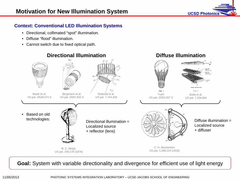
Context: Conventional LED Illumination Systems • Directional, collimated “spot” illumination. • Diffuse “flood” illumination. • Cannot switch due to fixed optical path.
Walezak et al. US pat. 7,744,259
Maxik et al. US pat. D528,673 S
Bergmann et al. US pat. D587,832 S
Directional Illumination
Bolta et al. US pat. 7,234,844
Yuen US pat. D553,267 S
Diffuse Illumination
• Based on old technologies:
M. C. Meigs. US pat. 209,178 (1878)
Directional illumination = Localized source + reflector (lens)
C. H. Muckenhirn US pat. 1,288,124 (1918)
Diffuse illumination = Localized source + diffuser
Goal: System with variable directionality and divergence for efficient use of light energy
PHOTONIC SYSTEMS INTEGRATION LABORATORY – UCSD JACOBS SCHOOL OF ENGINEERING

Waveguide Based Illumination System
11/05/2013
1) LED Sources • High luminance, high efficacy.
2) Coupling
• Tradeoff between spatial power density and divergence.
3) Guiding and Extraction • Confinement by total internal
reflection. • Periodic extraction features
scatter light toward lens array.
LEDs
Couplers
Lens Array
Waveguide Extraction Features 4) Beam Steering & Divergence
• Lenses image extraction features to an infinite conjugate.
• Translations between lenslet and extraction arrays steer total beam by steering individual beams in the same direction.
• Rotations between arrays steer individual beams in different directions, altering divergence of the total beam.
Translated Rotated Aligned
Continuous control over directionality and divergence through small mechanical actuation
PHOTONIC SYSTEMS INTEGRATION LABORATORY – UCSD JACOBS SCHOOL OF ENGINEERING
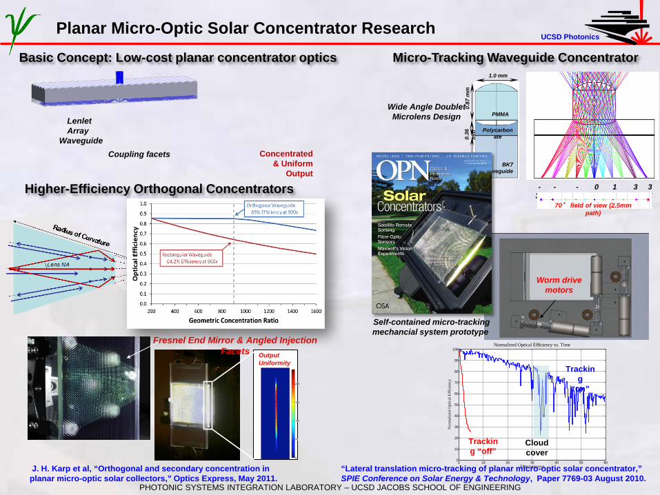
UCSD Photonics Planar Micro-Optic Solar Concentrator Research
Worm drive motors
Output Uniformity
0.87
mm
0.
36
mm
1.
0 m
m
1.0 mm
BK7 Waveguide
PMMA
Polycarbonate
-30°
0°
-15°
30°
15°
35°
-35° 70° field of view (2.5mm
path)
Wide Angle Doublet Microlens Design
Self-contained micro-tracking mechancial system prototype
Micro-Tracking Waveguide Concentrator
Higher-Efficiency Orthogonal Concentrators
“Lateral translation micro-tracking of planar micro-optic solar concentrator,” SPIE Conference on Solar Energy & Technology, Paper 7769-03 August 2010.
J. H. Karp et al, “Orthogonal and secondary concentration in planar micro-optic solar collectors,” Optics Express, May 2011.
Fresnel End Mirror & Angled Injection Facets
0 10 20 30 40 50 600
10
20
30
40
50
60
70
80
90
100Normalized Optical Efficiency vs. Time
Time (minutes)
Nor
mal
ized
Opt
ical
Eff
icie
ncy
Tracking
“on”
Tracking “off”
Cloud cover
Concentrated & Uniform
Output
Coupling facets
Lenlet Array
Waveguide
Basic Concept: Low-cost planar concentrator optics
PHOTONIC SYSTEMS INTEGRATION LABORATORY – UCSD JACOBS SCHOOL OF ENGINEERING

Light Guiding & Extraction • Faceted extraction features: divergence
maintaining, broadband, axially symmetric. • Waveguide confines light by TIR. • Two configurations:
Want thin waveguide.
Design Considerations
LEDs • From conservation of radiance: brightness of
output determined by brightness of source.
Want large package high luminance LEDs.
11/05/2013
Cree Xlamp XM-L2 Active area: 2.5x2.5mm Emittance: 116.5 lm/mm2
Power: 6.2 W Efficacy: 159.13 lm/W
Input
Input
Output
2.5 mm
1) Constant Mode Volume 2) Stepped Mode Volume
Large Source Thin Waveguide
Coupler
Couplers • Efficient coupler must conserve radiance. • Impose above constraints, design becomes
etendue matching problem.
Needed: efficient coupling structure.
Lenses • Determine max. steering angle, crosstalk, and
min. divergence angle.
Want low F/#, low divergence source, small source.
PHOTONIC SYSTEMS INTEGRATION LABORATORY – UCSD JACOBS SCHOOL OF ENGINEERING
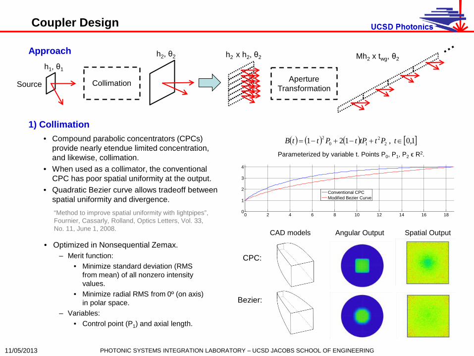
Coupler Design
Approach
11/05/2013
Collimation
h1, θ1 h2, θ2
Source
0 2 4 6 8 10 12 14 16 180
1
2
3
4
Conventional CPCModified Bezier Curve
( ) ( ) ( ) [ ]1,0 , 121 22
102 ∈+−+−= tPttPtPttB
Parameterized by variable t. Points P0, P1, P2 ϵ R2.
CAD models Angular Output Spatial Output
CPC:
Bezier:
1) Collimation • Compound parabolic concentrators (CPCs)
provide nearly etendue limited concentration, and likewise, collimation.
• When used as a collimator, the conventional CPC has poor spatial uniformity at the output.
• Quadratic Bezier curve allows tradeoff between spatial uniformity and divergence.
Aperture Transformation
h2 x h2, θ2 Mh2 x twg, θ2
PHOTONIC SYSTEMS INTEGRATION LABORATORY – UCSD JACOBS SCHOOL OF ENGINEERING
“Method to improve spatial uniformity with lightpipes”, Fournier, Cassarly, Rolland, Optics Letters, Vol. 33, No. 11, June 1, 2008.
• Optimized in Nonsequential Zemax. – Merit function:
• Minimize standard deviation (RMS from mean) of all nonzero intensity values.
• Minimize radial RMS from 0º (on axis) in polar space.
– Variables: • Control point (P1) and axial length.
Coupler Design
11/05/2013
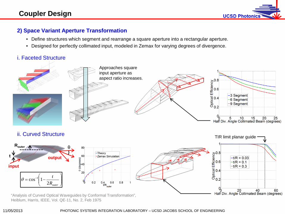
2) Space Variant Aperture Transformation • Define structures which segment and rearrange a square aperture into a rectangular aperture. • Designed for perfectly collimated input, modeled in Zemax for varying degrees of divergence.
i. Faceted Structure
PHOTONIC SYSTEMS INTEGRATION LABORATORY – UCSD JACOBS SCHOOL OF ENGINEERING
ii. Curved Structure
Approaches square input aperture as aspect ratio increases.
input
θ
output t
Router
−= −
outerRt
21cos 1θ
“Analysis of Curved Optical Waveguides by Conformal Transformation”, Heiblum, Harris, IEEE, Vol. QE-11, No. 2, Feb 1975
TIR limit planar guide

Analytic Model & Optimization
11/05/2013
( )12sin θη =beam
( ) ( ) ( )βϕθθθπ β
2222
0 0
2 sinsincos hndSddnGS
== ∫ ∫ ∫( ) ( )
−= −−
211
max tan/#2
1tansinsin θψF
n
= −−
fw
n facet
2tansinsin 11ϕ
( ) ( )2211 sinsin θθ hh = h1
h2
twg
f
φ
ψmax
θ1
θ2
D
1) Constant Mode Volume Waveguide
2) Stepped Mode Volume Waveguide
γ = 45º γ = 45º
D
D
wfacet wfacet
( )γtanwg
facet
tw =
θ
( ) ( )( )( ) ( )
( ) ( ) ( )
+−−
=
= −
θθθθ
ϕθ
sincos1costan
tan/#2cos2
1
NNN
FN
(Waveguide index) (Lens focal length)
(Facet width)
(Waveguide index) (Half divergence angle within waveguide)
(Lens F/# = f/D)
wfacet wfacet
Etendue:
Radiometry:
(Spatial extent) (Half div. angle)
Geometrical Optics:
2
2facet
facet
wA = wgfacet tw 2<
Geometry:
wgtMh ⋅=2
(# of segments) 2 options: facets of # =N
Motivation • Optimization difficult in standard raytracing software. • Create analytic optimization procedure. • Show that optimal designs have useful performance.
Analytic Approach • Use equations from imaging and nonimaging optics. • Find optimal designs in a constrained space. • Verify predicted performance using Zemax.
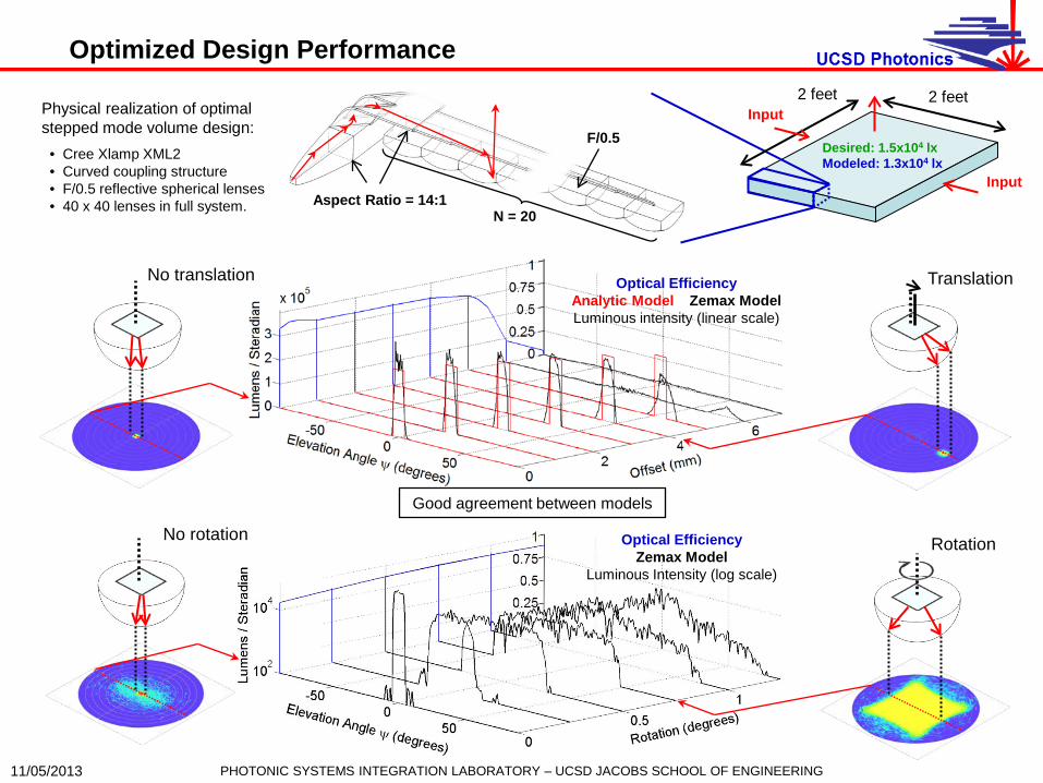
Optimized Design Performance
11/05/2013
N = 20 Aspect Ratio = 14:1
Input
Input Physical realization of optimal stepped mode volume design:
Optical Efficiency Zemax Model
Luminous Intensity (log scale)
Optical Efficiency Analytic Model Zemax Model Luminous intensity (linear scale)
No rotation Rotation
No translation Translation
Good agreement between models
• Cree Xlamp XML2 • Curved coupling structure • F/0.5 reflective spherical lenses • 40 x 40 lenses in full system.
2 feet 2 feet
PHOTONIC SYSTEMS INTEGRATION LABORATORY – UCSD JACOBS SCHOOL OF ENGINEERING
F/0.5 Desired: 1.5x10⁴ lx Modeled: 1.3x10⁴ lx

Simulated System Application
11/05/2013
Conventional 2x2’ system (53W, 4000lm) UCSD SMV2a optimized design, 2x2’ aperture (54.82W, 5700lm)
*Nonlinear Scale
Rotation = 1º Translation: (Δx, Δy) = (-3, 3) mm
Far field intensity modeled in Zemax, exported as .ies file. Room illumination modeled in Dialux software using radiosity method.
• FEM approach to global illumination. Applies to Lambertian surfaces. Iterates through subsequent scattering steps until convergence.
Iterative solution to radiosity method.
Translation: (Δx, Δy) = (5, 0) mm
( ) ( ) ( ) ( ) ( )∫+=S
xx dAxxVisr
xBdAxdAxEdAxB '',coscos' 2'
πθθρ
X Y
PHOTONIC SYSTEMS INTEGRATION LABORATORY – UCSD JACOBS SCHOOL OF ENGINEERING
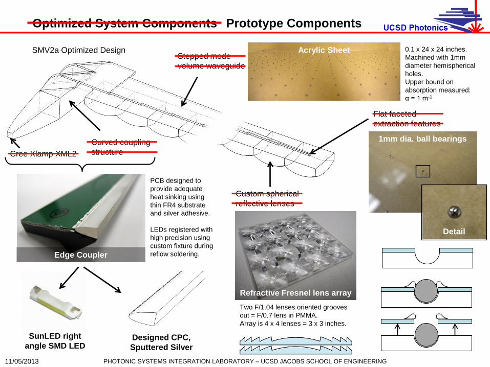
Optimized System Components
11/05/2013
SMV2a Optimized Design Stepped mode volume waveguide
Flat faceted extraction features
Custom spherical reflective lenses
Curved coupling structure Cree Xlamp XML2
Prototype Components
Acrylic Sheet 0.1 x 24 x 24 inches. Machined with 1mm diameter hemispherical holes. Upper bound on absorption measured: α = 1 m-1
Refractive Fresnel lens array Two F/1.04 lenses oriented grooves out = F/0.7 lens in PMMA. Array is 4 x 4 lenses = 3 x 3 inches.
SunLED right angle SMD LED
Designed CPC, Sputtered Silver
Edge Coupler
PCB designed to provide adequate heat sinking using thin FR4 substrate and silver adhesive. LEDs registered with high precision using custom fixture during reflow soldering.
1mm dia. ball bearings
Detail
PHOTONIC SYSTEMS INTEGRATION LABORATORY – UCSD JACOBS SCHOOL OF ENGINEERING
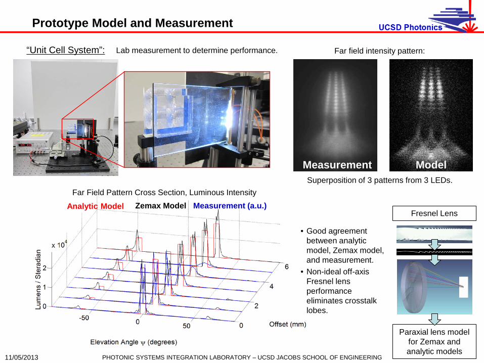
Zemax Model Analytic Model Measurement (a.u.) Far Field Pattern Cross Section, Luminous Intensity
Prototype Model and Measurement
11/05/2013
“Unit Cell System”: Lab measurement to determine performance. Far field intensity pattern:
Superposition of 3 patterns from 3 LEDs.
Measurement Model
Paraxial lens model for Zemax and analytic models
Fresnel Lens
• Good agreement between analytic model, Zemax model, and measurement.
• Non-ideal off-axis Fresnel lens performance eliminates crosstalk lobes.
PHOTONIC SYSTEMS INTEGRATION LABORATORY – UCSD JACOBS SCHOOL OF ENGINEERING
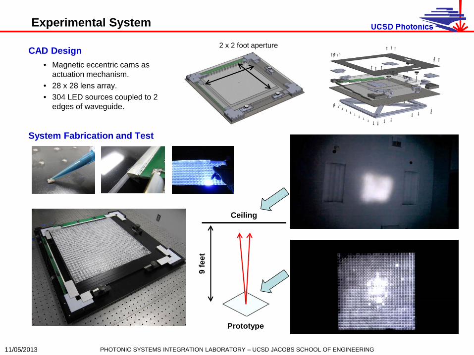
Experimental System
11/05/2013
CAD Design • Magnetic eccentric cams as
actuation mechanism. • 28 x 28 lens array. • 304 LED sources coupled to 2
edges of waveguide.
2 x 2 foot aperture
System Fabrication and Test
PHOTONIC SYSTEMS INTEGRATION LABORATORY – UCSD JACOBS SCHOOL OF ENGINEERING
9 fe
et
Ceiling
Prototype

Summary of Results
11/05/2013
• Design of new illumination system • Continuously variable directionality and divergence
allows efficient use of light energy. • Optimized designs can achieve performance
metrics matching those of conventional illumination systems, while simultaneously providing new functionality.
• Prototype demonstration • Measurements of unit cell prototype validate the
accuracy of Zemax and analytic models used in design process.
• Full 2’ x 2’ experimental system provides proof of principle in a large aperture system.
PHOTONIC SYSTEMS INTEGRATION LABORATORY – UCSD JACOBS SCHOOL OF ENGINEERING
Thank you [email protected]
psilab.ucsd.edu