Embed Size (px)
Citation preview

TECHNICAL & SERVICE MANUAL
CONTENTS
1. SAFETY PRECAUTION ·····················22. PART NAMES AND FUNCTIONS······63. SPECIFICATION·································84. OUTLINES AND DIMENSIONS ·······105. WIRING DIAGRAM···························116. REFRIGERANT SYSTEM DIAGRAM···127. TROUBLESHOOTING······················128. DISASSEMBLY PROCEDURE·········199. PARTS LIST ·····································22
Indoor unit[Model names] [Service Ref.]
PKFY-P20VAM-E PKFY-P20VAM-EPKFY-P25VAM-E PKFY-P25VAM-E
No. OC309
Wall MountedSeries PKFY
INDOOR UNIT
2004SPLIT-TYPE, HEAT PUMP AIR CONDITIONERS
R407C R22R410A
OC309---1.qxp 04.4.14 9:17 AM Page 1

2
1 SAFETY PRECAUTION
[2] Refrigerant recharging(1) Refrigerant recharging process
1Direct charging from the cylinder.·R407C cylinder are available on the market has a syphon pipe.·Leave the syphon pipe cylinder standing and recharge it.(By liquid refrigerant)
(2) Recharge in refrigerant leakage case·After recovering the all refrigerant in the unit, proceed to working.·Do not release the refrigerant in the air.·After completing the repair service, recharge the cycle with the specified amount of liquid refrigerant.
[1] Cautions for service·After recovering the all refrigerant in the unit, proceed to working.·Do not release refrigerant in the air.·After completing the repair service, recharge the cycle with the specified amount of liquid refrigerant.
Cautions for units utilizing refrigerant R407C
CAUTIONS RELATED TO NEW REFRIGERANT
Do not use the existing refrigerant piping.
The old refrigerant and lubricant in the existing piping contains a large amount of chlorine which may cause the lubricant deterioration of the new unit.
Use “low residual oil piping”
If there is a large amount of residual oil (hydraulic oil, etc.) inside the piping and joints, deterioration of the lubricant will result.
Use ESTR , ETHER or HAB as the lubricant to coat flares and flange connection parts.If large amount of mineral oil enter, that can cause deterioration of refrigerant oil etc.
Use liquid refrigerant to seal the system.
If gas refrigerant is used to seal the system, the composition of the refrigerant in the cylinder will change and performance may drop.
Do not use a refrigerant other than R407C.
If another refrigerant (R22, etc.) is used, the chlorine in the refrigerant may cause the lubricant deterioration.
Use a vacuum pump with a reverse flow check valve.
The vacuum pump oil may flow back into the refrigerant cycle and cause the lubricant deterioration.
Store the piping to be used during installation indoors with keep both ends sealed until just before brazing. (Store elbows and other joints in a plastic bag.)
If dust, dirt, or water enters the refrigerant cycle, deterioration of the oil and compressor trouble may result.
Ventilate the room if refrigerant leaks during operation. If refrigerant comes into contact witha flame, poisonous gases will be released.
Gravimeter
Unit
OC309---1.qxp 04.4.14 9:17 AM Page 2
3
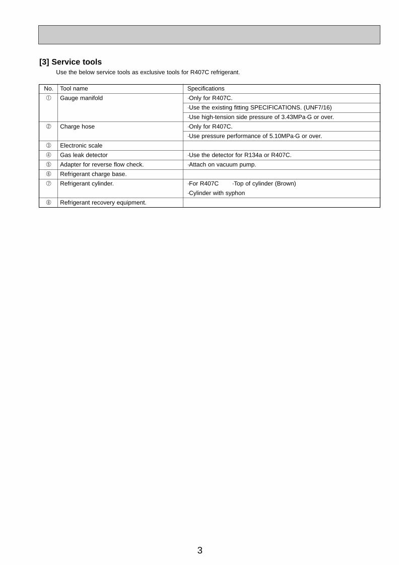
[3] Service toolsUse the below service tools as exclusive tools for R407C refrigerant.
No. Tool name Specifications
1 Gauge manifold ·Only for R407C.
·Use the existing fitting SPECIFICATIONS. (UNF7/16)
·Use high-tension side pressure of 3.43MPa·G or over.
2 Charge hose ·Only for R407C.
·Use pressure performance of 5.10MPa·G or over.
3 Electronic scale
4 Gas leak detector ·Use the detector for R134a or R407C.
5 Adapter for reverse flow check. ·Attach on vacuum pump.
6 Refrigerant charge base.
7 Refrigerant cylinder. ·For R407C ·Top of cylinder (Brown)
·Cylinder with syphon
8 Refrigerant recovery equipment.
OC309---1.qxp 04.4.14 9:17 AM Page 3
4
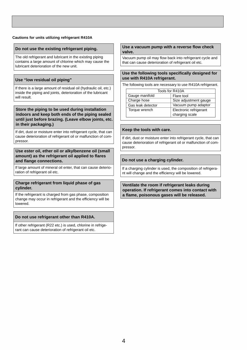
Cautions for units utilizing refrigerant R410A
Store the piping to be used during installationindoors and keep both ends of the piping sealed until just before brazing. (Leave elbow joints, etc. in their packaging.)
Use ester oil, ether oil or alkylbenzene oil (small amount) as the refrigerant oil applied to flares and flange connections.
Charge refrigerant from liquid phase of gascylinder.
If the refrigerant is charged from gas phase, composition change may occur in refrigerant and the efficiency will be lowered.
Do not use refrigerant other than R410A.
If other refrigerant (R22 etc.) is used, chlorine in refrige-rant can cause deterioration of refrigerant oil etc.
Use a vacuum pump with a reverse flow check valve.Vacuum pump oil may flow back into refrigerant cycle and that can cause deterioration of refrigerant oil etc.
Use the following tools specifically designed for use with R410A refrigerant.
The following tools are necessary to use R410A refrigerant.
Keep the tools with care.
If dirt, dust or moisture enter into refrigerant cycle, that cancause deterioration of refrigerant oil or malfunction of com-pressor.
Do not use a charging cylinder.
If a charging cylinder is used, the composition of refrigera-nt will change and the efficiency will be lowered.
Flare tool
Electronic refrigerant charging scale
Vacuum pump adaptorSize adjustment gauge
Gauge manifold
Torque wrenchGas leak detectorCharge hose
Tools for R410A
If dirt, dust or moisture enter into refrigerant cycle, that can cause deterioration of refrigerant oil or malfunction of com-pressor.
If large amount of mineral oil enter, that can cause deterio-ration of refrigerant oil etc.
Do not use the existing refrigerant piping.
The old refrigerant and lubricant in the existing piping contains a large amount of chlorine which may cause the lubricant deterioration of the new unit.
Use “low residual oil piping”
If there is a large amount of residual oil (hydraulic oil, etc.) inside the piping and joints, deterioration of the lubricant will result.
Ventilate the room if refrigerant leaks during operation. If refrigerant comes into contact witha flame, poisonous gases will be released.
OC309---1.qxp 04.4.14 9:17 AM Page 4

5
[1] Cautions for service(1) Perform service after collecting the refrigerant left in unit completely.(2) Do not release refrigerant in the air.(3) After completing service, charge the cycle with specified amount of refrigerant.(4) When performing service, install a filter drier simultaneously.
Be sure to use a filter drier for new refrigerant.
[2] Additional refrigerant chargeWhen charging directly from cylinder· Check that cylinder for R410A on the market is syphon type.· Charging should be performed with the cylinder of syphon stood vertically. (Refrigerant is charged from liquid phase.)
Gravimeter
Unit
[3] Service toolsUse the below service tools as exclusive tools for R410A refrigerant.
No. Specifications
1 Gauge manifold ·Only for R410A
·Use the existing fitting specifications. (UNF1/2)
·Use high-tension side pressure of 5.3MPa·G or over.
2 Charge hose ·Only for R410A
·Use pressure performance of 5.09MPa·G or over.
3 Electronic scale
4 Gas leak detector ·Use the detector for R134a, R407C or R410A.
5 Adaptor for reverse flow check ·Attach on vacuum pump.
6 Refrigerant charge base
7 Refrigerant cylinder ·Only for R410A Top of cylinder (Pink)
Cylinder with syphon
8 Refrigerant recovery equipment
OC309---1.qxp 04.4.14 9:17 AM Page 5
6
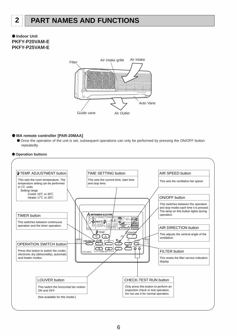
2 PART NAMES AND FUNCTIONS
● Indoor UnitPKFY-P20VAM-EPKFY-P25VAM-E
● MA remote controller [PAR-20MAA]● Once the operation of the unit is set, subsequent operations can only be performed by pressing the ON/OFF button
repeatedly.
● Operation buttons
Air intake grille Air intake
Guide vane Air Outlet
Auto Vane
Filter
PAR-20MAA
ON/OFF
CENTRALLY CONTROLLED
ERROR CODE
CLOCK
ON OFF
˚C
CHECK
CHECK MODEFILTER
TEST RUNFUNCTION
˚C1Hr.
NOT AVAILABLESTAND BY DEFROST
FILTER
CHECK TEST
TEMP.
TIMER SETPress this button to switch the cooler,electronic dry (dehumidify), automaticand heater modes.
OPERATION SWITCH button
This sets the room temperature. Thetemperature setting can be performedin 1: units Setting range Cooler 19: to 30: Heater 17: to 28:
TEMP. ADJUSTMENT button
This switches between continuousoperation and the timer operation.
TIMER button
This switches between the operationand stop modes each time it is pressed.The lamp on this button lights duringoperation.
ON/OFF button
Only press this button to perform aninspection check or test operation.Do not use it for normal operation.
CHECK-TEST RUN button
This switch the horizontal fan motionON and OFF.
(Not available for this model.)
LOUVER button
This adjusts the vertical angle of theventilation.
AIR DIRECTION button
This resets the filter service indicationdisplay
FILTER button
This sets the current time, start time and stop time.
TIME SETTING button
This sets the ventilation fan speed.
AIR SPEED button
OC309---1.qxp 04.4.14 9:17 AM Page 6
7
PAR-20MAA
ON/OFF
CENTRALLY CONTROLLED
ERROR CODE
CLOCK
ON OFF
˚C
CHECK
CHECK MODEFILTER
TEST RUNFUNCTION
˚C1Hr.
NOT AVAILABLESTAND BY DEFROST
FILTER
CHECK TEST
TEMP.
TIMER SET
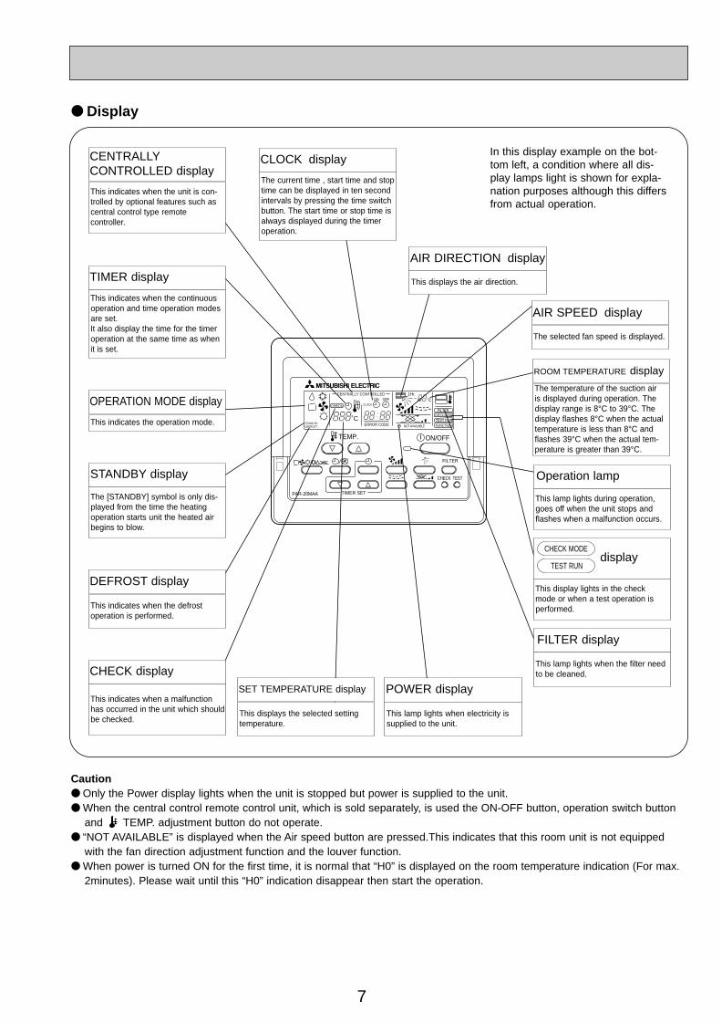
Caution● Only the Power display lights when the unit is stopped but power is supplied to the unit.● When the central control remote control unit, which is sold separately, is used the ON-OFF button, operation switch button
and TEMP. adjustment button do not operate.● “NOT AVAILABLE” is displayed when the Air speed button are pressed.This indicates that this room unit is not equipped
with the fan direction adjustment function and the louver function.● When power is turned ON for the first time, it is normal that “H0” is displayed on the room temperature indication (For max.
2minutes). Please wait until this “H0” indication disappear then start the operation.
CENTRALLYCONTROLLED display
This indicates when the unit is con-trolled by optional features such ascentral control type remote controller.
TIMER display
This indicates when the continuousoperation and time operation modesare set.It also display the time for the timeroperation at the same time as whenit is set.
OPERATION MODE display
This indicates the operation mode.
STANDBY display
The [STANDBY] symbol is only dis-played from the time the heatingoperation starts unit the heated airbegins to blow.
DEFROST display
This indicates when the defrost operation is performed.
CHECK display
This indicates when a malfunctionhas occurred in the unit which shouldbe checked.
CLOCK display
The current time , start time and stoptime can be displayed in ten secondintervals by pressing the time switchbutton. The start time or stop time isalways displayed during the timeroperation.
● Display
In this display example on the bot-tom left, a condition where all dis-play lamps light is shown for expla-nation purposes although this differsfrom actual operation.
Operation lamp
This lamp lights during operation,goes off when the unit stops andflashes when a malfunction occurs.
POWER display
This lamp lights when electricity issupplied to the unit.
SET TEMPERATURE display
This displays the selected settingtemperature.
AIR DIRECTION display
This displays the air direction.
ROOM TEMPERATURE display
The temperature of the suction air is displayed during operation. Thedisplay range is 8°C to 39°C. Thedisplay flashes 8°C when the actualtemperature is less than 8°C andflashes 39°C when the actual tem-perature is greater than 39°C.
display
This display lights in the check mode or when a test operation isperformed.
CHECK MODE
TEST RUN
This lamp lights when the filter needto be cleaned.
AIR SPEED display
The selected fan speed is displayed.
FILTER display
OC309---1.qxp 04.4.14 9:17 AM Page 7
8
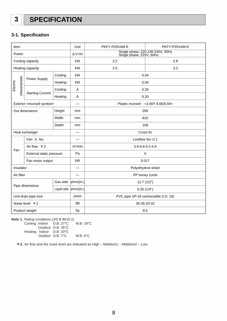
3 SPECIFICATION
3-1. Specification
Power Supply
Starting Current
Fan ✕ No.
Air flow w 2
External static pressure
Fan motor output
Item
Power
Cooling capacity
Heating capacity
Exterior <munsell symbol>
Out dimensions
Heat exchanger
Fan
Insulator
Air filter
Pipe dimensions
Unit drain pipe size
Noise level w 2
Product weight
Unit
[,V,Hz
kW
kW
kW
kW
A
A
—
mm
mm
mm
—
—
K/min
Pa
kW
—
—
[mm(in.)
[mm(in.)
[mm
dB
kg
Cooling
Heating
Cooling
Heating
Height
Width
Depth
Gas side
Liquid side
PKFY-P20VAM-E
2.2
2.5
PKFY-P25VAM-E
2.8
3.2
0.04
0.04
0.20
0.20
Plastic munsell : <2.60Y 8.66/0.69>
295
815
158
Cross fin
Lineflow fan ✕ 1
5.9-5.6-5.2-4.9
0
0.017
Polyethylene sheet
PP honey comb
12.7 (1/2")
6.35 (1/4")
PVC pipe VP-16 connectable (I.D. 16)
36-35-33-32
8.5
Ele
ctric
char
acte
ristic
Single phase, 220-230-240V, 50HzSingle phase, 220V, 60Hz
Note 1. Rating conditions (JIS B 8615-1)Cooling : Indoor D.B. 27°C W.B. 19°C
Outdoor D.B. 35°CHeating : Indoor D.B. 20°C
Outdoor D.B. 7°C W.B. 6°C
ww 2. Air flow and the noise level are indicated as High – Middium1 – Middium2 – Low.
OC309---1.qxp 04.4.14 9:17 AM Page 8
9
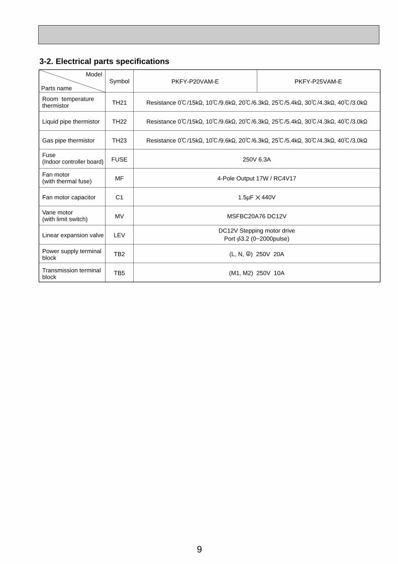
3-2. Electrical parts specifications
Parts name
ModelSymbol
TH21
TH22
TH23
FUSE
MF
C1
MV
LEV
TB2
TB5
Resistance 0:/15k", 10:/9.6k", 20:/6.3k", 25:/5.4k", 30:/4.3k", 40:/3.0k"
Resistance 0:/15k", 10:/9.6k", 20:/6.3k", 25:/5.4k", 30:/4.3k", 40:/3.0k"
Resistance 0:/15k", 10:/9.6k", 20:/6.3k", 25:/5.4k", 30:/4.3k", 40:/3.0k"
250V 6.3A
4-Pole Output 17W / RC4V17
1.5µF ✕ 440V
MSFBC20A76 DC12V
(L, N, ;) 250V 20A
(M1, M2) 250V 10A
Liquid pipe thermistor
Gas pipe thermistor
Fan motor capacitor
Linear expansion valve
PKFY-P20VAM-E PKFY-P25VAM-E
Room temperaturethermistor
Fuse(Indoor controller board)
Fan motor(with thermal fuse)
Vane motor(with limit switch)
Power supply terminalblock
Transmission terminalblock
DC12V Stepping motor drivePort [3.2 (0~2000pulse)
OC309---1.qxp 04.4.14 9:17 AM Page 9

10
4 OUTLINES AND DIMENSIONS
Unit : mm78
3
C
D
B
CB
AD
25.5 13
Air
inta
ke d
imen
sion
Air
inta
ke d
imen
sion
Air
outle
t dim
ensi
on
Dra
in p
ipe
leng
th
Gas
pip
e
Det
ail o
f Ter
min
al b
lock Te
rmin
al b
lock
for
tran
smis
sion
Term
inal
blo
ck fo
r tr
ansm
issi
on
Term
inal
blo
ck fo
r po
wer
sup
ply
Add
ress
boa
rd
Term
inal
blo
ck fo
r po
wer
sup
ply
Kno
ck o
ut h
ole
for
right
- h
and
side
pip
ing
Kno
ck o
ut h
ole
for
left
- ha
ndsi
de p
ipin
g
Kno
ck o
ut h
ole
for
unde
r pi
ping
Liqu
id p
ipe
815
630
695
660
450
520
54
50
16 4591
.510
34
2.5
2.516
450
10
455
45
3
R15
R15
R15
R12
R8
R8
R8
10
24.4
116
11060
146
295
21.5
247.
515
0
2.5
60
13
Det
ail o
f kno
ck o
ut h
ole
(A B
C)
Sec
onda
ry
Prim
ary
Kno
ck o
ut h
ole
for
the
rem
ote
cont
rolle
r w
iring
Kno
ck o
ut h
ole
for
the
rem
ote
cont
rolle
r w
iring
: In
case
of c
onne
ctin
g M
A r
emot
e co
ntro
ller,
use
the
cab
le w
ith th
e co
nnec
tor
atta
ched
to th
e in
door
uni
t. P
leas
e co
nnec
t the
cab
le w
ith th
e co
nnec
tor
with
the
lea
d w
ire a
nd c
onne
ctor
(R
elay
con
nect
or)
for
the
MA
rem
ote
cont
rolle
r of
indo
or c
ontr
olle
r bo
ard.
: The
re is
no
term
inal
boa
rd fo
r M
A r
emot
e co
ntro
ller.
Air intake dimension
PKFY-P20VAM-EPKFY-P25VAM-E
A
159
407.5
328 328
298
235
235
205
205
175
175
170
170
10
100
298
407.5
168
135
125
110
35 10 27.5
40 53 65 87 113
128
0
295
260
260
225
225
190
190180
159155
155
120
120
85
85
30
3045 4450
0
133
122.
597
.5 85 6047
.522
.5 15 9010
2.5
124 4-
4.5✕
35
4-4
.5✕
40 4
-4.5
✕37 4
-11✕
20
8-
4.3
0
72.5
Air intake dimension
Air
inta
keIn
stal
latio
n pl
ate
Kno
ck o
ut h
ole
Inst
alla
tion
spac
e
100
or m
ore
20 or more
20 or more
130
or m
ore
Add
ress
boa
rd
Dra
in p
ipe
Liqu
id p
ipe
Fla
re c
onne
ctio
n 1/
4F
Fla
re c
onne
ctio
n 1/
2FG
as p
ipe
Refri
gera
ntpi
pe
Add
ress
boa
rd is
pro
tect
ed b
yth
e pl
astic
cov
er.
For
the
setti
ng, r
emar
k 1-
scre
wus
ing
the
scre
w d
river
.
Inst
alla
tion
plat
e
Air
outle
tan
gle
Air
outle
t di
men
sion
Air
outle
t dire
ctio
n
Det
ail o
fad
dres
s bo
ard
Dip
sw
itch
Term
inal
blo
ck
158
70.3
37.4
5
80
4-
9
12-
2.8
87-
5.1
65
17
3
1
1
Not
e1. F
or th
e in
stal
latio
n, b
e su
re to
leav
e so
me
spac
e in
cas
e th
ere
is fr
inge
at e
dge
of th
e ce
iling
.N
ote2
. Use
the
M10
or
W3/
8 bo
lt fo
r th
e in
stal
latio
n pl
ate.
Not
e3. R
efer
for
the
spec
ifica
tion
tabl
e it
belo
w . Co
nnec
tion
inne
r dim
ensio
n [
16
Lota
ry s
witc
h(pa
rt N
o.)
Lota
ry s
witc
h(se
lf ad
dres
s)
54 or more for left or left back piping
Uni
t tra
nspl
ant p
arts
pipe
hol
e
Pos
ition
det
ail o
f the
tapp
ing
scre
w a
nd b
ats
at p
ipe
inta
ke
Cen
ter
of g
ravi
ty h
ole
for
inst
alla
tion
OC309---1.qxp 04.4.14 9:17 AM Page 10
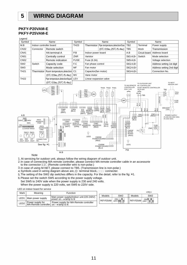
11
WIRING DIAGRAM5
1 2to the connector . (Remote controller wire is non-polar.)
TB5
TB2
NL
TO NEXT INDOOR UNIT
PULL BOX
FUSE(15A)
~/N 220V 60Hz~/N 220-230-240V 50Hz
BREAKER (15A)
POWER SUPPLY
GR
N/Y
LW
OR
N
OR
N
PKFY-P20VAM
Models
OFFON
Models SW2
<w1>
SW2
PKFY-P25VAM4321 4321
OFFON
Mark
LED1
LED2
Meaning
Main power supply
Function
Power supply forMA-Remote controller
LED on indoor board for service
Main power supply(Indoor unit:220-240V)power on lamp is litPower supply for MA-Remote controlleron lamp is lit
3.In case of using M-NET, please connect to TB5. (Transmission line is non-polar.)
In case of connecting MA-remote controller, please connect MA remote controller cable in an accessorie2.
CN35PMICONBOARD(BLU)
CN53PMICONBOARD(RED)
(BLU)
(RED)
POWER BOARD
POWER BOARDCN53M
CN35M
CN43ADDRESS
(RED)
(RED)ADDRESSCN82
SW5220V 240V
3RDDIGIT
2NDDIGIT
1STDIGIT
CONNECTIONNO.
See fig: w1
(WHT)
CENTRALLYCONTROL
(GRN)
REMOTEINDICATION
(RED)ADDRESS
(RED)ADDRESS (BLU)
CN20INTAKE(RED)
(BLU)
(GRN) (RED)
BLU
RE
D
BLK
RE
D
WH
TB
LU
BLU
M-NET REMOTE CONTROLLER
TO OUTDOOR UNITBC CONTROLLER
CONTROLLERTO MA-REMOTE
LIQUID(WHT)(BLK)
GAS(GRN)
PNK
YLWORNBLU
RED
SWITCH(WHT)(WHT)
(WHT)
RED
WHTYLWORNBLU
BRN
6.5.4.
1.Note
The setting of the SW2 dip switches differs in the capacity. For the detail, refer to the fig: w1.Symbols used in wiring diagram above are, : terminal block, : connecter.
At servicing for outdoor unit, always follow the wiring diagram of outdoor unit.
Please set the switch SW5 according to the power supply voltage.Set SW5 to 240V side when the power supply is 230 and 240 volts.When the power supply is 220 volts, set SW5 to 220V side.
block
Terminal
Switch
Circuit board
Power supply
TransmissionAddress board
Mode selection
Address setting 1st digit
Connection No.
Address setting 2nd digit
Name
Voltage selection
Vane motorMV
Fan motor
(0:/15T,25:/5.4T) TB5
TB2
SW14<A.B>SW12<A.B>SW11<A.B>
SW1<A.B>
A.B
Pipe temperature,detection/Gas
Capacitor(fan motor)C1
MF
TH23 Thermistor
SW3
SW2 Switch
CN52
CN51
CN41
CN32
Indoor controller board
NameSymbol
M.B
Legend
Connector Remote switchHA terminal-ACentrally controlRemote indication
Mode selectionCapacity code
P.B Indoor power board
Symbol Name Symbol
ZNR Varistor
Fuse (6.3A)FUSE
Fan phase controlF.C
(0:/15T,25:/5.4T)Pipe temperature,detection/liquid(0:/15T,25:/5.4T)
Room temperature,detectionThermistorTH21
TH22 Linear expansion valveLEV
SW5<A.B>
CN5V(BLU) CN41
HA REMOTECN32 CN34 CN29
LEVCN60
CN3ACN81CN42CN52CN51
12
34
56
78
910
SW
3
0FF
0N
12
34
SW
2
LED2
M.B
CN21
CN2MM-NET
FAN CND
C1FUSE250V6.3A
8
4
ONOFF
12345678910
SW1
SW12 SW11 SW14
A.B
0 0 0
LED1
TH22TH23 TH21
5
MF
M1 M2
DC24-30VDC8.7-13V {
P.B
ZNRF.C
MV
{
21
LEV6
654321 1 2 3 4 5 4321 1 2 3 1 2 3 1 2 21
321 4 5 321 4 541 2 3 61 2 3 4 5 7 8 31 1 2
1 32 4 5
1 2 3
12345678
1234
54
23
1
321
1 2 1 4 6 1 3
123456
12345
PKFY-P20VAM-EPKFY-P25VAM-E
OC309---1.qxp 04.4.14 9:17 AM Page 11

TROUBLESHOOTING7
12
6 REFRIGERANT SYSTEM DIAGRAM
7-1. How to check PKFY-P20VAM-E PKFY-P25VAM-E
Strainer (#100mesh)
Strainer (#50mesh)
Heat exchanger
Room temperature thermistorTH21
Gas pipe temperature thermistorTH23
Liquid pipe temperature thermistorTH22
Gas pipe
Liquid pipe
Flare
Linear expansion
valve
Gas pipe
PKFY-P20VAM-E PKFY-P25VAM-E
{12.7 (1/2”)
Liquid pipe {6.35 (1/4”)
ModelsItem
PKFY-P20VAM-EPKFY-P25VAM-E
Parts name Check points
Disconnect the connector then measure the resistance using a tester.(Surrounding temperature 10:~30:)
Disconnect the connector then measure the resistance valve using a tester.(Coil temperature 20:)
Vane motor
Linear expansion valve
Refer to the next page for the details.
Room temperaturethermistor (TH21) Liquid pipe temperaturethermistor (TH22) Gas pipe temperaturethermistor (TH23)
Normal
4.3k"~9.6k"
Abnormal
Open or short
Normal
150" ±10%
Abnormal
(1)-(5)White-Red
(2)-(6)Yellow-Brown
(3)-(5)Orange-Red
(4)-(6)Blue-Brown Open or short
Measure the resistance between the terminals using a tester. (Surrounding temperature 25:)
Normal Normal
200" ±7%
Abnormal
1-2Red-Pink
1-3Red-Blue
1-4Red-Orange
1-5Red-Yellow Open or short
1 Measure the resistance between the terminals using a tester. (Surrounding temperature 20:)
2 Without disassembling the parts, measure the electrical pressure of the gray wire (Signal line) and brown wire (GND) while the power is on.
Fan motor
Abnormal
Open or shortWhite-Black
Red-Black
Normal
195"
200"
Abnormal
Normal
(1) At first, check if the electrical pressure is 12V between the brown wire (GND) and yellow wire (VCC).
(2) Slowly start running the fan. It is normal if while the fan rotate once, the electrical pressure change from 0V to12V then go back to 0V.
If the electrical pressure stay at around 0V or 10V, it means the fan motor has the defects.
Blue
YellowRed
Orange Pink
3
5
1
4 2Connect pin No.
M
WhiteRed
Black
Brown Gray Yellow
CN34
1
4
6
3 2 1
FAN
123456
LEV
White
Yellow
Orange
Blue
Red
Brown
CN60
OC309---1.qxp 04.4.14 9:17 AM Page 12
13
0
10
20
30
40
50
-20 -10 0 10 20 30 40 50
< Thermistor for lower temperature >
Temperature (:)
Res
ista
nce
(K"
)
4 [4
3
6
5
[3
2 [2
1 [1
[4
[3
[2
[1
Controller board
Drive circuit
Connector(CN60)
DC12V
Brown
Red
Blue
Orange
Yellow
White
M
4
6
2
3
51
Blue
Brown
Yellow
OrangeRedWhite
Linear expansion valve
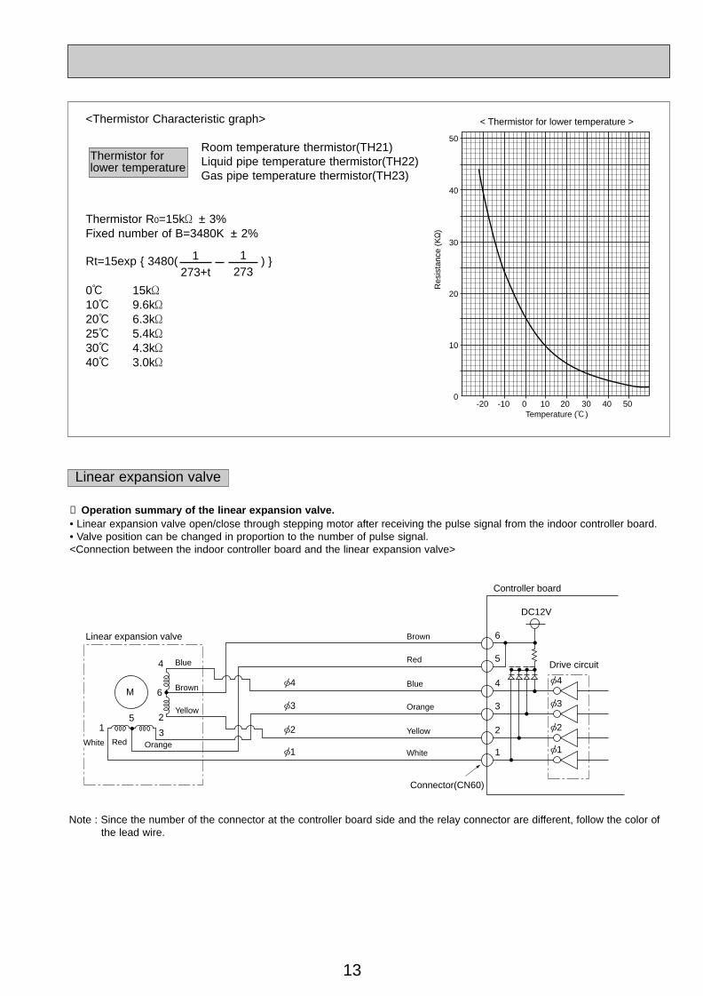
<Thermistor Characteristic graph>
Room temperature thermistor(TH21)Liquid pipe temperature thermistor(TH22)Gas pipe temperature thermistor(TH23)
Thermistor R0=15k' ± 3%Fixed number of B=3480K ± 2%
Rt=15exp { 3480( ) }
0: 15k'10: 9.6k'20: 6.3k'25: 5.4k'30: 4.3k'40: 3.0k'
Thermistor for lower temperature
Linear expansion valve
① Operation summary of the linear expansion valve.• Linear expansion valve open/close through stepping motor after receiving the pulse signal from the indoor controller board.• Valve position can be changed in proportion to the number of pulse signal.<Connection between the indoor controller board and the linear expansion valve>
1273+t
1273
Note : Since the number of the connector at the controller board side and the relay connector are different, follow the color ofthe lead wire.
OC309---1.qxp 04.4.14 9:17 AM Page 13

14
Output(Phase)
Output
{1
1
ON
{2 ON
{3 OFF
{4 OFF
2
OFF
ON
ON
OFF
3
OFF
OFF
ON
ON
4
ON
OFF
OFF
ON
<Output pulse signal and the valve operation>
➁ Linear expansion valve operation
➂ Trouble shooting
D
A
E
B
C
Open
Extra tightning (80~100pulse)
Pulse number
2000 pulseOpening a valveall the way
Close
Val
ve p
ositi
on (
capa
city
)
654321
LED1k'
Symptom Check points
Operation circuit fail-ure of the microprocessor.
Disconnect the connector on the controller board, then con-nect LED for checking.
Pulse signal will be sent out for 10 seconds as soon as themain switch is turn on. If there is LED with lights on or lightsoff, it means the operation circuit is abnormal.
Countermeasures
Exchange the indoor con-troller board at drive circuitfailure.
Linear expansionvalve mechanism islocked.
Valve doesn't closecompletely (thermis-tor leaking).
Wrong connection ofthe connector orcontact failure.
To check the linear expansion valve, operate the indoor unitin fan mode and at the same time operate other indoor unitsin cooling mode, then check the pipe temperature <liquid
pipe temperature> of the indoor unit by theoutdoor multi controller board operationmonitor. During fan operation, linearexpansion valve is closed completely and ifthere are some leaking, detecting tempera-ture of the thermistor will go lower. If thedetected temperature is much lower thanthe temperature indicated in the remote
controller, it means the valve is not closed all the way. It isnot necessary to exchange the linear expansion valve, if theleakage is small and not making any trouble.
Thermistor
Linearexpansionvalve
Motor will idle and make ticking noise when motor is operatedwhile the linear expansion valve is locked. This ticking soundis the sign of the abnormality.
Check the color of lead wire and missing terminal of the con-nector.
Exchange the linearexpansion valve.
Exchange the linearexpansion valve.
If large amount of thermis-tor is leaked, exchange thelinear expansion valve.
Disconnect the connectorat the controller board,then check the continuity.
Measure the resistance between the each coil (red-white,red-orange, brown-yellow, brown-blue) using a tester. It isnormal if the resistance is in the range of 150'+10%.
Short or breakage ofthe motor coil of thelinear expansionvalve.
Closing a valve : 1 → 2 → 3 → 4 → 1Opening a valve : 4 → 3 → 2 → 1 → 4
The output pulse shift in above order.❈ 1. When linear expansion valve operation stops, all output phase
become OFF.2. At phase interruption or when phase does not shift in order,
motor does not rotate smoothly and motor lock, and vibrates.
❈ When the switch is turned on, 2200 pulse closing valve signalwill be send till it goes to A point in order to define the valveposition.
When the valve move smoothly, there is no noise or vibrationoccurring from the linear expansion valve ; however, when thepulse number moves from E to A or when the valve is locked,more noise can be heard than normal situation.
❈ Noise can be detected by placing the ear against the screw dri-ver handle while putting the screw driver to the linear expansionvalve.
OC309---1.qxp 04.4.14 9:17 AM Page 14

15
7-2. FUNCTION OF DIP SWITCH
PKFY-P20VAM-E PKFY-P25VAM-E
1
2
3
4
5
6
7
8
9
10
1~4
1
2
3
4
5
6
7
8
9
10
Thermistor<Intake temperature>position
ON OFF
Filter clogging Provide Not provide
Filter sign indication 2,500 hr 100 hr
Air intake Not effective Not effective
Remote indication switching Thermostat ON signal indication Fan output indication
Humidifier control Fan operation at Heating mode Heat thermostat ON is operating
Low Extra low
Setting air flow Reset to SW1-7
Auto restart function Effective Not effective
Power ON/OFF Effective Not effective
Heat pump/Cool only Cooling only Heat pump
Capacity save Available Not available
Vane Available Not available
Not available Available
Vane horizontal angle Second setting First setting
Vane cooling limit angle setting Horizontal angle Down B,C
Effective Not effective
Heater 4 degreed up Not effective Effective
Target Superheat setting temperature 9 degreed 6 degreed
Target Subcool setting temperature 15 degreed 10 degreed
ONOFF
1 2 3 4 5 6 7 8 9 10
ONOFF
1 2 3 4 5 6 7 8 9 10
ONOFF
1 2 3 4
ONOFF
1 2 3 4
PKFY-P20VAM-E
MODEL SW2
PKFY-P25VAM-E
Address board<At delivery>
Indoor controller board
Indoor controller board
<At delivery>
SW3Functionselection
SW2Capacity
codeswitch
SW1Mode
selection
Switch Pole FunctionOperation by switch
Remarks
Built-in remote controller Indoor unit
Indoor linear expansionvalve opening
w1 SW1-7=OFF, SW1-8=ON→Setting air flow.SW1-7=OFF, SW1-8=ON→Indoor fan stop.
w2 It is impossible to intakethe fresh air.
Set while the unit is off.
<At delivery>
Set for each capacity.
Set while the unit is off.
(Note 1) At cooling mode, eachangle can be used only 1hour.
Reading change of LEV openingon reversion of after defrosting
Air flow at heat thermostatOFF
NOTE:
w1w1
w1
w2
w1
OC309---1.qxp 04.4.14 9:17 AM Page 15

16
0
5
9
4
8 37
2
6
1
SW12
10
0
5
9
4
8 37
2
6
1
SW11
1
0
8
F
7
E
6
D 5C
4
B
3
A
2
9
1
SW14
0
5
9
4
8 37
2
6
1
SW120
5
9
4
8 37
2
6
1
SW11
0
8
F
7
E
6
D 5C
4
B
3
A
2
9
1
SW14
Address board
Address board
Operation by switchSwitch Remarks
<At delivery>
<At delivery>
SW111st digitaddresssettingSW12
2nd digitaddresssetting
Rot
ary
switc
h
SW14Connection
No.Setting
SW5 Voltage
selection
Rot
ary
switc
h
Address setting should be done when M-NETremote controller is being used.
This is the switch to be used when the indoorunit is operated with R2 series outdoor unit as a set.
If the unit is used at the 230V or 240V area,set the voltage to 240V.If the unit is used at the 220V, set the voltageto 220V.
Address can be set while theunit is stopped.
Address board
2
220V 240V<At delivery>
220V 240V
OC309---1.qxp 04.4.14 9:17 AM Page 16

17
7-3. TEST POINT DIAGRAM7-3-1. Indoor controller board PKFY-P20VAM-EPKFY-P25VAM-E
CN3AConnect to the MA-Remote controller Between 11 to 33 8.7-13V DC (Pin11 (+))
CN29Pipe temperature thermistor/Gas (TH23)
CN21Pipe temperature thermistor/Liquid (TH22)
CN32Connector (Remote switch)
CN60Linear expansion valve output (LEV)
SW3Mode selection
CN51Centrally control
SW2Capacity setting
CN52Remote indication
CN6VVane moter output (MV)
CN20Room temperature thermistor (TH21)
CN53MConnect to the indoor power board (CN53P)Between 11 to 22 24-30V DC (non-polat)Between 33 to 55 12.5-13.7V DC (Pin33 (+))Between 44 to 55 11.5-12.7V DC (Pin44 (+))
CN35MConnect to the indoor power board (CN35P)
LED2Power supply forMA-Remote controller
CN41Connector(HA terminal-A)
CN34Fan motor rotational frequency input (MF)
OC309---1.qxp 04.4.14 9:17 AM Page 17

18
7-3-2. Indoor power boardPKFY-P20VAM-EPKFY-P25VAM-E
FUSE6.3A 250V
CN53PConnect to the indoor controller board (CN53M)Between 11 to 22 24-30V DC (non-polat)Between 33 to 55 12.5-13.7V DC (Pin33 (+))Between 44 to 55 11.5-12.7V DC (Pin44 (+))
LED1Main power supply(Indoor unit : 220-240V)
CN35PConnect to the indoor controller board(CN35M)
CN2MConnect to the terminal block (TB5)(M-NET transmission connecting wire)24-30V DC (non-polar)
FANFan motor output (MF)
CNDPower supply for indoor controller board Between 11 to 33 220-240V AC
OC309---1.qxp 04.4.14 9:17 AM Page 18

19
DISASSEMBLY PROCEDURE8
OPERATION PROCEDURE PHOTOS & ILLUSTRATIONS
1. REMOVING THE LOWER SIDE OF THE INDOOR UNIT FROMTHE INSTALLATION PLATE
When there is removing plate(1) Remove the corner box at right lower side of the indoor
unit.(2) Insert the removing plate at the back side of the corner box
to remove the indoor unit.(3) Remove the hook by pulling the lower side of the indoor unit
down as shown in the figure 1.
When there is no removing plate or it can not be used for somereason.(1) Remove the front panel.(2) Insert the screw driver to the corner hole at both left and
right side as shown in the figure 2.(3) Push it up then, pull down the lower side of indoor unit and
remove the hook.
Indoor unitremoving plate
Insertthe edge Pull
PushCorner hole
1 2
Push Down
Be carefulnot to damage the airflow adjustmentplate with thescrew driver.
PKFY-P25VAM-E Be careful on removing heavy parts.
Figure 1 Figure 2
2. REMOVING THE FRONT PANEL
❈ Before removing the front panel, leave the open space atupper side of air flow adjustment plate approximately 2 to 3cm.
(1) Remove the screw caps then remove the set screws.(Refer to the photo 1)
(2) Remove the left side of the front panel, then right side.(3) After removing the lower side of the front panel a little,
remove it as pulling the upper side toward you.❈ Please pay attention to the nozzle assemble.
INSTALLING THE FRONT PANEL(1) Insert the lower side of the front panel under the air
adjustment plate.(2) Set the upper side of the front panel.(3) Set the lower side of the front panel then fix it with the
screws.(4) Press the area indicated as arrow sign and set it to the air
conditioner unit.
Push4
13
2
Photo 1
Figure 3
Front panel
Set screws
Airflow adjustment plate
OC309---1.qxp 04.4.14 9:17 AM Page 19
20
OPERATION PROCEDURE PHOTOS & ILLUSTRATIONS
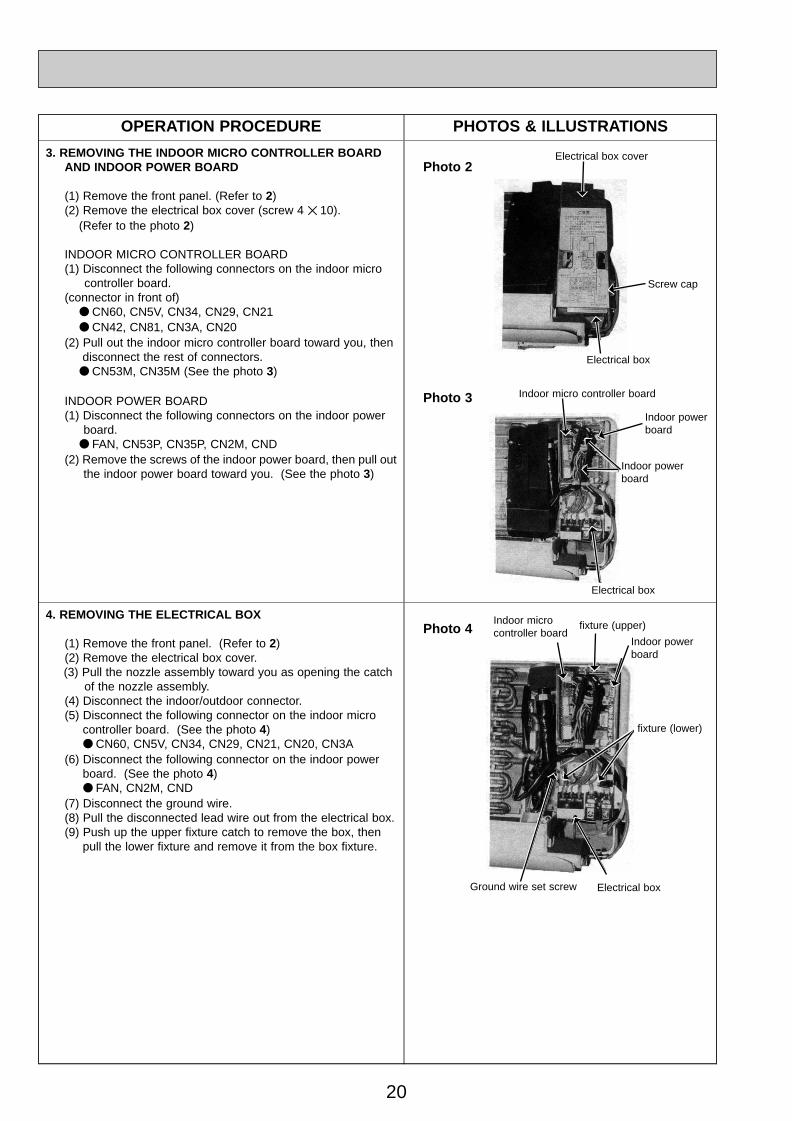
3. REMOVING THE INDOOR MICRO CONTROLLER BOARDAND INDOOR POWER BOARD
(1) Remove the front panel. (Refer to 2)(2) Remove the electrical box cover (screw 4 ✕ 10).
(Refer to the photo 2)
INDOOR MICRO CONTROLLER BOARD(1) Disconnect the following connectors on the indoor micro
controller board.(connector in front of)
● CN60, CN5V, CN34, CN29, CN21● CN42, CN81, CN3A, CN20
(2) Pull out the indoor micro controller board toward you, then disconnect the rest of connectors.
● CN53M, CN35M (See the photo 3)
INDOOR POWER BOARD(1) Disconnect the following connectors on the indoor power
board.● FAN, CN53P, CN35P, CN2M, CND
(2) Remove the screws of the indoor power board, then pull outthe indoor power board toward you. (See the photo 3)
Photo 2Electrical box cover
Screw cap
Electrical box
Photo 3 Indoor micro controller board
Indoor powerboard
Indoor powerboard
4. REMOVING THE ELECTRICAL BOX
(1) Remove the front panel. (Refer to 2)(2) Remove the electrical box cover.(3) Pull the nozzle assembly toward you as opening the catch
of the nozzle assembly.(4) Disconnect the indoor/outdoor connector.(5) Disconnect the following connector on the indoor micro
controller board. (See the photo 4)● CN60, CN5V, CN34, CN29, CN21, CN20, CN3A
(6) Disconnect the following connector on the indoor powerboard. (See the photo 4)● FAN, CN2M, CND
(7) Disconnect the ground wire.(8) Pull the disconnected lead wire out from the electrical box.(9) Push up the upper fixture catch to remove the box, then
pull the lower fixture and remove it from the box fixture.
Photo 4Indoor microcontroller board
fixture (upper)
Indoor powerboard
fixture (lower)
Ground wire set screw Electrical box
Electrical box
OC309---1.qxp 04.4.14 9:17 AM Page 20

21
OPERATION PROCEDURE PHOTOS & ILLUSTRATIONS
5. REMOVING THE NOZZLE ASSEMBLY
(1) Remove the front panel (Refer to 2).(2) Remove the electrical box cover.(3) Disconnect the connector (CN5V) on the indoor micro con
troller board.(4) After unhook the right side of the corner box, press the
upper left side and remove the corner box.(5) Remove the nozzle assemble from the fixture.
(See the photo 5)(6) Remove the drain hose.
Photo 5
Heat exchanger Electrical box
fixture
Drain hose
6. REMOVING THE LINE FLOW FAN AND THE FAN MOTOR
(1) Remove the front panel. (Refer to 2)(2) Remove the nozzle assembly. (Refer to 5)(3) Remove the electrical parts box.(4) Remove the fixture while pressing the right side of motor
fixture catch. (See the photo 6)(5) Remove the left side of the motor fixture.(6) Loosen the screw which fixes the line flow fan to the fan
motor, then remove the fan motor by sliding it to the rightside. (See the photo 6)
(7) Pull the left-hand side of the heat exchanger toward you.(See the photo 7)
(8) Remove the line flow fan.
Photo 6Heat exchanger Fan motor
Photo 7 Heat exchanger
7. REMOVING THE VANE MOTOR
(1) Remove the front panel.(2) Remove the screw of the electrical parts box cover, and
remove the cover.(3) Remove the screw of the vane motor, and remove the motor
from the shaft.(4) Disconnect the vane motor connector (CN5V) on the indoor
controller board.
Photo 8Heat exchanger
Vane motor
Nozzle assembly
8. REMOVING THE LIQUID PIPE THERMISTOR AND GASPIPE THERMISTOR
(1) Remove the front panel. (Refer to 2)(2) Remove the electrical box cover.(3) Remove the pipe cover.(4) Cut the wiring fixed band.(5) Remove the liquid pipe thermistor and gas pipe thermistor.
(See the photo 9)(6) Disconnect the connector (CN29) (CN21) on the indoor
micro controller board.
Photo 9Heat exchanger
Drain hose
fixture set screwsset screws
Drain hoseNozzle assembly
fixture (left)
Nozzle assembly
fixture
Line flow fan
Heat exchangerfixture (left)
Vane motor connectscrews
Liquid pipe thermis-tor
Gas pipe thermistor
Electrical box
fixture (right)
OC309---1.qxp 04.4.14 9:17 AM Page 21

22
9 PARTS LIST
PANEL PARTSPKFY-P20VAM-EPKFY-P25VAM-E
1
2
3
4
5
6
7
8
9
10
BOX
FRONT PANEL
AIR FILTER
INTAKE GRILLE
SCREW CAP
RECEVING COVER
GRILLE CATCH
CORNER BOX
BACK PLATE
BRAND LABEL
No. Parts No. Parts Name Specifications PKFY-P20VAM-EPKFY-P25VAM-E
Remarks(Drawing No.)
WiringDiagramSymbol
Recom-mended
Q'tyUnit Amount
Q'ty / set Price
1
1
1
1
1
1
1
1
1
1
3PCS/SET
(DT25C174H03)
(BC79R798H02)
R01 22A 635
R01 22A 651
R01 22A 500
R01 22A 691
R01 22A 096
—
R01 22A 054
T7W A00 658
R01 22A 808
—
Part number that is circled is not shown in the figure.
OC309---1.qxp 04.4.14 9:17 AM Page 22
23
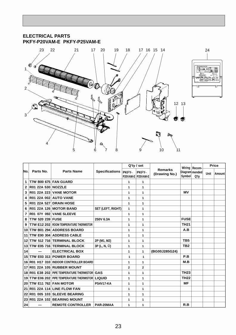
ELECTRICAL PARTSPKFY-P20VAM-E PKFY-P25VAM-E
1
2
3
4
5
6
7
8
9
10
11
12
13
14
15
16
17
18
19
20
21
22
23
24
FAN GUARD
NOZZLE
VANE MOTOR
AUTO VANE
DRAIN HOSE
MOTOR BAND
VANE SLEEVE
FUSE
ROOM TEMPERATURE THERMISTOR
ADDRESS BOARD
ADDRESS CABLE
TERMINAL BLOCK
TERMINAL BLOCK
ELECTRICAL BOX
POWER BOARD
INDOOR CONTROLLER BOARD
RUBBER MOUNT
PIPE TEMPERATURE THERMISTOR
PIPE TEMPERATURE THERMISTOR
FAN MOTOR
LINE FLOW FAN
SLEEVE BEARING
BEARING MOUNT
REMOTE CONTROLLER
SET (LEFT, RIGHT)
250V 6.3A
2P (M1, M2)
3P (L, N, ;)
GAS
LIQUID
PS4V17-KA
PAR-20MAA
No. Parts No. Parts Name Specifications PKFY-P25VAM-E
PKFY-P20VAM-E
Remarks(Drawing No.)
WiringDiagramSymbol
Recom-mended
Q'tyUnit Amount
Q'ty / set Price
MV
FUSE
TH21
A.B
TB5
TB2
P.B
M.B
TH23
TH22
MF
R.B
1
1
1
1
1
1
1
1
1
1
1
1
1
1
1
1
2
1
1
1
1
1
1
1
1
1
1
1
1
1
1
1
1
1
1
1
1
1
1
1
2
1
1
1
1
1
1
1
(BG00J285G24)
T7W B00 675
R01 22A 530
R01 22A 223
R01 22A 002
R01 22A 527
R01 22A 126
R01 07Y 092
T7W 520 239
T7W E12 202
T7W B01 294
T7W E00 304
T7W 512 716
T7W E05 716
—
T7W E03 313
R01 H17 310
R01 22A 105
R01 E38 202
T7W E06 202
T7W E11 762
R01 22A 114
R01 005 103
R01 22A 102
—
1
2
3
4
5 8 109 11
12 13
23 22 21 17 20 1719 18 141516
PAR-20MAA
ON/OFF
CENTRALLY CONTROLLED
ERROR CODE
CLOCK
ON OFF
˚C
CHECK
CHECK MODEFILTER
TEST RUNFUNCTION
˚C1Hr.
NOT AVAILABLESTAND BY DEFROST
FILTER
CHECK TEST
TEMP.
TIMER SET
24
6 7
OC309---1.qxp 04.4.14 9:17 AM Page 23

cCopyright 2004 MITSUBISHI ELECTRIC ENGINEERING CO., LTD.Distributed in Apr. 2004. No. OC309 PDF 9 Made in Japan
HEAD OFFICE : MITSUBISHI DENKI BLDG., 2-2-3, MARUNOUCHI, CHIYODA-KU TOKYO 100-8310, JAPAN
New publication, effective Apr. 2004Specifications subject to change without notice
HEAT EXCHANGER PARTSPKFY-P20VAM-EPKFY-P25VAM-E
1
2
3
HEAT EXCHANGER
HEAT EXCHANGER
CONNECT PIPE
LINEAR EXPANSION VALVE
No. Parts No. Parts Name Specifications PKFY-P20VAM-E
PKFY-P25VAM-E
Remarks(Drawing No.)
WiringDiagramSymbol
Recom-mended
Q'tyUnit Amount
Q'ty / set Price
R01 H58 480
R01 H59 480
R01 E03 470
R01 E63 401
1
1
1
1
1
1 LEV
1
3
2
OC309---1.qxp 04.4.14 9:17 AM Page 24


![Service Manual · Service Manual SiUS711114 [Applied Models] VAM 300GVJU VAM 470GVJU VAM 600GVJU VAM1200GVJU Energy Recovery Ventilator](https://img.dokumen.tips/doc/110x75/5b8f613509d3f20e308c4cbc/service-manual-service-manual-sius711114-applied-models-vam-300gvju-vam-470gvju.jpg)