Embed Size (px)
Citation preview

PILED FOUNDATION PILED FOUNDATION DESIGN & CONSTRUCTIONDESIGN & CONSTRUCTION
By Ir. Dr. Gue See Sew & Ir. Chow Chee Menghttp://www.gnpgeo.com.my
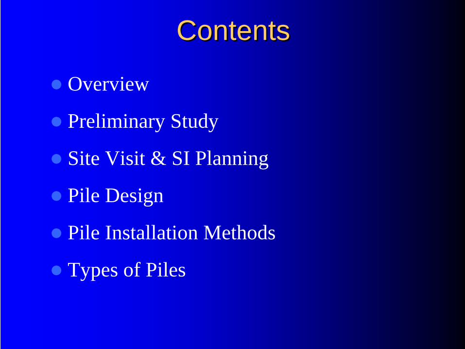
ContentsContents
Overview
Preliminary Study
Site Visit & SI Planning
Pile Design
Pile Installation Methods
Types of Piles
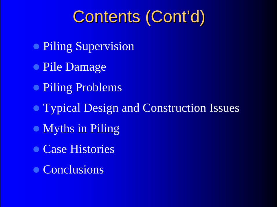
Contents (ContContents (Cont’’d)d)Piling Supervision
Pile Damage
Piling Problems
Typical Design and Construction Issues
Myths in Piling
Case Histories
Conclusions
Overview
What is a Pile Foundation
It is a foundation system that transfers loads to a deeper and competent soil layer.
When To Use Pile Foundations
• Inadequate Bearing Capacity of Shallow
Foundations
• To Prevent Uplift Forces
• To Reduce Excessive Settlement

PILE CLASSIFICATIONPILE CLASSIFICATION
Friction Pile– Load Bearing Resistance derived mainly
from skin friction
End Bearing Pile– Load Bearing Resistance derived mainly
from base
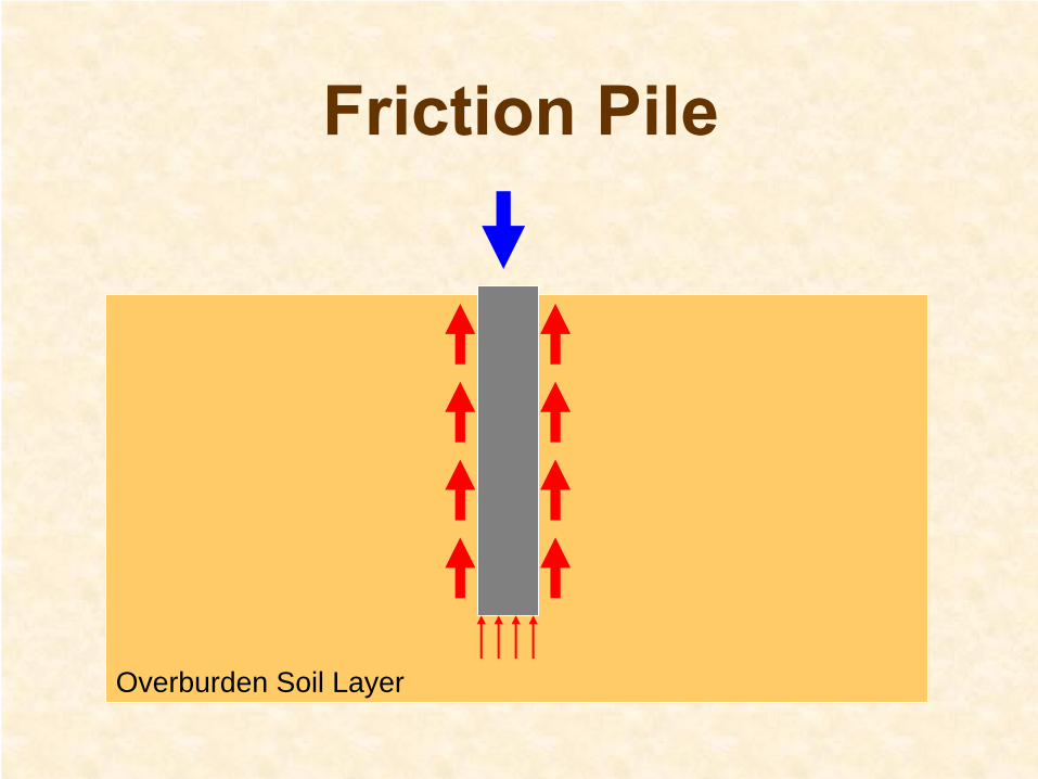
Friction Pile
Overburden Soil Layer
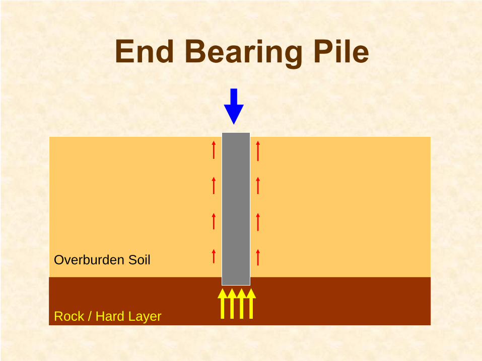
End Bearing Pile
Rock / Hard Layer
Overburden Soil

Preliminary Study
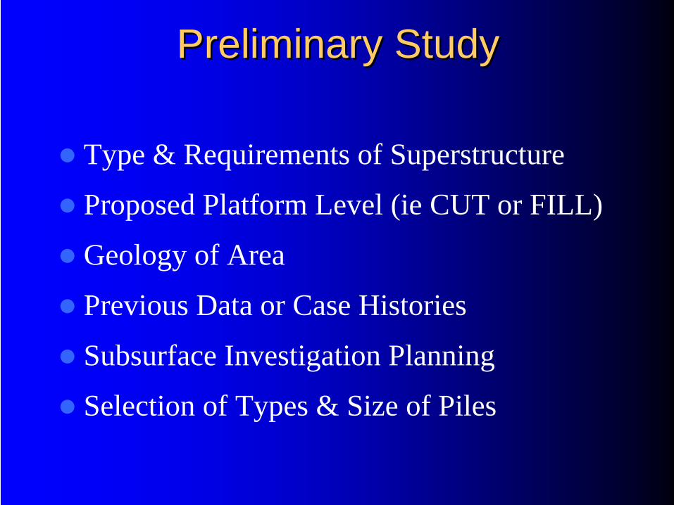
Preliminary StudyPreliminary Study
Type & Requirements of Superstructure
Proposed Platform Level (ie CUT or FILL)
Geology of Area
Previous Data or Case Histories
Subsurface Investigation Planning
Selection of Types & Size of Piles
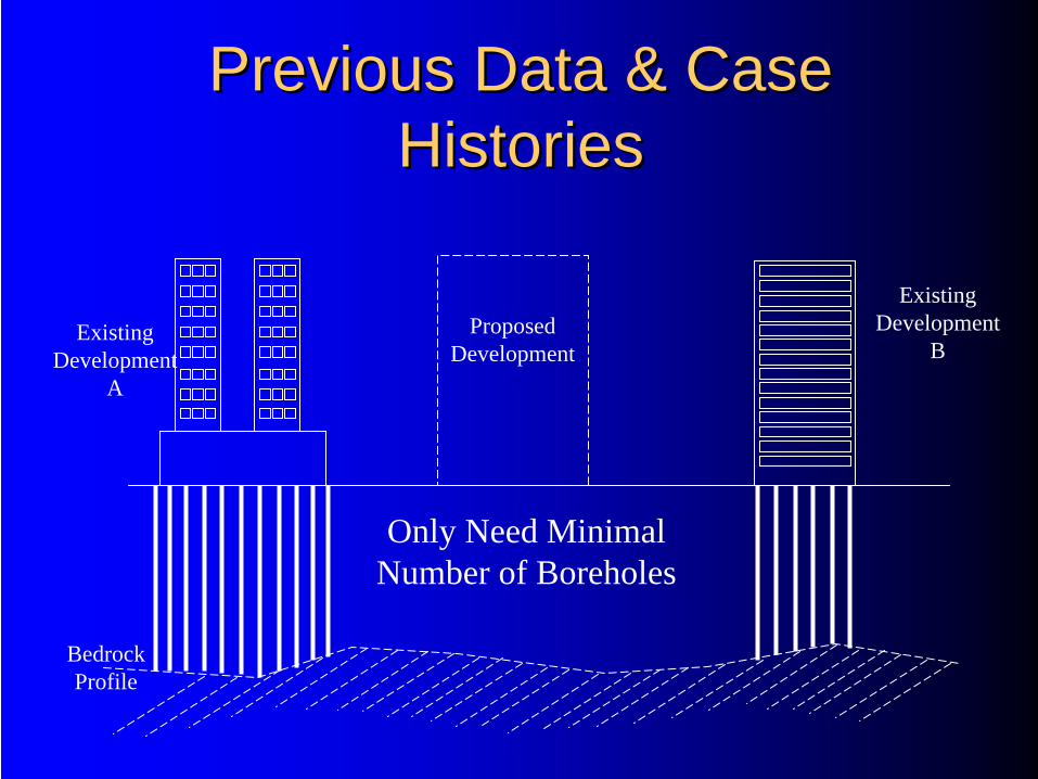
Previous Data & Case Previous Data & Case HistoriesHistories
Bedrock Profile
Existing Development
A
Existing Development
BProposed
Development
Only Need Minimal Number of Boreholes
Challenge The Norm Thru Innovation To Excel
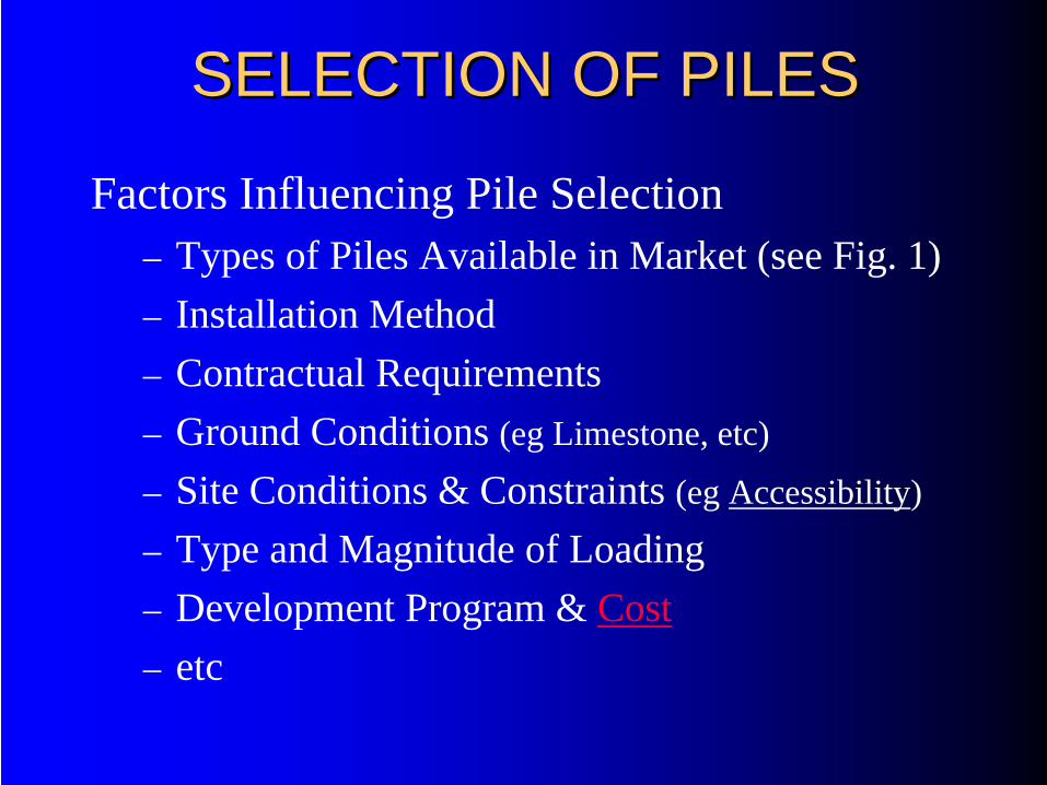
SELECTION OF PILESSELECTION OF PILES
Factors Influencing Pile Selection– Types of Piles Available in Market (see Fig. 1)– Installation Method– Contractual Requirements– Ground Conditions (eg Limestone, etc)
– Site Conditions & Constraints (eg Accessibility)
– Type and Magnitude of Loading– Development Program & Cost– etc
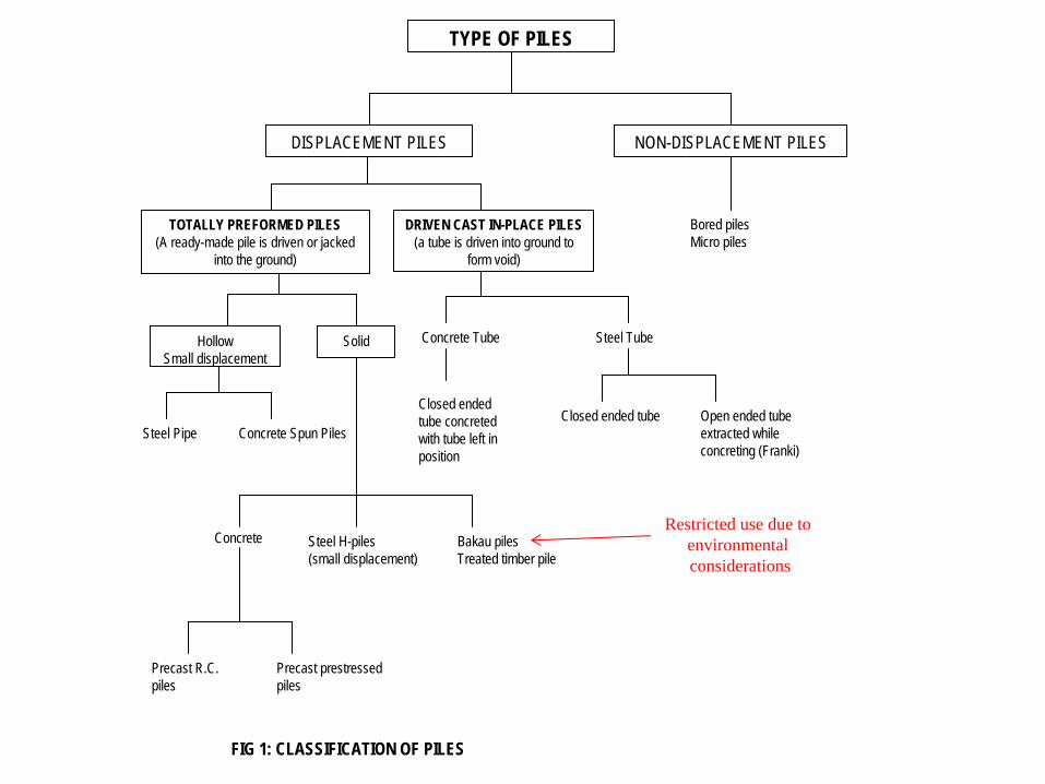
TYPE OF PILES
DISPLACEMENT PILES NON-DISPLACEMENT PILES
TOTALLY PREFORMED PILES(A ready-made pile is driven or jacked
into the ground)
DRIVEN CAST IN-PLACE PILES(a tube is driven into ground to
form void)
Bored piles Micro piles
HollowSmall displacement
Solid
Steel Pipe Concrete Spun Piles
Concrete Tube
Closed ended tube concreted with tube left in position
Closed ended tube
Steel Tube
Open ended tube extracted while concreting (Franki)
Concrete Steel H-piles(small displacement)
Bakau pilesTreated timber pile
Precast R.C. piles
Precast prestressed piles
FIG 1: CLASSIFICATION OF PILES
Restricted use due to environmental considerations
BA
KA
U P
ILE
S
TIM
PE
R P
ILE
S
RC
PIL
ES
PS
C P
ILE
S
SP
UN
PIL
ES
STE
EL
H P
ILE
S
STE
EL
PIP
E P
ILE
S
JAC
KE
D P
ILE
S
<100 KN a a a ? ? ? ? a x ? a
100-300 a a a ? ? a a a x a a
300-600 ? a a a a a a a a a a
600-1100 x ? a a a a a ? a a ?
1100-2000 x ? a a a a a ? a a ?
2000-5000 x x a a a a a ? a a ?
5000-10000 x x a a a a a x a a x
>10000 x x ? a a a a x a ? x
<5m ? ? ? ? ? ? ? x a a ?
5-10m a a a a a a a ? a a a
10-20m ? ? a a a a a a a a a
20-30m x x a a a a a a a a a
30-60m x x a a a a a a a ? a
a a a a a ? a a a ? a
a a a a a a a a a ? a
? ? ? ? ? a a a ? a a
x x a a a a a ? a a ?x x ? ? ? a a ? a a ?x ? a a a a a a a a a
a a a a a a a a a ? a
a a a a a a a a a a a
? a a a a a a a a a a
x ? a a a a a a a a a
a a a a a a a a a a a
? a a a a a a a a a a
x ? a a a a a a a a a
V. DENSE SPT > 50 x x a a a a a ? a a ?
S < 100 mm x ? a a a a a a a a ?
100-1000mm x x ? ? ? a a ? a a x
1000-3000mm x x ? ? ? ? ? ? ? a x
>3000mm x x ? ? ? ? ? ? ? a x
a a a a a a a a a a a
x a a a a a a a a a a
a a ? ? ? ? ? a a a a
? ? ? ? ? ? ? a ? a a
1-2 0.5-2 1.5-3 1-2.5
AU
GE
RE
D P
ILE
S
COMPRESSIVE LOAD PER COLUMN
SC
ALE
OF
LOA
D
(STR
UC
TUR
AL)
1.0-3.5
PREVENTION OF EFFECTS ON ADJOINING STRUCTURES
(SUPPLY & INSTALL) RM/TON/M 0.5-2.5 0.3-2.0
LOOSE SPT < 10
UNIT COST
GROUND WATER
TYP
E O
F IN
TER
ME
DIA
TE L
AY
ER
GE
OTE
CH
NIC
AL TY
PE
OF
BE
AR
ING
LA
YE
RB
EA
RIN
G T
YP
E
ENVIRONMENT
MIC
RO
PIL
ES
BO
RE
D P
ILE
S
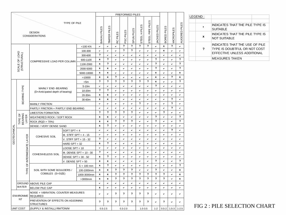
PREFORMED PILES
M. DENSE SPT = 10 - 30
MAINLY END -BEARING (D=Anticipated depth of bearing)
PARTLY FRICTION + PARTLY END BEARING
MAINLY FRICTION
LIMESTON FORMATION
M. STIFF SPT = 4 - 15
V. STIFF SPT = 15 - 32
HARD SPT > 32
DENSE / VERY DENSE SAND
SOFT SPT < 4
WEATHERED ROCK / SOFT ROCK
NOISE + VIBRATION; COUNTER MEASURES REQUIRED
BELOW PILE CAP
ROCK (RQD > 70%)
DENSE SPT = 30 - 50
COHESIVE SOIL
COHESIVELESS SOIL
SOIL WITH SOME BOULDERS / COBBLES (S=SIZE)
ABOVE PILE CAP
DESIGN CONSIDERATIONS
TYPE OF PILE
LEGEND :
8
x
?
INDICATES THAT THE PILE TYPE IS SUITABLEINDICATES THAT THE PILE TYPE IS NOT SUITABLE
INDICATES THAT THE USE OF PILE TYPE IS DOUBTFUL OR NOT COST EFFECTIVE UNLESS ADDITIONAL
MEASURES TAKEN
FIG 2 : PILE SELECTION CHART

Site Visit and SI Planning
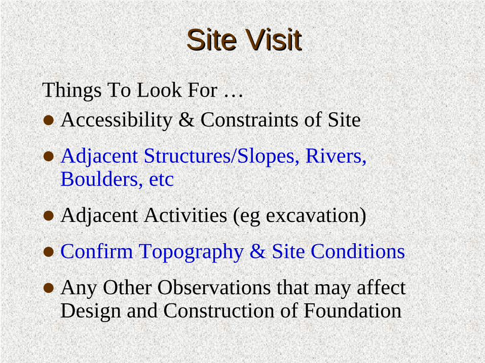
Site VisitSite VisitThings To Look For …
Accessibility & Constraints of Site
Adjacent Structures/Slopes, Rivers, Boulders, etc
Adjacent Activities (eg excavation)
Confirm Topography & Site Conditions
Any Other Observations that may affect Design and Construction of Foundation

Subsurface Investigation (SI) Subsurface Investigation (SI) PlanningPlanning
Provide Sufficient Boreholes to get Subsoil Profile
Collect Rock Samples for Strength Tests (eg UCT)
In-Situ Tests to get consistency of ground (eg SPT)
Classification Tests to Determine Soil Type Profile
Soil Strength Tests (eg CIU)
Chemical Tests (eg Chlorine, Sulphate, etc)
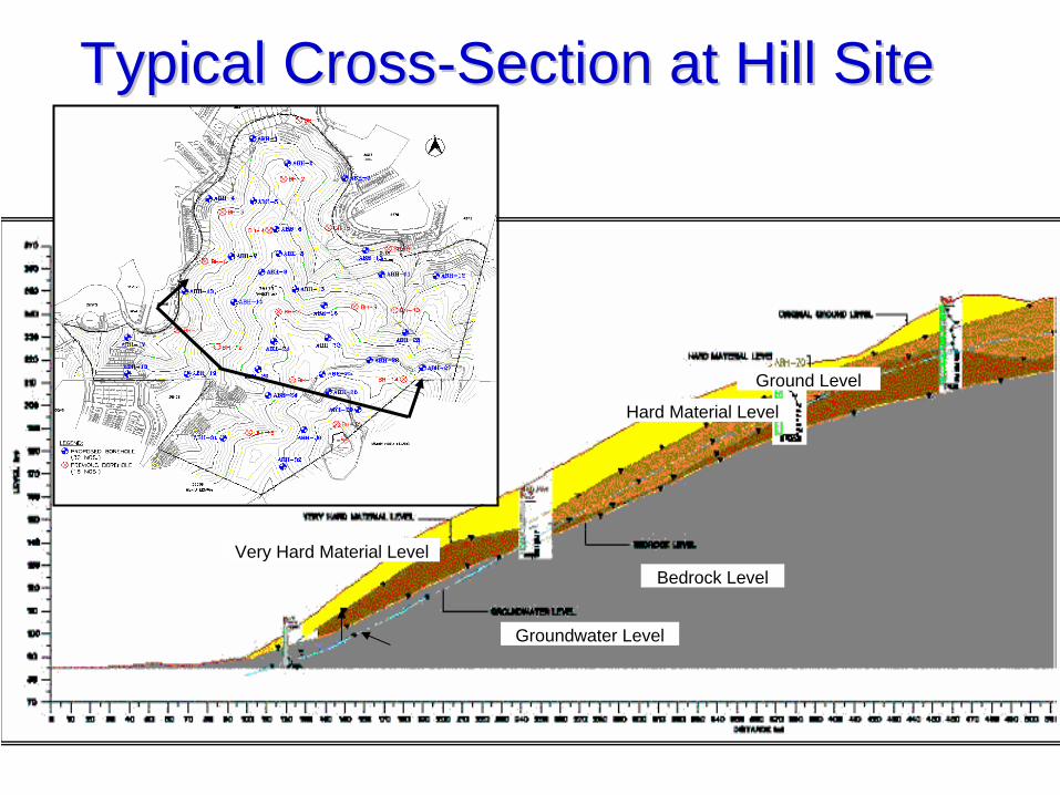
Typical CrossTypical Cross--Section at Hill Site Section at Hill Site
Ground Level
Bedrock LevelVery Hard Material Level
Hard Material Level
Groundwater Level
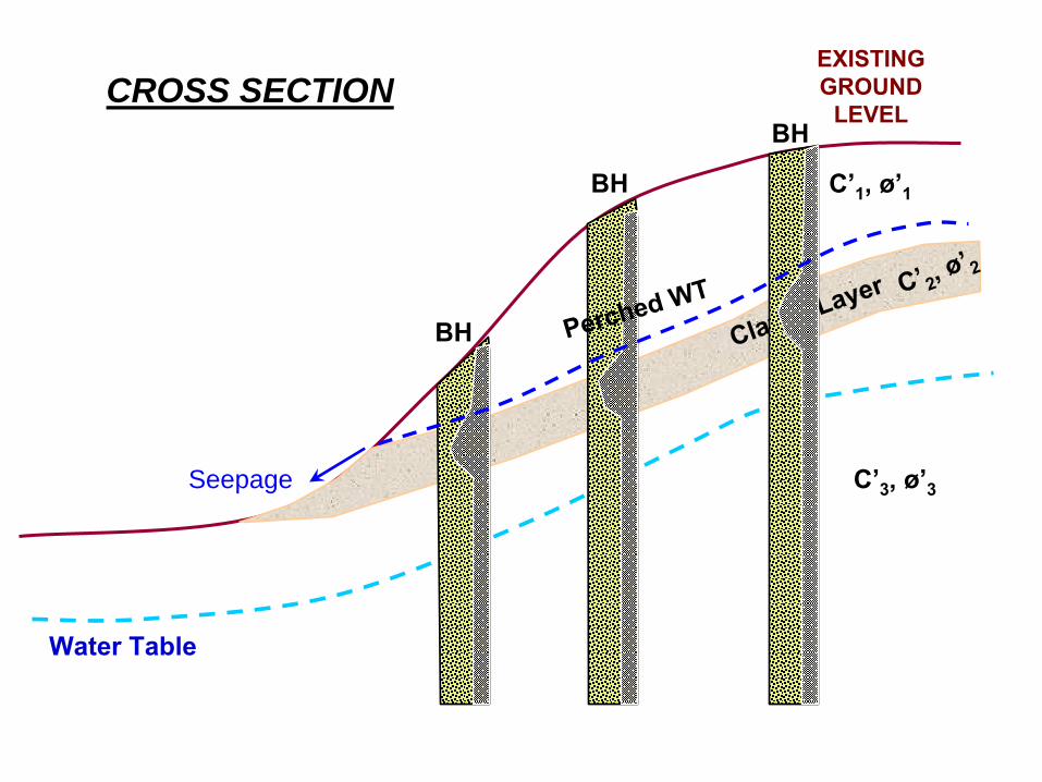
EXISTING GROUND
LEVEL
Water Table
C’2, ø’2
Clayey Layer
C’3
, ø’3
C’1
, ø’1
BH
BH
BH Perched WT
Seepage
CROSS SECTION
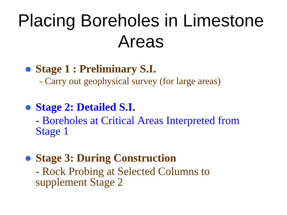
Placing Boreholes in Limestone Areas
Stage 1 : Preliminary S.I.- Carry out geophysical survey (for large areas)
Stage 2: Detailed S.I. - Boreholes at Critical Areas Interpreted from Stage 1
Stage 3: During Construction- Rock Probing at Selected Columns to supplement Stage 2
Pile Design
PILE DESIGNPILE DESIGN
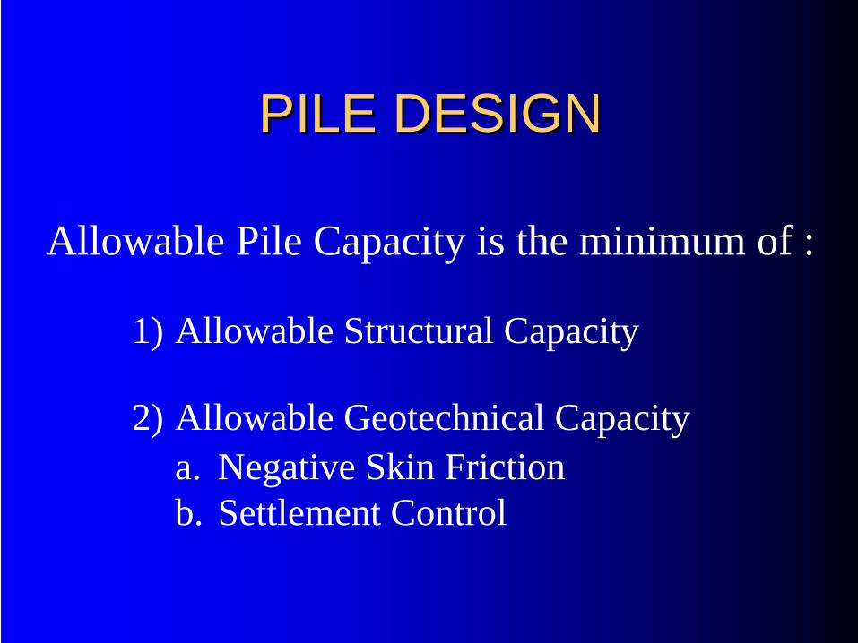
Allowable Pile Capacity is the minimum of :
1) Allowable Structural Capacity
2) Allowable Geotechnical Capacitya. Negative Skin Frictionb. Settlement Control
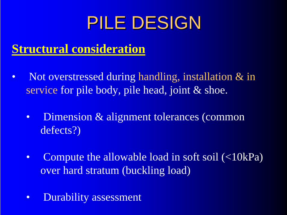
PILE DESIGNPILE DESIGNStructural consideration
• Not overstressed during handling, installation & in service for pile body, pile head, joint & shoe.
• Dimension & alignment tolerances (common defects?)
• Compute the allowable load in soft soil (<10kPa) over hard stratum (buckling load)
• Durability assessment
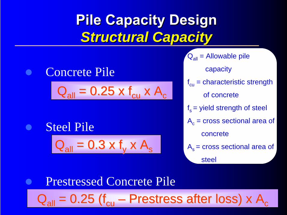
Pile Capacity Design Pile Capacity Design Structural CapacityStructural Capacity
Concrete Pile
Steel Pile
Prestressed Concrete Pile
QQallall = 0.25 x = 0.25 x ffcucu x Ax Acc
QQallall = 0.3 x = 0.3 x ffyy x Ax Ass
QQallall = 0.25 (= 0.25 (ffcucu –– PrestressPrestress after loss) x Aafter loss) x Acc
Qall = Allowable pile
capacity
fcu = characteristic strength
of concrete
fs = yield strength of steel
Ac = cross sectional area of
concrete
As = cross sectional area of
steel
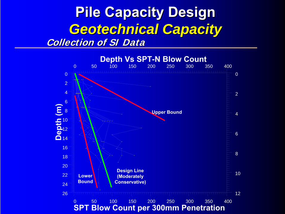
SPT Blow Count per 300mm Penetration
Collection of SI DataCollection of SI Data
Pile Capacity Design Pile Capacity Design Geotechnical CapacityGeotechnical Capacity
4000 50 100 150 200 250 300 35026
24
22
20
18
16
14
12
10
8
6
4
2
0
12
10
8
6
4
2
0
0 50 100 150 200 250 300 350 400D
epth
(m)
Upper Bound
Lower Bound
Design Line (Moderately
Conservative)
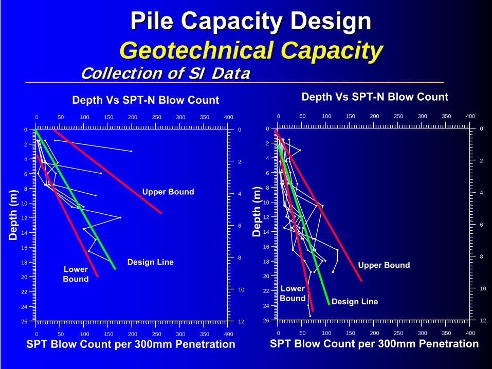
Depth Vs SPT-N Blow Count
0 50 100 150 200 250 300 350 400
26
24
22
20
18
16
14
12
10
8
6
4
2
0
12
10
8
6
4
2
0
0 50 100 150 200 250 300 350 400
0 50 100 150 200 250 300 350 400
26
24
22
20
18
16
14
12
10
8
6
4
2
0
12
10
8
6
4
2
0
0 50 100 150 200 250 300 350 400
Upper Bound
Lower Bound
Design Line Upper Bound
Lower Bound Design Line
Dep
th (m
)
Depth Vs SPT-N Blow Count
SPT Blow Count per 300mm Penetration
Dep
th (m
)
Depth Vs SPT-N Blow Count
SPT Blow Count per 300mm Penetration
Collection of SI DataCollection of SI Data
Pile Capacity Design Pile Capacity Design Geotechnical CapacityGeotechnical Capacity
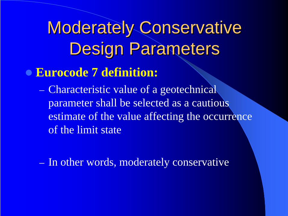
Moderately Conservative Moderately Conservative Design ParametersDesign Parameters
Eurocode 7 definition:– Characteristic value of a geotechnical
parameter shall be selected as a cautious estimate of the value affecting the occurrence of the limit state
– In other words, moderately conservative
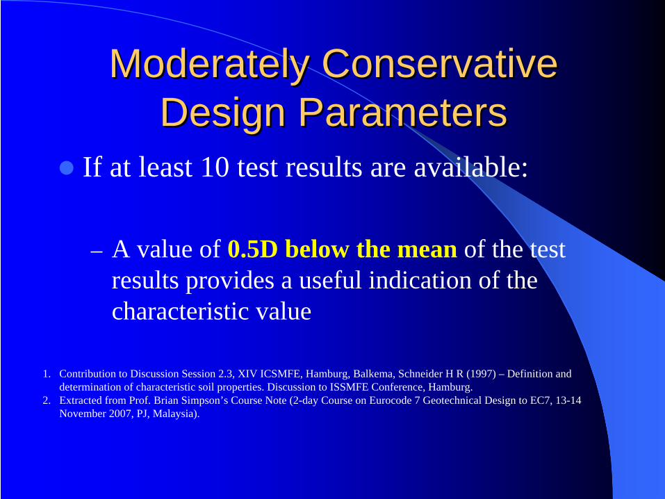
Moderately Conservative Moderately Conservative Design ParametersDesign Parameters
If at least 10 test results are available:
– A value of 0.5D below the mean of the test results provides a useful indication of the characteristic value
1. Contribution to Discussion Session 2.3, XIV ICSMFE, Hamburg, Balkema, Schneider H R (1997) – Definition and determination of characteristic soil properties. Discussion to ISSMFE Conference, Hamburg.
2. Extracted from Prof. Brian Simpson’s Course Note (2-day Course on Eurocode 7 Geotechnical Design to EC7, 13-14 November 2007, PJ, Malaysia).
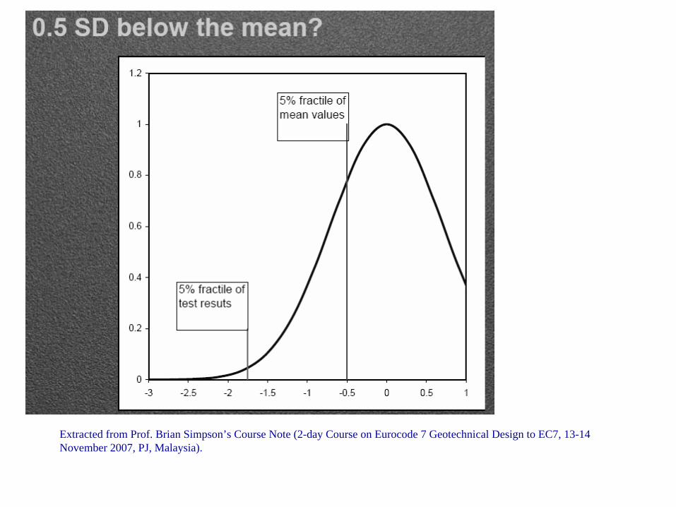
Extracted from Prof. Brian Simpson’s Course Note (2-day Course on Eurocode 7 Geotechnical Design to EC7, 13-14 November 2007, PJ, Malaysia).
•• Piles installed in a group may fail:Piles installed in a group may fail:• Individually
• As a block
Pile Capacity Design Pile Capacity Design Geotechnical CapacityGeotechnical Capacity
• Piles fail individually• When installed at large spacing
Pile Capacity Design Pile Capacity Design Geotechnical CapacityGeotechnical Capacity
• Piles fail as a block• When installed at close spacing
Pile Capacity Design Pile Capacity Design Geotechnical CapacityGeotechnical Capacity
Pile Capacity Design Pile Capacity Design Single Pile CapacitySingle Pile Capacity
Pile Capacity DesignPile Capacity Design Factor of Safety (FOS)Factor of Safety (FOS)
Factor of Safety (FOS) is required for
Natural variations in soil strength & variations in soil strength & compressibilitycompressibility
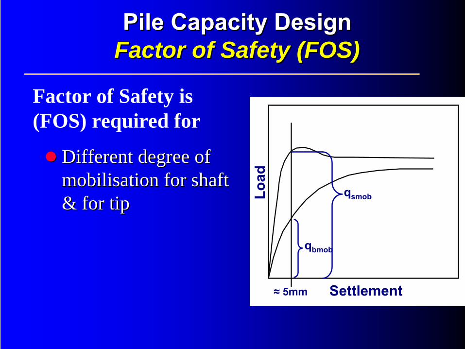
Pile Capacity DesignPile Capacity Design Factor of Safety (FOS)Factor of Safety (FOS)
Factor of Safety is (FOS) required for
Different degree of Different degree of mobilisationmobilisation for shaft for shaft & for tip& for tip Lo
ad
Settlement≈ 5mm
qsmob
qbmobLo
ad
Settlement≈ 5mm
qsmob
qbmob
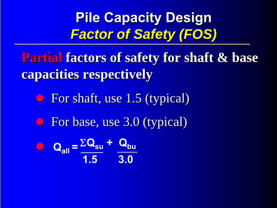
Pile Capacity Design Pile Capacity Design Factor of Safety (FOS)Factor of Safety (FOS)
PartialPartial factors of safety for shaft & base factors of safety for shaft & base capacities respectivelycapacities respectively
For shaft, use 1.5 (typical)For shaft, use 1.5 (typical)
For base, use 3.0 (typical)For base, use 3.0 (typical)ΣQsu
+ Qbu
1.5 3.0Qall
=

Pile Capacity DesignPile Capacity Design Factor of Safety (FOS)Factor of Safety (FOS)
GlobalGlobal factor of safety for total ultimate factor of safety for total ultimate capacitycapacity
Use 2.0 (typical)Use 2.0 (typical)
ΣQsu
+ Qbu
2.0Qall
=
Pile Capacity Design Pile Capacity Design Factor of Safety (FOS)Factor of Safety (FOS)
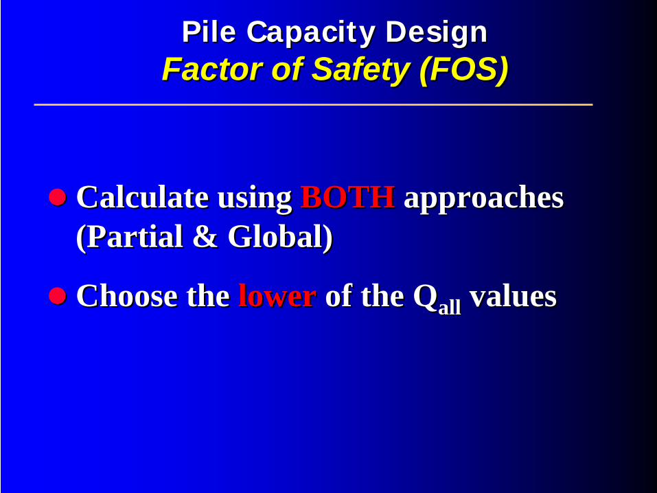
Calculate using Calculate using BOTHBOTH approaches approaches (Partial & Global)(Partial & Global)
Choose the Choose the lower lower of the of the QQallall valuesvalues
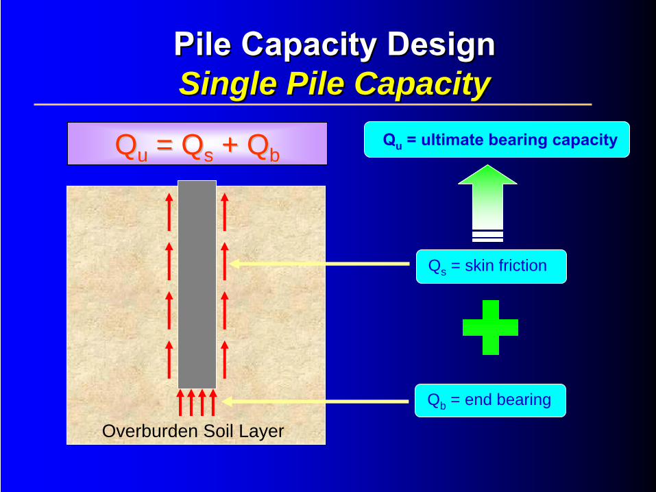
QQuu = Q= Qss + + QQbb
Overburden Soil Layer
Qs = skin friction
Qb = end bearing
Qu
= ultimate bearing capacity
Pile Capacity Design Pile Capacity Design Single Pile CapacitySingle Pile Capacity
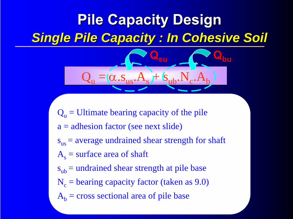
Qu = α.sus .As + sub .Nc .Ab
Qsu Qbu
Qu = Ultimate bearing capacity of the pile a = adhesion factor (see next slide)sus = average undrained shear strength for shaftAs = surface area of shaft sub = undrained shear strength at pile baseNc = bearing capacity factor (taken as 9.0) Ab = cross sectional area of pile base
Pile Capacity Design Pile Capacity Design Single Pile Capacity : In Cohesive SoilSingle Pile Capacity : In Cohesive Soil
Pile Capacity DesignPile Capacity Design Single Pile Capacity:Single Pile Capacity: In Cohesive SoilIn Cohesive Soil
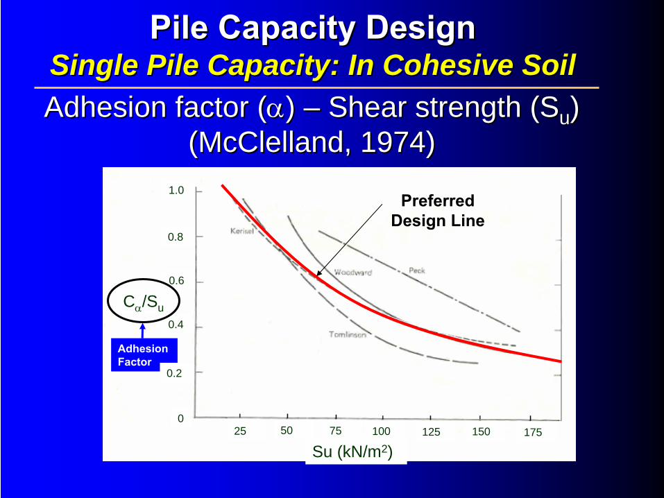
Adhesion factor (Adhesion factor (αα) ) –– Shear strength (SShear strength (Suu ) ) (McClelland, 1974)(McClelland, 1974)
Adhesion Factor
Su (kN/m2)25 75 100 125 150 17550
0
0.6
0.2
0.4
0.8
1.0
Cα
/Su
Preferred Design Line

Meyerhof Fukuoka
SPT N fsu =2.5N (kPa)
su = (0.1+0.15N)*50
(kPa)α
fsu =α.su (kPa)
0 0 5 1 5
1 2.5 12.5 1 12.5
5 12.5 42.5 0.7 29.75
10 25 80 0.52 41.6
15 37.5 117.5 0.4 47
20 50 155 0.33 51.15
30 75 230 0.3 69
40 100 305 0.3 91.5

Correlation Between SPT N and Correlation Between SPT N and ff susufsu vs SPT N
0
10
20
30
40
50
60
70
80
90
100
110
0 5 10 15 20 25 30 35 40 45
SPT N
fsu
(kP
a)
Meyerhof Fukuoka
Pile Capacity DesignPile Capacity Design Single Pile Capacity:Single Pile Capacity: In Cohesive SoilIn Cohesive Soil
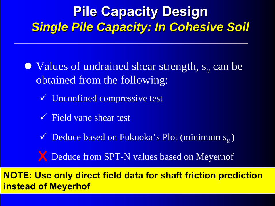
Values of undrained shear strength, su can be obtained from the following:
Unconfined compressive test
Field vane shear test
Deduce based on Fukuoka’s Plot (minimum su )
Deduce from SPT-N values based on Meyerhof
Pile Capacity DesignPile Capacity Design Single Pile Capacity:Single Pile Capacity: In Cohesive SoilIn Cohesive Soil
NOTE: Use only direct field data for shaft friction prediction instead of Meyerhof
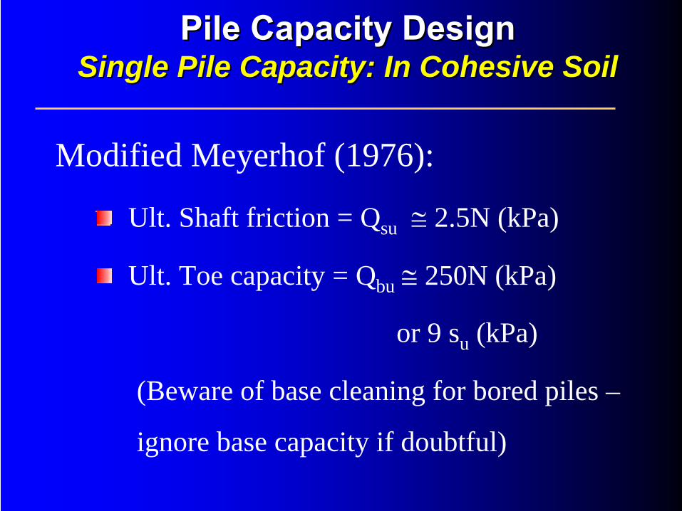
Modified Meyerhof (1976):
Ult. Shaft friction = Qsu ≅ 2.5N (kPa)
Ult. Toe capacity = Qbu ≅ 250N (kPa)
or 9 su (kPa)
(Beware of base cleaning for bored piles –
ignore base capacity if doubtful)
Pile Capacity DesignPile Capacity Design Single Pile Capacity:Single Pile Capacity: In Cohesive SoilIn Cohesive Soil
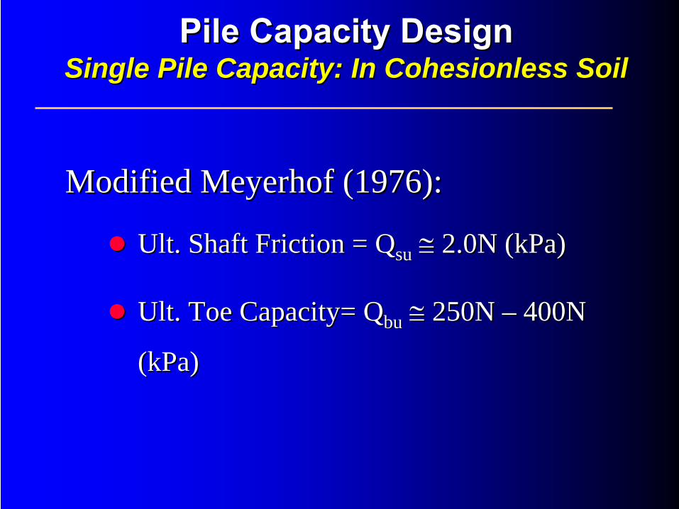
Modified Meyerhof (1976):Modified Meyerhof (1976):
UltUlt. Shaft Friction = . Shaft Friction = QQsusu ≅≅ 2.0N (2.0N (kPakPa))
UltUlt. Toe Capacity= . Toe Capacity= QQbubu ≅≅ 250N 250N –– 400N 400N
((kPakPa))
Pile Capacity DesignPile Capacity Design Single Pile Capacity:Single Pile Capacity: In In CohesionlessCohesionless SoilSoil
0 200 400 600
20
16
12
8
4
0
Dep
th (m
)
0 100 200 300 400 500Load (kN)
20
16
12
8
4
0
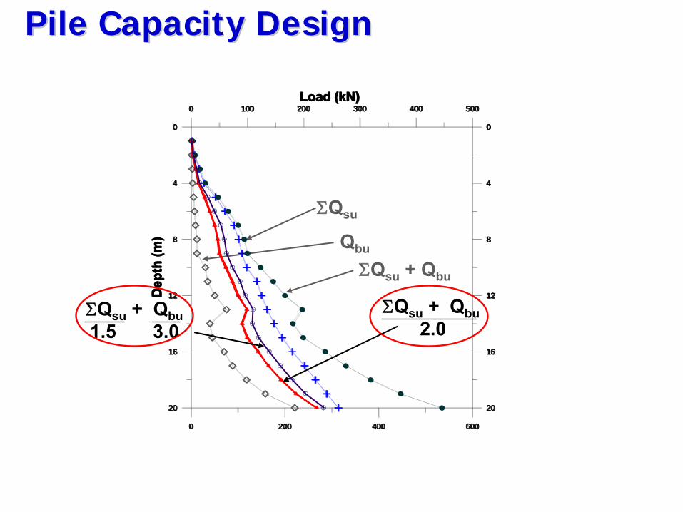
Pile Capacity DesignPile Capacity Design
ΣQsu
Qbu
ΣQsu
+ Qbu
0 200 400 600
20
16
12
8
4
0
Dep
th (m
)
0 100 200 300 400 500Load (kN)
20
16
12
8
4
0
0 200 400 600
20
16
12
8
4
0
Dep
th (m
)
0 100 200 300 400 500Load (kN)
20
16
12
8
4
0
0 200 400 600
20
16
12
8
4
0
Dep
th (m
)
0 100 200 300 400 500Load (kN)
20
16
12
8
4
0
ΣQsu
+ Qbu2.0
0 200 400 600
20
16
12
8
4
0
Dep
th (m
)
0 100 200 300 400 500Load (kN)
20
16
12
8
4
0
ΣQsu
+ Qbu1.5 3.0

SemiSemi--empirical Method (SPTempirical Method (SPT--N)N)Shaft : Shaft : ffsusu = = KKsusu ××
SPTSPT--NNTip Tip : : ffbubu = = KKbubu ××
SPTSPT--NN
From Malaysian experience:From Malaysian experience:
KKsusu = 2.0= 2.0KKbubu = 7.0 to 60 (depending on workmanship)= 7.0 to 60 (depending on workmanship)
Pile Capacity DesignPile Capacity Design Single Pile Capacity:Single Pile Capacity: For Bored PilesFor Bored Piles
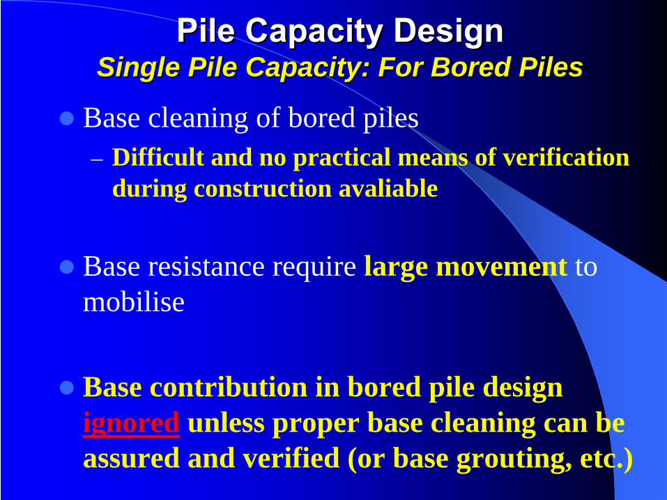
Base cleaning of bored piles– Difficult and no practical means of verification
during construction avaliable
Base resistance require large movement to mobilise
Base contribution in bored pile design ignored unless proper base cleaning can be assured and verified (or base grouting, etc.)
Pile Capacity DesignPile Capacity Design Single Pile Capacity:Single Pile Capacity: For Bored PilesFor Bored Piles
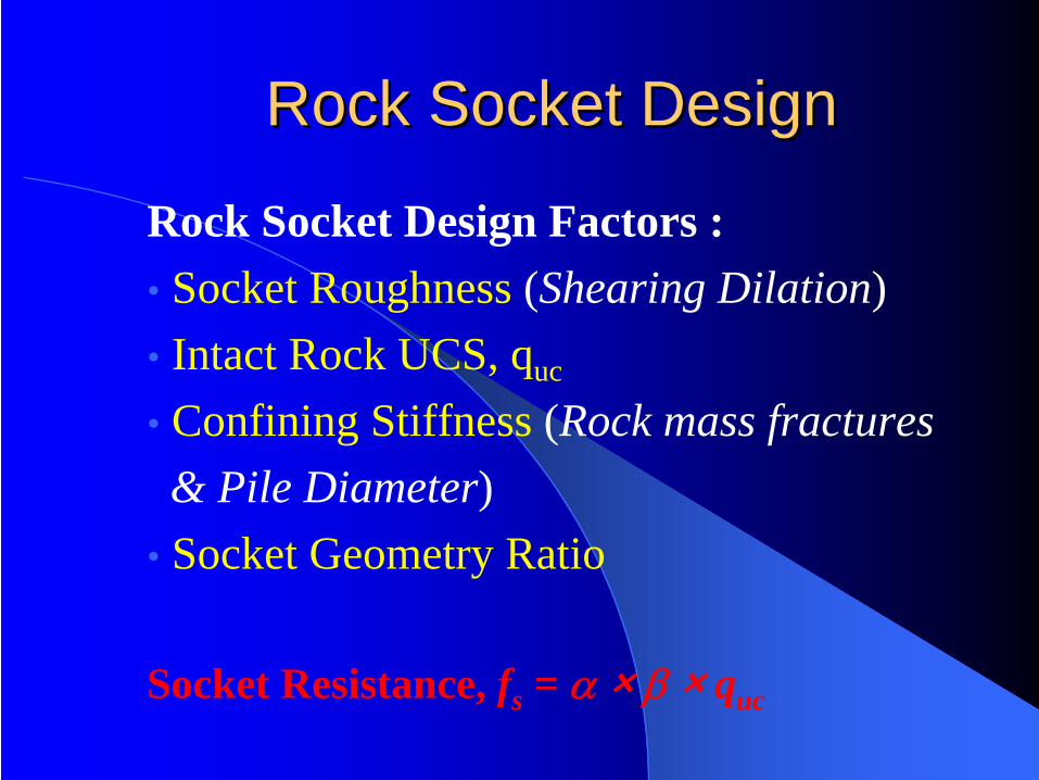
Rock Socket DesignRock Socket Design
Rock Socket Design Factors :• Socket Roughness (Shearing Dilation)• Intact Rock UCS, quc
• Confining Stiffness (Rock mass fractures& Pile Diameter)
• Socket Geometry Ratio
Socket Resistance, fs = α × β × quc
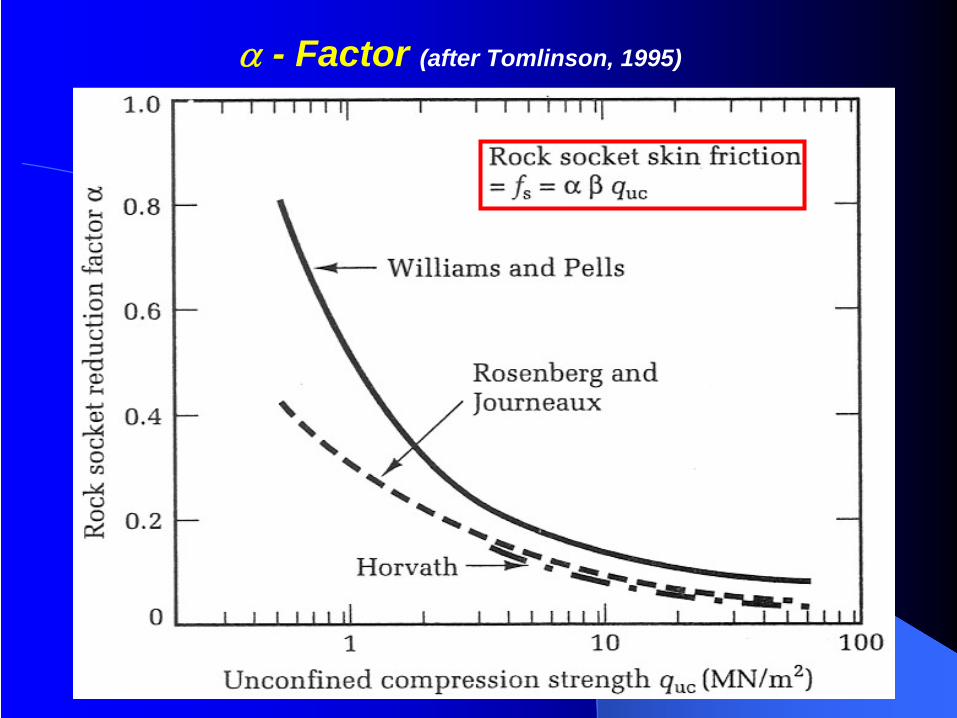
α - Factor (after Tomlinson, 1995)
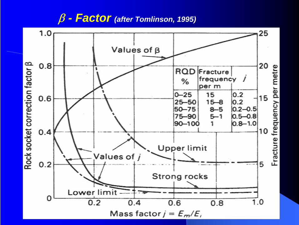
β - Factor (after Tomlinson, 1995)
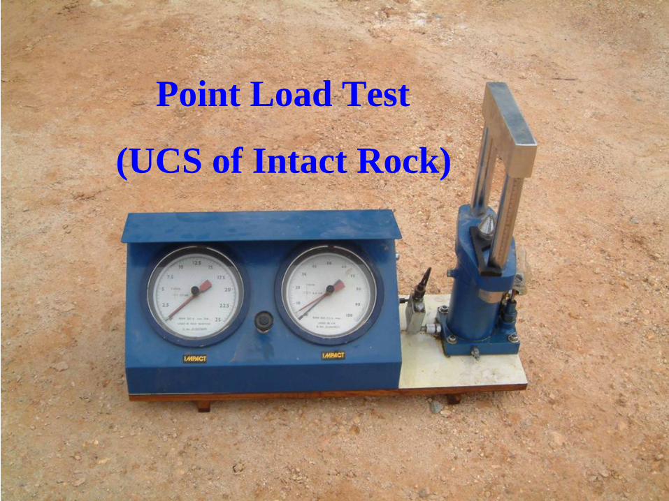
Point Load Test
(UCS of Intact Rock)
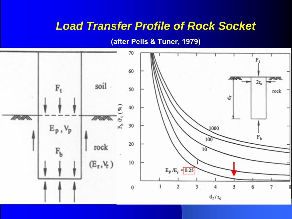
Load Transfer Profile of Rock Socket(after Pells
& Tuner, 1979)
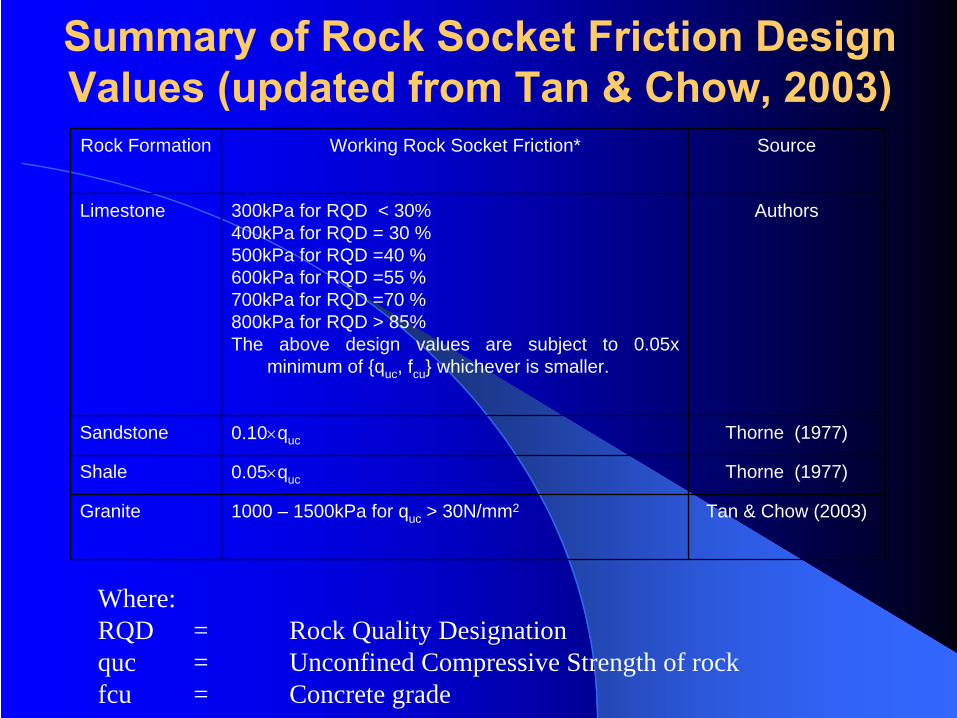
Summary of Rock Socket Friction Design Values (updated from Tan & Chow, 2003)
Rock Formation Working Rock Socket Friction* Source
Limestone 300kPa for RQD < 30%400kPa for RQD = 30 %500kPa for RQD =40 %600kPa for RQD =55 %700kPa for RQD =70 %800kPa for RQD > 85%The above design values are subject to 0.05x
minimum of {quc , fcu } whichever is smaller.
Authors
Sandstone 0.10×quc Thorne (1977)
Shale 0.05×quc Thorne (1977)
Granite 1000 – 1500kPa for quc > 30N/mm2 Tan & Chow (2003)
Where:RQD = Rock Quality Designationquc = Unconfined Compressive Strength of rockfcu = Concrete grade
End Bearing Design in RockEnd Bearing Design in Rock
Only designed when • Dry Hole• Base Cleaning & Inspection are possible
Pile Capacity Design Pile Capacity Design Block CapacityBlock Capacity
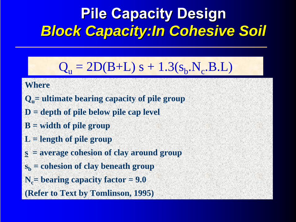
Qu = 2D(B+L) s + 1.3(sb .Nc .B.L)Where Qu = ultimate bearing capacity of pile groupD = depth of pile below pile cap levelB = width of pile groupL = length of pile groups = average cohesion of clay around groupsb = cohesion of clay beneath groupNc = bearing capacity factor = 9.0 (Refer to Text by Tomlinson, 1995)
Pile Capacity DesignPile Capacity Design Block Block Capacity:InCapacity:In Cohesive SoilCohesive Soil
No risk of group failure
if FOS of individual pile is adequate
Pile Capacity DesignPile Capacity Design Block Capacity:Block Capacity: In In CohesionlessCohesionless SoilSoil
No risk of block failure
if the piles are properly seated in the rock
formation
Pile Capacity DesignPile Capacity Design Block Capacity:Block Capacity: On RockOn Rock
Pile Capacity Design Pile Capacity Design Negative Skin Friction (NSF)Negative Skin Friction (NSF)
Compressible soil layer consolidates with time due to:
Surcharge of fillLowering of groundwater table
Pile Capacity DesignPile Capacity Design Negative Skin FrictionNegative Skin Friction
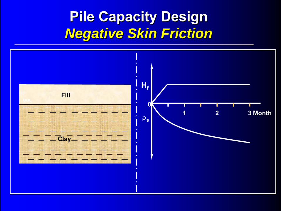
Clay
FillOGL
1 2 30
Hf
ρsMonth
Pile Capacity DesignPile Capacity Design Negative Skin FrictionNegative Skin Friction
Pile to length (floating pile)Pile settles with consolidating soil NO NSF
Pile Capacity DesignPile Capacity Design Negative Skin FrictionNegative Skin Friction
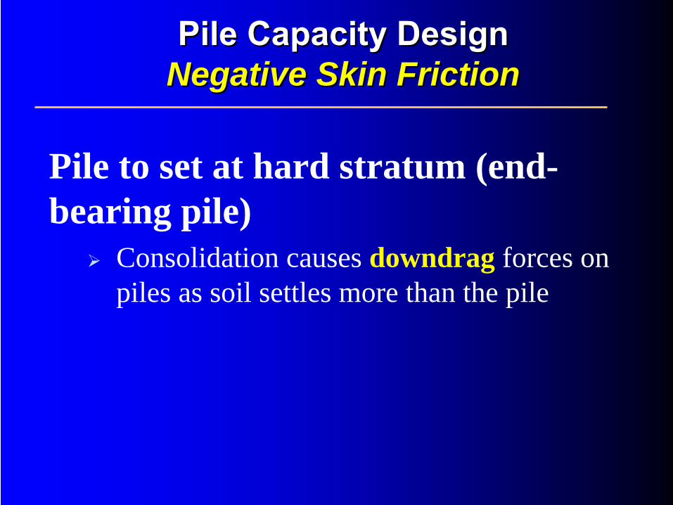
Pile to set at hard stratum (end- bearing pile)
Consolidation causes downdrag forces on piles as soil settles more than the pile
Pile Capacity DesignPile Capacity Design Negative Skin FrictionNegative Skin Friction
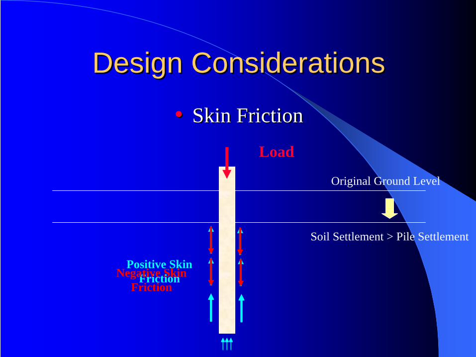
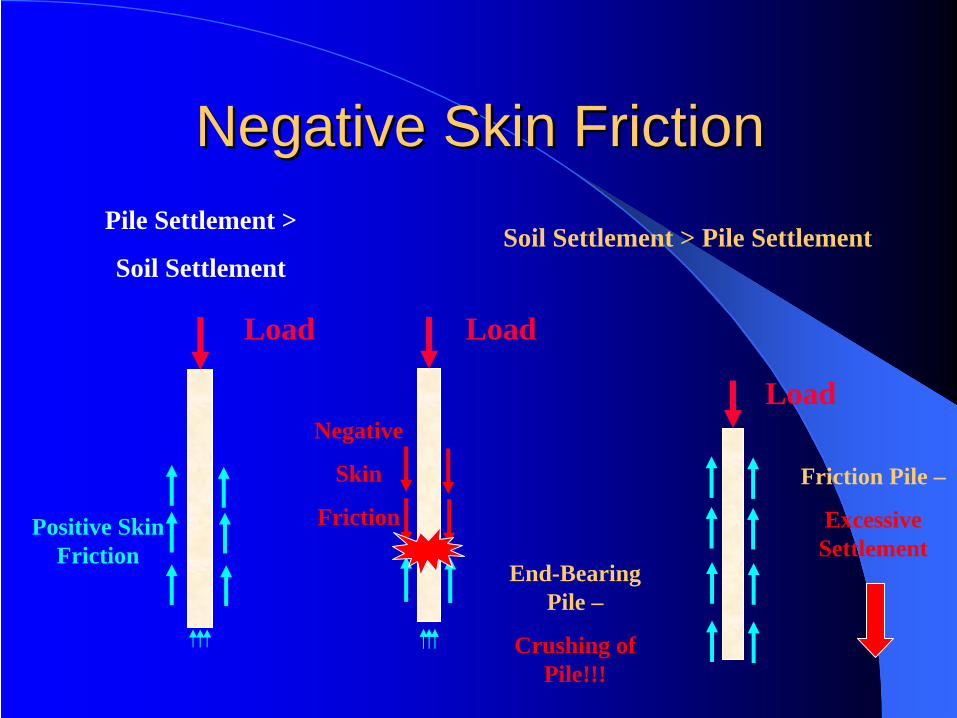
Design ConsiderationsDesign Considerations
•• Skin FrictionSkin FrictionLoad
Soil Settlement > Pile Settlement
Positive Skin FrictionNegative Skin
Friction
Original Ground Level
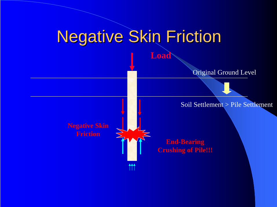
Negative Skin FrictionNegative Skin Friction
Soil Settlement > Pile Settlement
Load
Negative Skin Friction
Original Ground Level
End-Bearing Crushing of Pile!!!
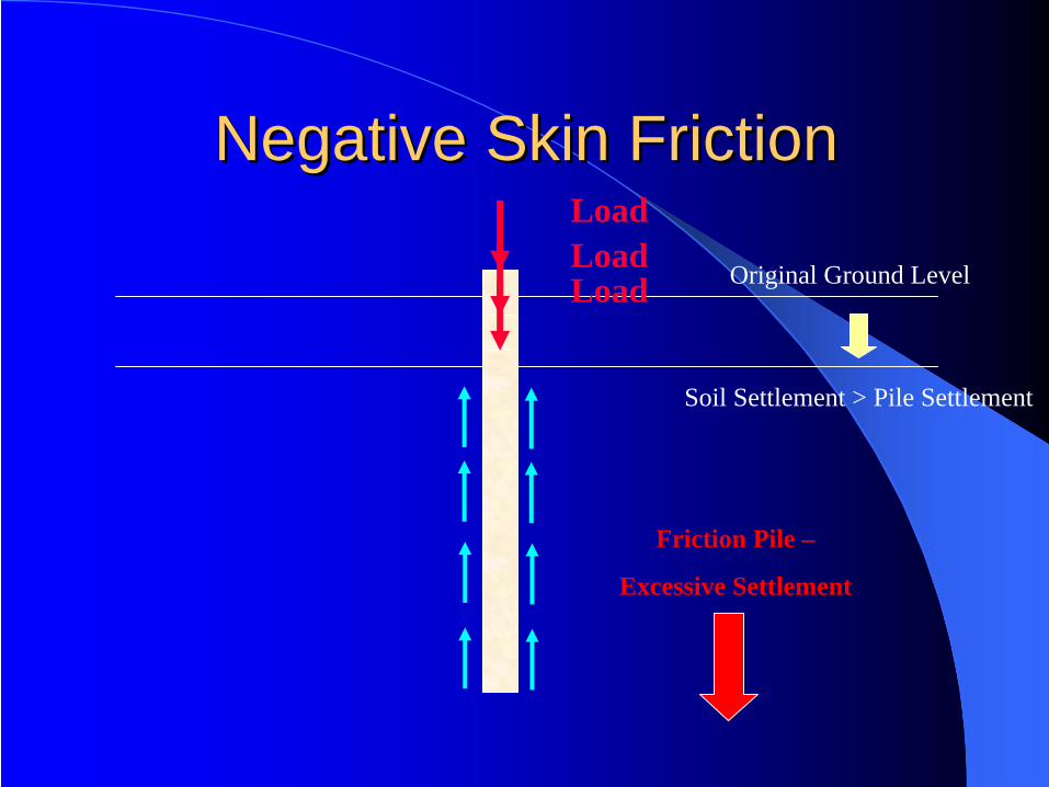
Negative Skin FrictionNegative Skin Friction
Soil Settlement > Pile Settlement
Load
Original Ground LevelLoadLoad
Friction Pile –
Excessive Settlement
Load
Load
Friction Pile –
Excessive Settlement
Load
End-Bearing Pile –
Crushing of Pile!!!
Positive Skin Friction
Pile Settlement >
Soil SettlementSoil Settlement > Pile Settlement
Negative Skin FrictionNegative Skin Friction
Negative
Skin
Friction

WARNING:No free fill by the contractor to avoid NSF
Pile Capacity DesignPile Capacity Design Negative Skin FrictionNegative Skin Friction
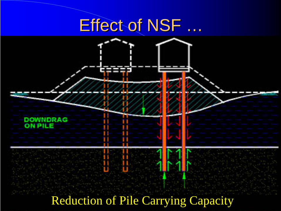
Effect of NSF Effect of NSF ……
Reduction of Pile Carrying Capacity
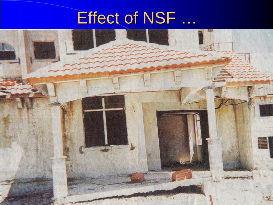
Effect of NSF Effect of NSF ……
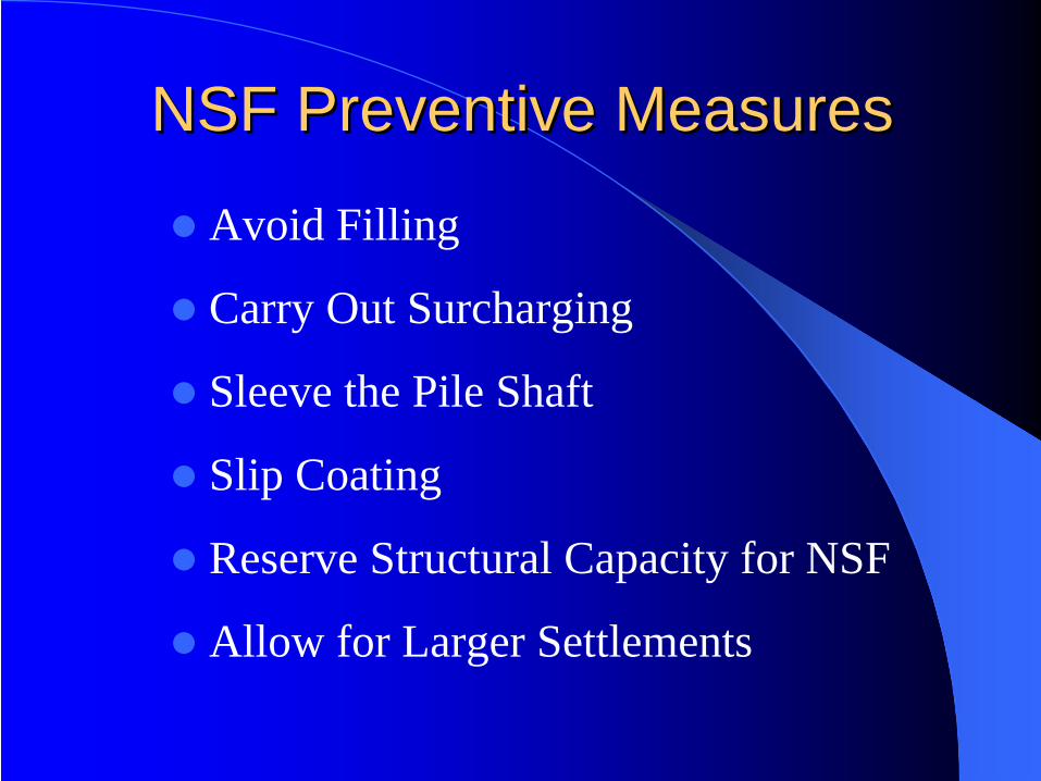
NSF Preventive MeasuresNSF Preventive Measures
Avoid Filling
Carry Out Surcharging
Sleeve the Pile Shaft
Slip Coating
Reserve Structural Capacity for NSF
Allow for Larger Settlements
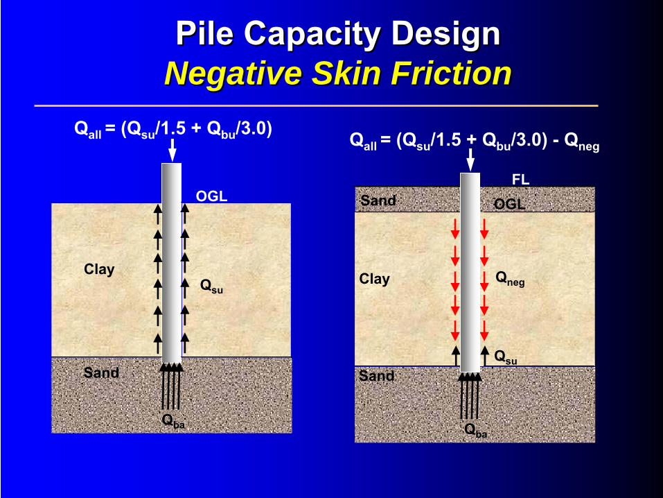
Clay
Sand
OGL
Qba
Qneg
SandFL
Clay
Sand
OGL
Qba
Qsu
Qall
= (Qsu
/1.5 + Qbu
/3.0) -
Qneg
Qsu
Qall
= (Qsu
/1.5 + Qbu
/3.0)
Pile Capacity DesignPile Capacity Design Negative Skin FrictionNegative Skin Friction
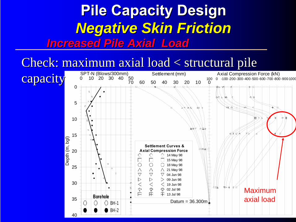
70 60 50 40 30 20 10 0
Settlement (mm)100 0 -100 -200-300-400-500-600 -700 -800 -900-1000
Axial Compression Force (kN)
Settlement Curves &Axial Compression Force
14 May 9815 May 9818 May 9821 May 9804 Jun 9809 Jun 9819 Jun 9802 Jul 9813 Jul 98
0 10 20 30 40 50SPT-N (Blows/300mm)
BoreholeBH-1BH-2
Datum = 36.300m
40
35
30
25
20
15
10
5
0
Dep
th (m
, bgl
)
Increased Pile Axial LoadIncreased Pile Axial Load
Check: maximum axial load < structural pile Check: maximum axial load < structural pile capacitycapacity
Pile Capacity Design Pile Capacity Design Negative Skin FrictionNegative Skin Friction
Maximum axial load

Allowable working loadQult
FOS
Pile Capacity DesignPile Capacity Design Factor of Safety (FOS)Factor of Safety (FOS)
Allowable working load
Qult
FOS(Qneg
+ etc)
Without Negative Skin Friction:
With Negative Skin Friction:
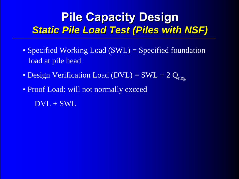
Pile Capacity DesignPile Capacity Design Static Pile Load Test (Piles with NSF)Static Pile Load Test (Piles with NSF)
• Specified Working Load (SWL) = Specified foundationload at pile head
• Design Verification Load (DVL) = SWL + 2 Qneg
• Proof Load: will not normally exceed
DVL + SWL
Pile Settlement DesignPile Settlement Design
Pile Settlement DesignPile Settlement Design In Cohesive SoilIn Cohesive Soil
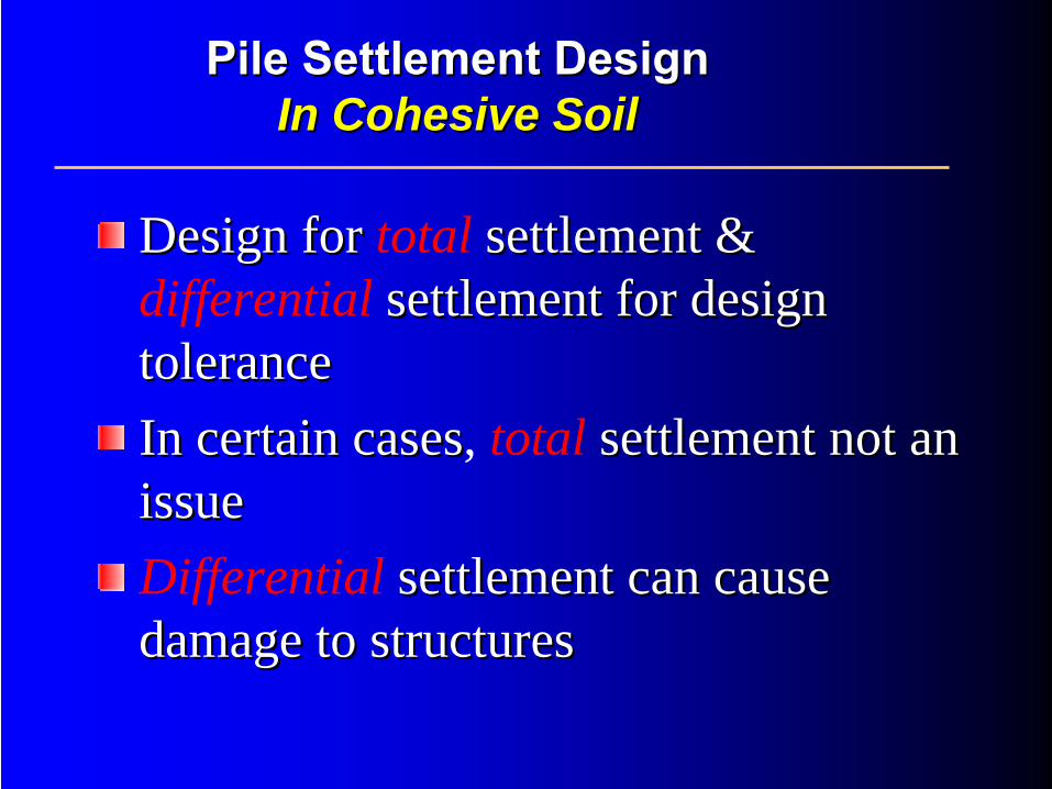
Design for Design for total settlement & settlement & differential settlement for design settlement for design tolerancetoleranceIn certain casesIn certain cases, total settlement not an settlement not an issueissueDifferential settlement can cause settlement can cause damage to structuresdamage to structures
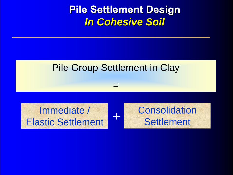
Pile Group Settlement in Clay
=
Immediate / Elastic Settlement + Consolidation
Settlement
Pile Settlement DesignPile Settlement Design In Cohesive SoilIn Cohesive Soil
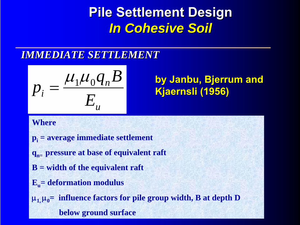
Where
pi = average immediate settlement
qn= pressure at base of equivalent raft
B = width of the equivalent raft
Eu = deformation modulus
μ1, μ0 = influence factors for pile group width, B at depth D
below ground surface
by by JanbuJanbu, , BjerrumBjerrum
and and KjaernsliKjaernsli
(1956)(1956)
IMMEDIATE SETTLEMENTIMMEDIATE SETTLEMENT
Pile Settlement DesignPile Settlement Design In Cohesive SoilIn Cohesive Soil
u
ni E
Bqp 01μμ=

μ1
μ0
Influence factors (after Janbu, Bjerrum and Kjaernsli, 1956)
IMMEDIATE SETTLEMENTIMMEDIATE SETTLEMENT
Pile Settlement DesignPile Settlement Design In Cohesive SoilIn Cohesive Soil
As per footing (references given later)
CONSOLIDATION SETTLEMENTCONSOLIDATION SETTLEMENT
Pile Settlement DesignPile Settlement Design In Cohesive SoilIn Cohesive Soil
No risk of excessive settlement
Pile Settlement DesignPile Settlement Design On RockOn Rock
Pile Installation Methods
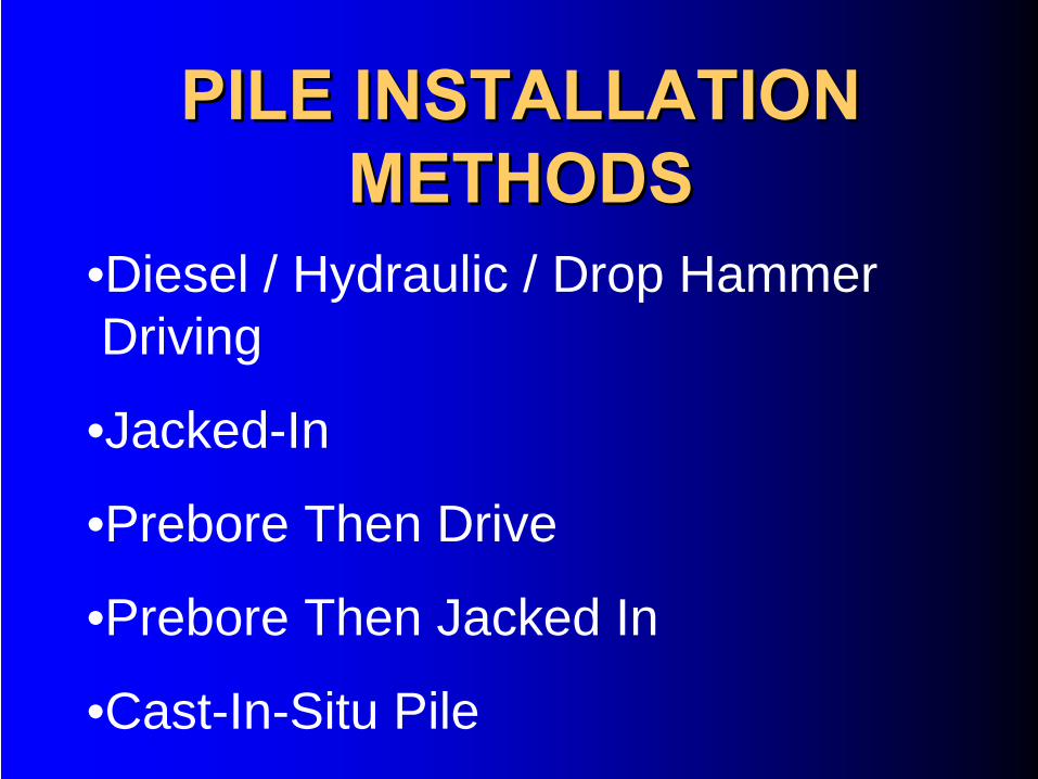
PILE INSTALLATION PILE INSTALLATION METHODSMETHODS
•Diesel / Hydraulic / Drop HammerDriving
•Jacked-In
•Prebore Then Drive
•Prebore Then Jacked In
•Cast-In-Situ Pile
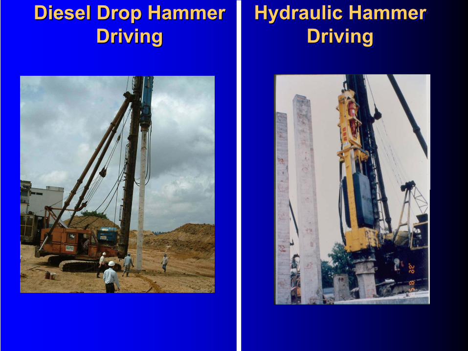
Diesel Drop Hammer Driving
Diesel Drop Hammer Diesel Drop Hammer DrivingDriving
Hydraulic Hammer Driving
Hydraulic Hammer Hydraulic Hammer DrivingDriving
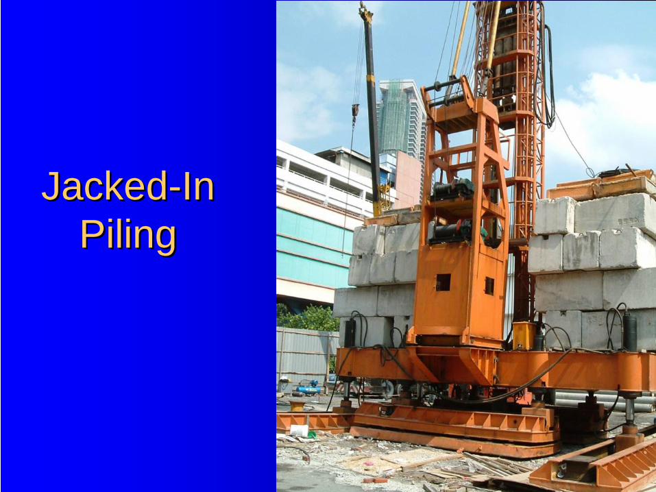
JackedJacked--In In PilingPiling
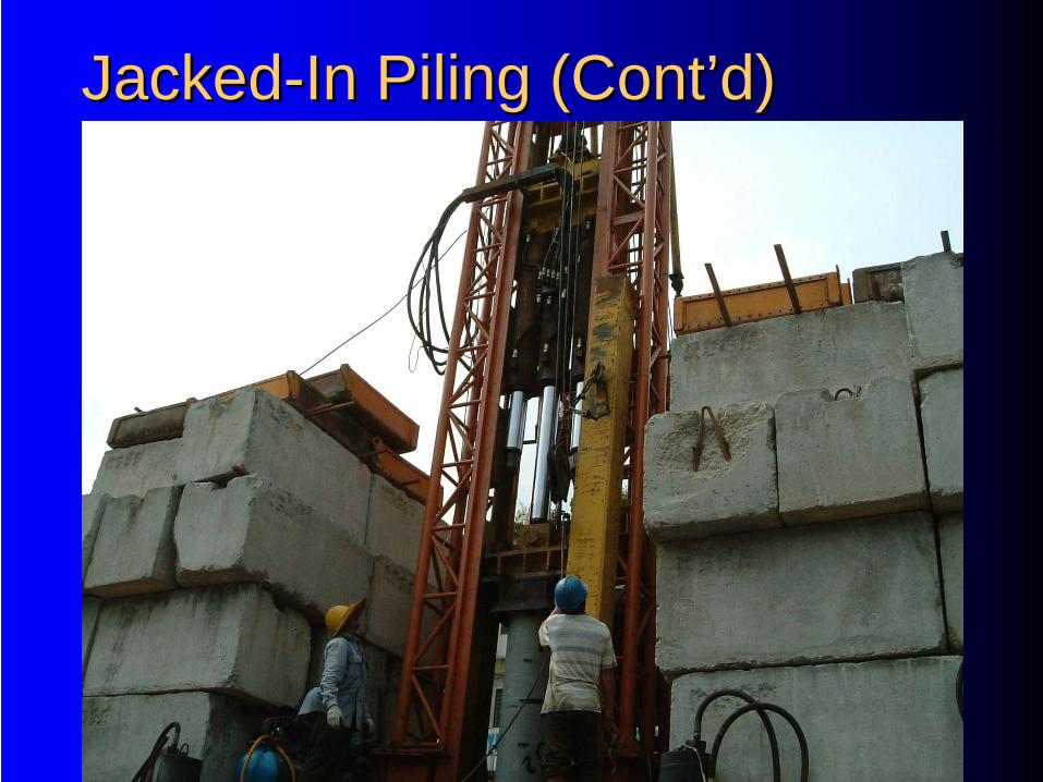
JackedJacked--In Piling (ContIn Piling (Cont’’d)d)
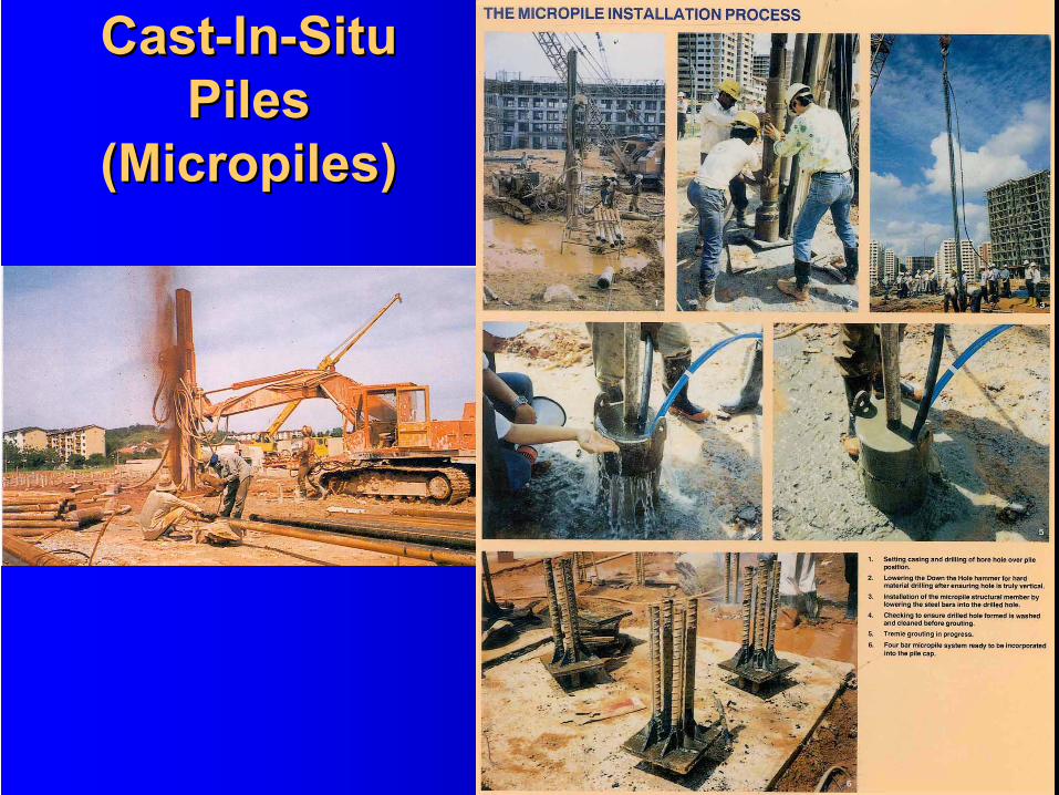
Cast-In-Situ Piles
(Micropiles)
CastCast--InIn--Situ Situ Piles Piles
((MicropilesMicropiles))

Types of Piles
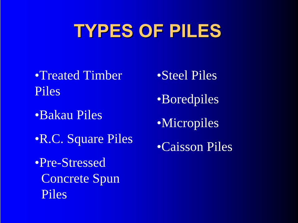
TYPES OF PILESTYPES OF PILES
•Treated Timber Piles
•Bakau Piles
•R.C. Square Piles
•Pre-Stressed Concrete SpunPiles
•Steel Piles
•Boredpiles
•Micropiles
•Caisson Piles
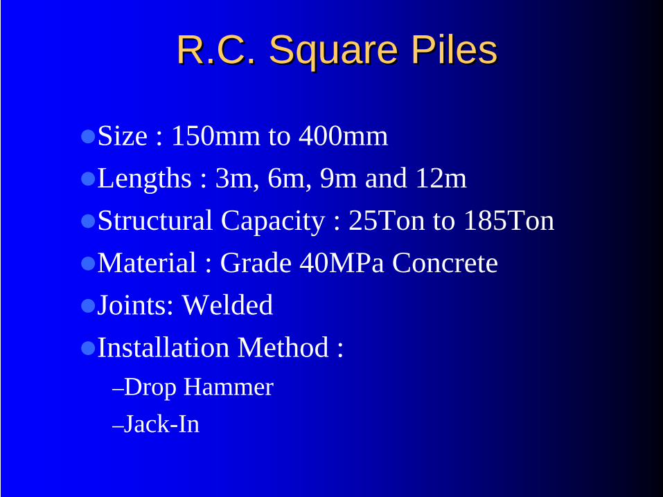
R.C. Square PilesR.C. Square Piles
Size : 150mm to 400mmLengths : 3m, 6m, 9m and 12mStructural Capacity : 25Ton to 185TonMaterial : Grade 40MPa ConcreteJoints: WeldedInstallation Method :
–Drop Hammer–Jack-In
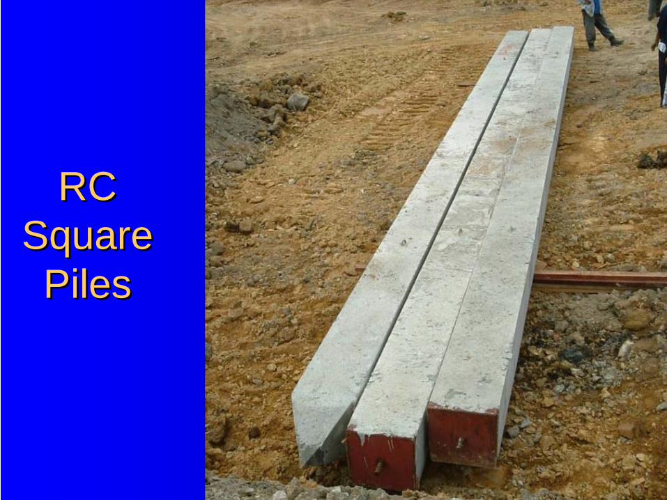
RC RC Square Square PilesPiles
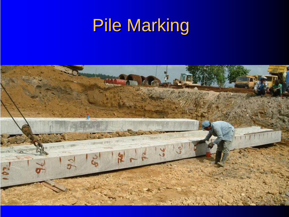
Pile MarkingPile Marking
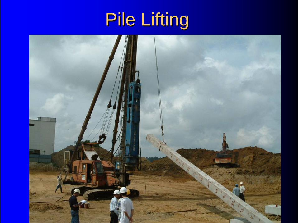
Pile LiftingPile Lifting
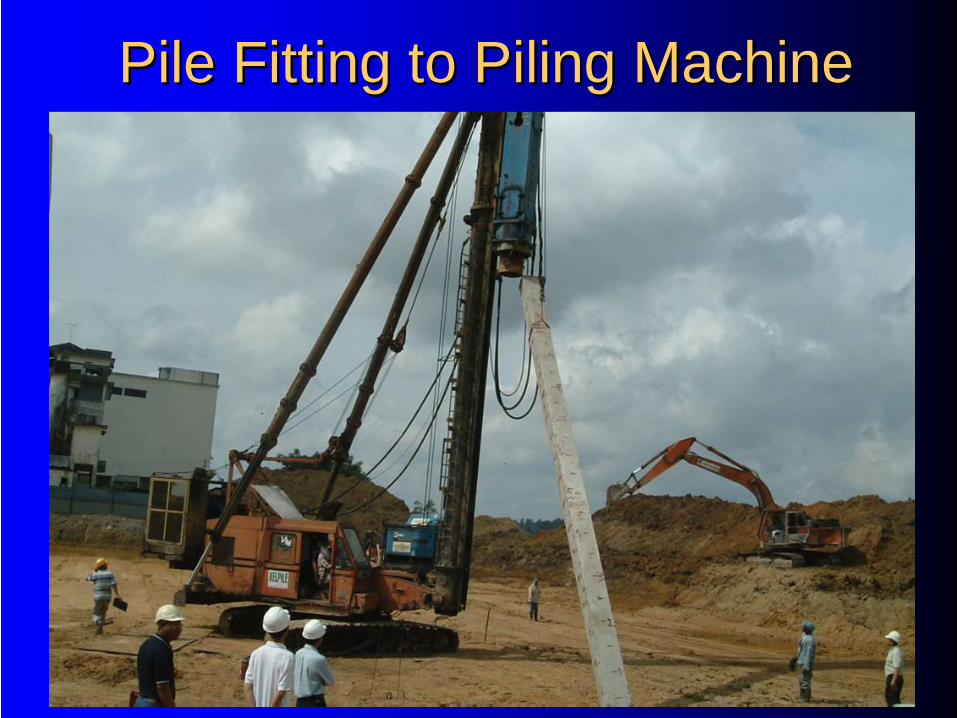
Pile Fitting to Piling MachinePile Fitting to Piling Machine

Pile Pile PositioningPositioning
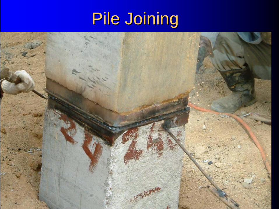
Pile JoiningPile Joining
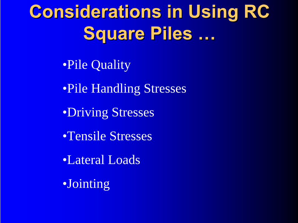
Considerations in Using RC Considerations in Using RC Square Piles Square Piles ……
•Pile Quality
•Pile Handling Stresses
•Driving Stresses
•Tensile Stresses
•Lateral Loads
•Jointing
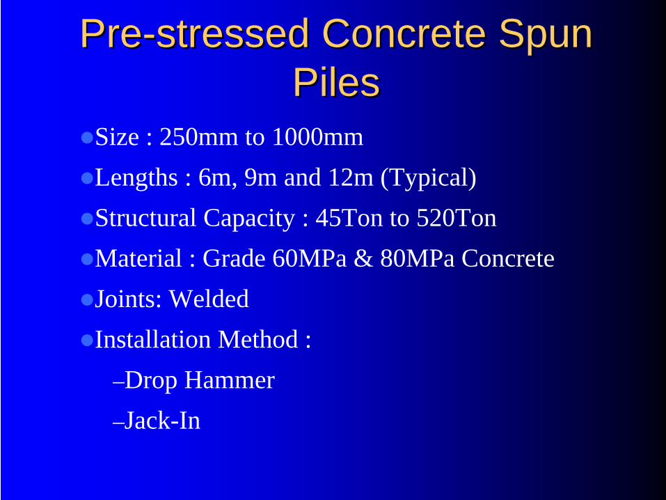
PrePre--stressed Concrete Spun stressed Concrete Spun PilesPiles
Size : 250mm to 1000mmLengths : 6m, 9m and 12m (Typical)Structural Capacity : 45Ton to 520TonMaterial : Grade 60MPa & 80MPa ConcreteJoints: WeldedInstallation Method :
–Drop Hammer–Jack-In
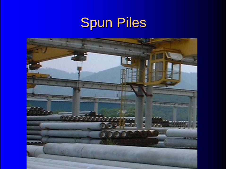
Spun PilesSpun Piles
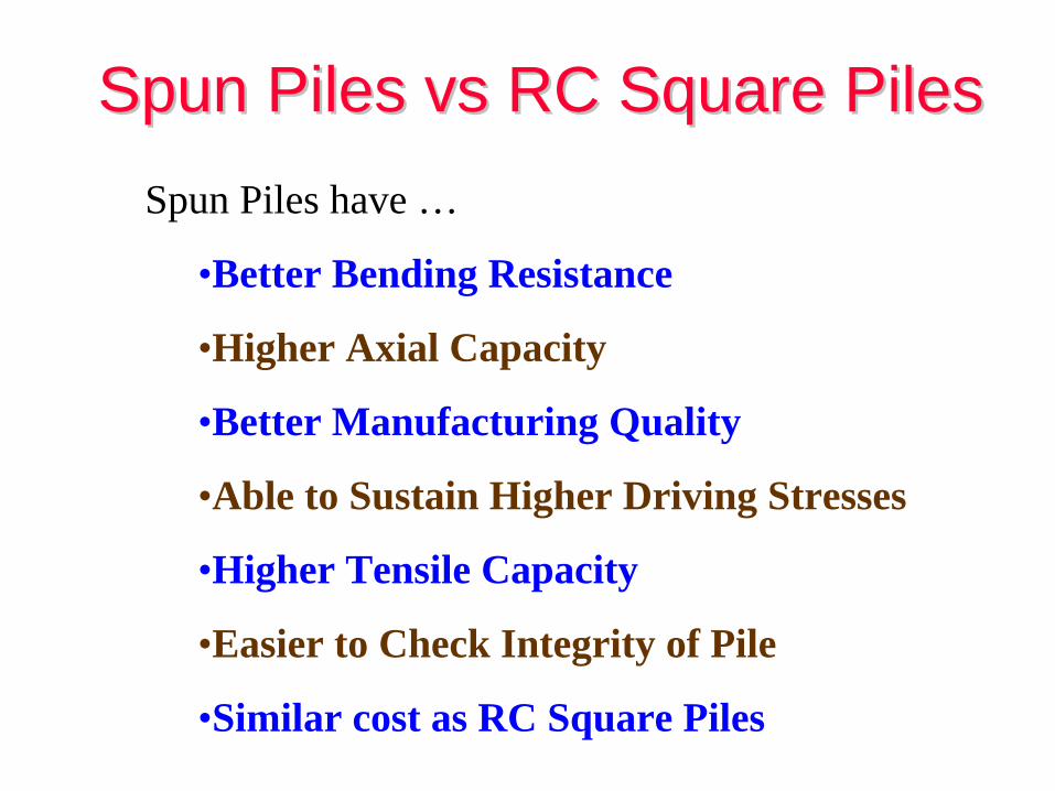
Spun Piles Spun Piles vsvs RC Square Piles RC Square Piles Spun Piles have …
•Better Bending Resistance
•Higher Axial Capacity
•Better Manufacturing Quality
•Able to Sustain Higher Driving Stresses
•Higher Tensile Capacity
•Easier to Check Integrity of Pile
•Similar cost as RC Square Piles
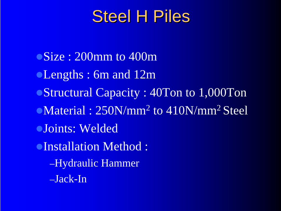
Steel H PilesSteel H Piles
Size : 200mm to 400mLengths : 6m and 12mStructural Capacity : 40Ton to 1,000TonMaterial : 250N/mm2 to 410N/mm2 SteelJoints: WeldedInstallation Method :
–Hydraulic Hammer–Jack-In
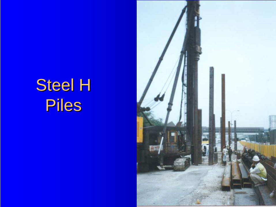
Steel H Steel H PilesPiles
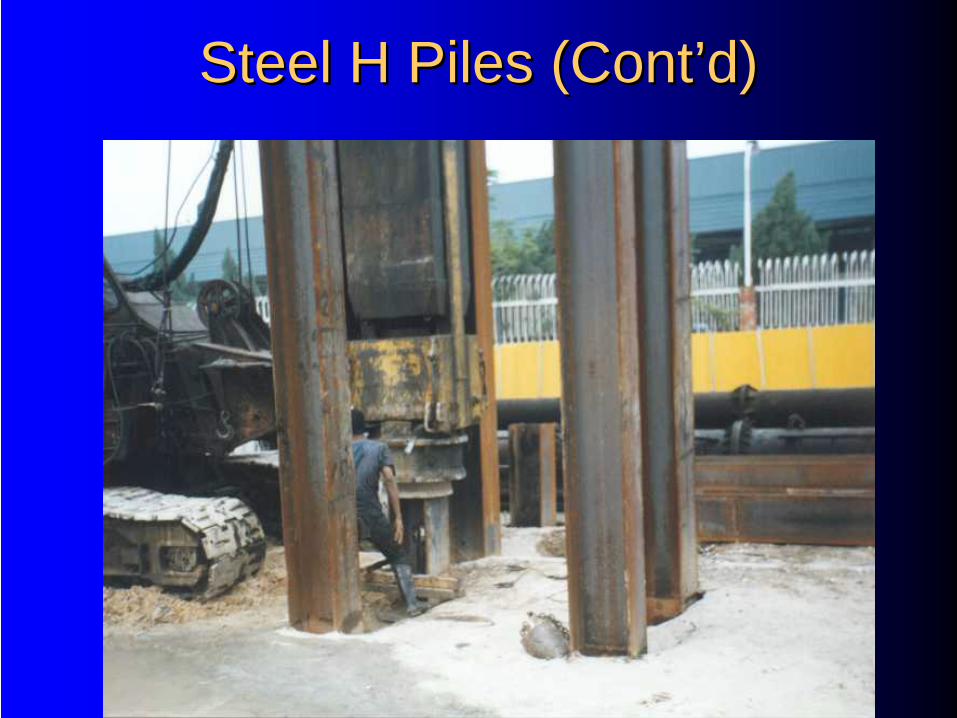
Steel H Piles (ContSteel H Piles (Cont’’d)d)
Steel H Piles NotesSteel H Piles Notes……
•Corrosion Rate
•Fatigue
•OverDriving
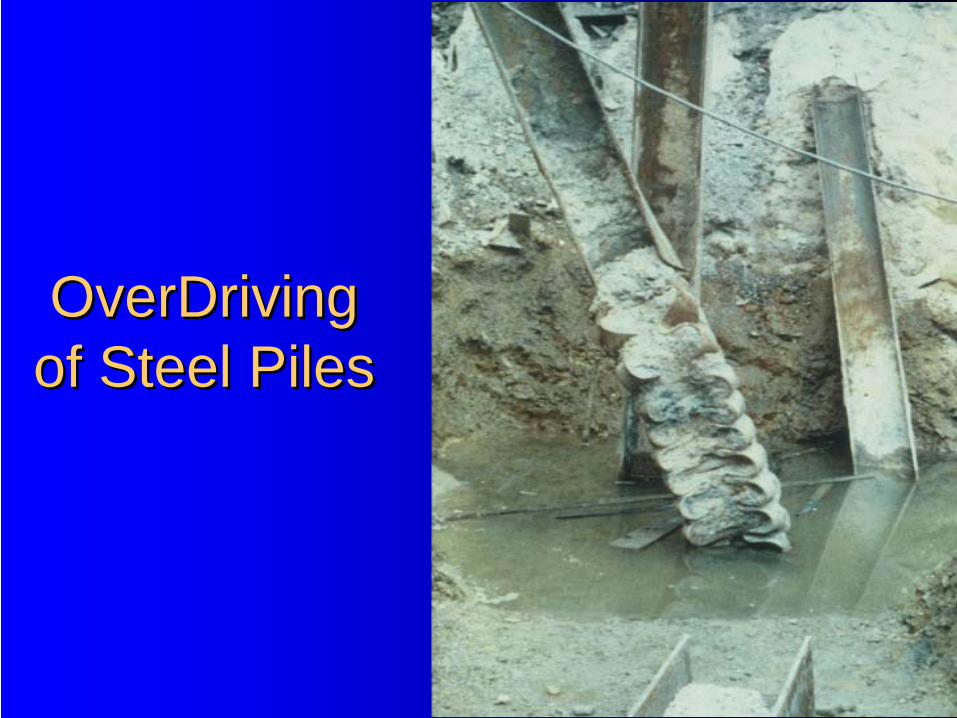
OverDrivingOverDriving of Steel Pilesof Steel Piles
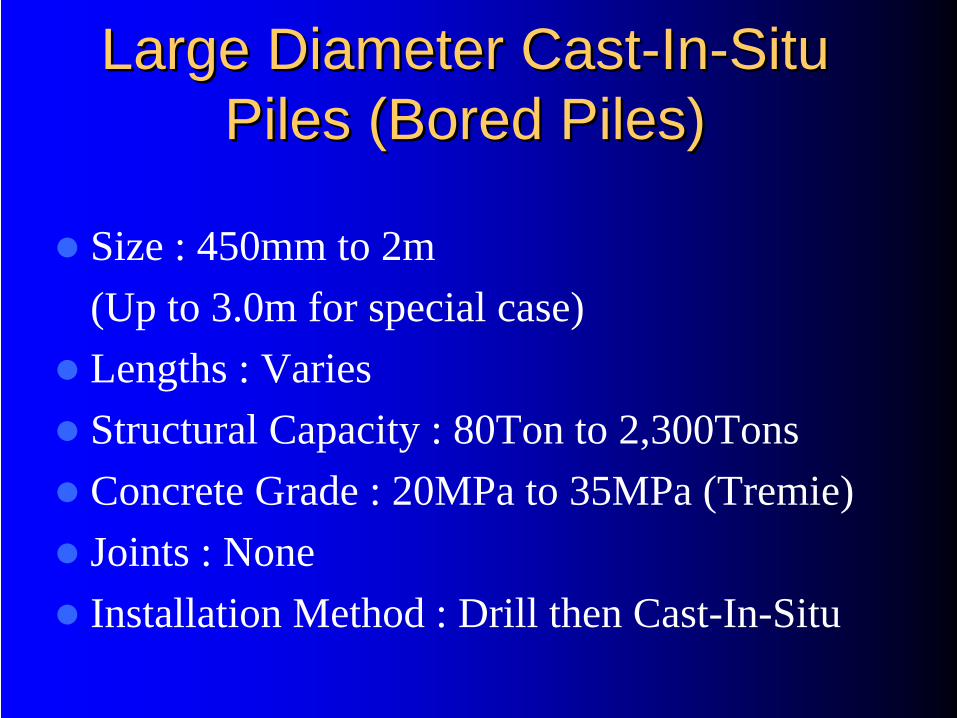
Large Diameter CastLarge Diameter Cast--InIn--Situ Situ Piles (Bored Piles)Piles (Bored Piles)
Size : 450mm to 2m (Up to 3.0m for special case)Lengths : VariesStructural Capacity : 80Ton to 2,300TonsConcrete Grade : 20MPa to 35MPa (Tremie)Joints : NoneInstallation Method : Drill then Cast-In-Situ
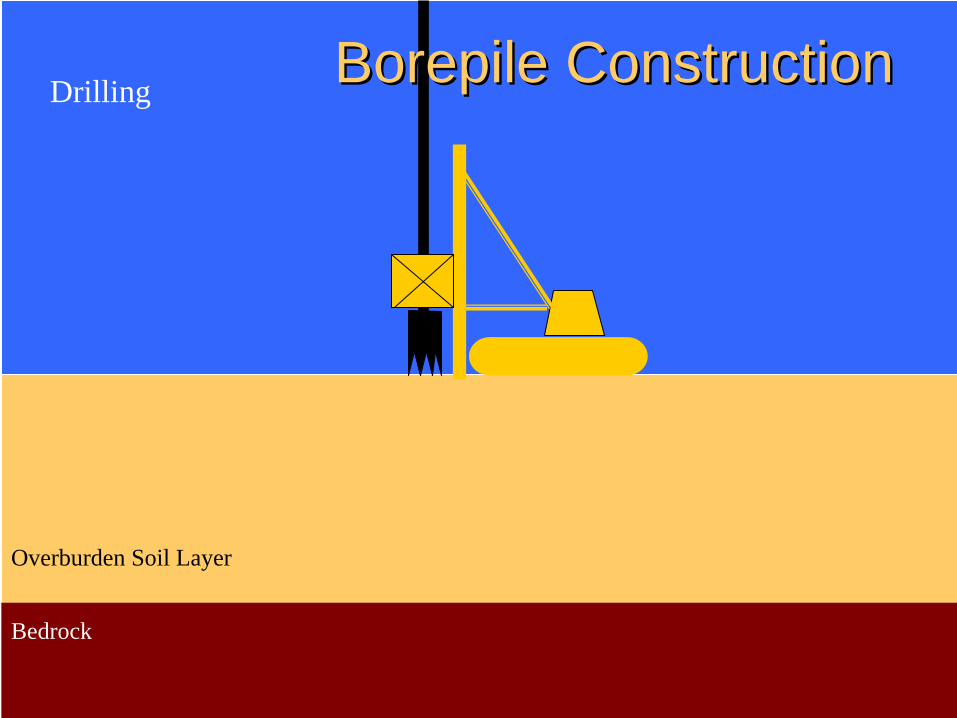
Overburden Soil Layer
Bedrock
Drilling BorepileBorepile ConstructionConstruction
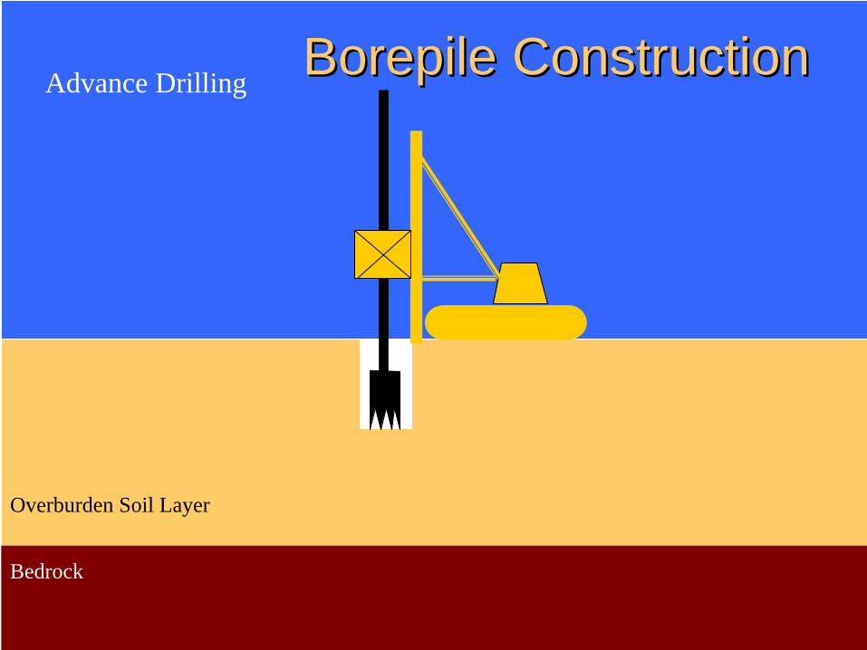
Overburden Soil Layer
Bedrock
Advance Drilling BorepileBorepile ConstructionConstruction
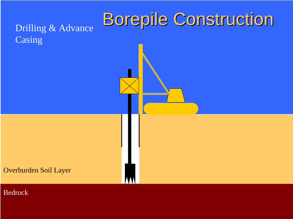
Overburden Soil Layer
Bedrock
Drilling & Advance Casing
BorepileBorepile ConstructionConstruction
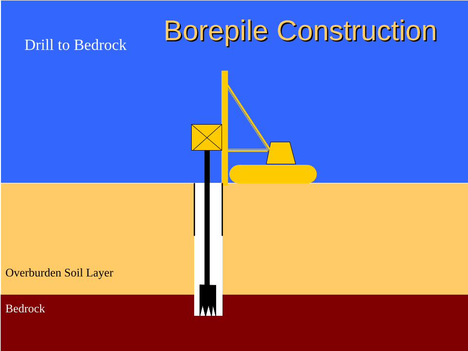
Overburden Soil Layer
Bedrock
Drill to Bedrock BorepileBorepile ConstructionConstruction
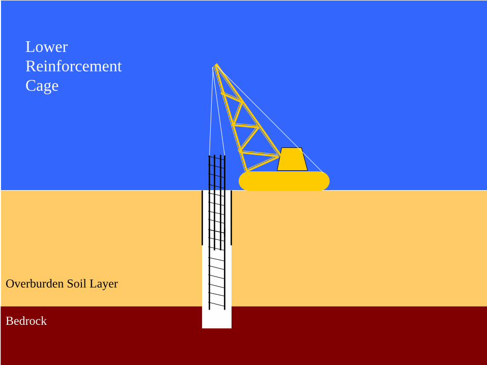
BorepileBorepile ConstructionConstruction
Overburden Soil Layer
Bedrock
Lower Reinforcement Cage
Overburden Soil Layer
Bedrock
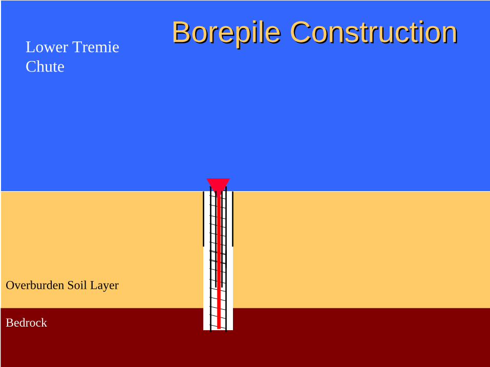
BorepileBorepile ConstructionConstructionLower Tremie Chute

Overburden Soil Layer
Bedrock
Pour Tremie Concrete
BorepileBorepile ConstructionConstruction
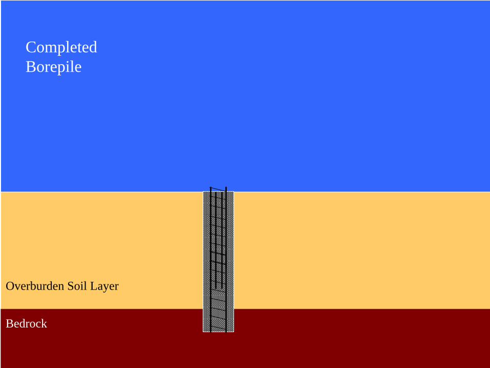
BorepileBorepile ConstructionConstruction
Overburden Soil Layer
Bedrock
Completed Borepile
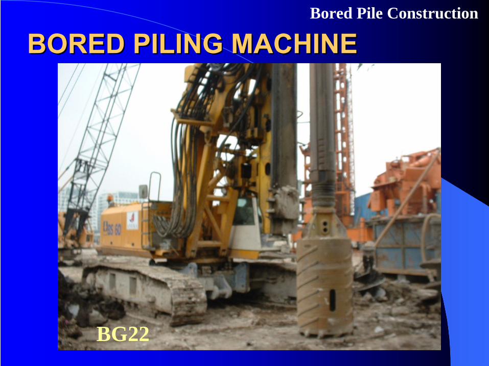
BORED PILING MACHINEBORED PILING MACHINEBored Pile Construction
BG22
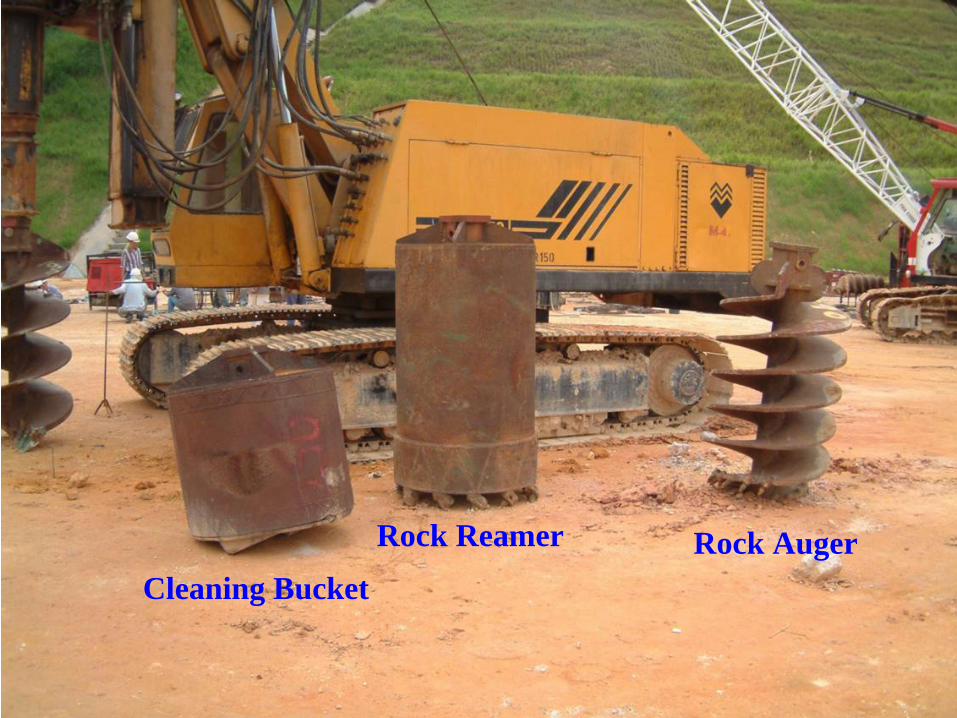
Cleaning Bucket
Rock Reamer Rock Auger
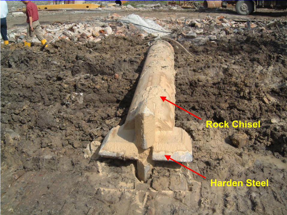
Harden Steel
Rock Chisel
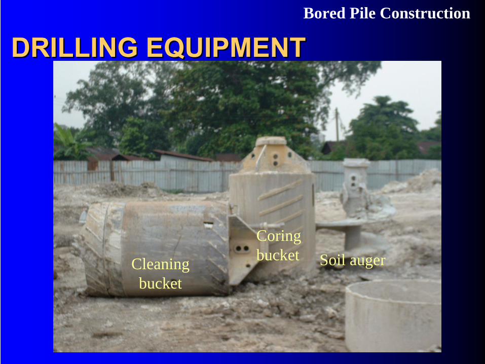
DRILLING EQUIPMENTDRILLING EQUIPMENTBored Pile Construction
Soil augerCoring bucketCleaning
bucket
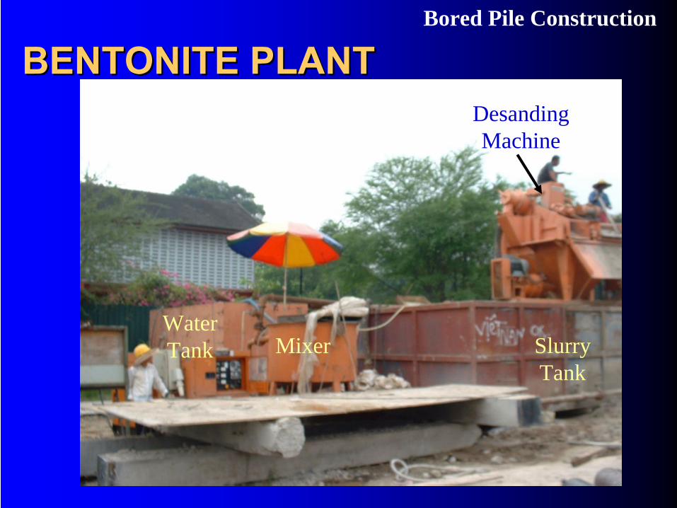
BENTONITE PLANTBENTONITE PLANTBored Pile Construction
MixerWater Tank Slurry
Tank
Desanding Machine
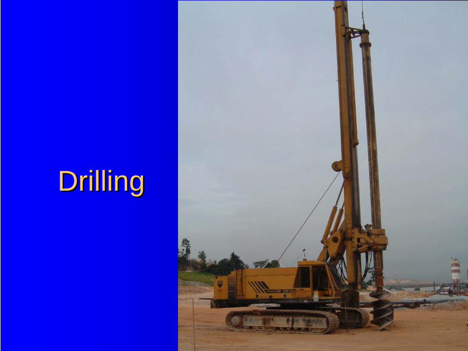
DrillingDrilling
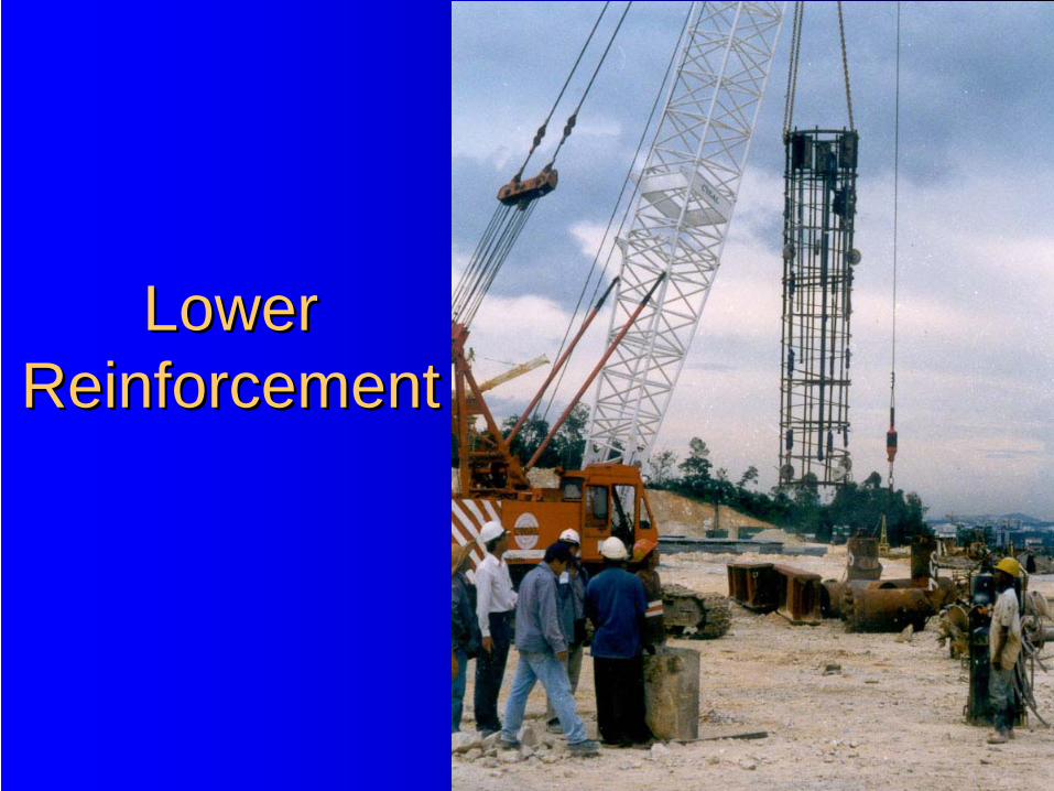
Lower Lower ReinforcementReinforcement
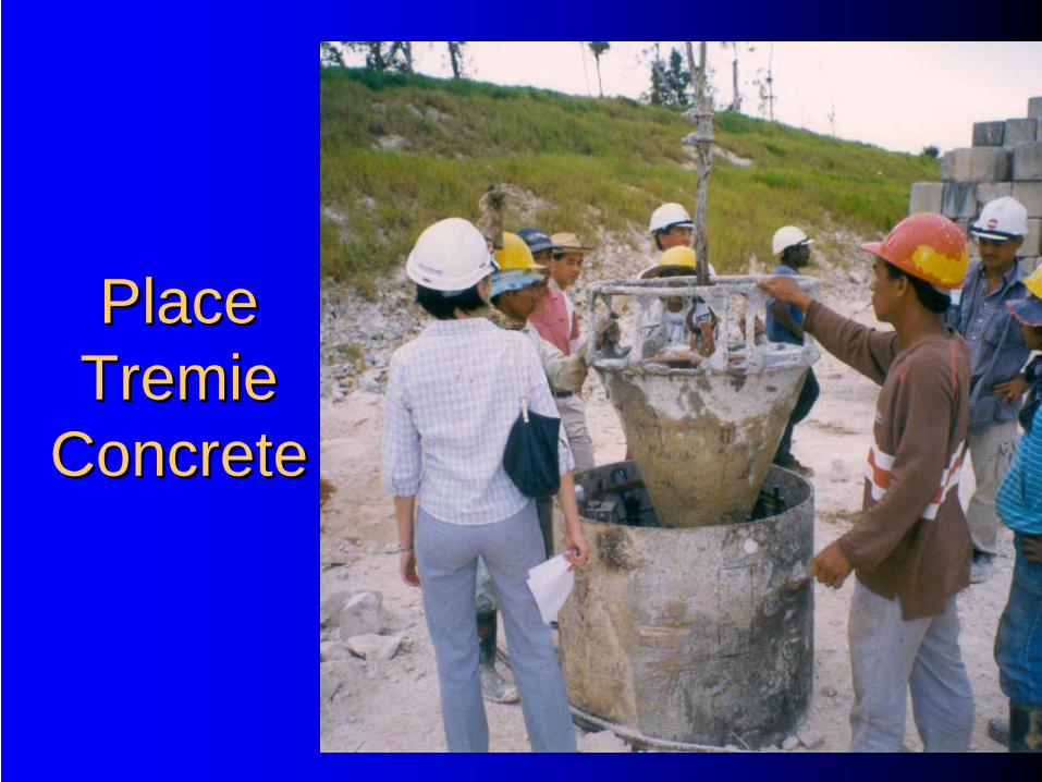
Place Place TremieTremie
ConcreteConcrete
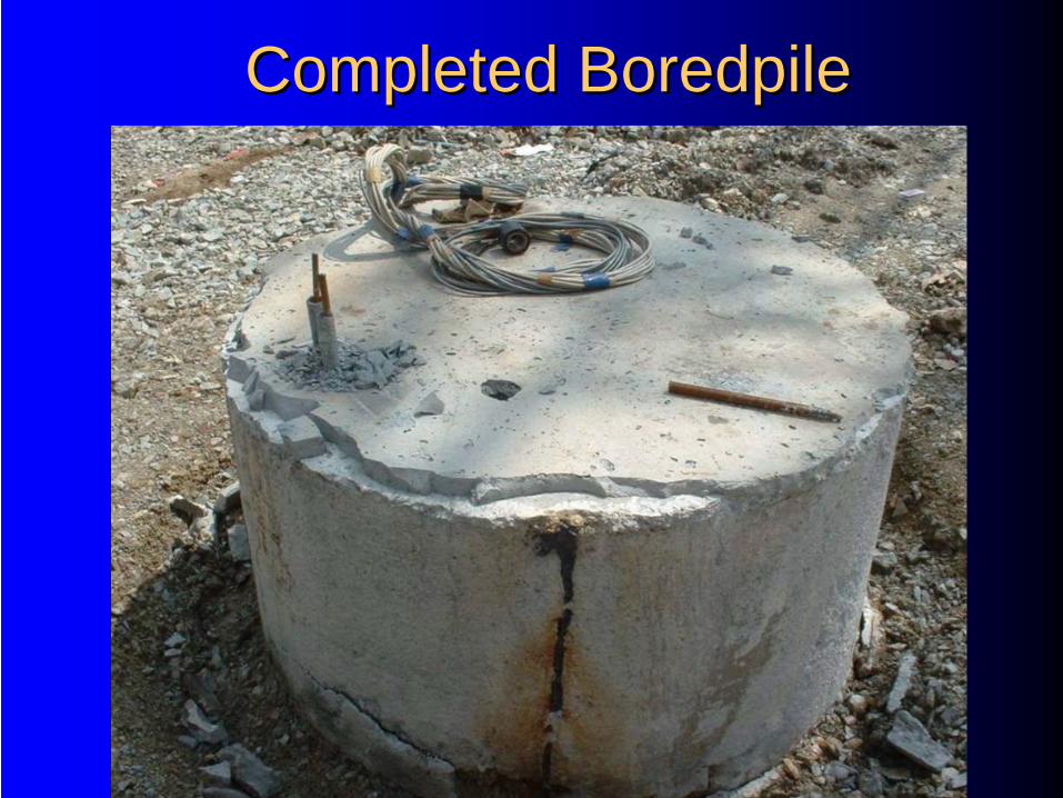
Completed Completed BoredpileBoredpile
BorepileBorepile CosiderationsCosiderations……
•Borepile Base Difficult to Clean
•Bulging / Necking
•Collapse of Sidewall
•Dispute on Level of Weathered Rock
MicropilesMicropiles
Size : 100mm to 350mm DiameterLengths : VariesStructural Capacity : 20Ton to 250TonMaterial : Grade 25MPa to 35MPa Grout
N80 API Pipe as ReinforcementJoints: NoneInstallation Method :
–Drill then Cast-In-Situ–Percussion Then Cast-In-Situ
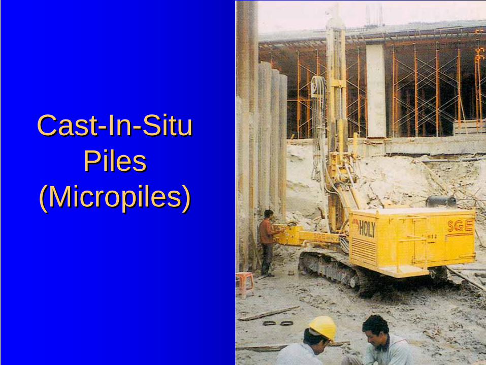
CastCast--InIn--Situ Situ PilesPiles
((MicropilesMicropiles))
TYPES OF PILE SHOESTYPES OF PILE SHOES
•Flat Ended Shoe
•Oslo Point
•Cast-Iron Pointed Tip
•Cross Fin Shoe
•H-Section
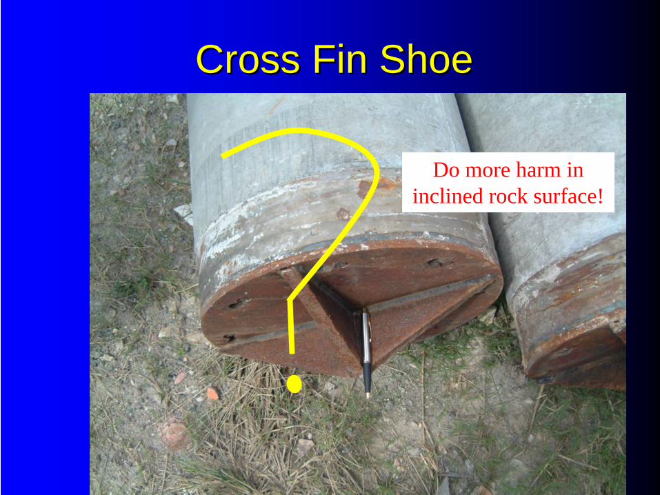
Cross Fin ShoeCross Fin Shoe
Do more harm in inclined rock surface!
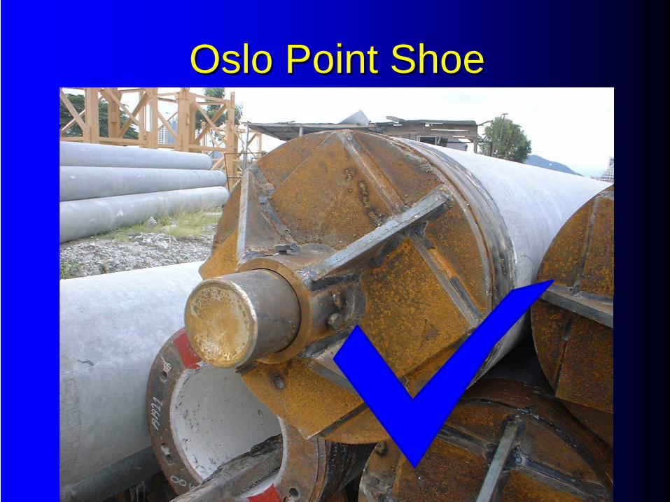
Oslo Point ShoeOslo Point Shoe
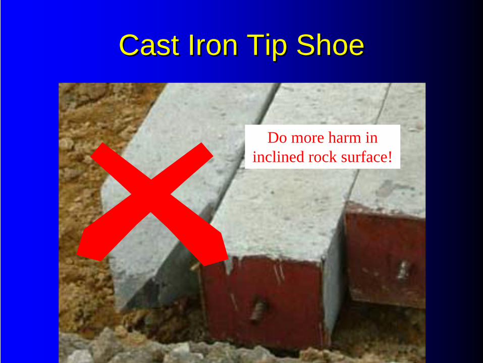
Cast Iron Tip ShoeCast Iron Tip Shoe
Do more harm in inclined rock surface!
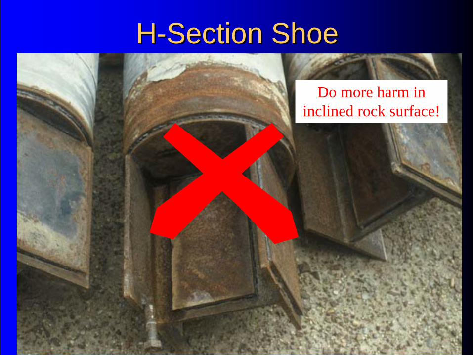
HH--Section ShoeSection Shoe
Do more harm in inclined rock surface!
Piling Supervision
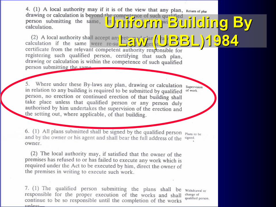
Uniform Building By Uniform Building By Law (UBBL)1984Law (UBBL)1984
PILING SUPERVISIONPILING SUPERVISION•Ensure That Piles Are Stacked Properly
•Ensure that Piles are Vertical During Driving
•Keep Proper Piling Records
•Ensure Correct Pile Types and Sizes are Used
•Ensure that Pile Joints are Properly Welded withNO GAPS
•Ensure Use of Correct Hammer Weights and DropHeights
PILING SUPERVISION PILING SUPERVISION (Cont(Cont’’d)d)
•Ensure that Proper Types of Pile Shoes are Used.
•Check Pile Quality
•Ensure that the Piles are Driven to the RequiredLengths
•Monitor Pile Driving
FAILURE OF PILING FAILURE OF PILING SUPERVISIONSUPERVISION
Failing to Provide Proper Supervision
WILL Result in
Higher Instances of Pile Damage
& Wastage
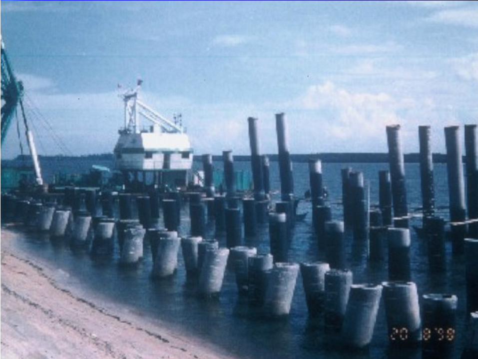
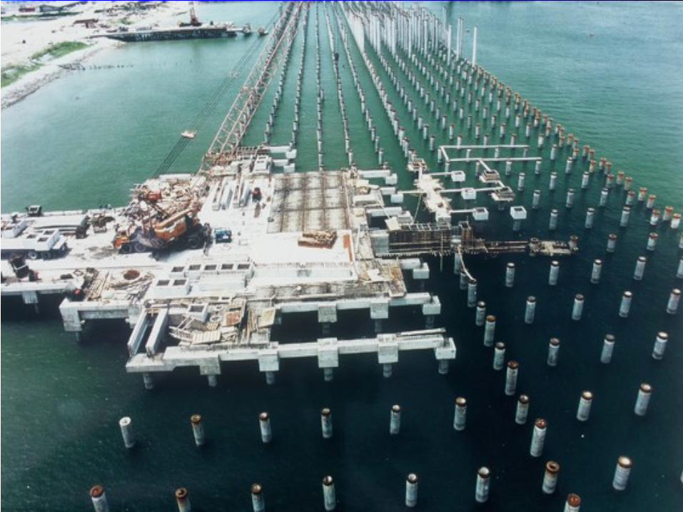
Pile Damage
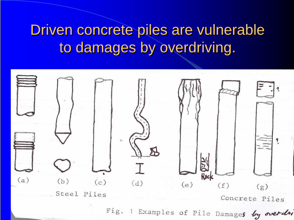
Driven concrete piles are vulnerable Driven concrete piles are vulnerable to damages by overdriving. to damages by overdriving.
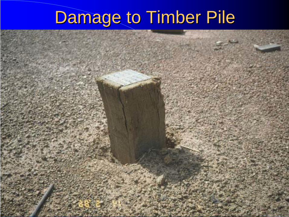
Damage to Timber PileDamage to Timber Pile
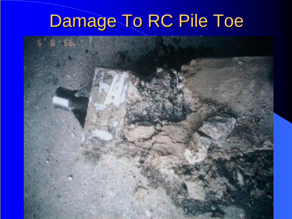
Damage To RC Pile ToeDamage To RC Pile Toe
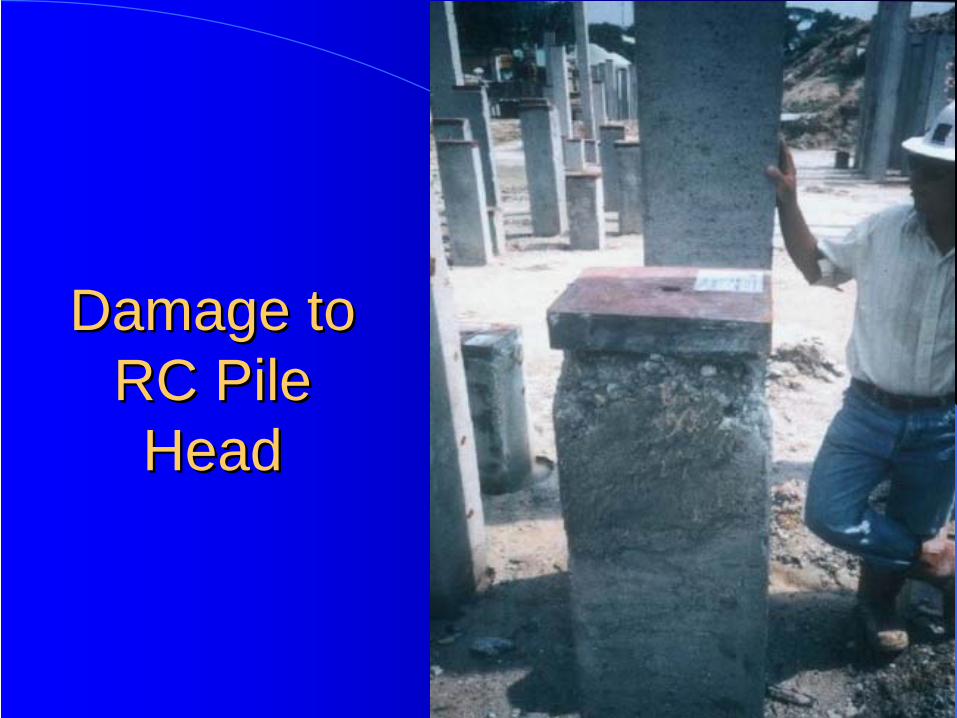
Damage to Damage to RC Pile RC Pile HeadHead
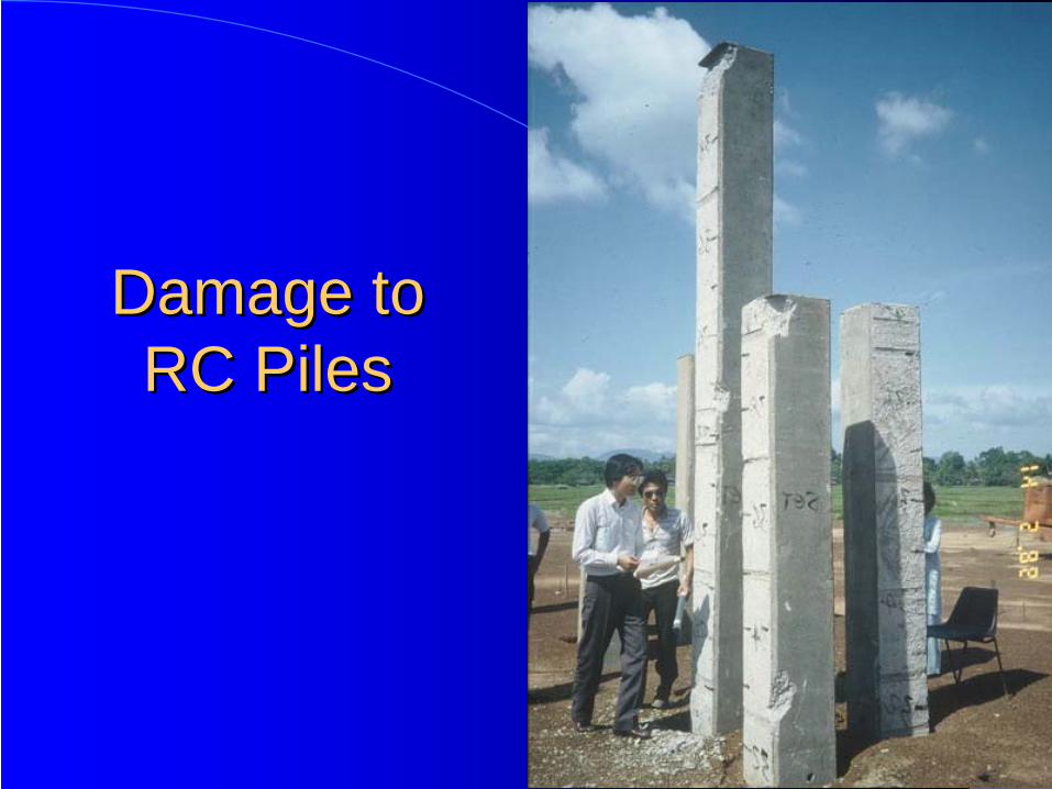
Damage to Damage to RC PilesRC Piles
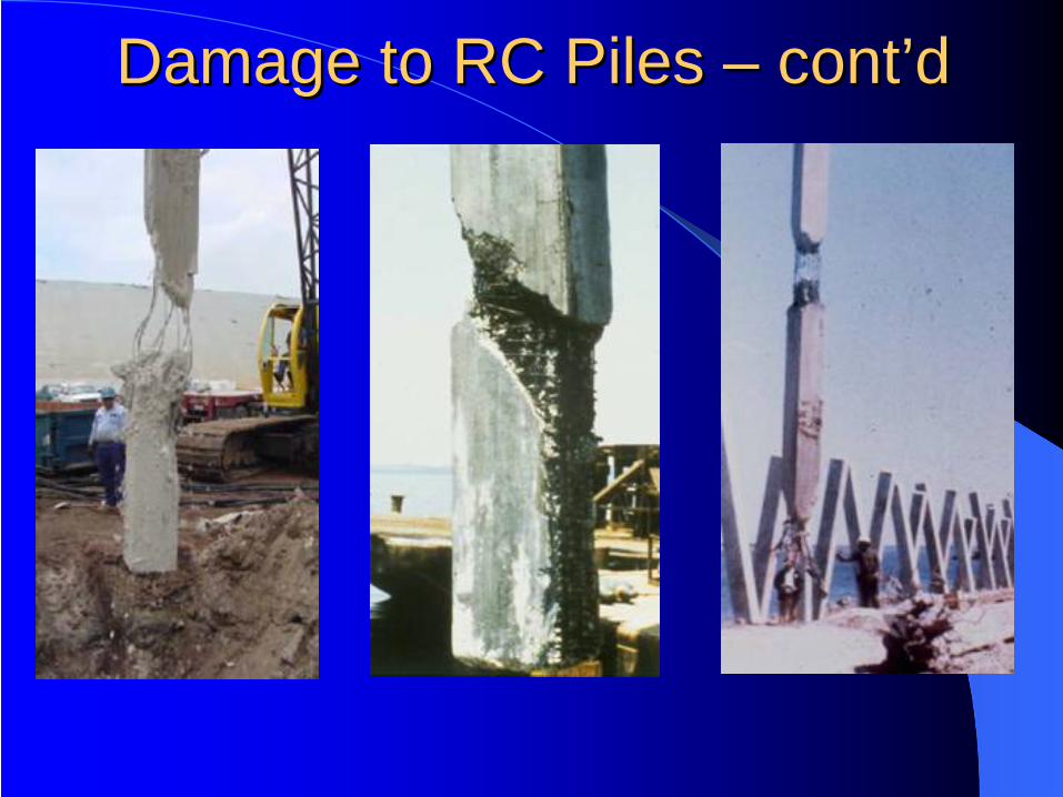
Damage to RC Piles Damage to RC Piles –– contcont’’d d
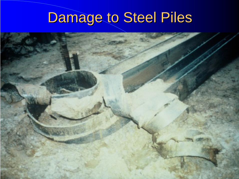
Damage to Steel PilesDamage to Steel Piles
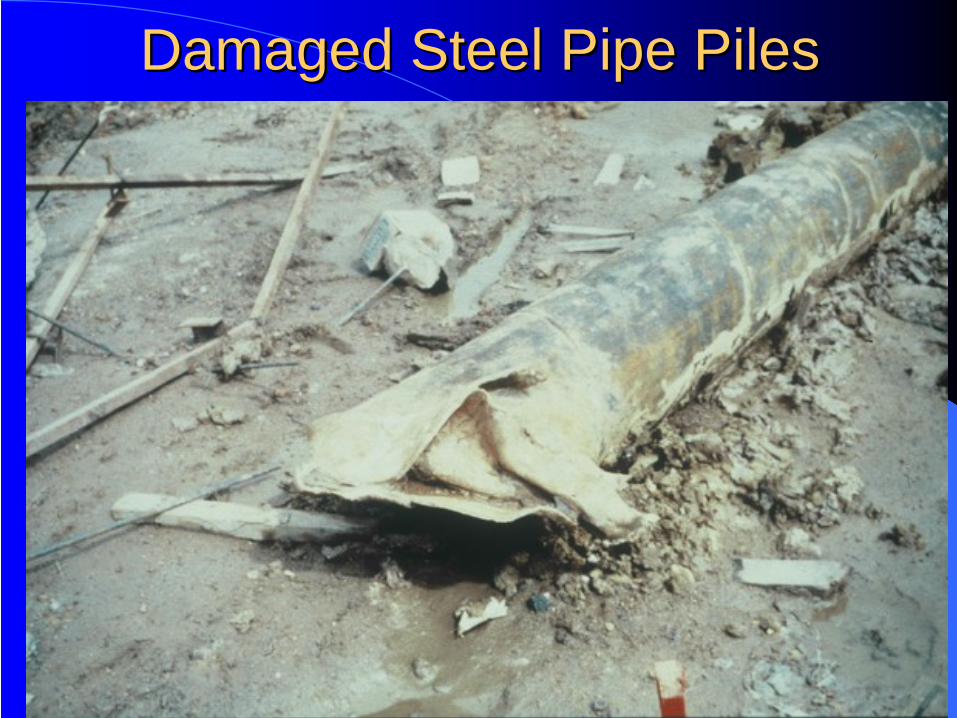
Damaged Steel Pipe PilesDamaged Steel Pipe Piles
Piling Problems

Piling Problems – Soft Ground
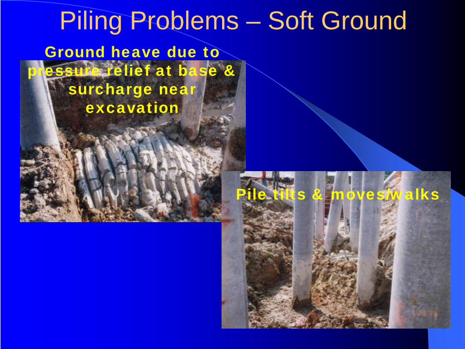
Ground heave due to pressure relief at base &
surcharge near excavation
Pile tilts & moves/walks
Piling Problems – Soft Ground
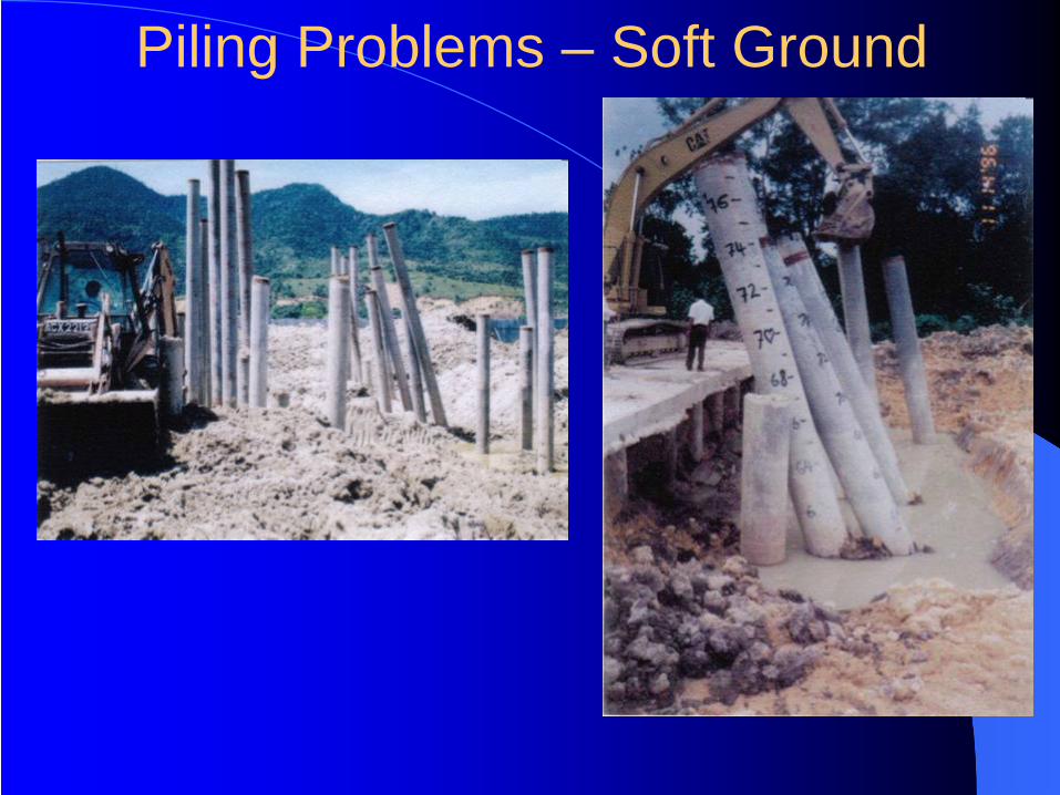
Piling Problems – Soft Ground
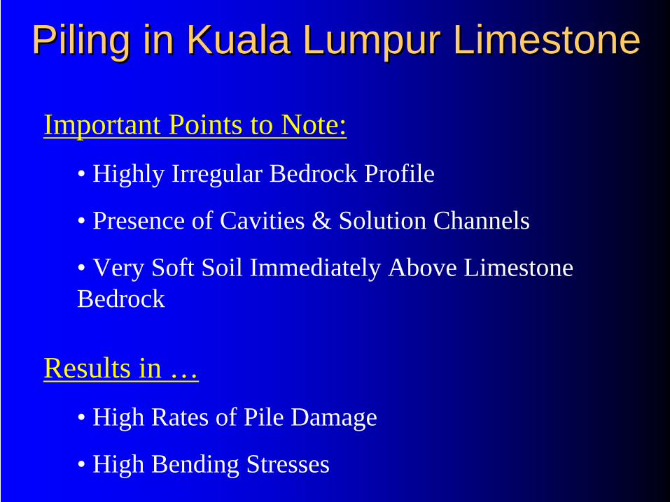
Piling in Kuala Lumpur LimestonePiling in Kuala Lumpur Limestone
Important Points to Note:• Highly Irregular Bedrock Profile
• Presence of Cavities & Solution Channels
• Very Soft Soil Immediately Above Limestone Bedrock
Results in …• High Rates of Pile Damage
• High Bending Stresses
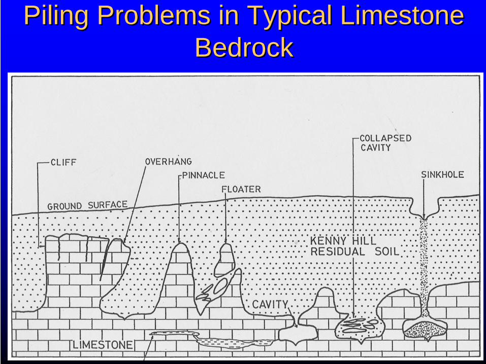
Piling Problems in Typical Limestone Piling Problems in Typical Limestone BedrockBedrock
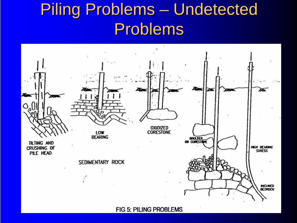
Piling Problems Piling Problems –– Undetected Undetected ProblemsProblems
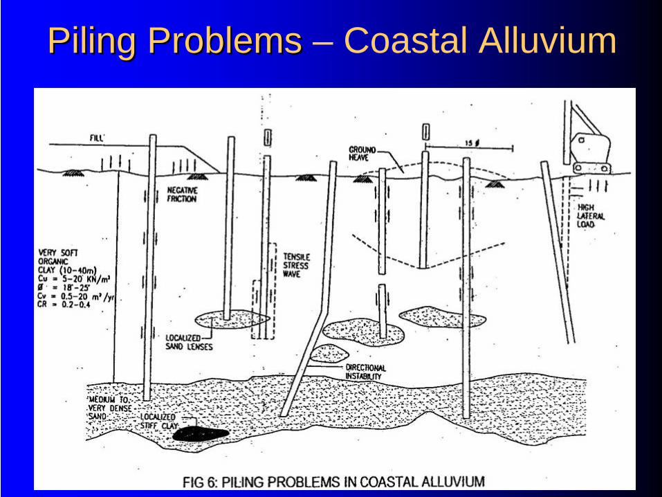
Piling Problems Piling Problems – Coastal Alluvium
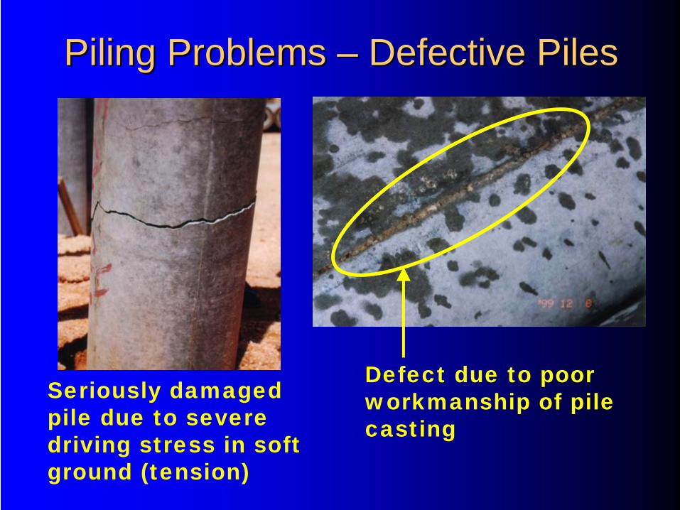
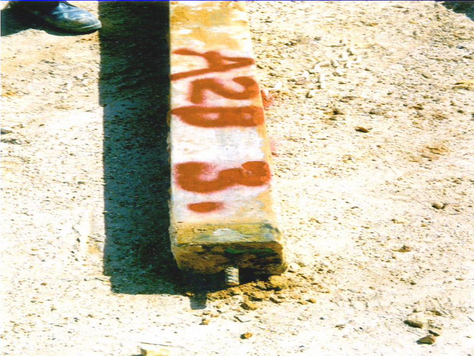
Piling Problems Piling Problems –– Defective PilesDefective Piles
Seriously damaged pile due to severe driving stress in soft ground (tension)
Defect due to poor workmanship of pile casting
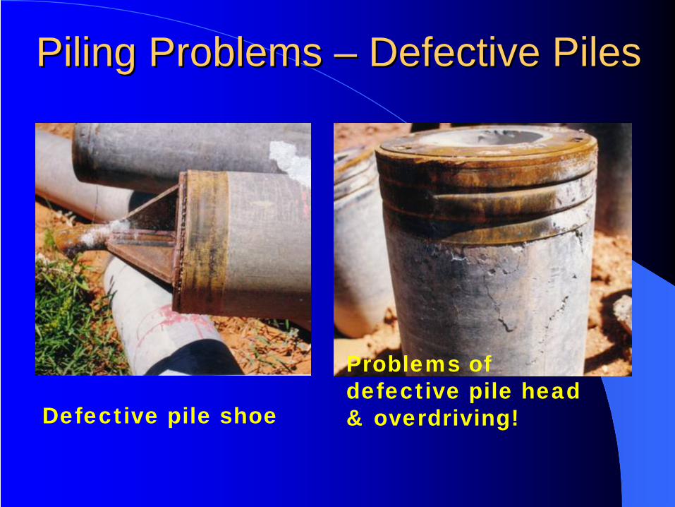
Defective pile shoe
Problems of defective pile head & overdriving!
Piling Problems Piling Problems –– Defective PilesDefective Piles
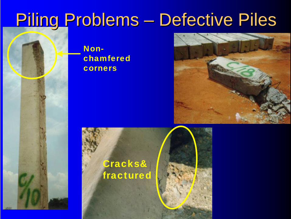
Cracks& fractured
Non- chamfered corners
Piling Problems Piling Problems –– Defective PilesDefective Piles
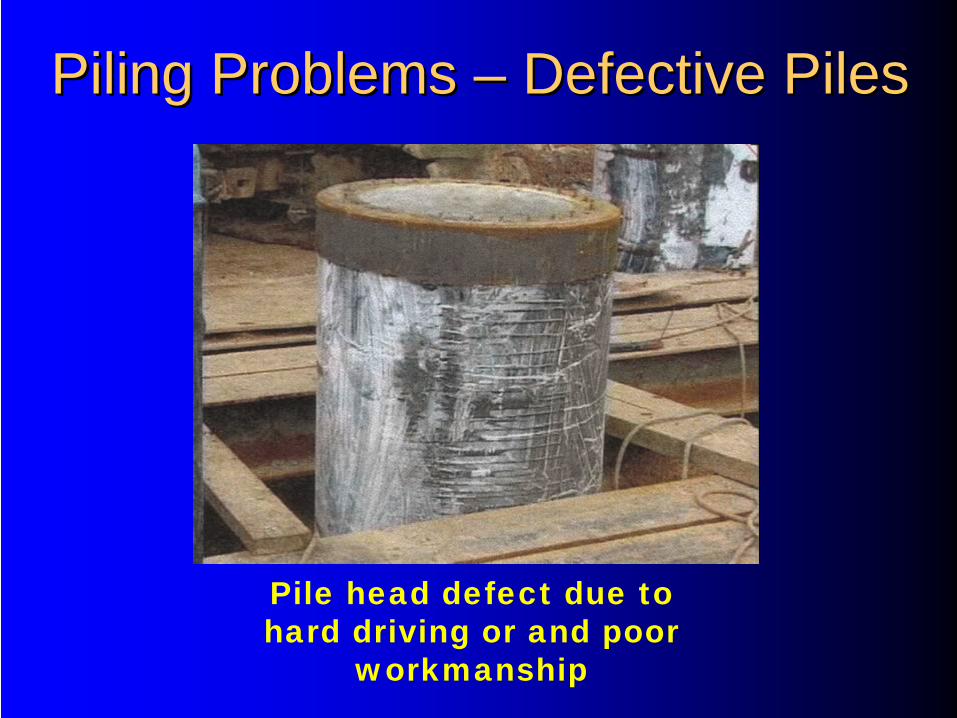
Pile head defect due to hard driving or and poor
workmanship
Piling Problems Piling Problems –– Defective PilesDefective Piles
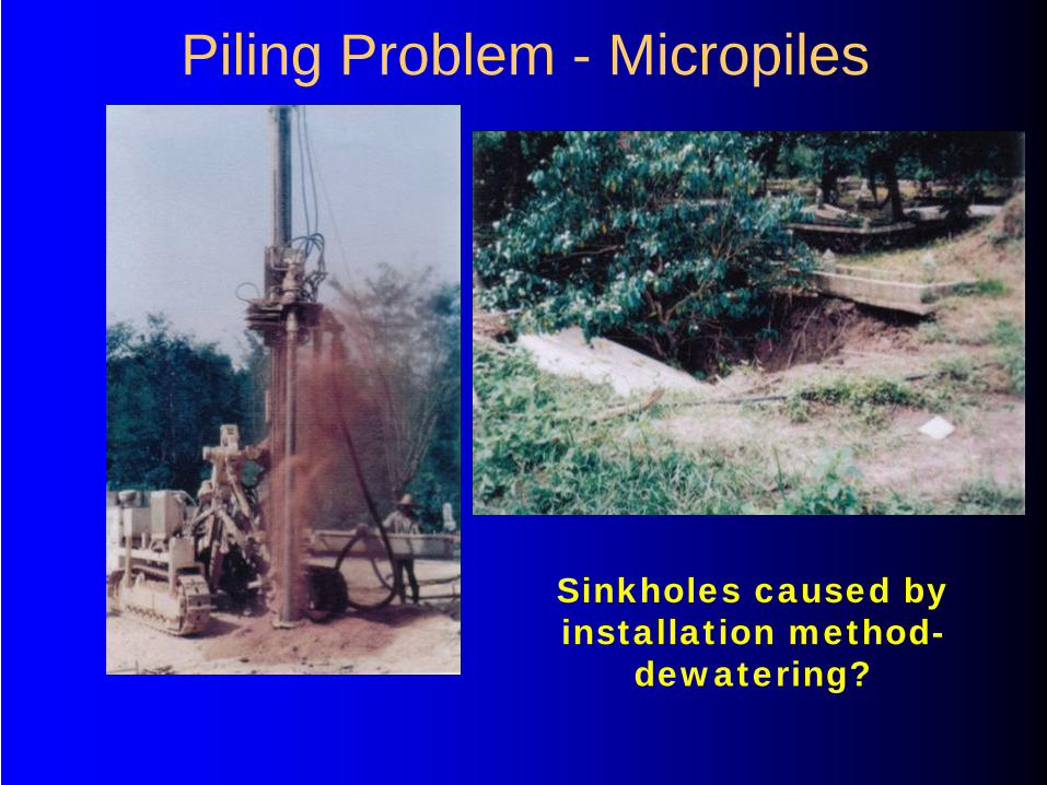
Piling Problem - Micropiles
Sinkholes caused by installation method-
dewatering?
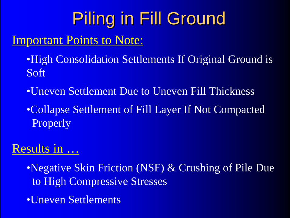
Piling in Fill GroundPiling in Fill GroundImportant Points to Note:
•High Consolidation Settlements If Original Ground is Soft•Uneven Settlement Due to Uneven Fill Thickness•Collapse Settlement of Fill Layer If Not Compacted
Properly
Results in …•Negative Skin Friction (NSF) & Crushing of Pile Due
to High Compressive Stresses•Uneven Settlements
Typical Design and Typical Design and Construction Issues #1Construction Issues #1
Pile Toe Slippage Due to Steep Incline Bedrock
Use Oslo Point Shoe To Minimize Pile Damage
Issue #1
Solution #1
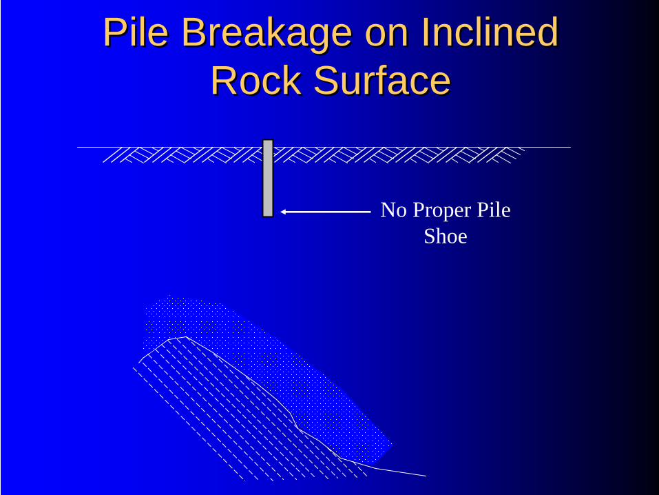
Pile Breakage on Inclined Pile Breakage on Inclined Rock SurfaceRock Surface
No Proper Pile Shoe
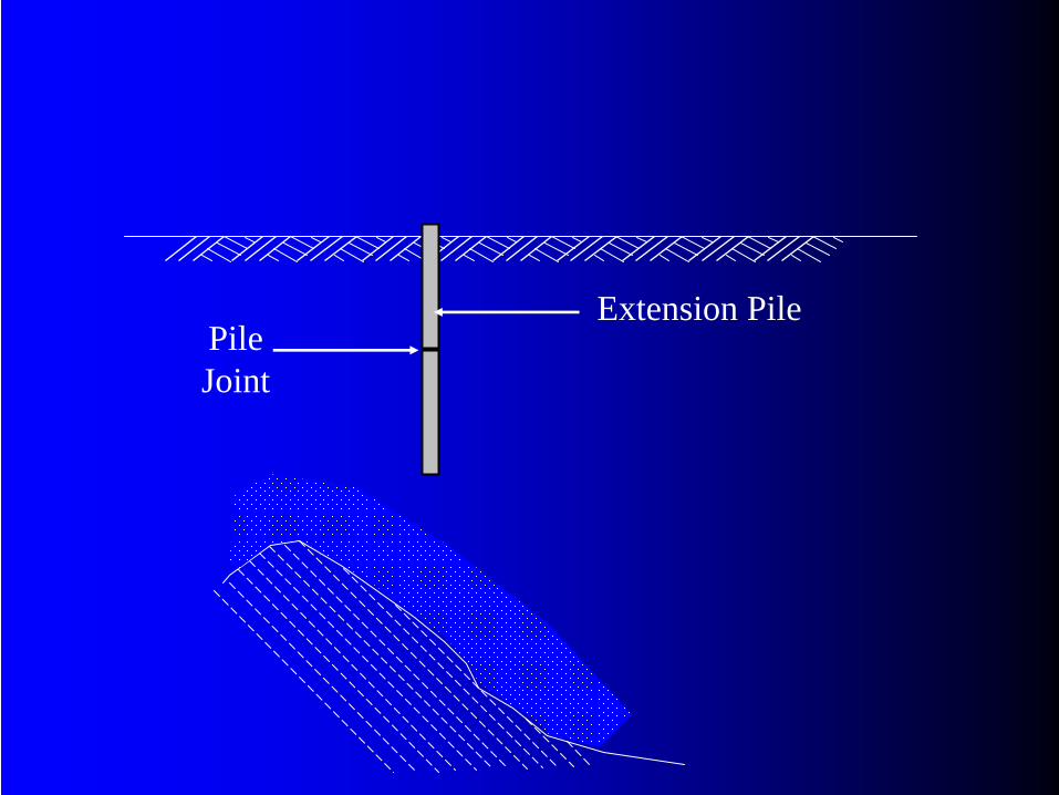
Extension PilePileJoint
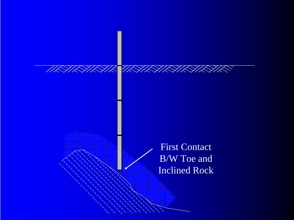
First Contact B/W Toe and Inclined Rock
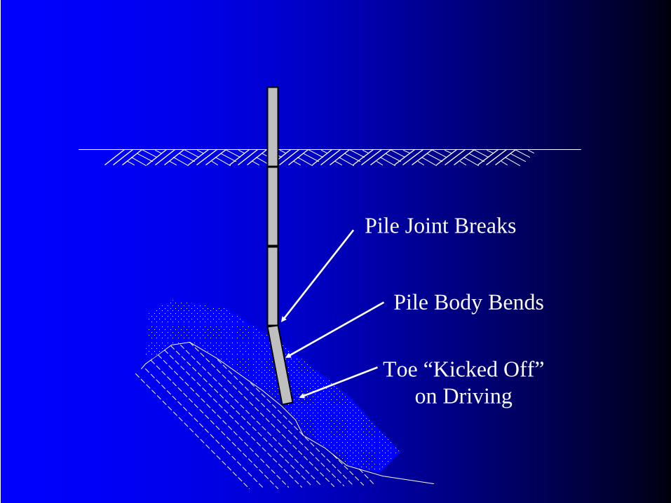
Toe “Kicked Off” on Driving
Pile Body Bends
Pile Joint Breaks
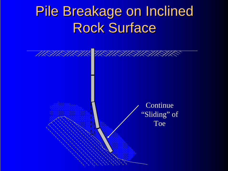
Pile Breakage on Inclined Pile Breakage on Inclined Rock SurfaceRock Surface
Continue “Sliding” of
Toe
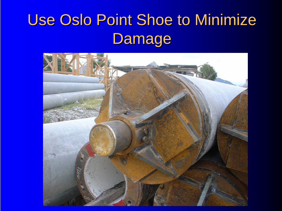
Use Oslo Point Shoe to Minimize Use Oslo Point Shoe to Minimize DamageDamage
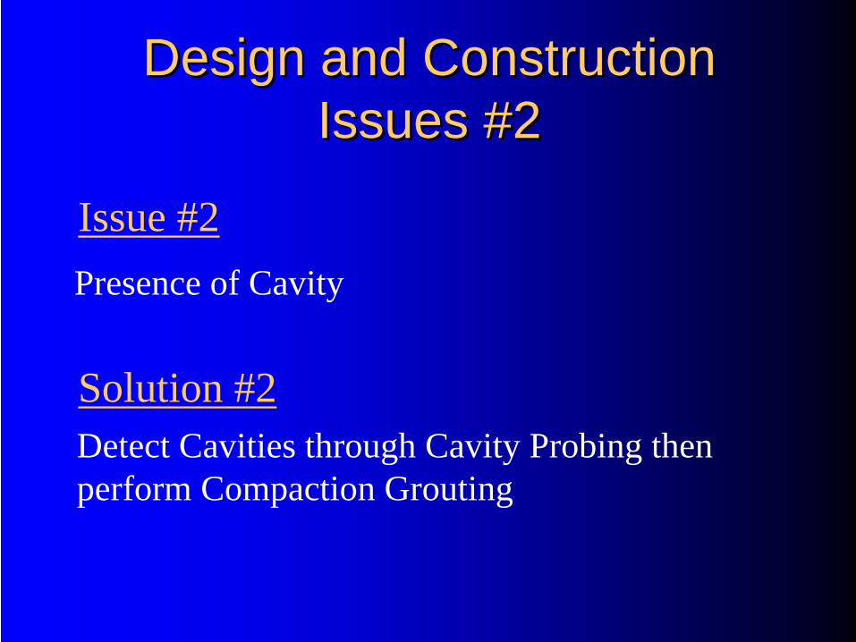
Design and Construction Design and Construction Issues #2Issues #2
Presence of Cavity
Detect Cavities through Cavity Probing then perform Compaction Grouting
Issue #2
Solution #2

Presence of CavityPresence of Cavity
Pile Sitting on Limestone with Cavity
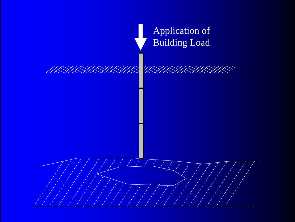
Application of Building Load
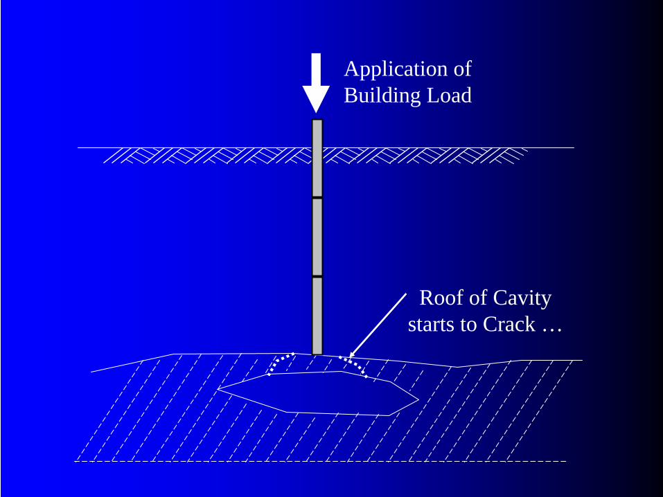
Application of Building Load
Roof of Cavity starts to Crack …
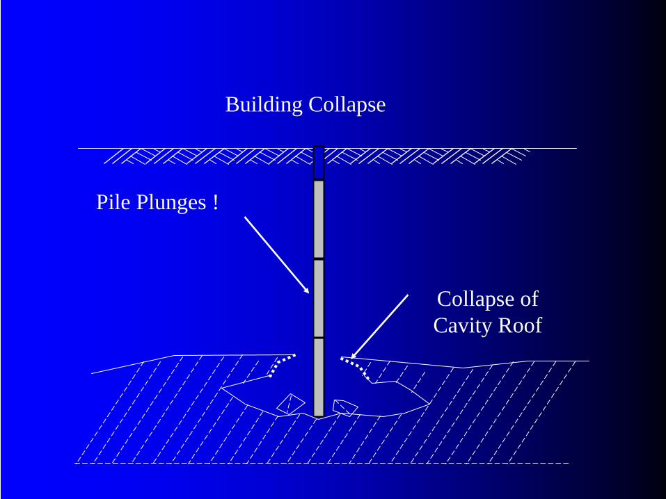
Collapse of Cavity Roof
Pile Plunges !
Building Collapse
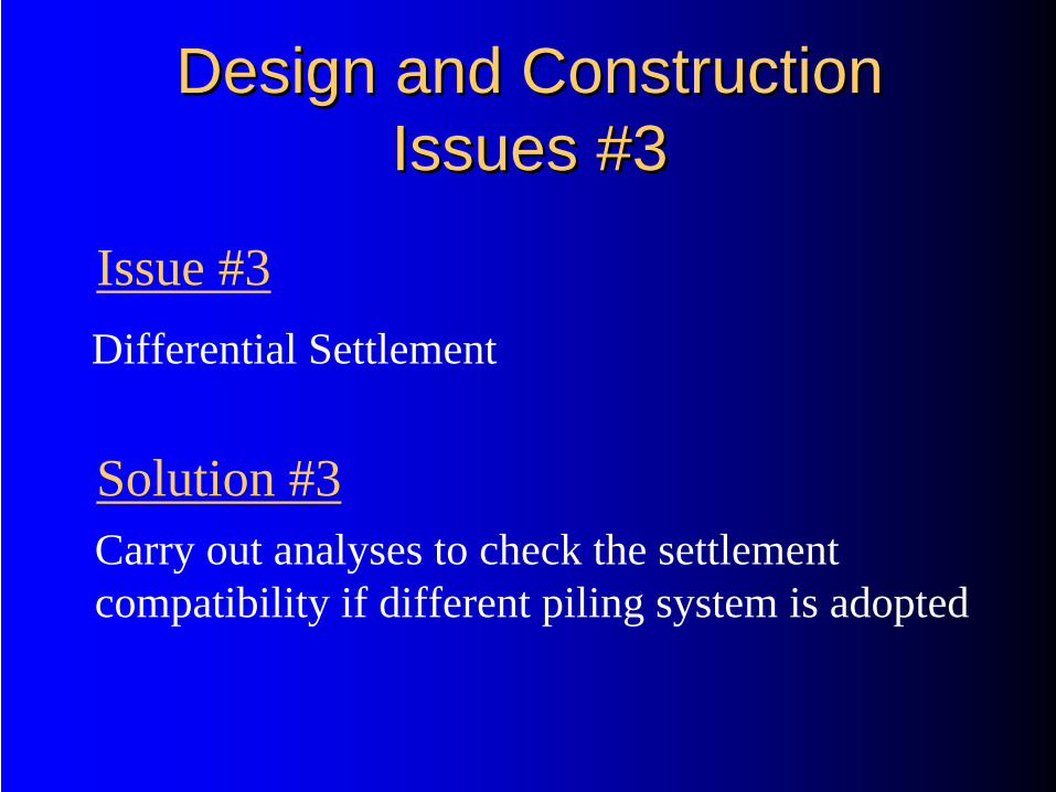
Design and Construction Design and Construction Issues #3Issues #3
Differential Settlement
Carry out analyses to check the settlement compatibility if different piling system is adopted
Issue #3
Solution #3
Piling in Progress
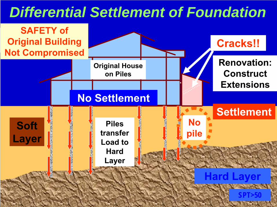
Differential Settlement of Foundation
Original House on Piles
Hard LayerSPT>50
Cracks!!
No pile
SettlementSoft
Layer
Link House Construction
Renovation: Construct
Extensions
Piles transfer Load to
Hard Layer
No Settlement
SAFETY of Original Building
Not Compromised
Piling in Progress
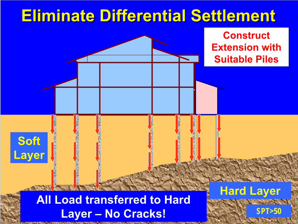
Eliminate Differential SettlementEliminate Differential Settlement
Hard LayerSPT>50
Soft Layer
Construct Extension with Suitable Piles
All Load transferred to Hard Layer –
No Cracks!
Piling in Progress
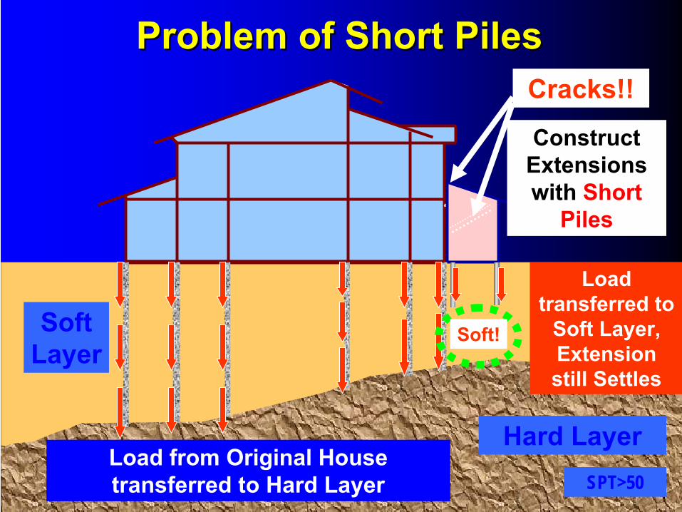
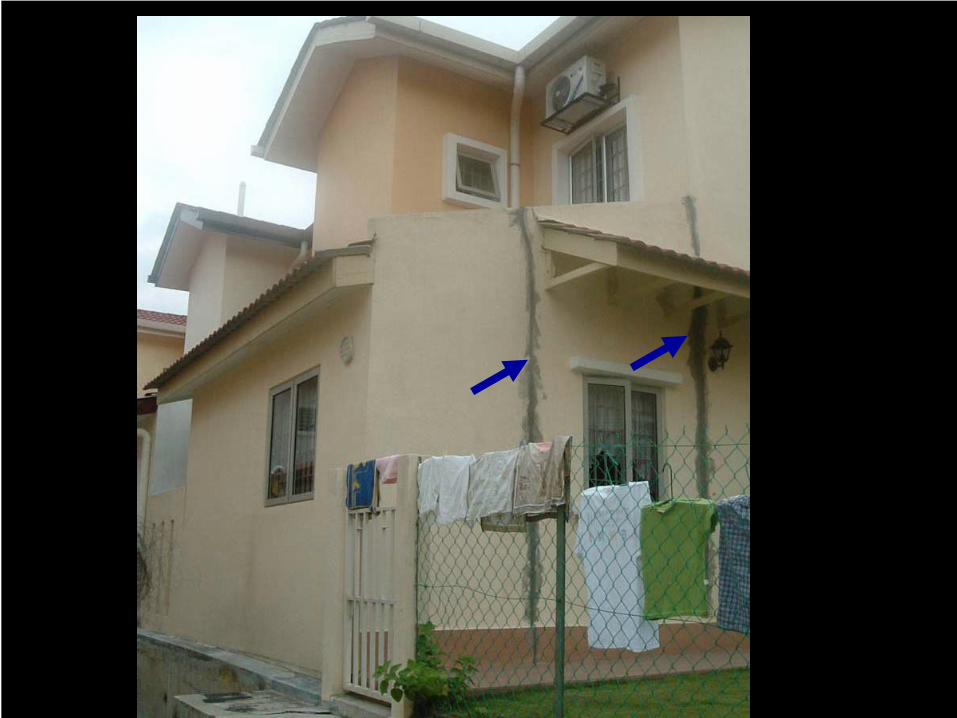
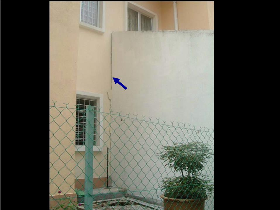
Problem of Short PilesProblem of Short Piles
Hard LayerSPT>50
Soft Layer
Load from Original House transferred to Hard Layer
Cracks!!
Soft!
Load transferred to
Soft Layer, Extension still Settles
Construct Extensions with
Short
Piles
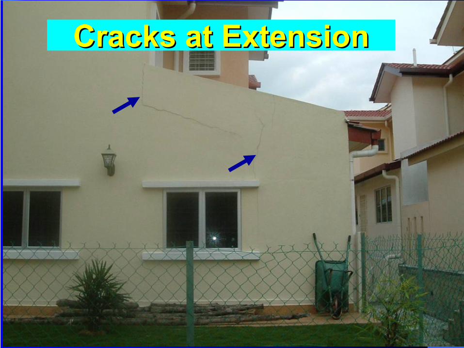
Cracks at ExtensionCracks at Extension

Typical Design and Typical Design and Construction Issues #4Construction Issues #4
Costly conventional piling design – piled to set to deep layer in soft ground
-Strip footings / Raft
-Floating Piles
Issue #4
Solution #4
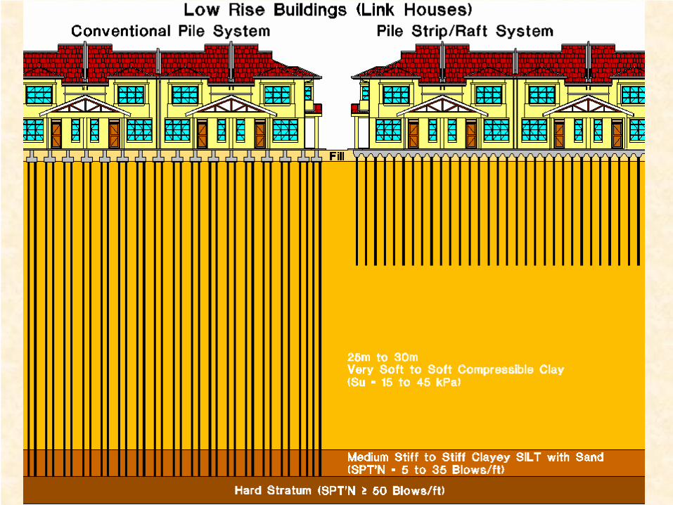
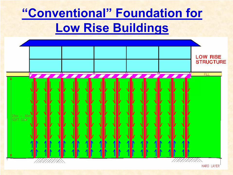
“Conventional”
Foundation for Low Rise Buildings
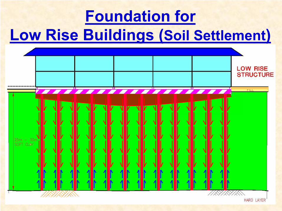
Foundation for Low Rise Buildings (Soil Settlement)
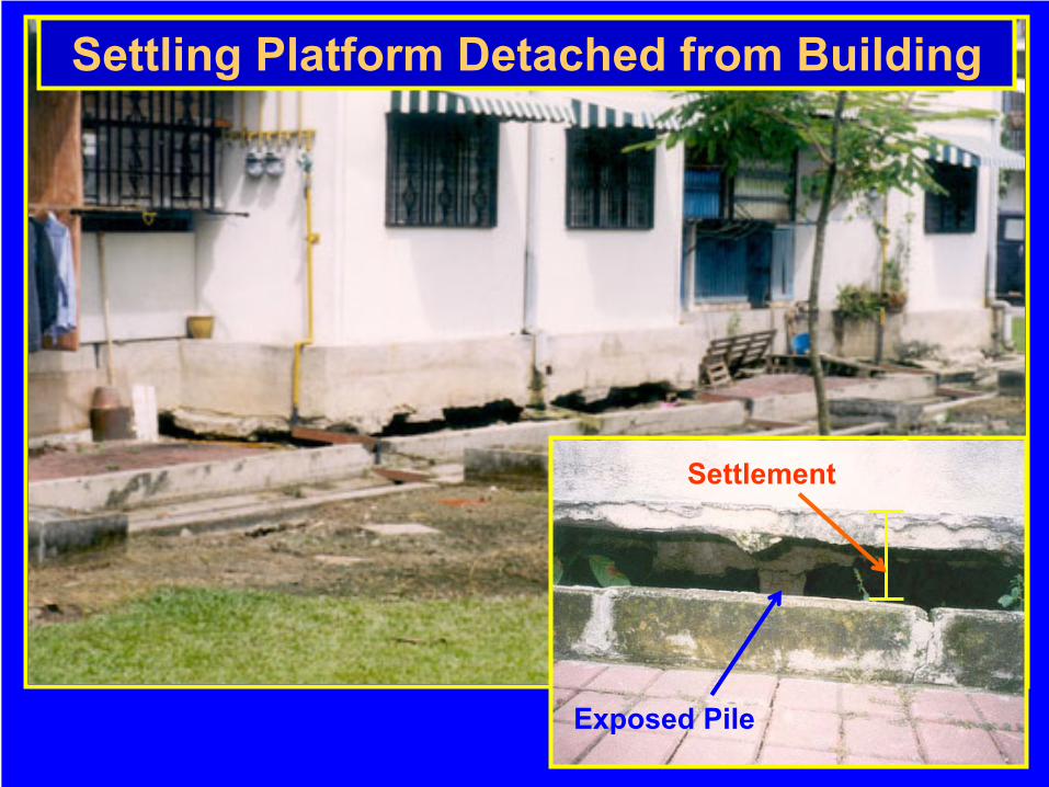
Exposed Pile
Settlement
Settling Platform Detached from Building
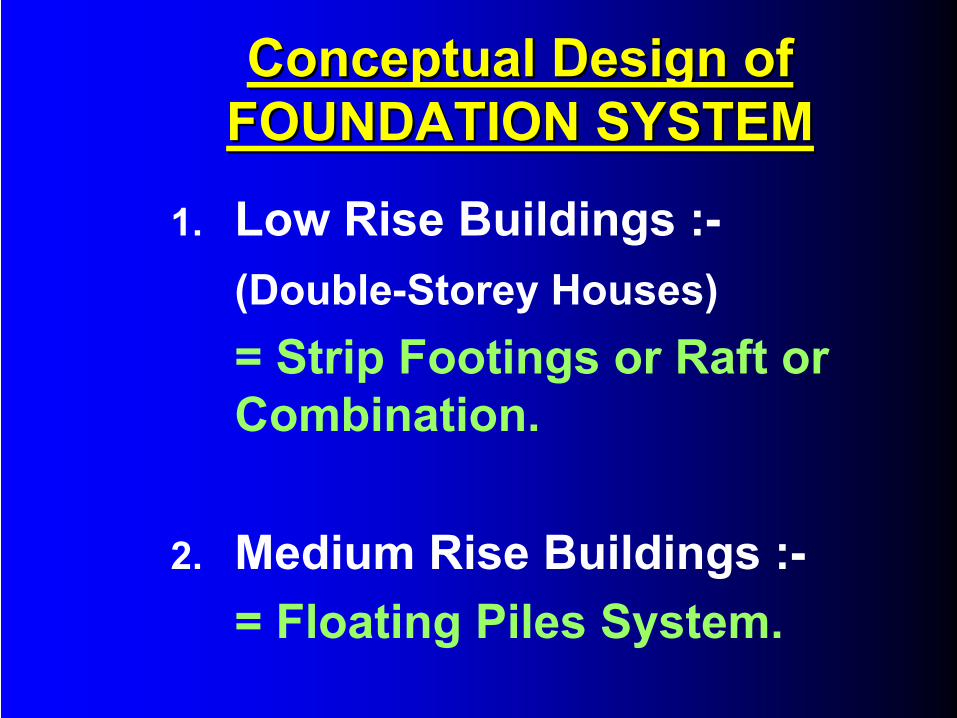
Conceptual Design of Conceptual Design of FOUNDATION SYSTEMFOUNDATION SYSTEM
1.
Low Rise Buildings :-(Double-Storey Houses)= Strip Footings or Raft or Combination.
2.
Medium Rise Buildings :-= Floating Piles System.
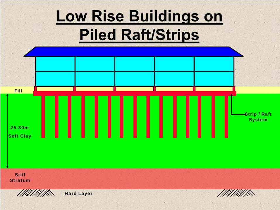
Low Rise Buildings on Piled Raft/Strips
Strip / Raft System
Stiff Stratum
Hard Layer
Fill
25-30m
Soft Clay
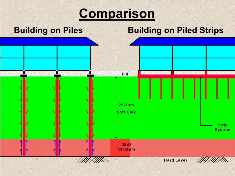
Comparison
Strip System
Stiff Stratum
Hard Layer
Fill
25-30m
Soft Clay
Building on Piles Building on Piled Strips
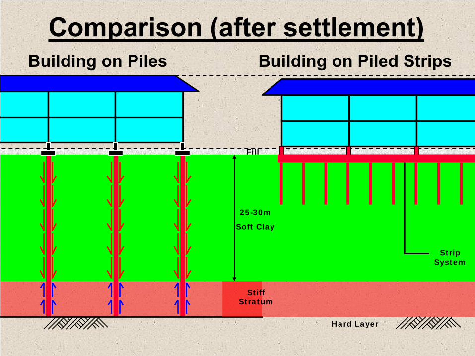
Comparison (after settlement)Building on Piles Building on Piled Strips
Strip System
Stiff Stratum
Hard Layer
Fill
25-30m
Soft Clay
Advantages of Advantages of Floating Piles SystemFloating Piles System
1. Cost Effective.
2. No Downdrag problems on the Piles.
3. Insignificant Differential Settlement between Buildings and Platform.
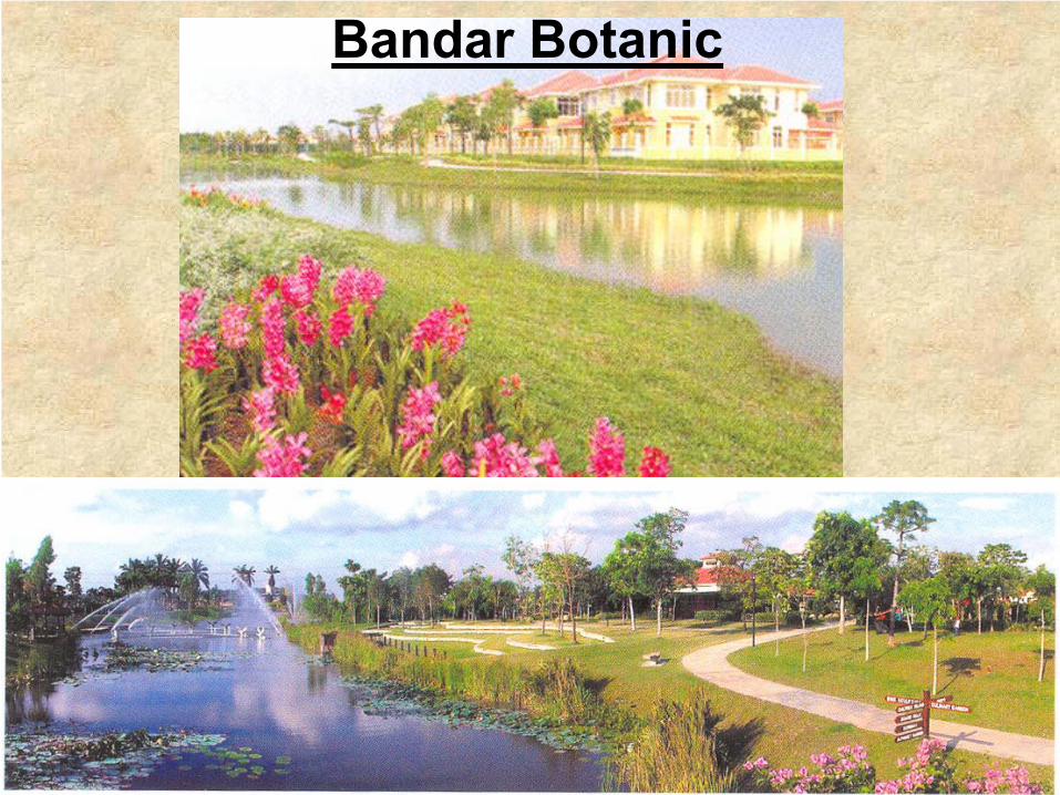
Bandar Botanic
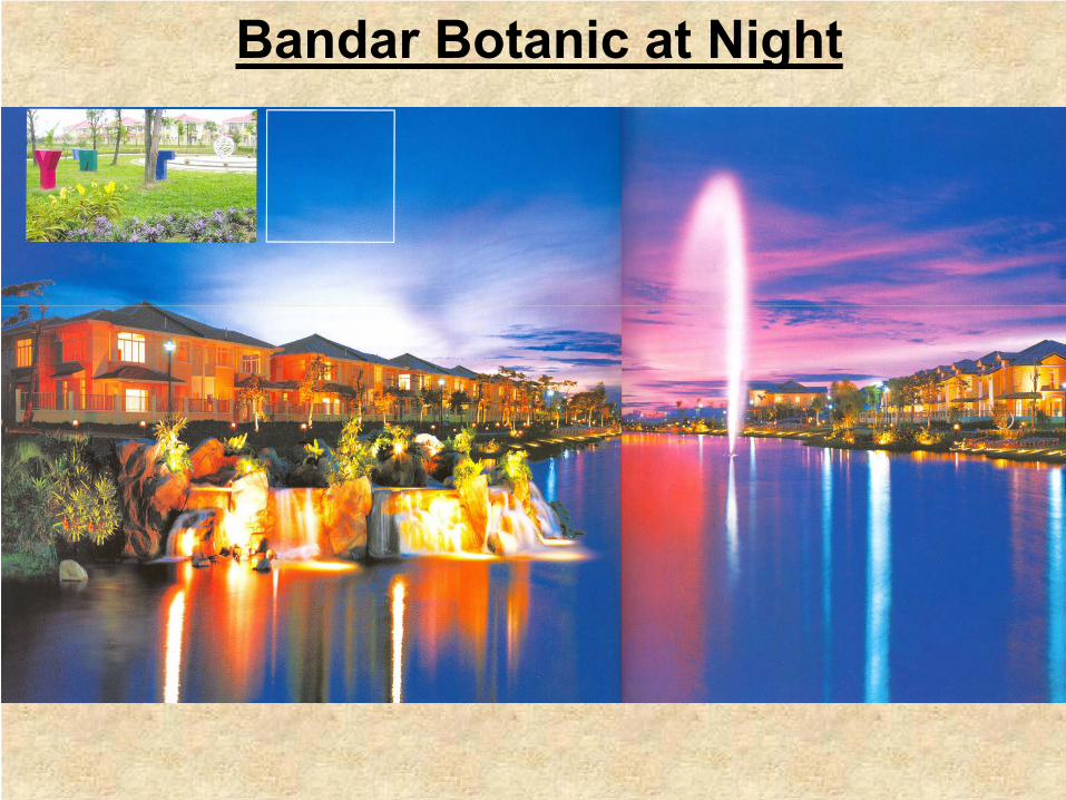
Bandar Botanic at Night

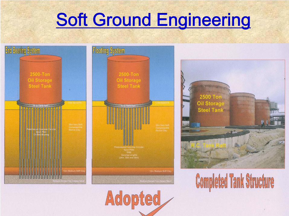
Soft Ground Engineering
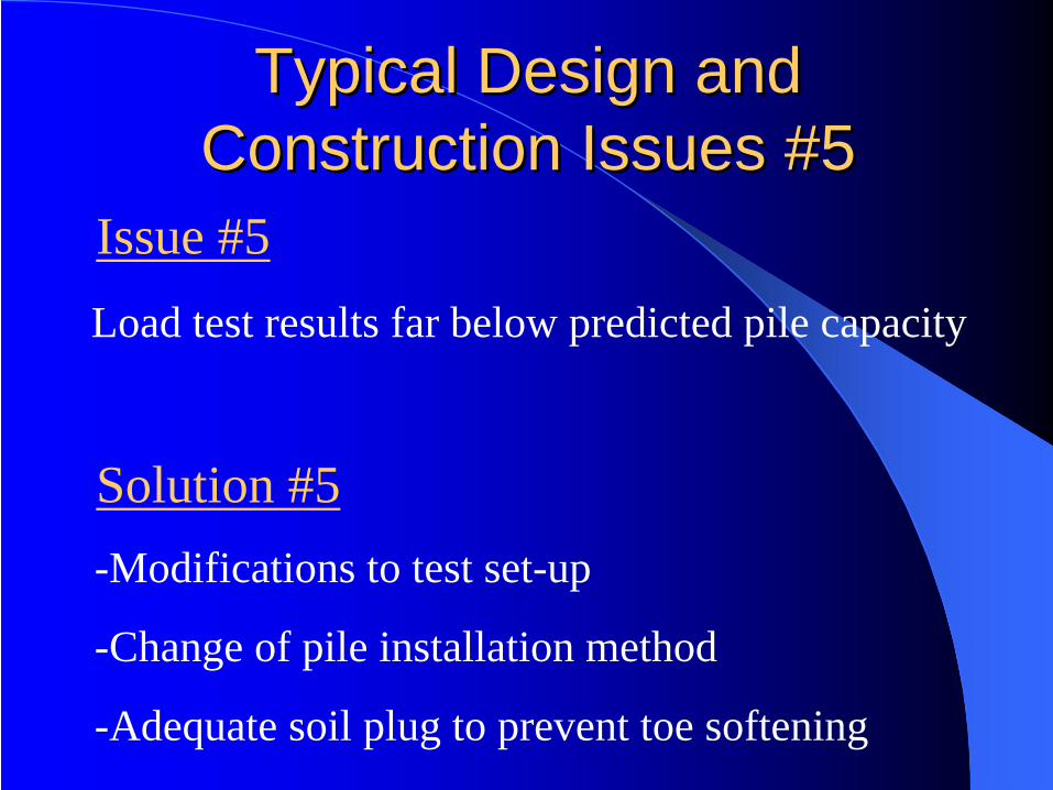
Typical Design and Typical Design and Construction Issues #5Construction Issues #5
Load test results far below predicted pile capacity
-Modifications to test set-up
-Change of pile installation method
-Adequate soil plug to prevent toe softening
Issue #5
Solution #5

Testing SetTesting Set--up Using Reaction up Using Reaction PilesPiles
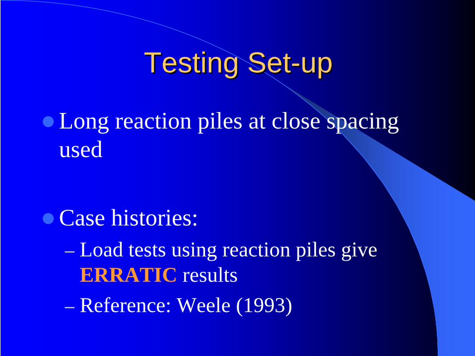
Testing SetTesting Set--up up
Long reaction piles at close spacing used
Case histories:– Load tests using reaction piles give
ERRATIC results– Reference: Weele (1993)
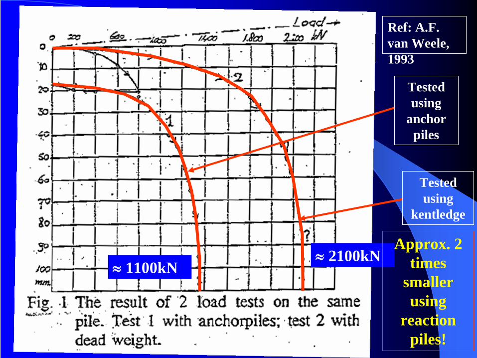
≈
1100kN
Tested using
anchor piles
≈
2100kN
Tested using
kentledge
Approx. 2 times
smaller using
reaction piles!
Ref: A.F. van Weele, 1993
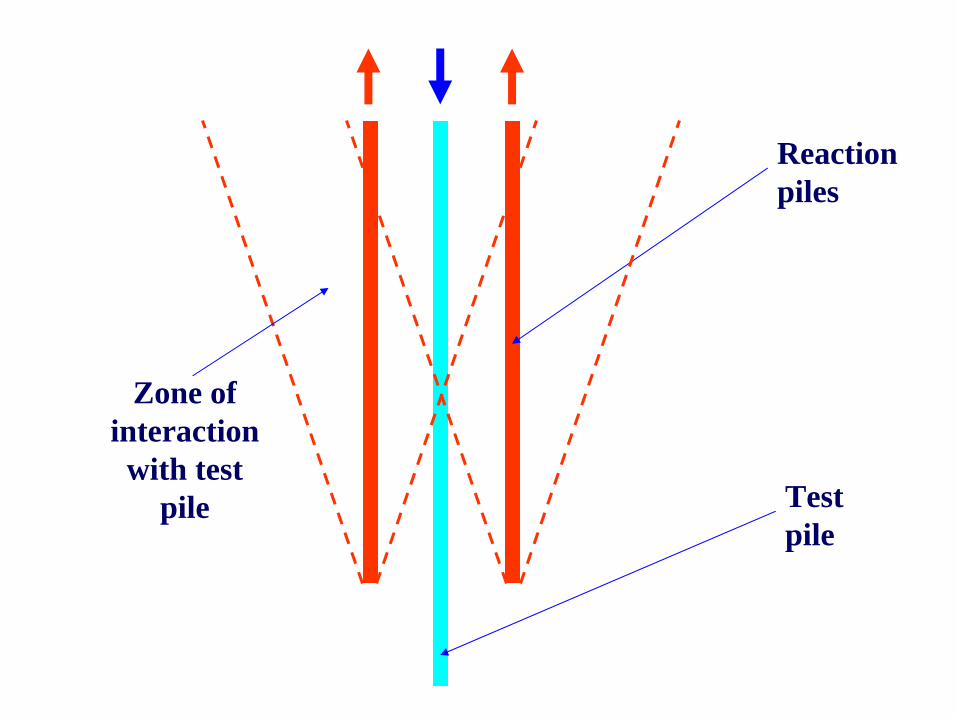
Reaction piles
Test pile
Zone of interaction
with test pile
Testing SetTesting Set--up up
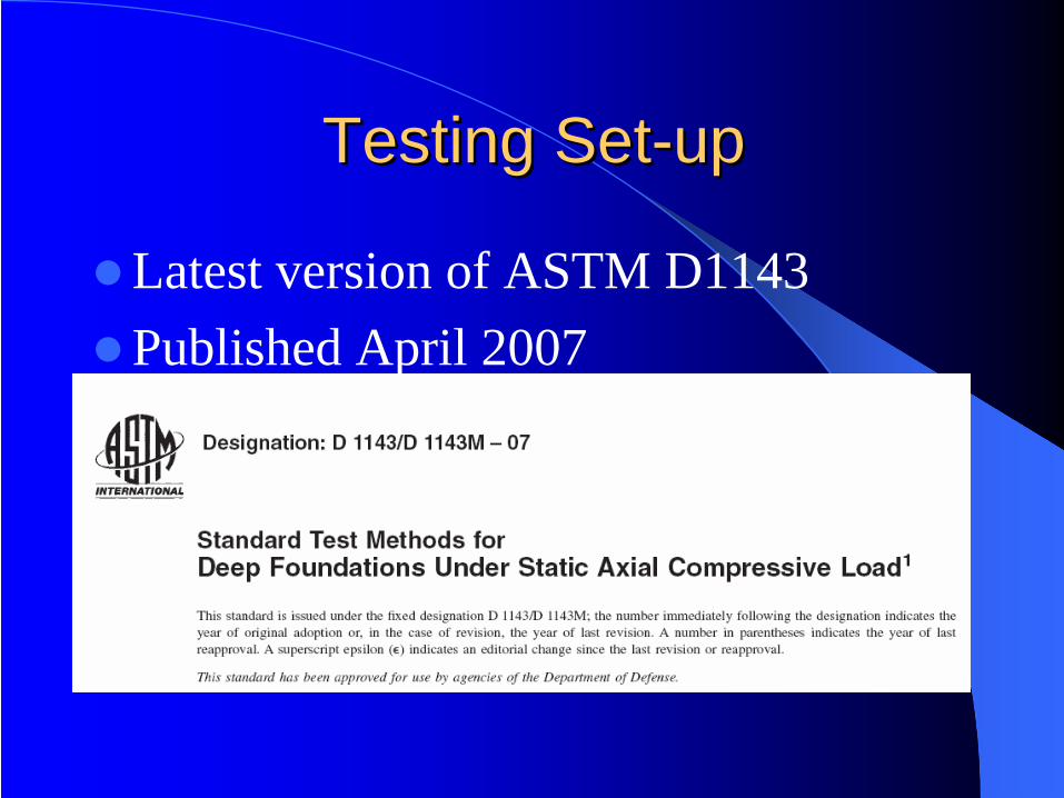
Latest version of ASTM D1143Published April 2007
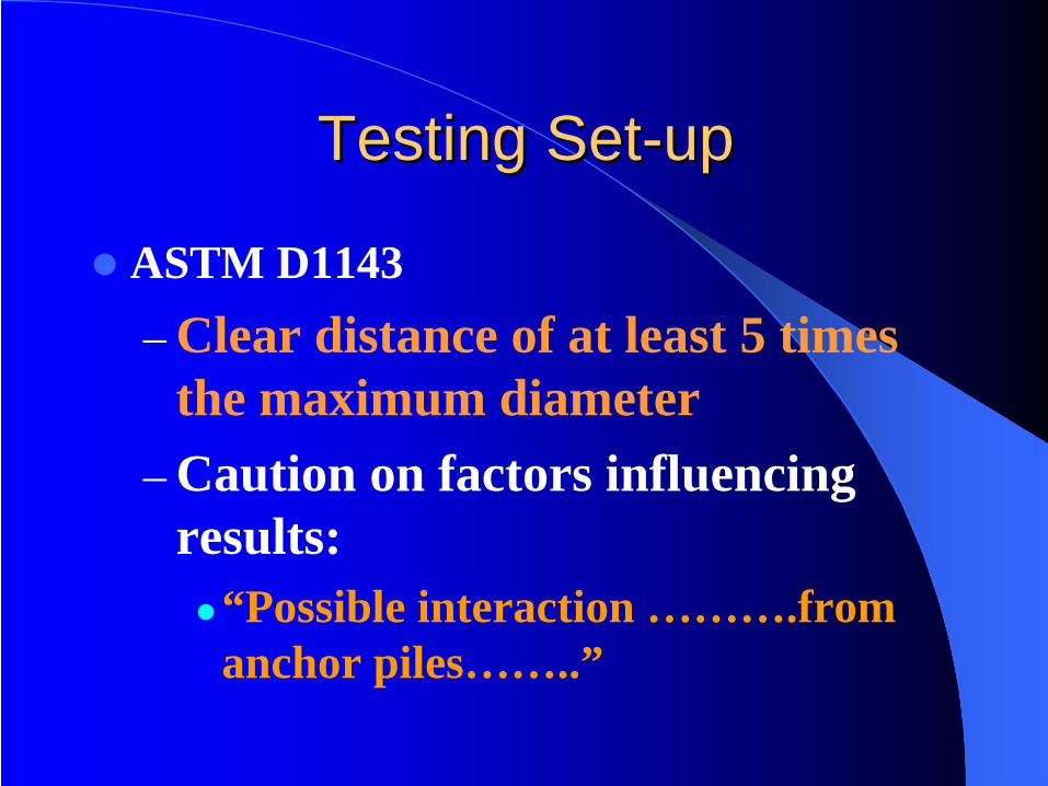
Testing SetTesting Set--upup
ASTM D1143– Clear distance of at least 5 times
the maximum diameter– Caution on factors influencing
results:“Possible interaction ……….from anchor piles……..”

Drilling to the Casing Tip Drilling to the Casing Tip to Form to Form ““Bored PileBored Pile””
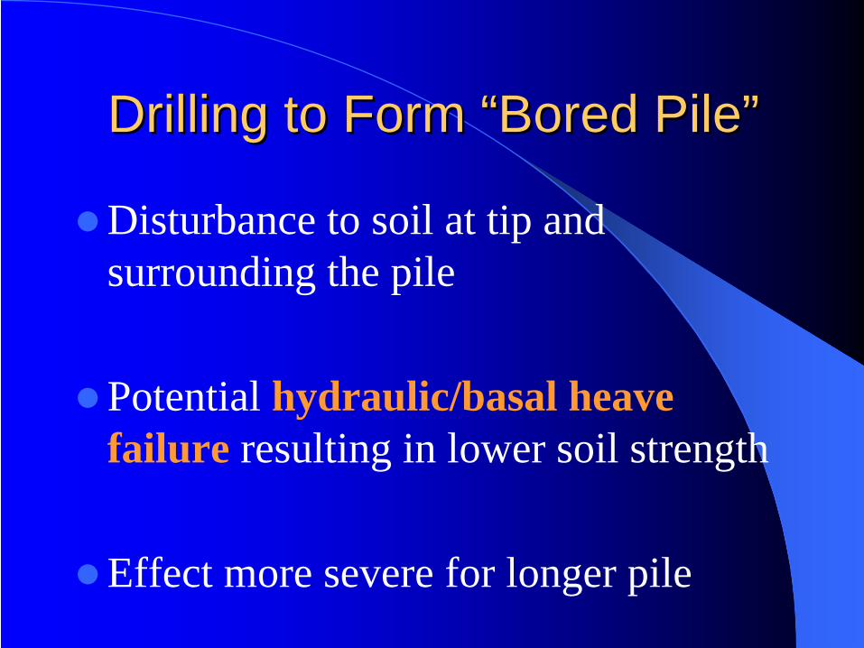
Drilling to Form Drilling to Form ““Bored PileBored Pile””
Disturbance to soil at tip and surrounding the pile
Potential hydraulic/basal heave failure resulting in lower soil strength
Effect more severe for longer pile

Construction of Construction of ““Bored PileBored Pile””1. Install Permanent Steel
Casing to Pile Toe
2. Removal of Soil within Steel Casing to Toe of Casing
3. Installation of Reinforcement and Concreting
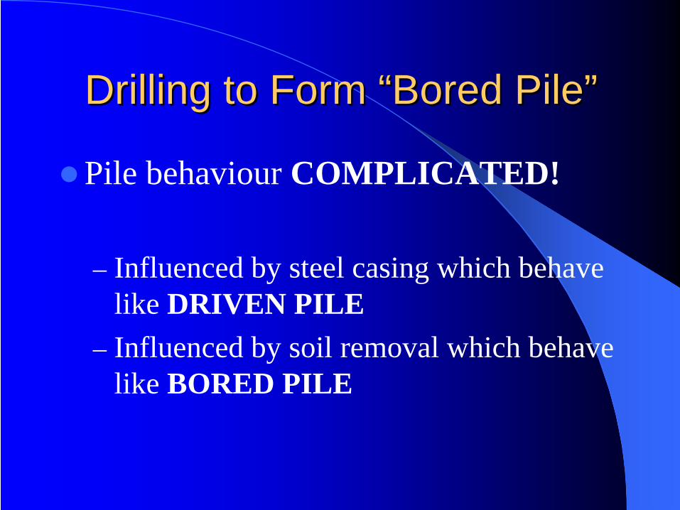
Drilling to Form Drilling to Form ““Bored PileBored Pile””
Pile behaviour COMPLICATED!
– Influenced by steel casing which behave like DRIVEN PILE
– Influenced by soil removal which behave like BORED PILE
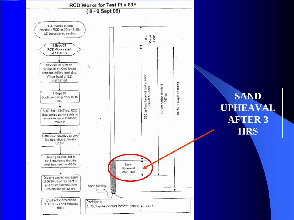
SAND UPHEAVAL
AFTER 3 HRS
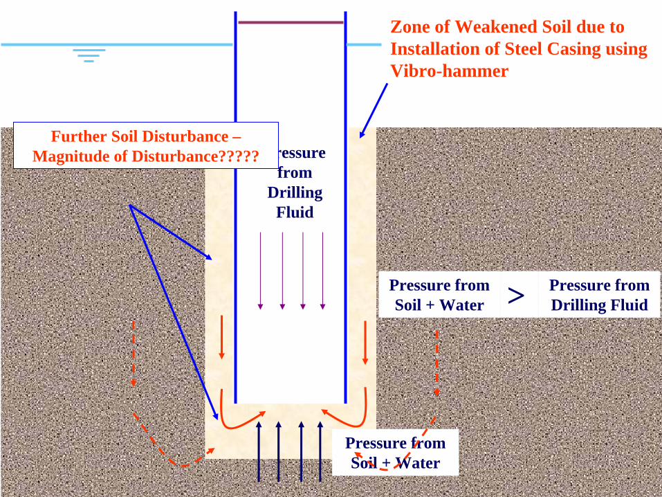
Zone of Weakened Soil due to Installation of Steel Casing using Vibro-hammer
Pressure from
Drilling Fluid
Pressure from Soil + Water
Pressure from Soil + Water > Pressure from
Drilling Fluid
Further Soil Disturbance – Magnitude of Disturbance?????
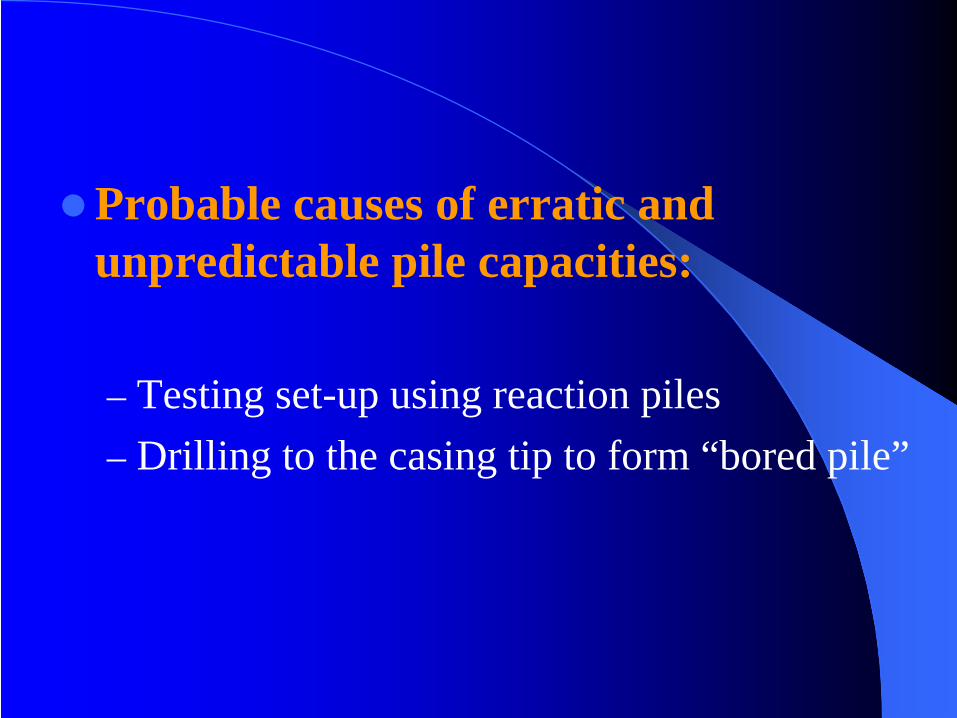
Probable causes of erratic and unpredictable pile capacities:
– Testing set-up using reaction piles– Drilling to the casing tip to form “bored pile”
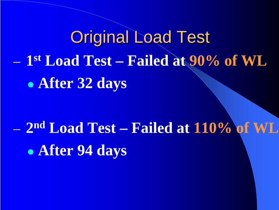
Original Load TestOriginal Load Test– 1st Load Test – Failed at 90% of WL
After 32 days
– 2nd Load Test – Failed at 110% of WLAfter 94 days
Recommendations:
– Open-ended spun pile or steel pipe pile with adequate soil plug
– Use of impact hammer instead of vibro- hammer
– Trial piles for correlation between static load test and high strain dynamic load test
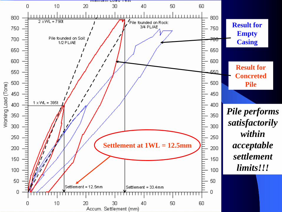
Result for Concreted
Pile
Result for Empty Casing
Pile performs satisfactorily
within acceptable settlement limits!!!
Settlement at 1WL = 12.5mm

Load Test Results at P52WLoad Test Results at P52W– Result for Empty Casing
1xWL: pile settlement= 20mm(residual settlement= 1mm)1.9xWL: pile settlement= 50mm(residual settlement= 3mm)
– Result for Cast Pile1xWL: pile settlement= 12.5mm(residual settlement= 1mm)2xWL: pile settlement= 33.4mm(residual settlement= 7mm)
The Pile is Stiffer after
Concreting !!
Larger Residual Settlement due to Disturbance from
RCD work !!
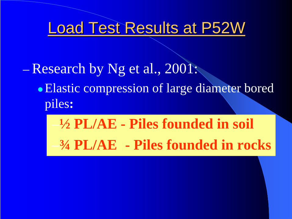
Load Test Results at P52WLoad Test Results at P52W
– Research by Ng et al., 2001:Elastic compression of large diameter bored piles:–½ PL/AE - Piles founded in soil–¾ PL/AE - Piles founded in rocks
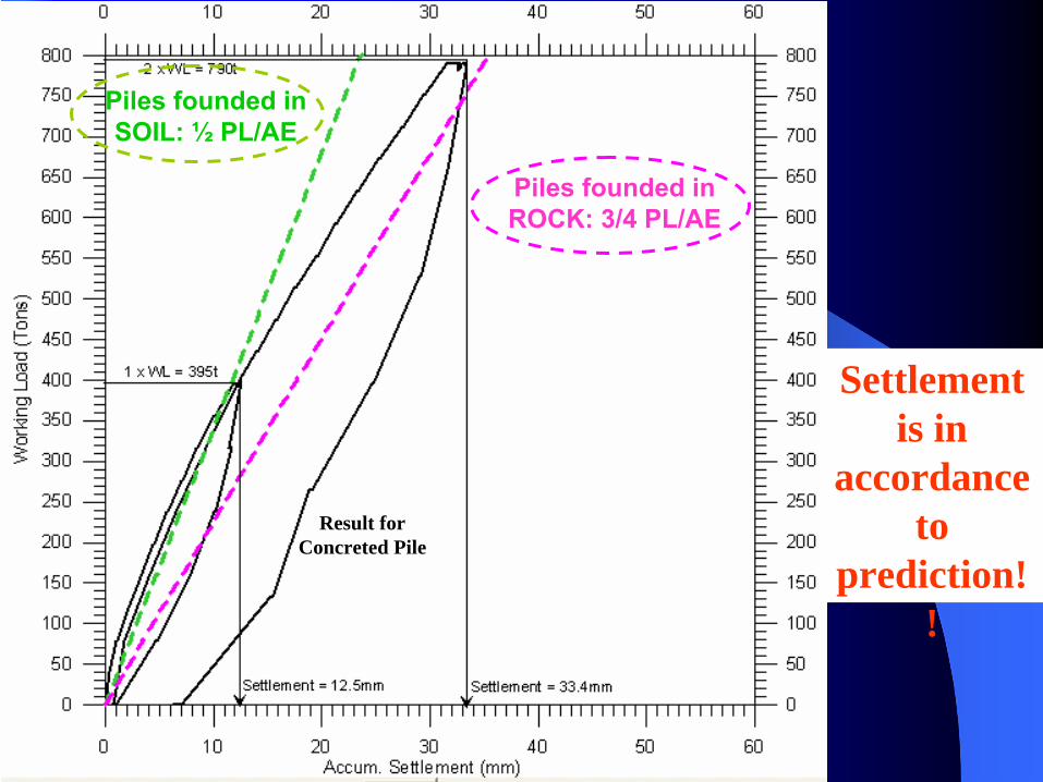
Result for Concreted Pile
Piles founded in SOIL: ½
PL/AE
Piles founded in ROCK: 3/4 PL/AE
Settlement is in
accordance to
prediction! !
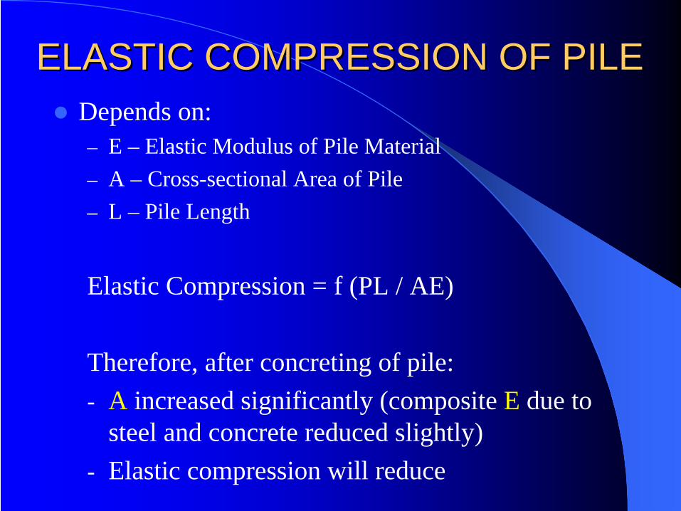
Depends on:– E – Elastic Modulus of Pile Material– A – Cross-sectional Area of Pile– L – Pile Length
Elastic Compression = f (PL / AE)
Therefore, after concreting of pile:- A increased significantly (composite E due to
steel and concrete reduced slightly)- Elastic compression will reduce
ELASTIC COMPRESSION OF PILEELASTIC COMPRESSION OF PILE
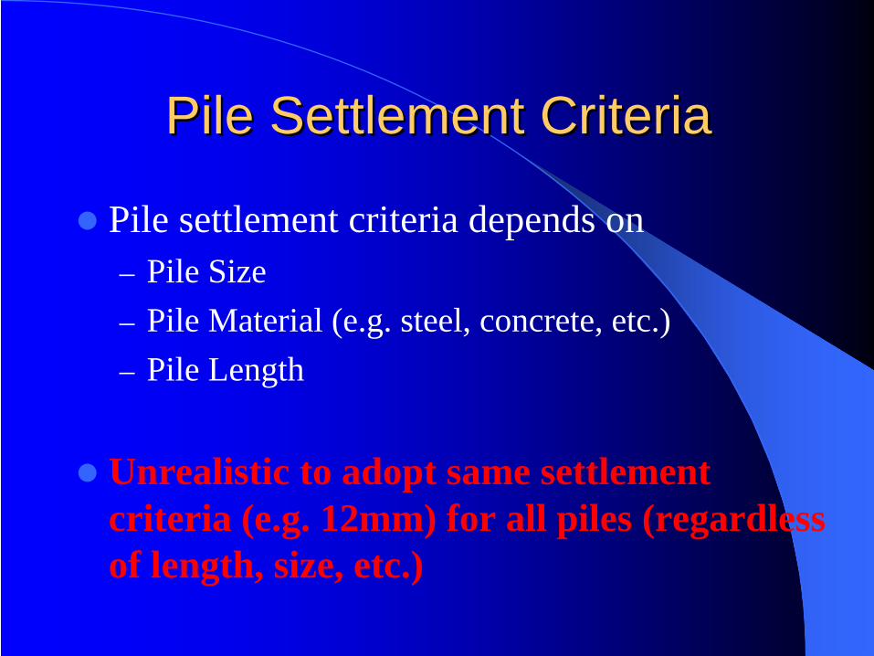
Pile Settlement CriteriaPile Settlement Criteria
Pile settlement criteria depends on– Pile Size– Pile Material (e.g. steel, concrete, etc.)– Pile Length
Unrealistic to adopt same settlement criteria (e.g. 12mm) for all piles (regardless of length, size, etc.)
Myths in Piling
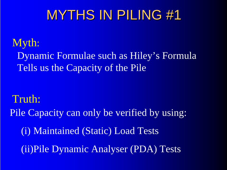
MYTHS IN PILING #1MYTHS IN PILING #1
Dynamic Formulae such as Hiley’s Formula Tells us the Capacity of the Pile
Pile Capacity can only be verified by using:
(i) Maintained (Static) Load Tests
(ii)Pile Dynamic Analyser (PDA) Tests
Myth:
Truth:
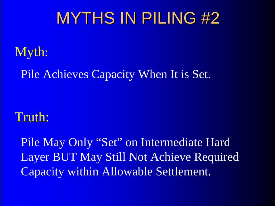
MYTHS IN PILING #2MYTHS IN PILING #2
Pile Achieves Capacity When It is Set.
Myth:
Truth:
Pile May Only “Set” on Intermediate Hard Layer BUT May Still Not Achieve Required Capacity within Allowable Settlement.
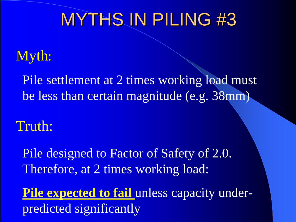
MYTHS IN PILING #3MYTHS IN PILING #3
Pile settlement at 2 times working load must be less than certain magnitude (e.g. 38mm)
Myth:
Truth:
Pile designed to Factor of Safety of 2.0. Therefore, at 2 times working load:
Pile expected to fail unless capacity under- predicted significantly
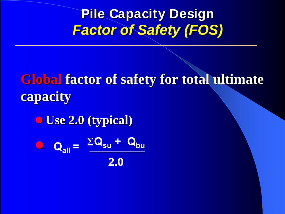
Pile Capacity DesignPile Capacity Design Factor of Safety (FOS)Factor of Safety (FOS)
GlobalGlobal factor of safety for total ultimate factor of safety for total ultimate capacitycapacity
Use 2.0 (typical)Use 2.0 (typical)
ΣQsu
+ Qbu
2.0Qall
=
CASE HISTORIESCASE HISTORIESCase 1: Structural distortion & distresses
Case 2: Distresses at houses
CASE HISTORY 1CASE HISTORY 1
Max. 20m Bouldery Fill on Undulating TerrainPlatform SettlementShort Piling ProblemsDowndrag on Piles
Distortion & Distresses on 40 Single/ 70 Double Storey Houses
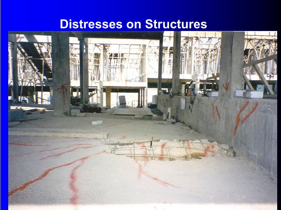
Distresses on Structures
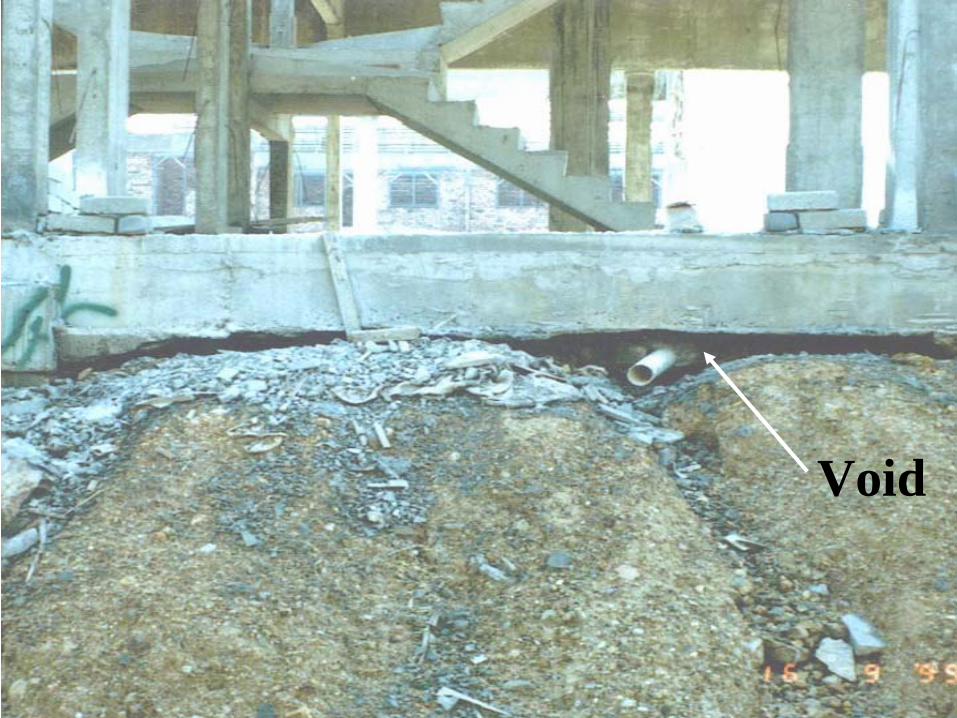
Void
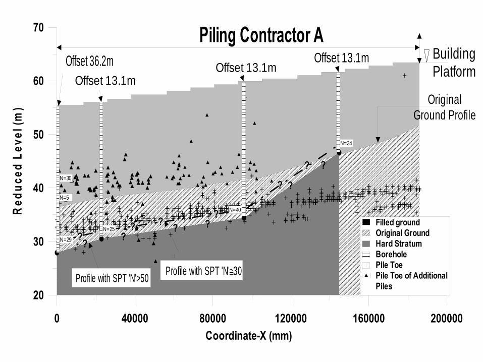
0 40000 80000 120000 160000 200000Coordinate-X (mm)
20
30
40
50
60
70R
educ
ed L
evel
(m)
Profile with SPT 'N'>50
Filled groundOriginal GroundHard StratumBoreholePile ToePile Toe of AdditionalPiles
OriginalGround Profile
BuildingPlatformOffset 13.1m
Offset 13.1m
N=25
N=40
N=34
Profile with SPT 'N'≅30
Offset 13.1m
N=29
N=30
N=5
Offset 36.2m
???
?? ?
??
?
?
?
?
Piling Contractor A
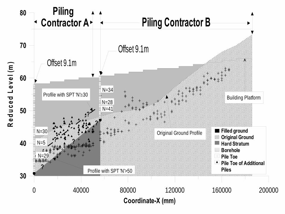
0 40000 80000 120000 160000 200000Coordinate-X (mm)
30
40
50
60
70
80R
educ
ed L
evel
(m)
Filled groundOriginal GroundHard StratumBoreholePile ToePile Toe of Additional PilesProfile with SPT 'N'>50
Building Platform
Original Ground ProfileN=30
N=34
N=28N=41
N=5
N=29
Profile with SPT 'N'≅30
Offset 9.1mOffset 9.1m
?
??
? ?
PilingContractor A Piling Contractor B
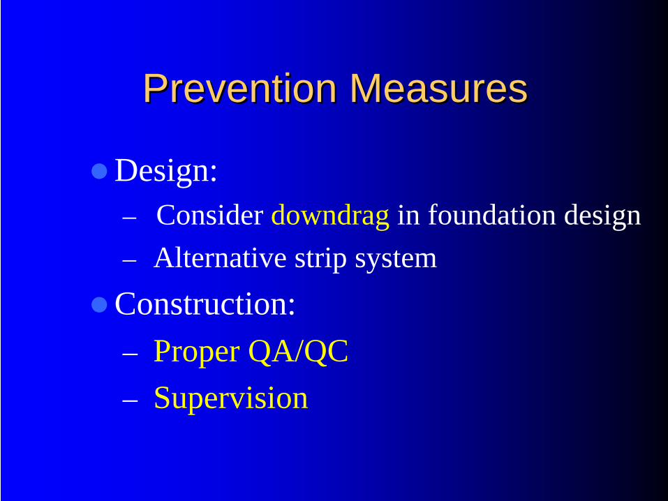
Prevention MeasuresPrevention Measures
Design:– Consider downdrag in foundation design– Alternative strip system
Construction: – Proper QA/QC – Supervision
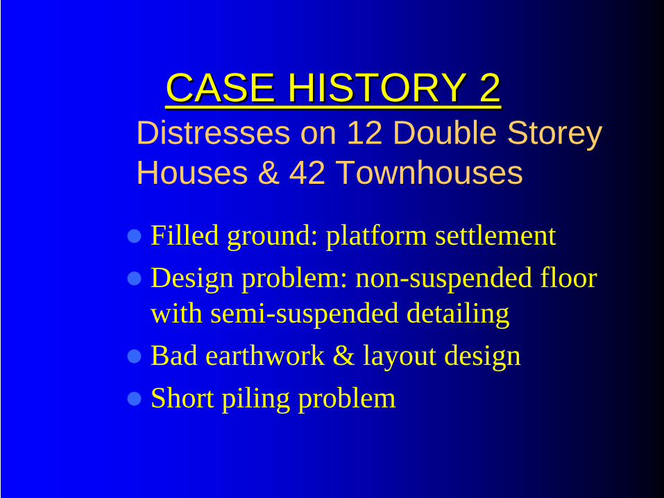
CASE HISTORY 2CASE HISTORY 2
Filled ground: platform settlementDesign problem: non-suspended floor with semi-suspended detailingBad earthwork & layout designShort piling problem
Distresses on 12 Double Storey Houses & 42 Townhouses
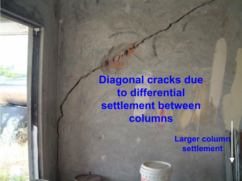
Diagonal cracks due to differential
settlement between columns
Larger column settlement
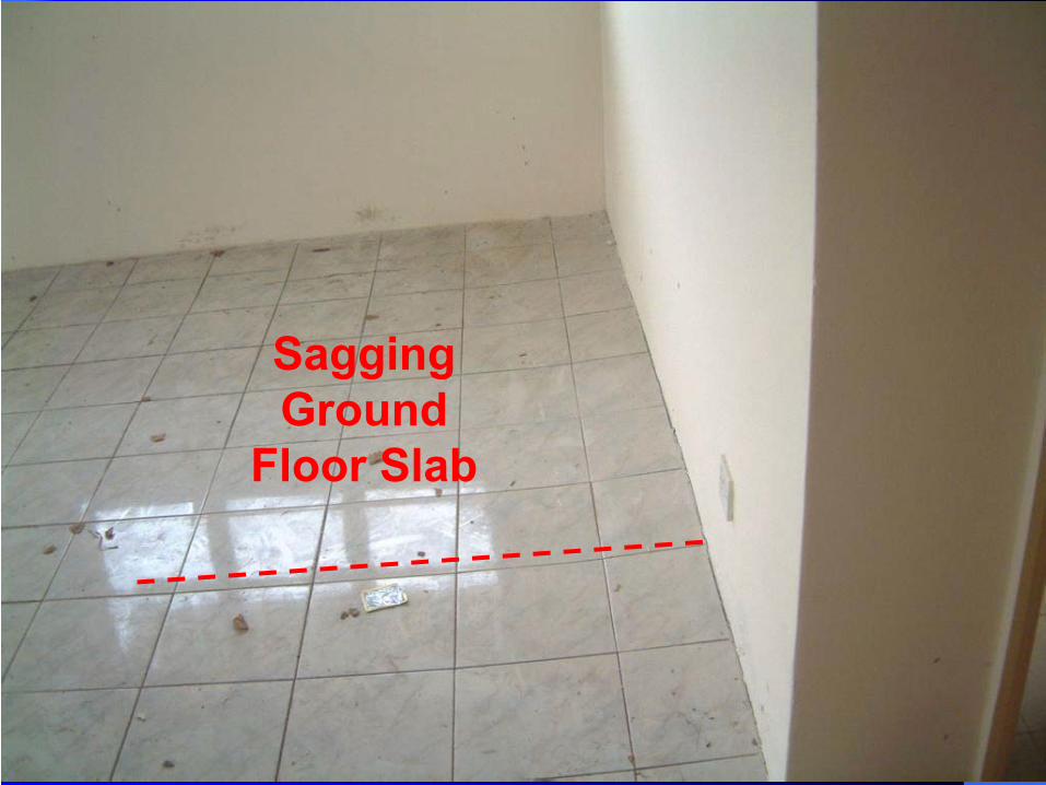
Sagging Ground
Floor Slab
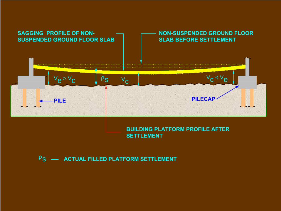
SAGGING PROFILE OF NON-
SUSPENDED GROUND FLOOR SLAB
NON-SUSPENDED GROUND FLOOR SLAB BEFORE SETTLEMENT
BUILDING PLATFORM PROFILE AFTER SETTLEMENT
PILE PILECAP
Ve > Vc Vc < VeVcρs
ρs ACTUAL FILLED PLATFORM SETTLEMENT
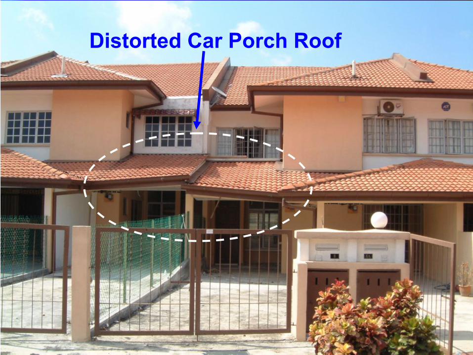
Distorted Car Porch Roof
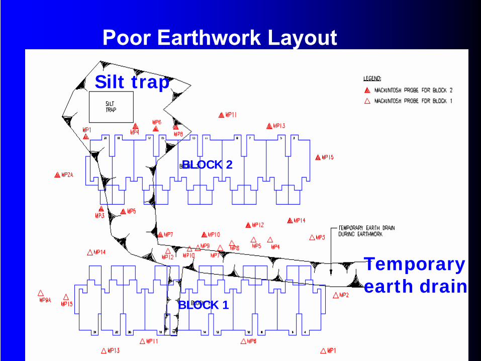
BLOCK 2
BLOCK 1
Silt trap
Temporary earth drain
Poor Earthwork Layout
Prevention MeasuresPrevention Measures
Planning: – Proper building layout planning to suit terrain
(eg. uniform fill thickness)– Sufficient SI
Design: – Consider filled platform settlement– Earthwork layout
Construction: – Supervision on earthwork & piling
SUMMARYSUMMARY
Importance of Preliminary Study
Understanding the Site Geology
Carry out Proper Subsurface Investigation that Suits the Terrain & Subsoil
Selection of Suitable Pile
Pile Design Concepts
SUMMARYSUMMARY
Importance of Piling Supervision
Typical Piling Problems Encountered
Present Some Case Histories

FERRARI ‘S PITSTOP WAS COMPLETED BY 15 MECHANICS (FUEL AND TYRES) IN 6.0 SECONDS FLAT.
54 PEOPLE TOOK PART IN THIS CONCERTED ACROBATIC JUMP.