Embed Size (px)
Citation preview

sensors
Article
Piezo-Resistive Properties of Bio-Based Sensor Yarn Made withSisal Fibre
Ahmed Abed 1,2,3,4,* , Zineb Samouh 1,2,3,4, Cédric Cochrane 1 , Francois Boussu 1 , Omar Cherkaoui 3,Reddad El Moznine 4 and Julien Vieillard 5
�����������������
Citation: Abed, A.; Samouh, Z.;
Cochrane, C.; Boussu, F.; Cherkaoui,
O.; El Moznine, R.; Vieillard, J.
Piezo-Resistive Properties of
Bio-Based Sensor Yarn Made with
Sisal Fibre. Sensors 2021, 21, 4083.
https://doi.org/10.3390/s21124083
Academic Editor: René M. Rossi
Received: 28 April 2021
Accepted: 11 June 2021
Published: 14 June 2021
Publisher’s Note: MDPI stays neutral
with regard to jurisdictional claims in
published maps and institutional affil-
iations.
Copyright: © 2021 by the authors.
Licensee MDPI, Basel, Switzerland.
This article is an open access article
distributed under the terms and
conditions of the Creative Commons
Attribution (CC BY) license (https://
creativecommons.org/licenses/by/
4.0/).
1 GEMTEX–Laboratoire de Génie et Matériaux Textiles, University of Lille, ENSAIT, F-59000 Lille, France;[email protected] (Z.S.); [email protected] (C.C.); [email protected] (F.B.)
2 Centrale Lille Institut, F-59000 Lille, France3 Laboratory REMTEX, ESITH, Route d’El Jadida, km 8, BP 7731 Oulfa, Casablanca, Morocco;
[email protected] Laboratory Physics of Condensed Matter (LPMC), Faculty of Science El Jadida, Chouaib Doukkali University,
El 24000 Jadida, Morocco; [email protected] COBRA (UMR 6014), UNIROUEN, INSA Rouen, Normandie Normandie Université, CNRS, 55 rue Saint
Germain, F-27000 Evreux, France; [email protected]* Correspondence: [email protected]; Tel.: +33-755-309-836
Abstract: In this work, a sensor yarn based on a natural sisal yarn containing a non-electro-conductivecore impregnated with PVA polymer and coated by PEDOT:PSS polymer as an electro-conductivesheath was investigated. The main objectives include the development of this new sensor yarn as afirst step. Then, we look towards the insertion of this sensor yarn into different woven structuresfollowed by the monitoring of the mechanical behaviour of composite materials made with thesefibrous reinforcements. The combined effect of the structural geometry and the number of PEDOT:PSScoating layers on the properties of the sensor yarns was investigated. It was found that the numberof PEDOT:PSS coating layers could strongly influence the electromechanical behaviours of the sensoryarns. Different methods of characterization were employed on strain-sensor yarns with two andfour coating layers of PEDOT:PSS. The piezo-resistive strain-sensor properties of these selectedcoating layers were evaluated. Cyclic stretching-releasing tests were also performed to investigatethe dynamic strain-sensing behavior. The obtained results indicated that gauge factor values canbe extracted in three strain regions for two and four coating layers, respectively. Moreover, thesestrain-sensor yarns showed accurate and stable sensor responses under cyclic conditions. Furthersworks are in progress to investigate the mechanism behind these first results of these sisal fibre-basedsensors.
Keywords: sisal yarn; piezo-resistive strain sensor; electromechanical properties; bio-based compos-ite; in-situ monitoring
1. Introduction
There exists an actual and forthcoming demand of “green composites”, due to increas-ing environmental aims to replace oil-dependent resource components with natural fibresfor the next generation of composite materials [1]. The natural fibrous reinforcement ofcomposite materials is often based on fabric structures (2D and 3D) made with bio-basedyarns [2]. Natural fibres have low density, biodegradable, and sustainable characteristicscompared to synthetic fibres [3,4]. Thus, the use of natural fibres is widely becomingthe subject of a large number of studies [5]. Among all of these studies, Corbin et al. [6]have developed a quasi-unidirectional woven fabric, based on hemp fibres impregnatedwith derivative sugar-based resin to produce a 100% bio-based composite material. Theresult of this research work has highlighted the relative higher performance of hemp-basedreinforcements compared to commercial flax-based reinforcements in terms of rigidities.
Sensors 2021, 21, 4083. https://doi.org/10.3390/s21124083 https://www.mdpi.com/journal/sensors

Sensors 2021, 21, 4083 2 of 15
In order to enhance the mechanical properties of natural fibre composites, it is im-portant to check these properties at each scale, especially at the yarn scale, due to theweather-dependent growth of vegetal fibres [7–9]. Consequently, variations in weatherconditions may lead to irregular fibre dimensions, which greatly affect the resulted lineardensity of the natural yarn and then can reduce or limit their use in composite materials.According to Mittal et al. [10], few studies have investigated the ageing effect of naturalfibres, their fatigue behaviour, and their failure mode when they are used into structuralcomposite material or during the textile technology processes. As suggested by Zenget al. [11], it may be useful to measure the effect of mechanical stresses applied on thesenatural fibrous reinforcements during the textile manufacturing process in order to checkhow the resulted properties are affected. Thus, it may be possible to insert sensing devicesinside the fibrous reinforcement that could behave similarly to the structural fibrous mate-rial and then help to monitor or detect locally the applied load while the textile materialis submitted to external mechanical stresses. As a result, these fibrous reinforcementswith their embedded sensing devices could be also impregnated to detect some damageinitiation of composite materials and ensure their health monitoring during their lifetimeduty.
Among all the existing sensing devices, strain gauges (or strain sensors) could be asolution for the evaluation of mechanical strain by electrical response [12]. However, theintroduction of these strain gauges inside a fibrous reinforcement poses a challenge duringtextile manufacture and could potentially be responsible for failure propagation inside thecomposite material, due to the difference of mechanical behaviours between the sensoryarn and the fibrous reinforcement. Hence why we have chosen to use the same materialfor the sensor yarn and the structural yarns to be used inside the fibrous reinforcement ofthe composite material.
Textile-based strain sensors that are made with yarns or fabrics have many properties,such as deformability and flexibility compared to rigid semi-conducting electronic andthin-film-based sensors. Strain-sensor yarns have many advantages, such as: (1) an easierinsertion into different textile structures by weaving or knitting technologies to providesensing function into the required directions; (2) the capacity to provide local measurementsof strain of the textile structure; and (3) the different locations of measurement in the textilereinforcement. Recent works have related that the manufacturing of strain-sensor yarnscan be achieved by the fibre spinning method [13,14] or by the coating method [15,16].Bilotti et al. developed an extrusion technique to produce strain-sensing multi-walledcarbon nanotubes containing thermoplastic polyurethane fibres [17]. Although the spinningmethods can produce sensor yarns with many properties, such as fatigue resistance andstretch-ability, these processes appear complicated and lead to higher cost in comparisonwith the coating techniques. Coating processes are used to functionalize textile substrateswith different advantages, such as the homogeneity and continuity of the coated layers,scalability, and low cost production [18]. Trifigny et al. [19] studied an approach whichconsists in the integration of piezo-resistive sensor made with E-glass yarns into a 3Dwoven fabric. This sensor yarn, based on PVA and PEDOT:PSS conductive polymers,was able to detect dynamic constraints applied on different warp yarns by sensing locallythe elongation. This approach has been very useful to identify the various parametersinfluencing on the mechanical properties of the 3D fibrous reinforcement during static anddynamic stresses.
The majority of these coated strain-sensor yarns are fabricated by using some conduc-tive materials such as graphite, graphene, and PEDOT:PSS. However, few works concerningthe coating of conductive polymers onto a natural multifilament substrate to fabricate yarnstrain sensors have been carried out. More attention should be paid on the heterogeneouscylindrical geometry rod with some grooves, cavities, and voids on the entire surface ofthe natural yarn [20]. Thus, it is of interest to investigate the fabrication of strain gaugesbased on sisal natural fibres coated with a PEDOT:PSS conductive polymer and their useas sensors inside composite materials.

Sensors 2021, 21, 4083 3 of 15
The sisal yarn used for this study is extracted from a plant (Agave Sisalana Perrine)that grows in Morocco. Sisal fibre contains some specific structural and geometrical charac-teristics, such as a high hydrophilic rate, a roughness surface, and low-angle microfibrils.The sisal fibre has also some interesting properties such as high toughness, low density,flexibility, and biodegradability [21,22]. These properties are required for fibre to be usedas a core for conductive coating polymers [23]. This natural fibre showed better adhesionand physical and mechanical properties when used as a reinforcement with PLA thermo-plastic resin for composite materials [24–26]. The increase of sisal fibre content improvesthe mechanical and dynamic properties of the composite material. However, the use ofsisal natural fibre as core for strain sensors can be limited due to their irregular geometry,chemical composition, and mechanical properties [27], which are mainly dependent onclimate conditions and species properties.
According to the literature review, it seems that the local and in-situ mechanicalbehaviour of natural fibrous reinforcements used in composite materials has not yet beenfully investigated. Therefore, in the present work, the durability of sisal fibres, used asreinforcement for bio-based composites, is evaluated. The investigation has been done tofind the optimized structure of the strain-sensor yarns with a PVA-coated sisal natural coreyarn and a PEDOT:PSS electro-conductive sheath. The physical and electro-mechanicalproperties of the sensor yarn are also presented and discussed.
2. Materials and Methods2.1. Material Selection
A sisal yarn, with an average diameter of 2.6 ± 0.35 mm and a linear density of3300 Tex, was provided by the Sonajute company. This was later extracted from a Mo-roccan agave plant. The sisal yarn consists of a set of monofilaments, which exhibiteda non-uniform network of overlapped fibres and little connected micro-pore structureswith a roughness surface. The average diameter of the monofilament was approximately200.56 ± 31.64 µm. This set of sisal monofilaments was twisted to 80 twists/metre in orderto improve the elasticity, stretchability, and strength of the resulting yarn.
Poly (vinyl alcohol) (PVA, Mw 9000–10,000, 78–82% hydrolysed) was purchased fromSigma–Aldrich. Poly (3,4-ethylenedioxythiophene): Poly (styrene sulfonate), also namedPEDOT:PSS, was supplied by the Heraeus company. PEDOT:PSS is expected to contributeto the electro-conductive sheath of the sensor yarns thanks to its prominent electricalconductivity, excellent mechanical strength, and thermal properties, even though thissample is well known to have more sensitivity to moisture hydration.
2.2. Preparation of PVA Solution
Polyvinyl alcohol (PVA) is a water-soluble aggregate polymer containing many alcoholfunctions. It has demonstrated several advantages such as good adhesion property, stability,and dispersing behaviour. In this study, 6 g of PVA (1.25 g/mL of density) particles wereput into de-ionized water (100 mL) for a duration of 1 h at 90 ◦C and stirred with a magneticstirrer until the complete dissolution of all the PVA particles.
2.3. Fabrication of Sensor Yarns
The sisal yarn was cleaned through successive sonication Soxhlet glassworks cleaningwith petroleum ether as a solvent over 3 h. This cleaning process was very useful to removeall the impurities trapped inside the natural sisal yarn, which can strongly influence theinterfacial adhesion properties. The pre-cleaned sisal yarn was then impregnated into aPVA solution for 30 s and dried at 90 ◦C for 15 min.
The PVA content adopted for this experiment was elected at 6.0 wt%. Then, theresulting PVA-coated sisal yarn was legated by two copper wires used as electrodes. Thediameter of the copper wires was 0.2 mm and the distance between these two ligaturedcopper wires was 30 mm. This distance value was chosen to be 10 times higher than thesisal yarn diameter to ensure more accurate measurement all along the yarn. To optimize

Sensors 2021, 21, 4083 4 of 15
the electrical contact between the PVA coated sisal yarn and the two ligatured copper wires,several PEDOT:PSS layers were coated and dried after each PEDOT:PSS layer deposit at110 ◦C for 5 min. Different coating steps were carried out carefully to obtain the desired andoptimized thickness of the electro-conductive PEDOT:PSS layers. It is important to statethat the PEDOT:PSS layers were deposited under the same conditions. All steps involvedin the fabrication of the sensor yarn are illustrated in Figure 1a,b.
Sensors 2021, 21, x FOR PEER REVIEW 4 of 16
diameter of the copper wires was 0.2 mm and the distance between these two ligatured copper wires was 30 mm. This distance value was chosen to be 10 times higher than the sisal yarn diameter to ensure more accurate measurement all along the yarn. To optimize the electrical contact between the PVA coated sisal yarn and the two ligatured copper wires, several PEDOT:PSS layers were coated and dried after each PEDOT:PSS layer de-posit at 110 °C for 5 min. Different coating steps were carried out carefully to obtain the desired and optimized thickness of the electro-conductive PEDOT:PSS layers. It is im-portant to state that the PEDOT:PSS layers were deposited under the same conditions. All steps involved in the fabrication of the sensor yarn are illustrated in Figure 1 a,b.
Figure 1. (a) Description of the fabrication process steps; (b) strain-sensor yarn.
In this study, we focused on two important factors such as the number of PEDOT:PSS coating layers as well as the geometry of the sensor yarns, in order to determine the opti-mal sheath thickness of the sensor yarn. The combined effects of these factors were inves-tigated to explore the desired performance of sensor yarns, such as an accurate sensing performance and an optimal geometry.
Different number of PEDOT:PSS layers from 1 to 4 were coated onto the PVA-coated sisal yarn surface. For each layer of PEDOT:PSS, the mass and the thickness of the sensor were measured (Table 1). As can be seen from Table 1, the uptake amount of PEDOT:PSS tends to increase when the number of coated layers increases.
For this study, two layers and four layers of PEDOT:PSS coatings were selected for further investigation, which correspond to the compromise of medium and higher weight ratios of PEDOT:PSS, respectively.
Figure 1. (a) Description of the fabrication process steps; (b) strain-sensor yarn.
In this study, we focused on two important factors such as the number of PEDOT:PSScoating layers as well as the geometry of the sensor yarns, in order to determine theoptimal sheath thickness of the sensor yarn. The combined effects of these factors wereinvestigated to explore the desired performance of sensor yarns, such as an accurate sensingperformance and an optimal geometry.
Different number of PEDOT:PSS layers from 1 to 4 were coated onto the PVA-coatedsisal yarn surface. For each layer of PEDOT:PSS, the mass and the thickness of the sensorwere measured (Table 1). As can be seen from Table 1, the uptake amount of PEDOT:PSStends to increase when the number of coated layers increases.
For this study, two layers and four layers of PEDOT:PSS coatings were selected forfurther investigation, which correspond to the compromise of medium and higher weightratios of PEDOT:PSS, respectively.

Sensors 2021, 21, 4083 5 of 15
Table 1. Mass and thickness of the PEDOT:PSS coating layers.
PEDOT:PSS CoatingProperties
Number of Coating Layers Mass (mg) Thickness (µm)
1 18.7 ± 0.9 47.0 ± 1.62 22.5 ± 1.3 67.0 ± 2.33 26.5 ± 3.4 81.0 ± 3.04 29.7 ± 4.1 90.0 ± 3.3
2.4. Characterization of the Strain-Sensor Yarns
Sensor yarns were investigated via physical and chemical characterization in terms ofmorphology and structure analysis, mechanical strength, and electromechanical behaviours,as well as tensile, conductivity, sensitivity, repeatability, and dynamic stability.
The morphology and microstructures of the sensor yarns were further characterizedby scanning electron microscopy (SEM). The SEM micrographs were obtained using a JEOLJEM-ARM200F HR setting. This analysis was performed on sensor yarns, before and aftermechanical tests, to investigate the effects of the resulted deformation on sensor yarns.
The tensile properties of the sensor yarn were analysed using the MTS Criterion (2/M)testing system. The samples were tested according to the ISO 2062:2009 standard, witha coupon length of 200 mm, and submitted to an initial 10 N preload at 200 mm·min−1.These measurements were carried out at each step of the fabrication of the sensor yarn.
The electrical conductivity of the yarn sensors was measured on a Keithley 3705Adigital multi-metre and calculated from the slope of I–U current–voltage curves. I–Ucharacteristic responses were collected with contact points between the two copper wiresof the sensor yarn and the two electrodes of the multi-metre device. The resistivity valuewas obtained in direct current (DC) mode with an applied voltage ranging between 0 Vand +10 V with a step of 0.1 V. Then the conductivity of samples was calculated usingEquation (1) [28]:
ρ =R × S
l(1)
where R, S, and l are the resistance, the surface area, and the thickness of the sensor yarn,respectively. Both values of the surface S and the thickness l were measured on samples byusing an optical microscope.
The electrical resistance changes (∆R/R0) of each sensor yarns were measured with adata acquisition system (National Instruments USB-6003) simultaneously on a tensile benchMTS Criterion. The real-time electrical resistance under a loading–unloading mechanicalcycle was recorded online by a computer connected to a DAQExpress Processing Softwaresynchronously and simultaneously. All the tests were performed at a strain rate speed equalto 200 mm·min−1 and different strain values up to strain at break. The electromechanicalresponse of the sensor yarn is quantitatively represented by the gauge factor (GF). Thislater can be obtained from the linear slope between the relative electrical resistance (∆R/R0)and the mechanical strain (ε), according to Equation (2):
∆RR0
= GF × ε (2)
3. Results and Discussions3.1. Morphological Properties of Sensor Yarn
Figure 2 shows the SEM image of the surface of pre-coating PVA. After the pre-coatingof the sisal fibres with the PVA layer, it can be observed that the cavities turned into asmooth and intact morphology. Moreover, the PVA-coated sisal yarn appears to be wellimpregnated, which could help with the deposit of the piezo-resistive sheet coating on itssurface.

Sensors 2021, 21, 4083 6 of 15
Sensors 2021, 21, x FOR PEER REVIEW 6 of 16
impregnated, which could help with the deposit of the piezo-resistive sheet coating on its surface.
Figure 2. (a) SEM image of the surface of sisal yarn pre-coated with PVA. (b) Selected red lines area.
The coating process of the PEDOT:PSS electro-conductive polymer aims at display-ing a homogeneous and continuous film structure with a dense thickness layer about few microns around the PVA-coated sisal yarn. Figure 3 shows the SEM images of the four PEDOT:PSS-coated layers compared to the sensor yarn fabricated with two PEDOT:PSS-coated layers. These images suggest a successful deposition through the addition of PEDOT:PSS layers, which indicates that the polymer chains were successfully penetrated and fixed into the PVA crosslinking network to form a semi-interpenetrated network structure [29]. Thus, the PEDOT:PSS layers may also indicate that there is a good adhesion onto the surface of the PVA-coated sisal yarn. Furthermore, the gaps within the strain-sensor yarns are totally reduced, and the electro-conductive layer became thicker.
Figure 3. SEM images: (a) sensor yarn for two coated layers of PEDOT:PSS and (b) selected red line area. (c) Sensor yarn for four coated layers of PEDOT:PSS and (d) selected red line area.
3.2. Electrical Characterization Figure 4 shows the evolution of the electrical conductivity as a function of the number
of PEDOT:PSS-coated layers from 0 to 5. It has been observed that the conductivity in-creased significantly when the number of PEDOT:PSS layers increased from two to four. The obtained conductivity value for 5 layers is very close to that for four layers. The value
(c) (d)
(a) (b)
(b) (a)
Figure 2. (a) SEM image of the surface of sisal yarn pre-coated with PVA. (b) Selected red lines area.
The coating process of the PEDOT:PSS electro-conductive polymer aims at displaying ahomogeneous and continuous film structure with a dense thickness layer about few micronsaround the PVA-coated sisal yarn. Figure 3 shows the SEM images of the four PEDOT:PSS-coated layers compared to the sensor yarn fabricated with two PEDOT:PSS-coated layers.These images suggest a successful deposition through the addition of PEDOT:PSS layers,which indicates that the polymer chains were successfully penetrated and fixed into thePVA crosslinking network to form a semi-interpenetrated network structure [29]. Thus,the PEDOT:PSS layers may also indicate that there is a good adhesion onto the surface ofthe PVA-coated sisal yarn. Furthermore, the gaps within the strain-sensor yarns are totallyreduced, and the electro-conductive layer became thicker.
Sensors 2021, 21, x FOR PEER REVIEW 6 of 16
impregnated, which could help with the deposit of the piezo-resistive sheet coating on its surface.
Figure 2. (a) SEM image of the surface of sisal yarn pre-coated with PVA. (b) Selected red lines area.
The coating process of the PEDOT:PSS electro-conductive polymer aims at display-ing a homogeneous and continuous film structure with a dense thickness layer about few microns around the PVA-coated sisal yarn. Figure 3 shows the SEM images of the four PEDOT:PSS-coated layers compared to the sensor yarn fabricated with two PEDOT:PSS-coated layers. These images suggest a successful deposition through the addition of PEDOT:PSS layers, which indicates that the polymer chains were successfully penetrated and fixed into the PVA crosslinking network to form a semi-interpenetrated network structure [29]. Thus, the PEDOT:PSS layers may also indicate that there is a good adhesion onto the surface of the PVA-coated sisal yarn. Furthermore, the gaps within the strain-sensor yarns are totally reduced, and the electro-conductive layer became thicker.
Figure 3. SEM images: (a) sensor yarn for two coated layers of PEDOT:PSS and (b) selected red line area. (c) Sensor yarn for four coated layers of PEDOT:PSS and (d) selected red line area.
3.2. Electrical Characterization Figure 4 shows the evolution of the electrical conductivity as a function of the number
of PEDOT:PSS-coated layers from 0 to 5. It has been observed that the conductivity in-creased significantly when the number of PEDOT:PSS layers increased from two to four. The obtained conductivity value for 5 layers is very close to that for four layers. The value
(c) (d)
(a) (b)
(b) (a)
Figure 3. SEM images: (a) sensor yarn for two coated layers of PEDOT:PSS and (b) selected red linearea. (c) Sensor yarn for four coated layers of PEDOT:PSS and (d) selected red line area.
3.2. Electrical Characterization
Figure 4 shows the evolution of the electrical conductivity as a function of the numberof PEDOT:PSS-coated layers from 0 to 5. It has been observed that the conductivityincreased significantly when the number of PEDOT:PSS layers increased from two to four.The obtained conductivity value for 5 layers is very close to that for four layers. The valueof the electrical conductivity increased from 176.71 mS.m-1 for the sensor yarn with twolayers of PEDOT:PSS to 752.4 mS.m-1 for the sensor yarn with four layers of PEDOT:PSS.

Sensors 2021, 21, 4083 7 of 15
Sensors 2021, 21, x FOR PEER REVIEW 7 of 16
of the electrical conductivity increased from 176.71 mS.m-1 for the sensor yarn with two layers of PEDOT:PSS to 752.4 mS.m-1 for the sensor yarn with four layers of PEDOT:PSS.
0 1 2 3 4 50
200
400
600
800
1000
Con
duct
ivity
(mS.
m-1)
Number of PEDOT: PSS coating layers Figure 4. Electrical conductivity of the sensor yarn as a function of the PEDOT:PSS-coated layers.
When the number of coated layers of PEDOT:PSS is higher than two layers, the elec-trical conductivity increases sharply, which is referred to as the electrical pseudo percola-tion threshold network range of the sensor yarns [30]. Moreover, the electrical pseudo percolation threshold depends on the processing method, conductive micro-sheet type, and polymer matrix [31]. Generally, it was reported that an elastic core with an electro-conductive sheath near to the electrical pseudo percolation threshold showed good sensi-tivity due to the presence of conductive networks [12]. Therefore, these low electro-con-ductive layers could be sufficient to maintain the flexible properties of the sensor yarns and then enhance the strain-sensing performances for specific electro-mechanical appli-cations.
Based on the above results, our study will be limited to the strain-sensor yarn with four coated layers of PEDOT:PSS in the following sections, due to the similar conductivity value obtained with 5 coating layers. This could be also an issue for reducing the amount of PEDOT:PSS used in manufacturing and consequently the material cost of the sensor yarns.
3.3. Mechanical Characterization 3.3.1. Mechanical Properties of Sensor Yarns
The mechanical performance of the sensor yarn was investigated by applying a ten-sile load until rupture. Figure 5 shows the stress–strain curves of different yarns which help to analyse respectively the mechanical behaviours of a sisal yarn alone, a PVA-coated sisal yarn, and two sisal sensor yarns with two and four PEDOT:PSS-coated layers.
Figure 4. Electrical conductivity of the sensor yarn as a function of the PEDOT:PSS-coated layers.
When the number of coated layers of PEDOT:PSS is higher than two layers, theelectrical conductivity increases sharply, which is referred to as the electrical pseudopercolation threshold network range of the sensor yarns [30]. Moreover, the electricalpseudo percolation threshold depends on the processing method, conductive micro-sheettype, and polymer matrix [31]. Generally, it was reported that an elastic core with anelectro-conductive sheath near to the electrical pseudo percolation threshold showed goodsensitivity due to the presence of conductive networks [12]. Therefore, these low electro-conductive layers could be sufficient to maintain the flexible properties of the sensoryarns and then enhance the strain-sensing performances for specific electro-mechanicalapplications.
Based on the above results, our study will be limited to the strain-sensor yarn withfour coated layers of PEDOT:PSS in the following sections, due to the similar conductivityvalue obtained with 5 coating layers. This could be also an issue for reducing the amountof PEDOT:PSS used in manufacturing and consequently the material cost of the sensoryarns.
3.3. Mechanical Characterization3.3.1. Mechanical Properties of Sensor Yarns
The mechanical performance of the sensor yarn was investigated by applying a tensileload until rupture. Figure 5 shows the stress–strain curves of different yarns which help toanalyse respectively the mechanical behaviours of a sisal yarn alone, a PVA-coated sisalyarn, and two sisal sensor yarns with two and four PEDOT:PSS-coated layers.
It can be seen that the strain-sensor yarn with highest number of PEDOT:PSS-coatedlayers (4) shows a slight increase of tensile strength. At the same time, the elongation atbreak increases with the increasing number of PEDOT:PSS-coated layers. Considering thisresult, it may be observed that the different number of coated layers applied on the sisalyarn did not affect the mechanical performance and behaviour of the initial material. Thestress–strain curves reveal quite similar behaviour for a single applied load, and it couldbe interesting to check it according to cyclic loads.
The maximum values of tensile strengths were found 129.7 ± 5.6 MPa, 135.8 ± 0.6 MPa,141.5 ± 0.6 MPa and 143.6 ± 1.3 MPa, respectively for the sisal yarns alone, PVA-pre-coatedsisal yarn and sisal sensor yarns with two and four coated layers of PEDOT:PSS.
Sensors 2021, 21, 4083 8 of 15Sensors 2021, 21, x FOR PEER REVIEW 8 of 16
0 1 2 3 4 5 6 7 8 90
20
40
60
80
100
120
140
160
Stre
ss (M
Pa)
Strain (%)
Sisal yarn Sisal yarn with PVA Sensor yarn with 2 PEDOT:PSS layers Sensor yarn with 4 PEDOT:PSS layers
Figure 5. Stress–strain curves of sisal yarn alone, sisal yarn with PVA pre-coating, and sensor yarns with two and four coating layers of PEDOT:PSS.
It can be seen that the strain-sensor yarn with highest number of PEDOT:PSS-coated layers (4) shows a slight increase of tensile strength. At the same time, the elongation at break increases with the increasing number of PEDOT:PSS-coated layers. Considering this result, it may be observed that the different number of coated layers applied on the sisal yarn did not affect the mechanical performance and behaviour of the initial material. The stress–strain curves reveal quite similar behaviour for a single applied load, and it could be interesting to check it according to cyclic loads.
The maximum values of tensile strengths were found 129.7± 5.6 MPa, 135.8± 0.6 MPa, 141.5± 0.6 MPa and 143.6± 1.3 MPa, respectively for the sisal yarns alone, PVA-pre-coated sisal yarn and sisal sensor yarns with two and four coated layers of PEDOT:PSS.
3.3.2. Impact of the Applied Strain on Sensor Yarns The effect of the applied strain on sensor yarns was investigated by SEM analysis.
The morphological surfaces of the different sensor yarns corresponding to different values of elongation (0%, 3% and 6%) are represented in Figure 6. It can be observed that some micro-cracks were formed and propagated on the PEDOT:PSS sheath while the sensor yarns are longitudinally elongated. The micro-cracks have occurred, which could be due to lower value of PEDOT:PSS sheath elasticity than in the sisal yarn core. Figure 6-c-d show some small micro-cracks when the sensor is extended to 3%, in comparison with 6% where further formation of larger micro-cracks can be observed. All these micro-cracks can strongly affect the change of the current conductive path of the PEDOT:PSS sheath and consequently its resistance values can also be modified [32]. Therefore, the variation of the micro-crack patterns from 3% to 6% of the strain of the sensor yarns could indicate a significant modification of their sensing performances.
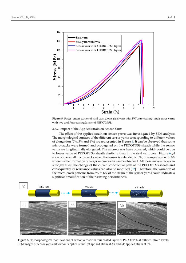
Figure 5. Stress–strain curves of sisal yarn alone, sisal yarn with PVA pre-coating, and sensor yarnswith two and four coating layers of PEDOT:PSS.
3.3.2. Impact of the Applied Strain on Sensor Yarns
The effect of the applied strain on sensor yarns was investigated by SEM analysis.The morphological surfaces of the different sensor yarns corresponding to different valuesof elongation (0%, 3% and 6%) are represented in Figure 6. It can be observed that somemicro-cracks were formed and propagated on the PEDOT:PSS sheath while the sensoryarns are longitudinally elongated. The micro-cracks have occurred, which could be dueto lower value of PEDOT:PSS sheath elasticity than in the sisal yarn core. Figure 6c,dshow some small micro-cracks when the sensor is extended to 3%, in comparison with 6%where further formation of larger micro-cracks can be observed. All these micro-cracks canstrongly affect the change of the current conductive path of the PEDOT:PSS sheath andconsequently its resistance values can also be modified [32]. Therefore, the variation ofthe micro-crack patterns from 3% to 6% of the strain of the sensor yarns could indicate asignificant modification of their sensing performances.
Sensors 2021, 21, x FOR PEER REVIEW 9 of 16
Figure 6. (a) morphological modifications of sensor yarns with four coated layers of PEDOT:PSS at different strain levels. SEM images of sensor yarns (b) without applied strain, (c) applied strain at 3% and (d) applied strain at 6%.
3.3.3. Mechanical Hysteresis The hysteresis properties of the sensor yarn with four coated layers of PEDOT:PSS
was investigated by cyclic repetitive loading and unloading under the stepwise increase deformations of 3% at a slow rate of 200 mm.min−1 as reported in Figure 7. For the applied strain, it is observed a reduction of stress softness, mechanical hysteresis and Young’s modulus. Thus, it is noticed that most mechanical hysteresis and stress softening were occurred in the first cycle. In our strain-sensor yarn applications, the mechanical hysteresis and stress softening were generated from the irreversible elongations during loading is-sue to the slip between PEDOT:PSS microsheets and PVA-coated sisal yarn core chains. During the first stretching cycle, the inner bonds and instable contacts, formed during the process fabrication of the strain-sensor yarn, brake irreversibly during the relaxation. Therefore, the 50th cycle and all the following elongations need less power to reach the same deformations.
0 1 2 3
0
10
20
30
Stre
ss (M
Pa)
Strain (%)
1st cycle 50th cycle 100th cycle
Figure 7. Mechanical hysteresis up to 3% strain for 1st, 50th and 100th cycles of sensor yarn with four coated layers of PEDOT:PSS.
(a)
(b) (c) (d)
Figure 6. (a) morphological modifications of sensor yarns with four coated layers of PEDOT:PSS at different strain levels.SEM images of sensor yarns (b) without applied strain, (c) applied strain at 3% and (d) applied strain at 6%.

Sensors 2021, 21, 4083 9 of 15
3.3.3. Mechanical Hysteresis
The hysteresis properties of the sensor yarn with four coated layers of PEDOT:PSSwas investigated by cyclic repetitive loading and unloading under the stepwise increasedeformations of 3% at a slow rate of 200 mm·min−1 as reported in Figure 7. For the appliedstrain, it is observed a reduction of stress softness, mechanical hysteresis and Young’smodulus. Thus, it is noticed that most mechanical hysteresis and stress softening wereoccurred in the first cycle. In our strain-sensor yarn applications, the mechanical hysteresisand stress softening were generated from the irreversible elongations during loadingissue to the slip between PEDOT:PSS microsheets and PVA-coated sisal yarn core chains.During the first stretching cycle, the inner bonds and instable contacts, formed duringthe process fabrication of the strain-sensor yarn, brake irreversibly during the relaxation.Therefore, the 50th cycle and all the following elongations need less power to reach thesame deformations.
Sensors 2021, 21, x FOR PEER REVIEW 9 of 16
Figure 6. (a) morphological modifications of sensor yarns with four coated layers of PEDOT:PSS at different strain levels. SEM images of sensor yarns (b) without applied strain, (c) applied strain at 3% and (d) applied strain at 6%.
3.3.3. Mechanical Hysteresis The hysteresis properties of the sensor yarn with four coated layers of PEDOT:PSS
was investigated by cyclic repetitive loading and unloading under the stepwise increase deformations of 3% at a slow rate of 200 mm.min−1 as reported in Figure 7. For the applied strain, it is observed a reduction of stress softness, mechanical hysteresis and Young’s modulus. Thus, it is noticed that most mechanical hysteresis and stress softening were occurred in the first cycle. In our strain-sensor yarn applications, the mechanical hysteresis and stress softening were generated from the irreversible elongations during loading is-sue to the slip between PEDOT:PSS microsheets and PVA-coated sisal yarn core chains. During the first stretching cycle, the inner bonds and instable contacts, formed during the process fabrication of the strain-sensor yarn, brake irreversibly during the relaxation. Therefore, the 50th cycle and all the following elongations need less power to reach the same deformations.
0 1 2 3
0
10
20
30
Stre
ss (M
Pa)
Strain (%)
1st cycle 50th cycle 100th cycle
Figure 7. Mechanical hysteresis up to 3% strain for 1st, 50th and 100th cycles of sensor yarn with four coated layers of PEDOT:PSS.
(a)
(b) (c) (d)
Figure 7. Mechanical hysteresis up to 3% strain for 1st, 50th and 100th cycles of sensor yarn withfour coated layers of PEDOT:PSS.
3.4. Electromechanical Properties of Sensor Yarn3.4.1. Uni-Axial Sensing Behaviour
The electromechanical properties of the strain-sensor yarns were also investigated.Mechanical cycles (stretching and releasing) were applied on strain-sensor yarn to measurethe resulting change in the electrical resistance.
Figure 8a,b shows the evolution of (∆R/R0) versus strain from 0 to 7% for sensor yarnswith two and four PEDOT:PSS-coated layers. As it can be observed, the relative variationsof resistance (∆R/R0) of the sensor yarns with two and four coated layers have increasedcontinuously with the applied strain, at a speed of 200 mm·min−1. However, the sensoryarn with two coated layers showed a failure at break for the maximum strain value of 7%.In contrast, the sensor yarn with four coated layers showed an elongation break up to 8%as shown in Figure 5.

Sensors 2021, 21, 4083 10 of 15
Sensors 2021, 21, x FOR PEER REVIEW 10 of 16
3.4. Electromechanical Properties of Sensor Yarn 3.4.1. Uni-Axial Sensing Behaviour
The electromechanical properties of the strain-sensor yarns were also investigated. Mechanical cycles (stretching and releasing) were applied on strain-sensor yarn to meas-ure the resulting change in the electrical resistance.
Figure 8 a,b shows the evolution of (∆R/R0) versus strain from 0 to 7% for sensor yarns with two and four PEDOT:PSS-coated layers. As it can be observed, the relative variations of resistance (ΔR/R0) of the sensor yarns with two and four coated layers have increased continuously with the applied strain, at a speed of 200 mm.min-1. However, the sensor yarn with two coated layers showed a failure at break for the maximum strain value of 7%. In contrast, the sensor yarn with four coated layers showed an elongation break up to 8% as shown in Figure 5.
0 1 2 3 4 5 6 7 8-2
0
2
4
6
8
10
12
14
16
18
20
GF=1.20
GF=2.68
GF=3.98
GF=2.04
GF=0.42
ΔR/R
0(%)
Strain (%)
2 coating layers of PEDOT:PSS 4 coating layers of PEDOT:PSS
GF=0.21
(a)
0 1 2 3 4 5 6 7 8-2
0
2
4
6
8
10
12
1416
18
20
ΔR/R
0(%
)
Strain (%)
2 coating layers of PEDOT:PSS 4 coating layers of PEDOT:PSS
(b) Figure 8. (a,b). Relative resistance variation with applied tensile strain for two and four coating layers.
The sensitivity of strain sensors is determined by the gauge factor (GF) which links the variation of resistivity to the elongation as represented in Equation (2) [33]. Thus, the (GF) gauge factor values of the different strain-sensor yarns have been calculated directly from stress–strain curves at different strain values.
In our case, the experimental data were fitted until the best linear fit was obtained according to Equation (2). A similar procedure was employed to extract the gauge factor (GF) values by Zheng et al. and Nakamura et al. [34,35].
The histogram presentation given in Figure 8b was very helpful in identifying the strain ranges with this linear behaviour. Figure 8a shows a better illustration for the choice of the more appropriate strain ranges. Three strain ranges were identified, and the ob-tained values of the gauge factor (GF) are given in Table 2.
Table 2. Electromechanical characteristics of sensor yarns: gauge factor (GF) value.
Samples: Sensor Yarn Strain Range: 0–2.5% Strain Range: 2.5–4.5% Strain Range: 4.5–7%
GF GF GF Two coating layers of
PEDOT:PSS 0.21 ± 0.01 (R2 = 0.791)
1.20 ± 0.01 (R2 = 0.982)
2.68 ± 0.01 (R2 = 0.985)
Four coating layers of PEDOT:PSS
0.42 ± 0.02 (R2 = 0.804)
2.04 ± 0.01 (R2 = 0.997)
3.98 ± 0.01 (R2 = 0.999)
Figure 8. (a,b). Relative resistance variation with applied tensile strain for two and four coating layers.
The sensitivity of strain sensors is determined by the gauge factor (GF) which linksthe variation of resistivity to the elongation as represented in Equation (2) [33]. Thus, the(GF) gauge factor values of the different strain-sensor yarns have been calculated directlyfrom stress–strain curves at different strain values.
In our case, the experimental data were fitted until the best linear fit was obtainedaccording to Equation (2). A similar procedure was employed to extract the gauge factor(GF) values by Zheng et al. and Nakamura et al. [34,35].
The histogram presentation given in Figure 8b was very helpful in identifying thestrain ranges with this linear behaviour. Figure 8a shows a better illustration for the choiceof the more appropriate strain ranges. Three strain ranges were identified, and the obtainedvalues of the gauge factor (GF) are given in Table 2.
Table 2. Electromechanical characteristics of sensor yarns: gauge factor (GF) value.
Samples: Sensor YarnStrain Range: 0–2.5% Strain Range: 2.5–4.5% Strain Range: 4.5–7%
GF GF GF
Two coating layers ofPEDOT:PSS
0.21 ± 0.01(R2 = 0.791)
1.20 ± 0.01(R2 = 0.982)
2.68 ± 0.01(R2 = 0.985)
Four coating layers ofPEDOT:PSS
0.42 ± 0.02(R2 = 0.804)
2.04 ± 0.01(R2 = 0.997)
3.98 ± 0.01(R2 = 0.999)
It can be seen that the sensor yarn with four coated layers of PEDOT:PSS exhibited twodifferent significant values of the gauge factor. The lower value, respectively 0.42 ± 0.02,corresponds to the first strain range between 0 and 2.5%, and the higher value, respectively3.98 ± 0.01, corresponds to the second strain range between 4.5 to 7%. Then, the sensorsensitivity highly increases with the applied deformations. For the lower thickness value,especially for two coated layers of PEDOT:PSS, a lower value of electrical conductivity isexpected, which can be explained by a lower gauge factor value at the same applied strainlevel. Regarding to the sensor yarn loadings, superior to the pseudo percolation threshold(i.e., four coating layers), the number of PEDOT:PSS layers are not enough to constitutea dense conductive network. When it has been elongated, the number of conductivepaths is enhanced significantly compared to the conductive fibre with lower PEDOT:PSSloadings due to the reinforced contacts between the conductive network structures. Thisenhancement of network structures shows the highest sensitivity to stretch, reflected by anincrease of gauge factor values at a high value of applied strain. Thus, the sensor yarns
Sensors 2021, 21, 4083 11 of 15
with four coated layers reveal a higher electrical conductivity and a high sensitivity toelongation.
3.4.2. Cyclic Strain YARN Sensing Properties
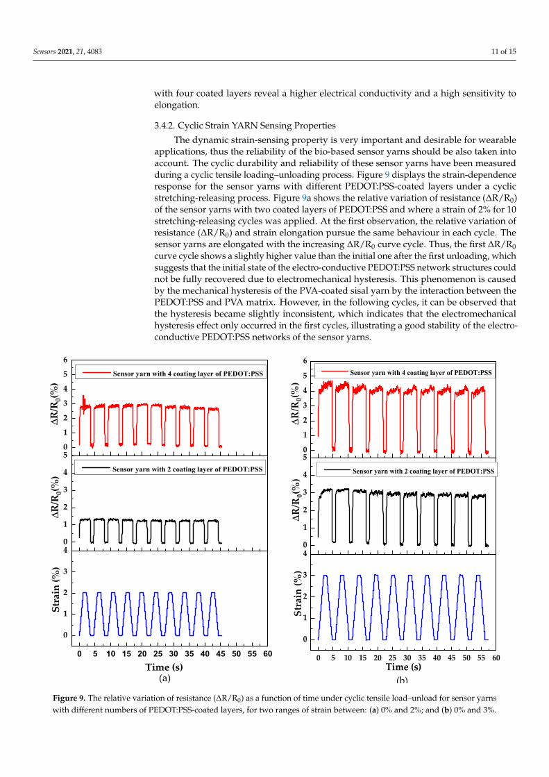
The dynamic strain-sensing property is very important and desirable for wearableapplications, thus the reliability of the bio-based sensor yarns should be also taken intoaccount. The cyclic durability and reliability of these sensor yarns have been measuredduring a cyclic tensile loading–unloading process. Figure 9 displays the strain-dependenceresponse for the sensor yarns with different PEDOT:PSS-coated layers under a cyclicstretching-releasing process. Figure 9a shows the relative variation of resistance (∆R/R0)of the sensor yarns with two coated layers of PEDOT:PSS and where a strain of 2% for 10stretching-releasing cycles was applied. At the first observation, the relative variation ofresistance (∆R/R0) and strain elongation pursue the same behaviour in each cycle. Thesensor yarns are elongated with the increasing ∆R/R0 curve cycle. Thus, the first ∆R/R0curve cycle shows a slightly higher value than the initial one after the first unloading, whichsuggests that the initial state of the electro-conductive PEDOT:PSS network structures couldnot be fully recovered due to electromechanical hysteresis. This phenomenon is causedby the mechanical hysteresis of the PVA-coated sisal yarn by the interaction between thePEDOT:PSS and PVA matrix. However, in the following cycles, it can be observed thatthe hysteresis became slightly inconsistent, which indicates that the electromechanicalhysteresis effect only occurred in the first cycles, illustrating a good stability of the electro-conductive PEDOT:PSS networks of the sensor yarns.
Sensors 2021, 21, x FOR PEER REVIEW 12 of 16
0 5 10 15 20 25 30 35 40 45 50 55 60
0
1
2
3
40
1
2
3
4
50
1
2
3
4
5
6
Stra
in (%
)
Time (s)(a)
ΔR/R
0(%)
Sensor yarn with 2 coating layer of PEDOT:PSS
ΔR/R
0(%)
Sensor yarn with 4 coating layer of PEDOT:PSS
0 5 10 15 20 25 30 35 40 45 50 55 60
0
1
2
3
40
1
2
3
4
50
1
2
3
4
5
6
Stra
in (%
)
Time (s)(b)
ΔR/R
0(%)
Sensor yarn with 2 coating layer of PEDOT:PSS
ΔR/R
0(%)
Sensor yarn with 4 coating layer of PEDOT:PSS
Figure 9. The relative variation of resistance (ΔR/R0) as a function of time under cyclic tensile load–unload for sensor yarns with different numbers of PEDOT:PSS-coated layers, for two ranges of strain between: (a) 0% and 2%; and (b) 0% and 3%.
To better investigate the distinction of the relative resistance ΔR/R0 with the loading–unloading strain shown in Figure 9, the ∆R/R0 of the two sensor yarns with two and four coated layers of PEDOT:PSS for the first three cycles with strains of 2% and 3% is pre-sented in Figure 10a,b, respectively. The ΔR/R0 curves follow the strain behaviour during the loading–unloading process. However, a fluctuation of the ΔR/R0 during the stretching-releasing deformation was observed, corresponding to the ‘shoulder’ behaviour of every loading–unloading cycle (as shown in Figure 10a and b). For the ΔR/R0 curve cycles, the shoulder value at the maximum is higher than the shoulder value at the minimum. This phenomenon might be related to the effect of the dimensionality of the sensor yarn.
Figure 9. The relative variation of resistance (∆R/R0) as a function of time under cyclic tensile load–unload for sensor yarnswith different numbers of PEDOT:PSS-coated layers, for two ranges of strain between: (a) 0% and 2%; and (b) 0% and 3%.

Sensors 2021, 21, 4083 12 of 15
Furthermore, it is notable that the peak values of the relative variation of resistance∆R/R0 exhibit higher values for the sensor yarns with four coated layers of PEDOT:PSSunder a strain of 2% (Figure 9a) compared to the sensing performances at 3% strain(Figure 9b). When the sensor yarns with four coated layers of PEDOT:PSS are extended tohigher strain values of up to 3%, PEDOT:PSS particles experience large elongation with thedeformation of the PVA-coated sisal yarn. A higher amount of these particles can lead tomore serious destruction of the PEDOT:PSS electro-conductive networks. Meanwhile, thedamage and construction of the electro-conductive network become very competitive andintense as more remarkable peaks of ∆R/R0 appeared.
To better investigate the distinction of the relative resistance ∆R/R0 with the loading–unloading strain shown in Figure 9, the ∆R/R0 of the two sensor yarns with two andfour coated layers of PEDOT:PSS for the first three cycles with strains of 2% and 3% ispresented in Figure 10a,b, respectively. The ∆R/R0 curves follow the strain behaviourduring the loading–unloading process. However, a fluctuation of the ∆R/R0 during thestretching-releasing deformation was observed, corresponding to the ‘shoulder’ behaviourof every loading–unloading cycle (as shown in Figure 10a,b). For the ∆R/R0 curve cycles,the shoulder value at the maximum is higher than the shoulder value at the minimum.This phenomenon might be related to the effect of the dimensionality of the sensor yarn.
Sensors 2021, 21, x FOR PEER REVIEW 13 of 16
0 2 4 6 8 10 12 14 16
0
1
2
3
4
5
Stra
in (%
)
Strain (%) Sensor with 2 coating layers of PEDOT: PSS Sensor with 4 coating layers of PEDOT: PSS
Time (s)(a)
0
1
2
3
4
5
6
ΔR/R
0(%
)
0
1
2
3
4
5
6
ΔR/R
0(%
)
0 2 4 6 8 10 12 14 16
0
1
2
3
4
5
Stra
in (%
)
Strain (%) Sensor with 2 coating layers of PEDOT: PSS Sensor with 4 coating layers of PEDOT: PSS
Time (s)(b)
0
1
2
3
4
5
6
ΔR/R
0(%
)
0
1
2
3
4
5
6
ΔR/R
0(%
)
Figure 10. The ∆R/R0 versus time between 0 and 16 min under loading–unloading cycles for sensor yarns with two and four coated layers of PEDOT:PSS with strains of (a) 2% and (b) 3%.
The ΔR/R0 signal outputs of 100 stretching–releasing cycles, performed at strain range values between 0–3% and at a strain speed of 200 mm.min−1, are shown in Figure 11a. A sharp drift down for the first initial cycles of the strain sensing response and then a stabilized trend can be observed, which is related to the constitution of an equilibrated state of the conductive networks after a period of adjustment [36]. Additionally, this could be due to the damage of the conductive networks and the hysteresis effect generated by the PVA viscoelastic matrix on the pre-coated sisal yarn. In the releasing mode, the varia-tion of resistance ΔR/R0 exhibits slightly lower values than in the stretching mode, which seems to be similar to other flexible conductive sensing devices [37]. Figure 11b shows the variation of ∆R/R0 at the maximum and minimum strain of 3% up to 100 cycles for sensor yarns with four coated layers of PEDOT:PSS. Thus, the sensor yarns with four coated lay-ers of PEDOT:PSS respond to cyclic stretching–releasing with efficient durability even af-ter several initial cycles with a strain of 3%. The results seem to indicate a slight decreasing trend value and a stable response after numerous loading–unloading cycles for the sensor yarns with four coated layers of PEDOT:PSS.
0 20 40 60 80 100
-5
0
5
10
0
1
2
3
4
-1
0
1
2
Strain 3%4 coating layers of PEDOT:PSS
ΔR/R
0(%)
Cycle number(a)
DR
/R0(
%)
ΔR/R
0(%
)
0 20 40 60 80 100
-5
0
5
10
ΔR/R
0 (%
)
Cycle number
ΔR/R0,max ΔR/R0,min
4 coating layers of PEDOT: PSS Strain 3%
(b) Figure 11. Multi-cycle elongation for the sensor yarns. (a) The ∆R/R0 of 100 stretching–releasing cycles with a maximum strain 3% at a slow rate of 200 mm.min−1 for sensor yarns with four coated layers of PEDOT:PSS; (b) The ∆R/R0 at strain 3% up to 100 cycles for strain-sensor yarns with four coated layers of PEDOT:PSS.
Figure 10. The ∆R/R0 versus time between 0 and 16 min under loading–unloading cycles for sensor yarns with two andfour coated layers of PEDOT:PSS with strains of (a) 2% and (b) 3%.
The ∆R/R0 signal outputs of 100 stretching–releasing cycles, performed at strain rangevalues between 0–3% and at a strain speed of 200 mm·min−1, are shown in Figure 11a.A sharp drift down for the first initial cycles of the strain sensing response and then astabilized trend can be observed, which is related to the constitution of an equilibratedstate of the conductive networks after a period of adjustment [36]. Additionally, this couldbe due to the damage of the conductive networks and the hysteresis effect generated by thePVA viscoelastic matrix on the pre-coated sisal yarn. In the releasing mode, the variationof resistance ∆R/R0 exhibits slightly lower values than in the stretching mode, whichseems to be similar to other flexible conductive sensing devices [37]. Figure 11b shows thevariation of ∆R/R0 at the maximum and minimum strain of 3% up to 100 cycles for sensoryarns with four coated layers of PEDOT:PSS. Thus, the sensor yarns with four coated layersof PEDOT:PSS respond to cyclic stretching–releasing with efficient durability even afterseveral initial cycles with a strain of 3%. The results seem to indicate a slight decreasingtrend value and a stable response after numerous loading–unloading cycles for the sensoryarns with four coated layers of PEDOT:PSS.

Sensors 2021, 21, 4083 13 of 15
Sensors 2021, 21, x FOR PEER REVIEW 13 of 16
0 2 4 6 8 10 12 14 16
0
1
2
3
4
5
Stra
in (%
)
Strain (%) Sensor with 2 coating layers of PEDOT: PSS Sensor with 4 coating layers of PEDOT: PSS
Time (s)(a)
0
1
2
3
4
5
6
ΔR/R
0(%
)
0
1
2
3
4
5
6
ΔR/R
0(%
)
0 2 4 6 8 10 12 14 16
0
1
2
3
4
5
Stra
in (%
)
Strain (%) Sensor with 2 coating layers of PEDOT: PSS Sensor with 4 coating layers of PEDOT: PSS
Time (s)(b)
0
1
2
3
4
5
6
ΔR/R
0(%
)
0
1
2
3
4
5
6
ΔR/R
0(%
)
Figure 10. The ∆R/R0 versus time between 0 and 16 min under loading–unloading cycles for sensor yarns with two and four coated layers of PEDOT:PSS with strains of (a) 2% and (b) 3%.
The ΔR/R0 signal outputs of 100 stretching–releasing cycles, performed at strain range values between 0–3% and at a strain speed of 200 mm.min−1, are shown in Figure 11a. A sharp drift down for the first initial cycles of the strain sensing response and then a stabilized trend can be observed, which is related to the constitution of an equilibrated state of the conductive networks after a period of adjustment [36]. Additionally, this could be due to the damage of the conductive networks and the hysteresis effect generated by the PVA viscoelastic matrix on the pre-coated sisal yarn. In the releasing mode, the varia-tion of resistance ΔR/R0 exhibits slightly lower values than in the stretching mode, which seems to be similar to other flexible conductive sensing devices [37]. Figure 11b shows the variation of ∆R/R0 at the maximum and minimum strain of 3% up to 100 cycles for sensor yarns with four coated layers of PEDOT:PSS. Thus, the sensor yarns with four coated lay-ers of PEDOT:PSS respond to cyclic stretching–releasing with efficient durability even af-ter several initial cycles with a strain of 3%. The results seem to indicate a slight decreasing trend value and a stable response after numerous loading–unloading cycles for the sensor yarns with four coated layers of PEDOT:PSS.
0 20 40 60 80 100
-5
0
5
10
0
1
2
3
4
-1
0
1
2
Strain 3%4 coating layers of PEDOT:PSS
ΔR/R
0(%)
Cycle number(a)
DR
/R0(
%)
ΔR/R
0(%
)
0 20 40 60 80 100
-5
0
5
10
ΔR/R
0 (%
)
Cycle number
ΔR/R0,max ΔR/R0,min
4 coating layers of PEDOT: PSS Strain 3%
(b) Figure 11. Multi-cycle elongation for the sensor yarns. (a) The ∆R/R0 of 100 stretching–releasing cycles with a maximum strain 3% at a slow rate of 200 mm.min−1 for sensor yarns with four coated layers of PEDOT:PSS; (b) The ∆R/R0 at strain 3% up to 100 cycles for strain-sensor yarns with four coated layers of PEDOT:PSS.
Figure 11. Multi-cycle elongation for the sensor yarns. (a) The ∆R/R0 of 100 stretching–releasing cycles with a maximumstrain 3% at a slow rate of 200 mm·min−1 for sensor yarns with four coated layers of PEDOT:PSS; (b) The ∆R/R0 at strain3% up to 100 cycles for strain-sensor yarns with four coated layers of PEDOT:PSS.
4. Conclusions
In this study, a sensor yarn based on a PVA-coated sisal natural fibre utilizing PE-DOT:PSS as electro-conductive sheath has been developed. These sensor yarns have beenmanufactured by using a coating technique, which has revealed several advantages, suchas the simplicity to implement and the capacity to adjust, at low cost, the various electrome-chanical properties by adjusting the number of coated layers of PEDOT:PSS on the sisalyarn.
The sensitivity of the PEDOT:PSS-coated layers, for a given length value of 30 mmapplied on the primary layer of pure PVA on the sisal yarn, has been improved thanks to theoptimization of the manufacturing process. The combined effects of these two importantmaterial and fabrication parameters were investigated. The sensor yarns manufacturedwith four PEDOT:PSS-coated layers showed much higher electrical conductivity values.
This study revealed that the gauge factor (GF) of the sensor yarns increased with theincreasing number of coated layers of PEDOT:PSS and reached an optimum value at fourlayers. In addition for the optimized four coated layers of PEDOT:PSS, the cyclic sensingbehaviours of the sensor yarn were investigated for 100 cycles at a strain speed equal to200 mm·min−1 and at an applied strain of 3%.
This sensor yarn has also showed high sensitivity with a gauge factor (GF) valueequal to 3.98 ± 0.01 and stable responses, proving their efficiency for use in the fibrousreinforcement of composite materials for their health monitoring purpose.
Further studies are to be carried out to assess the use and insertion of the preparedbio-based sensor yarn with four coated layers of PEDOT:PSS into a natural reinforcementfibre for green composite application.
Author Contributions: C.C., F.B. and R.E.M. defined the methodology and general concept and gavea guideline for this study; Z.S. and O.C. reviewed the data signals; J.V. performed experiments relatedto the SEM image analysis of the sisal yarn and sensor yarns; A.A. arranged the materials, performedall procedures, experiments, analysed data, and wrote the text of the manuscript. All authors haveread and agreed to the published version of the manuscript.
Funding: This research was funded by PHC Toubkal/19/83—Campus France: 41511ZF and CNRSTMoroccan agencies.
Institutional Review Board Statement: Not applicable.
Informed Consent Statement: Not applicable.

Sensors 2021, 21, 4083 14 of 15
Data Availability Statement: No data available online.
Acknowledgments: We would like to thank Christian Catel for his support in the preparation ofsisal yarns.
Conflicts of Interest: The authors declare no conflict of interest.
References1. Park, G.; Park, H. Structural Design and Test of Automobile Bonnet with Natural Flax Composite through Impact Damage
Analysis. Compos. Struct. 2018, 184, 800–806. [CrossRef]2. Kuo, W.-S.; Fang, J.; Lin, H.-W. Failure Behavior of 3D Woven Composites under Transverse Shear. Compos. Part A Appl. Sci.
Manuf. 2003, 34, 561–575. [CrossRef]3. Bourmaud, A.; Beaugrand, J.; Shah, D.U.; Placet, V.; Baley, C. Towards the Design of High-Performance Plant Fibre Composites.
Prog. Mater. Sci. 2018, 97, 347–408. [CrossRef]4. Getu, D.; Nallamothu, R.B.; Masresha, M.; Nallamothu, S.K.; Nallamothu, A.K. Production and Characterization of Bamboo
and Sisal Fiber Reinforced Hybrid Composite for Interior Automotive Body Application. Mater. Today Proc. 2021, 38, 2853–2860.[CrossRef]
5. Lansiaux, H.; Soulat, D.; Boussu, F.; Labanieh, A.R. Development and Multiscale Characterization of 3D Warp Interlock FlaxFabrics with Different Woven Architectures for Composite Applications. Fibers 2020, 8, 15. [CrossRef]
6. Corbin, A.-C.; Sala, B.; Soulat, D.; Ferreira, M.; Labanieh, A.-R.; Placet, V. Development of Quasi-Unidirectional Fabrics withHemp Fiber: A Competitive Reinforcement for Composite Materials. J. Compos. Mater. 2021, 55, 551–564. [CrossRef]
7. Omrani, F.; Wang, P.; Soulat, D.; Ferreira, M. Mechanical Properties of Flax-Fibre-Reinforced Preforms and Composites: Influenceof the Type of Yarns on Multi-Scale Characterisations. Compos. Part A Appl. Sci. Manuf. 2017, 93, 72–81. [CrossRef]
8. Corbin, A.-C.; Soulat, D.; Ferreira, M.; Labanieh, A.-R.; Gabrion, X.; Malécot, P.; Placet, V. Towards Hemp Fabrics for High-Performance Composites: Influence of Weave Pattern and Features. Compos. Part B Eng. 2020, 181, 107582. [CrossRef]
9. Baley, C.; Gomina, M.; Breard, J.; Bourmaud, A.; Davies, P. Variability of Mechanical Properties of Flax Fibres for CompositeReinforcement. A Review. Ind. Crop. Prod. 2020, 145, 111984. [CrossRef]
10. Mittal, V.; Saini, R.; Sinha, S. Natural Fiber-Mediated Epoxy Composites–A Review. Compos. Part B Eng. 2016, 99, 425–435.[CrossRef]
11. Zeng, W.; Shu, L.; Li, Q.; Chen, S.; Wang, F.; Tao, X.-M. Fiber-Based Wearable Electronics: A Review of Materials, Fabrication,Devices, and Applications. Adv. Mater. 2014, 26, 5310–5336. [CrossRef]
12. Pang, C.; Lee, G.-Y.; Kim, T.; Kim, S.M.; Kim, H.N.; Ahn, S.-H.; Suh, K.-Y. A Flexible and Highly Sensitive Strain-Gauge SensorUsing Reversible Interlocking of Nanofibres. Nat. Mater. 2012, 11, 795–801. [CrossRef] [PubMed]
13. Zeng, Z.; Chen, M.; Jin, H.; Li, W.; Xue, X.; Zhou, L.; Pei, Y.; Zhang, H.; Zhang, Z. Thin and Flexible Multi-Walled CarbonNanotube/Waterborne Polyurethane Composites with High-Performance Electromagnetic Interference Shielding. Carbon 2016,96, 768–777. [CrossRef]
14. Tang, X.-Z.; Mu, C.; Zhu, W.; Yan, X.; Hu, X.; Yang, J. Flexible Polyurethane Composites Prepared by Incorporation ofPolyethylenimine-Modified Slightly Reduced Graphene Oxide. Carbon 2016, 98, 432–440. [CrossRef]
15. Tian, M.; Hu, X.; Qu, L.; Zhu, S.; Sun, Y.; Han, G. Versatile and Ductile Cotton Fabric Achieved via Layer-by-Layer Self-Assemblyby Consecutive Adsorption of Graphene Doped PEDOT: PSS and Chitosan. Carbon 2016, 96, 1166–1174. [CrossRef]
16. Cheng, Y.; Wang, R.; Sun, J.; Gao, L. A Stretchable and Highly Sensitive Graphene-Based Fiber for Sensing Tensile Strain, Bending,and Torsion. Adv. Mater. 2015, 27, 7365–7371. [CrossRef]
17. Bilotti, E.; Zhang, R.; Deng, H.; Baxendale, M.; Peijs, T. Fabrication and Property Prediction of Conductive and Strain SensingTPU/CNT Nanocomposite Fibres. J. Mater. Chem. 2010, 20, 9449. [CrossRef]
18. Wang, H.; Liu, Z.; Ding, J.; Lepró, X.; Fang, S.; Jiang, N.; Yuan, N.; Wang, R.; Yin, Q.; Lv, W.; et al. Downsized Sheath-CoreConducting Fibers for Weavable Superelastic Wires, Biosensors, Supercapacitors, and Strain Sensors. Adv. Mater. 2016, 28,4998–5007. [CrossRef]
19. Trifigny, N.; Kelly, F.; Cochrane, C.; Boussu, F.; Koncar, V.; Soulat, D. PEDOT:PSS-Based Piezo-Resistive Sensors Appliedto Reinforcement Glass Fibres for in Situ Measurement during the Composite Material Weaving Process. Sensors 2013, 13,10749–10764. [CrossRef]
20. Khadir, A.; Negarestani, M.; Ghiasinejad, H. Low-Cost Sisal Fibers/Polypyrrole/Polyaniline Biosorbent for Sequestration ofReactive Orange 5 from Aqueous Solutions. J. Environ. Chem. Eng. 2020, 8, 103956. [CrossRef]
21. Joseph, P.V.; Joseph, K.; Thomas, S. Effect of Processing Variables on the Mechanical Properties of Sisal-fiber-ReinforcedPolypropylene Composites. Compos. Sci. Technol. 1999, 59, 1625–1640. [CrossRef]
22. Venkateshwaran, N.; ElayaPerumal, A.; Alavudeen, A.; Thiruchitrambalam, M. Mechanical and Water Absorption Behaviour ofBanana/Sisal Reinforced Hybrid Composites. Mater. Des. 2011, 32, 4017–4021. [CrossRef]
23. Senthilkumar, K.; Saba, N.; Rajini, N.; Chandrasekar, M.; Jawaid, M.; Siengchin, S.; Alotman, O.Y. Mechanical PropertiesEvaluation of Sisal Fibre Reinforced Polymer Composites: A Review. Constr. Build. Mater. 2018, 174, 713–729. [CrossRef]
24. Reddy, G.V.; Naidu, S.V.; Rani, T.S. A Study on Hardness and Flexural Properties of Kapok/Sisal Composites. J. Reinf. Plast.Compos. 2009, 28, 2035–2044. [CrossRef]

Sensors 2021, 21, 4083 15 of 15
25. Sanjay, M.R.; Madhu, P.; Jawaid, M.; Senthamaraikannan, P.; Senthil, S.; Pradeep, S. Characterization and Properties of NaturalFiber Polymer Composites: A Comprehensive Review. J. Clean. Prod. 2018, 172, 566–581. [CrossRef]
26. Samouh, Z.; Molnar, K.; Boussu, F.; Cherkaoui, O.; El Moznine, R. Mechanical and Thermal Characterization of Sisal FiberReinforced Polylactic Acid Composites. Polym. Adv. Technol. 2019, 30, 529–537. [CrossRef]
27. Hashmi, S.A.R.; Naik, A.; Chand, N.; Sharma, J.; Sharma, P. Development of Environment Friendly Hybrid Layered Sisal–Glass–Epoxy Composites. Compos. Interfaces 2011, 18, 671–683. [CrossRef]
28. Costa, P.; Silva, J.; Sencadas, V.; Simoes, R.; Viana, J.C.; Lanceros-Méndez, S. Mechanical, Electrical and Electro-MechanicalProperties of Thermoplastic Elastomer Styrene–Butadiene–Styrene/Multiwall Carbon Nanotubes Composites. J. Mater. Sci. 2013,48, 1172–1179. [CrossRef]
29. Zhang, Y.-F.; Guo, M.-M.; Zhang, Y.; Tang, C.Y.; Jiang, C.; Dong, Y.; Law, W.-C.; Du, F.-P. Flexible, Stretchable and ConductivePVA/PEDOT:PSS Composite Hydrogels Prepared by SIPN Strategy. Polym. Test. 2020, 81, 106213. [CrossRef]
30. Zhao, J.; Dai, K.; Liu, C.; Zheng, G.; Wang, B.; Liu, C.; Chen, J.; Shen, C. A Comparison between Strain Sensing Behaviors ofCarbon Black/Polypropylene and Carbon Nanotubes/Polypropylene Electrically Conductive Composites. Compos. Part A Appl.Sci. Manuf. 2013, 48, 129–136. [CrossRef]
31. Sadasivuni, K.K.; Ponnamma, D.; Thomas, S.; Grohens, Y. Evolution from Graphite to Graphene Elastomer Composites. Prog.Polym. Sci. 2014, 39, 749–780. [CrossRef]
32. Balima, F.; Le Floch, S.; Adessi, C.; Cerqueira, T.F.T.; Blanchard, N.; Arenal, R.; Brûlet, A.; Marques, M.A.L.; Botti, S.; San-Miguel,A. Radial Collapse of Carbon Nanotubes for Conductivity Optimized Polymer Composites. Carbon 2016, 106, 64–73. [CrossRef]
33. Jeong, Y.R.; Park, H.; Jin, S.W.; Hong, S.Y.; Lee, S.-S.; Ha, J.S. Highly Stretchable and Sensitive Strain Sensors Using FragmentizedGraphene Foam. Adv. Funct. Mater. 2015, 25, 4228–4236. [CrossRef]
34. Zheng, Y.; Li, Y.; Dai, K.; Liu, M.; Zhou, K.; Zheng, G.; Liu, C.; Shen, C. Conductive Thermoplastic Polyurethane Composites withTunable Piezoresistivity by Modulating the Filler Dimensionality for Flexible Strain Sensors. Compos. Part A Appl. Sci. Manuf.2017, 101, 41–49. [CrossRef]
35. Nakamura, A.; Hamanishi, T.; Kawakami, S.; Takeda, M. A Piezo-Resistive Graphene Strain Sensor with a Hollow CylindricalGeometry. Mater. Sci. Eng. B 2017, 219, 20–27. [CrossRef]
36. Duan, L.; Fu, S.; Deng, H.; Zhang, Q.; Wang, K.; Chen, F.; Fu, Q. The Resistivity–Strain Behavior of Conductive PolymerComposites: Stability and Sensitivity. J. Mater. Chem. A 2014, 2, 17085–17098. [CrossRef]
37. Deng, H.; Ji, M.; Yan, D.; Fu, S.; Duan, L.; Zhang, M.; Fu, Q. Towards Tunable Resistivity–Strain Behavior through Constructionof Oriented and Selectively Distributed Conductive Networks in Conductive Polymer Composites. J. Mater. Chem. A 2014, 2,10048–10058. [CrossRef]