Embed Size (px)
Citation preview
Page # 1
PHYSICSFORMULA BOOKLET - GYAAN SUTRA
INDEXS.No. Topic Page No.
1. Unit and Dimension 22. Rectilinear Motion 3 – 43. Projectile Motion & Vector 5 – 54. Relavitve Motion 5 – 75. Newton’s Laws of Motion 7 – 96. Friction 9 – 97. Work, Power & Energy 10 – 118. Circular Motion 11 – 149. Centre of Mass 14 – 1810. Rigid Body Dynamics 18 – 2511. Simple Harmonic Motion 26 – 2812. Sting Wave 29 – 3113. Heat & Thermodynamics 31 – 3714. Electrostatics 37 – 4015. Current Electricity 41 – 4716. Capacitance 47 – 5117. Alternating Current 52 – 5418. Magnetic Effect of Current & Magnetic
force on charge 54 – 56
19. Electromagnetic Induction 56 – 5920. Geometrical Optics 59 – 6621. Modern Physics 67 – 7022. Wave Optics 70 – 7323. Gravitation 73 – 7524. Fluid Mechanics & Properties of Matter 75 – 7725. Sound Wave 77 – 7926. Electro Magnetic Waves 79 – 8027. Error and Measurement 80 – 8128. Principle of Communication 82 – 8329. Semiconductor 84 – 85

Page # 2
PHYSICSFORMULA BOOKLET - GYAAN SUTRAA
UNIT AND DIMENSIONSUnit :Measurement of any physical quantity is expressed in terms of aninternationally accepted certain basic standard called unit.
* Fundamental Units.
S.No. Physical Quantity SI Unit Symbol
1 Length Metre m
2 Mass Kilogram Kg
3 Time Second S
4 Electric Current Ampere A
5 Temperature Kelvin K
6 Luminous Intensity Candela Cd
7 Amount of Substance Mole mol * Supplementary Units :
S.No. Physical Quantity SI Unit Symbol
1 Plane Angle radian r
2 Solid Angle Steradian Sr
* Metric Prefixes :
S.No. Prefix Sym bol Value
1 Centi c 10–2
2 M ili m 10–3
3 M icro µ 10–6
4 Nano n 10–9
5 Pico p 10–12
6 K ilo K 103
7 M ega M 106
Page # 3
RECTILINEAR MOTION
Average Velocity (in an interval) :
vav = v = <v> = takentimeTotal
ntdisplacemeTotal = trr if
Average Speed (in an interval)
Average Speed = taken timeTotaltravelled distanceTotal
Instantaneous Velocity (at an instant) :
instv
=
trlim
0t
Average acceleration (in an interval):
ava
= tv
= tvv if
Instantaneous Acceleration (at an instant):
a
= dtvd
=
tvlim
0t
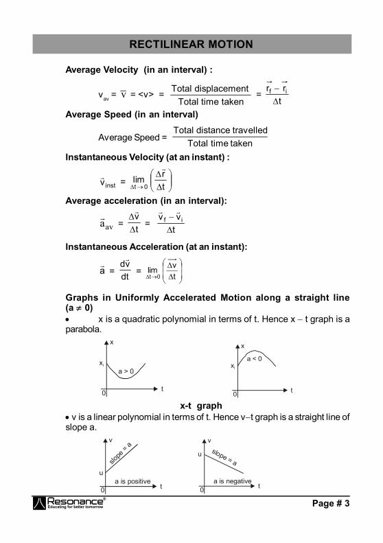
Graphs in Uniformly Accelerated Motion along a straight line(a 0) x is a quadratic polynomial in terms of t. Hence x t graph is aparabola.
xi
x
a > 0
t0
xi
x
a < 0
t0
x-t graph v is a linear polynomial in terms of t. Hence vt graph is a straight line ofslope a.
v
ua is positive
slope
= a
t0
v
u
a is negative
slope = a
t0
Page # 4
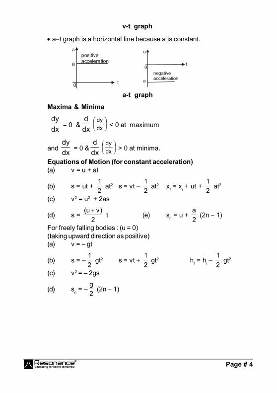
v-t graph
at graph is a horizontal line because a is constant.
a
apositiveacceleration
t0a
a
negativeacceleration
0
a-t graph
Maxima & Minima
dxdy
= 0 & dxd
dxdy
< 0 at maximum
and dxdy
= 0 & dxd
dxdy
> 0 at minima.
Equations of Motion (for constant acceleration)(a) v = u + at
(b) s = ut + 21
at2 s = vt 21
at2 xf = xi + ut + 21
at2
(c) v2 = u2 + 2as
(d) s = 2
)vu( t (e) sn = u +
2a
(2n 1)
For freely falling bodies : (u = 0)(taking upward direction as positive)(a) v = – gt
(b) s = –21
gt2 s = vt 21
gt2 hf = hi – 21
gt2
(c) v2 = – 2gs
(d) sn = –2g
(2n 1)
Page # 5
PROJECTILE MOTION & VECTORS
Time of flight : T = gsinu2
Horizontal range : R = g
2sinu2
Maximum height : H = g2sinu 22
Trajectory equation (equation of path) :
y = x tan – 22
2
cosu2gx
= x tan (1 – Rx
)
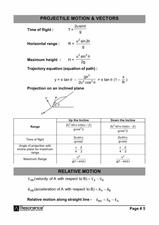
Projection on an inclined plane
y
x
Up the Incline Down the Incline
Range
2
2
cosg)cos(sinu2
2
2
cosg)cos(sinu2
Time of flight
cosgsinu2
cosgsinu2
Angle of projection with incline plane for maximum
range 24
24
Maximum Range )sin1(g
u2
)sin1(gu2
RELATIVE MOTION
BAAB vv)BtorespectwithAofvelocity(v
BAAB aa)BtorespectwithAofonaccelerati(a
Relative motion along straight line - ABBA xxx

Page # 6
CROSSING RIVERA boat or man in a river always moves in the direction of resultant velocityof velocity of boat (or man) and velocity of river flow.
1. Shortest Time :
Velocity along the river, vx = vR.Velocity perpendicular to the river, vf = vmR
The net speed is given by vm = 2R
2mR vv
2. Shortest Path :velocity along the river, vx = 0
and velocity perpendicular to river vy = 2R
2mR vv
The net speed is given by vm = 2R
2mR vv
at an angle of 90º with the river direction.velocity vy is used only to cross the river,

Page # 7
therefore time to cross the river, t = yv
d = 2
R2mR vv
d
and velocity vx is zero, therefore, in this case the drift should be zero. vR – vmR sin = 0 or vR = vmR sin
or = sin–1
mR
R
vv
RAIN PROBLEMS
Rmv
= Rv
– mv
or vRm = 2m
2R vv
NEWTON'S LAWS OF MOTION1. From third law of motion
BAAB FF
ABF = Force on A due to B
BAF = Force on B due to AA
2. From second law of motion
Fx = dtdPx = max Fy =
dtdPy
= may Fz = dtdPz = maz
5. WEIGHING MACHINE :A weighing machine does not measure the weight but measures theforce exerted by object on its upper surface.
6. SPRING FORCE xkF
x is displacement of the free end from its natural length or deformationof the spring where K = spring constant.
7. SPRING PROPERTY K × = constant= Natural length of spring.
8. If spring is cut into two in the ratio m : n then spring constant is givenby
1 = nm
m
; 2 = nm
.n
k = k11 = k22

Page # 8
For series combination of springs .......k1
k1
k1
21eq
For parallel combination of spring keq = k1 + k2 + k3 ............
9. SPRING BALANCE:It does not measure the weight. t measures the force exerted by theobject at the hook.Remember :
Vp = 1 2V V2
aP = 1 2a a2
11.21
12
mmg)mm(a
21
21mm
gmm2T
12. WEDGE CONSTRAINT:
Components of velocity along perpendicular direction to the contactplane of the two objects is always equal if there is no deformationsand they remain in contact.
Page # 9
13. NEWTON’S LAW FOR A SYSTEM
ext 1 1 2 2 3 3F m a m a m a ......
extF
Net external force on the system.m1, m2, m3 are the masses of the objects of the system and
1 2 3a ,a ,a
are the acceleration of the objects respectively..
14. NEWTON’S LAW FOR NON INERTIAL FRAME :
amFF PseudoalRe
Net sum of real and pseudo force is taken in the resultant force.
a
= Acceleration of the particle in the non inertial frame
PseudoF
= m Framea
(a) Inertial reference frame: Frame of reference moving with con-stant velocity.(b) Non-inertial reference frame: A frame of reference moving withnon-zero acceleration.
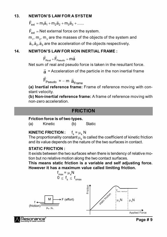
FRICTIONFriction force is of two types.(a) Kinetic (b) Static
KINETIC FRICTION : fk = k NThe proportionality constant k is called the coefficient of kinetic frictionand its value depends on the nature of the two surfaces in contact.
STATIC FRICTION :It exists between the two surfaces when there is tendency of relative mo-tion but no relative motion along the two contact surfaces.This means static friction is a variable and self adjusting force.However it has a maximum value called limiting friction.
fmax = sN0 fs fsmax
Fric
tion
Applied Force
static
fricti
on
f static maximum
sN kN

Page # 10
WORK, POWER & ENERGYWORK DONE BY CONSTANT FORCE :
W = F
. S
WORK DONE BY MULTIPLE FORCESF
= F
1 + F
2 + F
3 + .....
W = [F
] . S
...(i)
W = F
1 . S
+ F
2 . S
+ F
3 . S
+ .....or W = W1 + W2 + W3 + ..........
WORK DONE BY A VARIABLE FORCE
dW = F.ds
RELATION BETWEEN MOMENTUM AND KINETIC ENERGY
K = m2p2
and P = Km2 ; P = linear momentum
POTENTIAL ENERGY
2
1
2
1
r
r
U
UrdFdU
i.e.,2
1
r2 1 r
U U F dr W
WrdFUr
CONSERVATIVE FORCES
F= – rU
WORK-ENERGY THEOREMWC + WNC + WPS = K
Modified Form of Work-Energy TheoremWC = UWNC + WPS = K + UWNC + WPS = E

Page # 11
POWER
The average power ( P or pav) delivered by an agent is given by P or
pav = t
W
dtSdFP
=
dtSdF
= F
. v
CIRCULAR MOTION
1. Average angular velocity av = 12
12
tt
= t
2. Instantaneous angular velocity = dtd
3. Average angular acceleration av = 12
12
tt
= t
4. Instantaneous angular acceleration = dtd
=
dd
5. Relation between speed and angular velocity v = r and rv
7. Tangential acceleration (rate of change of speed)
at = dtdV
= r dtd
= dtdr
8. Radial or normal or centripetal acceleration ar = r
v2= 2r
9. Total acceleration rt aaa
a = (at
2 + ar2)1/2
ra ca
ata
vor
P
OWhere ra t
and var

Page # 12
10. Angular acceleration
= dt
d
(Non-uniform circular motion)
ACWRotation
12. Radius of curvature R = a
v2
= F
mv2
If y is a function of x. i.e. y = f(x) R =
2
2
2/32
dxyd
dxdy1
13. Normal reaction of road on a concave bridge
N = mg cos + r
mv2
N
Vmg
mgcosconcave bridge
O
14. Normal reaction on a convex bridge
N = mg cos – r
mv2
N V
mg
mgcosconvex bridge
O
15. Skidding of vehicle on a level road vsafe gr
16. Skidding of an object on a rotating platform max = r/g
Page # 13
17. Bending of cyclist tan = rgv 2
18. Banking of road without friction tan = rgv 2
19. Banking of road with friction
tan1tan
rgv2
20. Maximum also minimum safe speed on a banked frictional road
Vmax 2/1
)tan1()tan(rg
Vmin 1/ 2
rg (tan )(1 tan )
21. Centrifugal force (pseudo force) f = m2 r, acts outwards when theparticle itself is taken as a frame.
22. Effect of earths rotation on apparent weight N = mg – mR2 cos2 ;
where latitude at a place
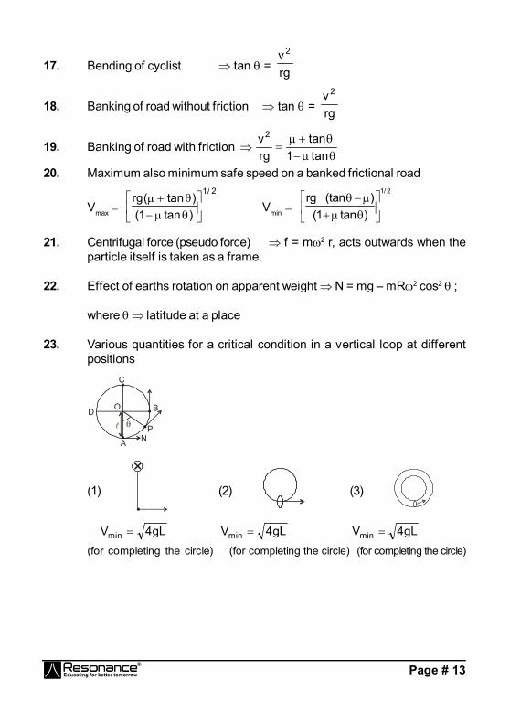
23. Various quantities for a critical condition in a vertical loop at differentpositions
C
B
PNA
D
O
(1)
×(2) (3)
gL4Vmin gL4Vmin gL4Vmin
(for completing the circle) (for completing the circle) (for completing the circle)
Page # 14
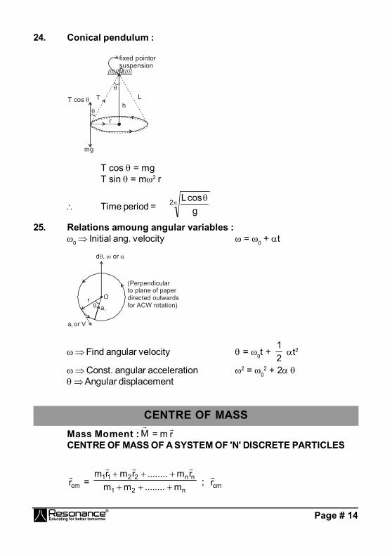
24. Conical pendulum :
/////////////
fixed pointorsuspensionO
hT L
r
mg
T cos
T cos = mgT sin = m2 r
Time period = 2g
cosL
25. Relations amoung angular variables :0 Initial ang. velocity = 0 + t
a or Vt
ar
Or
d , or
(Perpendicular to plane of paper directed outwards for ACW rotation)
Find angular velocity = 0t + 21
t2
Const. angular acceleration 2 = 02 + 2
Angular displacement
CENTRE OF MASSMass Moment : M
= m r
CENTRE OF MASS OF A SYSTEM OF 'N' DISCRETE PARTICLES
cmr
= n21
nn2211
m........mmrm........rmrm
; cmr

Page # 15
=
n
1ii
n
1iii
m
rm
cmr
= M1
n
1iii rm
CENTRE OF MASS OF A CONTINUOUS MASS DISTRIBUTION
xcm =
dm
dmx, ycm =
dm
dmy, zcm =
dm
dmz
dm = M (mass of the body)
CENTRE OF MASS OF SOME COMMON SYSTEMS A system of two point masses m1 r1 = m2 r2
The centre of mass lies closer to the heavier mass.
Rectangular plate (By symmetry)
xc = 2b
yc = 2L
Page # 16
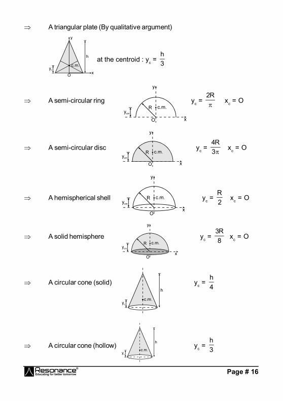
A triangular plate (By qualitative argument)
at the centroid : yc = 3h
A semi-circular ring yc = R2
xc = O
A semi-circular disc yc = 3R4
xc = O
A hemispherical shell yc = 2R
xc = O
A solid hemisphere yc = 8R3
xc = O
A circular cone (solid) yc = 4h
A circular cone (hollow) yc = 3h

Page # 17
MOTION OF CENTRE OF MASS AND CONSERVATION OF MOMENTUM:Velocity of centre of mass of system
cmv
= Mdtdrm..............
dtdrm
dtdrm
dtdrm n
n3
32
21
1
= M
vm..........vmvmvm nn332211
SystemP = M cmvAcceleration of centre of mass of system
cma
= M
dtdvm..............
dtdvm
dtdvm
dtdvm n
n3
32
21
1
= M
am..........amamam nn332211
= M
systemonforceNet =
MForceernalintNetForceExternalNet
= M
ForceExternalNet
extF
= M cma
IMPULSEImpulse of a force F action on a body is defined as :-
J
= f
i
t
tFdt PΔJ
(impulse - momentum theorem)
Important points :1. Gravitational force and spring force are always non-impulsive.2. An impulsive force can only be balanced by another impulsive force.
COEFFICIENT OF RESTITUTION (e)
e = ndeformatioofpulseImnreformatioofpulseIm
=
dtF
dtF
d
r
= s impactoflinealongapproachofVelocityimpactoflinealongseparationofVelocity

Page # 18
(a) e = 1 Impulse of Reformation = Impulse of Deformation Velocity of separation = Velocity of approach Kinetic Energy may be conserved Elastic collision.
(b) e = 0 Impulse of Reformation = 0 Velocity of separation = 0 Kinetic Energy is not conserved Perfectly Inelastic collision.
(c) 0 < e < 1 Impulse of Reformation < Impulse of Deformation Velocity of separation < Velocity of approach
Kinetic Energy is not conserved Inelastic collision.
VARIABLE MASS SYSTEM :If a mass is added or ejected from a system, at rate kg/s and relativevelocity relv
(w.r.t. the system), then the force exerted by this mass
on the system has magnitude relv
.
Thrust Force ( tF
)
dtdmvF relt
Rocket propulsion :If gravity is ignored and initial velocity of the rocket u = 0;
v = v r ln
mm0 .
RIGID BODY DYNAMICS
1. RIGID BODY :
A VA
VB2
1
B
VBsin2
VAcos1
VAsin1
VBcos2
A
B
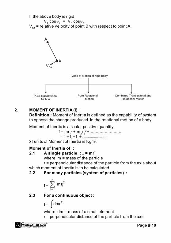
Page # 19
If the above body is rigidVA cos 1 = VB cos 2
VBA = relative velocity of point B with respect to point A.
VBA
B
A
Pure Translational Motion
Pure Rotational Motion
Types of Motion of rigid body
Combined Translational and Rotational Motion
2. MOMENT OF INERTIA (I) :Definition : Moment of Inertia is defined as the capability of systemto oppose the change produced in the rotational motion of a body.
Moment of Inertia is a scalar positive quantity. = mr1
2 + m2 r22 +.........................
= + + +.........................
S units of Moment of Inertia is Kgm2.
Moment of Inertia of :2.1 A single particle : = mr2
where m = mass of the particler = perpendicular distance of the particle from the axis about
which moment of Inertia is to be calculated2.2 For many particles (system of particles) :
=
n
1i
2iirm
2.3 For a continuous object :
= 2dmr
where dm = mass of a small elementr = perpendicular distance of the particle from the axis
Page # 20
2.4 For a larger object :
= elementd
where d = moment of inertia of a small element
3. TWO IMPORTANT THEOREMS ON MOMENT OF INERTIA :3.1 Perpendicular Axis Theorem
[Only applicable to plane lamina (that means for 2-D objects only)].
z = x + y (when object is in x-y plane).
3.2 Parallel Axis Theorem(Applicable to any type of object): = cm + Md2
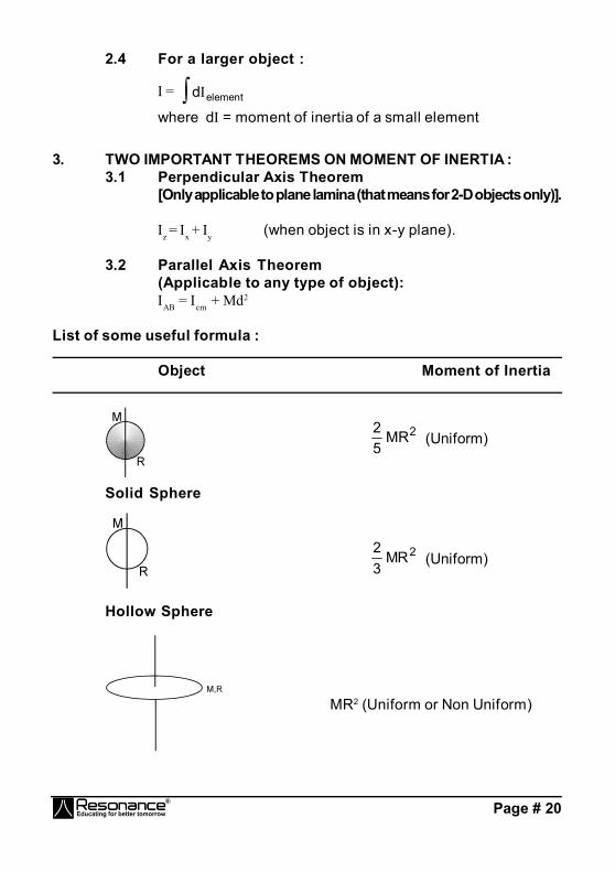
List of some useful formula :
Object Moment of Inertia
2MR52
(Uniform)
Solid Sphere
2MR32
(Uniform)
Hollow Sphere
MR2 (Uniform or Non Uniform)

Page # 21
Ring.
2
MR2 (Uniform)
Disc
MR2 (Uniform or Non Uniform)
Hollow cylinder
2MR2
(Uniform)
Solid cylinder
3ML2
(Uniform)
12ML2
(Uniform)

Page # 22
3m2 2
(Uniform)
AB = CD = EF = 12
Ma2 (Uniform)
Square Plate
6Ma2
(Uniform)
Square Plate
= 12
)ba(M 22 (Uniform)
Rectangular Plate
12)ba(M 22 (Uniform)
Cuboid
Page # 23
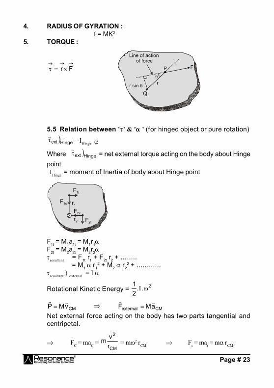
4. RADIUS OF GYRATION : = MK2
5. TORQUE :
Fr
5.5 Relation between '' & '' (for hinged object or pure rotation)Hingeext
= Hinge
Where Hingeext
= net external torque acting on the body about Hingepoint Hinge = moment of Inertia of body about Hinge point
x
F1t
F1c
F2t
F2c
r1
r2
F1t = M1a1t = M1r1F2t = M2a2t = M2r2resultant = F1t r1 + F2t r2 + ........
= M1 r12 + M2 r2
2 + ............resultant ) external =
Rotational Kinetic Energy = 2..21
CMvMP
CMexternal aMF
Net external force acting on the body has two parts tangential andcentripetal.
FC = maC = CM
2
rvm = m2 rCM Ft = mat = m rCM

Page # 24
6. ROTATIONAL EQUILIBRIUM :For translational equilibrium.
0Fx ............. (i)
and 0Fy ............. (ii)The condition of rotational equilibrium is
0z
7. ANGULAR MOMENTUM (L
)7.1 Angular momentum of a particle about a point.
L = Pr
L = rpsin
L
= r × P
L
= P× r
7.3 Angular momentum of a rigid body rotating about fixed axis :
HL = H
LH = angular momentum of object about axis H.IH = Moment of Inertia of rigid object about axis H. = angular velocity of the object.
7.4 Conservation of Angular MomentumAngular momentum of a particle or a system remains constant if ext = 0 about that point or axis of rotation.
7.5 Relation between Torque and Angular Momentum
=
dtLd
Torque is change in angular momentum

Page # 25
7.6 Impulse of Torque :
Jdt J Change in angular momentum.
For a rigid body, the distance between the particles remain unchangedduring its motion i.e. rP/Q = constantFor velocities
Q
Pr r
with respect to Q
Q
Pr
wr
with respect to ground
VQ
VQ
cosrV2rVV Q22
QPFor acceleration :
, , are same about every point of the body (or any other pointoutside which is rigidly attached to the body).Dynamics :
cmcm , cmext aMF
cmsystem vMP
,
Total K.E. = 2cmMv21
+ 2cm2
1
Angular momentum axis AB = L
about C.M. + L
of C.M. about ABAB
cmcmcmAB vMrL

Page # 26
SIMPLE HARMONIC MOTIONS.H.M.F = – kxGeneral equation of S.H.M. is x = A sin (t + ); (t + ) is phase of themotion and is initial phase of the motion.
Angular Frequency () : = T2
= 2f
Time period (T) : T = 2
= km2
mk
Speed : 22 xAv Acceleration : a = 2x
Kinetic Energy (KE) : 21
mv2 = 21
m2 (A2 – x2) =21
k (A2 – x2)
Potential Energy (PE) :21
Kx2
Total Mechanical Energy (TME)
= K.E. + P.E. = 21
k (A2 – x2) + 21
Kx2 = 21
KA2 (which is constant)
SPRING-MASS SYSTEM
(1)smooth surface
k
m
T = 2km
(2)
T = K
2 where = )m(m
mm
21
21
known as reduced mass
Page # 27
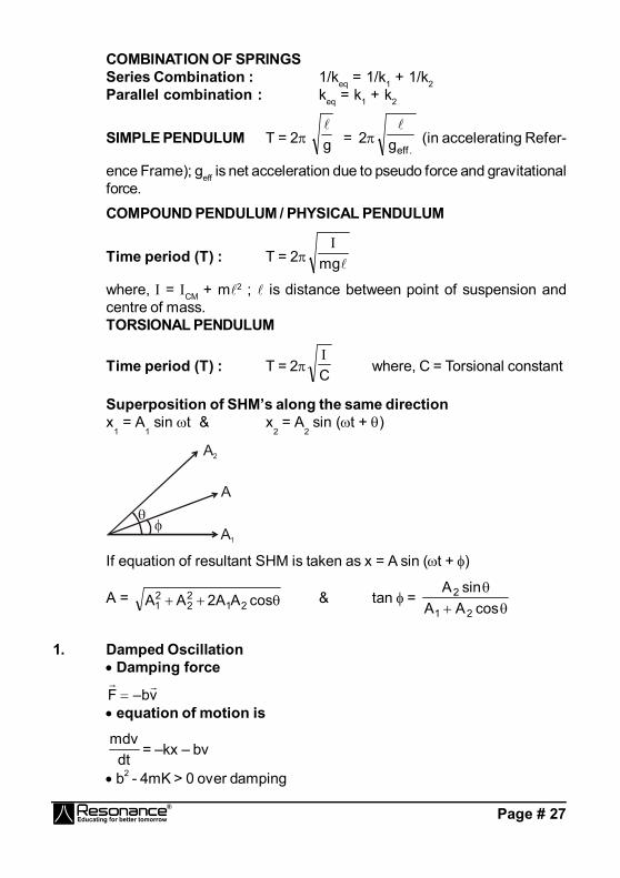
COMBINATION OF SPRINGSSeries Combination : 1/keq = 1/k1 + 1/k2Parallel combination : keq = k1 + k2
SIMPLE PENDULUM T = 2 g
= 2.effg
(in accelerating Refer-
ence Frame); geff is net acceleration due to pseudo force and gravitationalforce.
COMPOUND PENDULUM / PHYSICAL PENDULUM
Time period (T) : T = 2 mg
where, = CM + m2 ; is distance between point of suspension andcentre of mass.TORSIONAL PENDULUM
Time period (T) : T = 2 C
where, C = Torsional constant
Superposition of SHM’s along the same directionx
1 = A
1 sin t & x
2 = A
2 sin (t + )
A2
A
A1
If equation of resultant SHM is taken as x = A sin (t + )
A = cosAA2AA 2122
21 & tan =
cosAAsinA
21
2
1. Damped Oscillation Damping force
vb–F
equation of motion is
dtmdv
= –kx – bv
b2 - 4mK > 0 over damping

Page # 28
b2 - 4mK = 0 critical damping b2 - 4mK < 0 under damping For small damping the solution is of the form.
x = m2/bt–0eA sin [1t + ], where
2
m2b–
mk'
For small b
angular frequency 0,m/k'
Amplitude m2bt–
0eAA
l
Energy E (t) = 21
KA2 m/bt–e
Quality factor or Q value , Q = |E|E2
= Y2'
where , 2
2
m4b.
mk' ,
m2b
Y
2. Forced Oscillations And ResonanceExternal Force F(t) = F0 cos d tx(t) = A cos (dt + )
0
22 2 2 2 2d d
FA
m b
and 0
d 0
vtan
x
(a) Small Damping 0
2 2d
FA
m
(b) Driving Frequency Close to Natural Frequency 0
d
FA
b
Page # 29
STRING WAVESGENERAL EQUATION OF WAVE MOTION :
2
2
ty
= v2
2
2
xy
y(x,t) = f (t ± vx
)
where, y (x, t) should be finite everywhere.
f
vxt represents wave travelling in – ve x-axis.
f
vxt represents wave travelling in + ve x-axis.
y = A sin (t ± kx + )
TERMS RELATED TO WAVE MOTION ( FOR 1-D PROGRESSIVESINE WAVE )(e) Wave number (or propagation constant) (k) :
k = 2/ = v
(rad m–1)
(f) Phase of wave : The argument of harmonic function (t ± kx + )is called phase of the wave. Phase difference () : difference in phases of two particles at anytime t.
= 2
x Also. T2
t
SPEED OF TRANSVERSE WAVE ALONG A STRING/WIRE.
v = T
where lengthunitpermassTensionT
POWER TRANSMITTED ALONG THE STRING BY A SINE WAVEAverage Power P = 22 f2 AA2 v
Intensity I = sP
= 22 f2 A2 v
REFLECTION AND REFRACTION OF WAVESyi = Ai sin (t – k1x)
x)k t( sin A yx)k t( sin A y
1rr
2tt if incident from rarer to denser medium (v2 < v1)
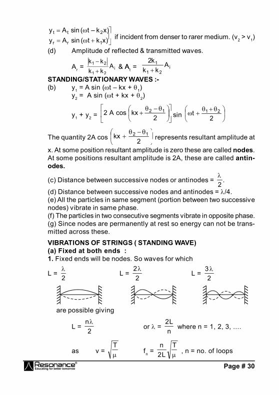
Page # 30
x)k t( sin A yx)k – t( sin A y
1rr
2tt if incident from denser to rarer medium. (v2 > v1)
(d) Amplitude of reflected & transmitted waves.
Ar = i21
21 Akkkk
& AAt = i
21
1 Akk
k2
STANDING/STATIONARY WAVES :-(b) y1 = A sin (t – kx + 1)
y2 = A sin (t + kx + 2)
y1 + y2 =
2kxcosA2 12
sin
2t 21
The quantity 2A cos
2kx 12 represents resultant amplitude at
x. At some position resultant amplitude is zero these are called nodes.At some positions resultant amplitude is 2A, these are called antin-odes.
(c) Distance between successive nodes or antinodes = 2
.
(d) Distance between successive nodes and antinodes = /4.(e) All the particles in same segment (portion between two successivenodes) vibrate in same phase.(f) The particles in two consecutive segments vibrate in opposite phase.(g) Since nodes are permanently at rest so energy can not be trans-mitted across these.
VIBRATIONS OF STRINGS ( STANDING WAVE)(a) Fixed at both ends :1. Fixed ends will be nodes. So waves for which
L = 2
L = 2
2L =
23
are possible giving
L = 2
nor =
nL2
where n = 1, 2, 3, ....
as v = T
fn = T
L2n
, n = no. of loops
Page # 31
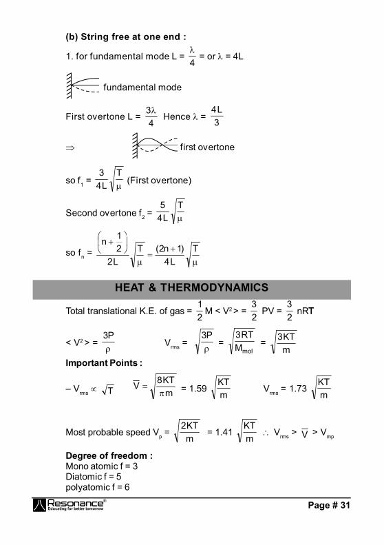
(b) String free at one end :
1. for fundamental mode L = 4
= or = 4L
fundamental mode
First overtone L = 4
3 Hence = 3
L4
first overtone
so f1 = T
L43
(First overtone)
Second overtone f2 = T
L45
so fn =
TL4
)1n2(TL221n
HEAT & THERMODYNAMICS
Total translational K.E. of gas = 21
M < V2 > = 23
PV = 23
nRTT
< V2 > = P3
Vrms = P3
= molMRT3
= mKT3
Important Points :
– Vrms T mKT8V
= 1.59 mKT
Vrms = 1.73 mKT
Most probable speed Vp = mKT2
= 1.41 mKT
Vrms > V > Vmp
Degree of freedom :Mono atomic f = 3Diatomic f = 5polyatomic f = 6
Page # 32
Maxwell’s law of equipartition of energy :Total K.E. of the molecule = 1/2 f KTFor an ideal gas :
Internal energy U = 2f
nRT
Workdone in isothermal process : W = [2.303 nRT log10 i
f
VV
]
Internal energy in isothermal process : U = 0
Work done in isochoric process : dW = 0Change in int. energy in isochoric process :
U = n 2f
R T = heat given
Isobaric process :Work done W = nR(Tf – Ti)change in int. energy U = nCv Theat given Q = U + W
Specific heat : Cv = 2f
R Cp =
1
2f
R
Molar heat capacity of ideal gas in terms of R :
(i) for monoatomic gas :v
p
CC
= 1.67
(ii) for diatomic gas :v
p
CC
= 1.4
(iii) for triatomic gas :v
p
CC
= 1.33
In general : = v
p
CC
=
f21
Mayer’s eq. Cp – Cv = R for ideal gas only
Adiabatic process :
Work done W = 1)TT(nR fi
Page # 33
In cyclic process :Q = WIn a mixture of non-reacting gases :
Mol. wt. = 21
2211
nnMnMn
Cv = 21
v2v1
nn
CnCn21
= )mix(v
)mix(p
CC
= ....CnCn
.....CnCn
21
21
v2v1
p2p1
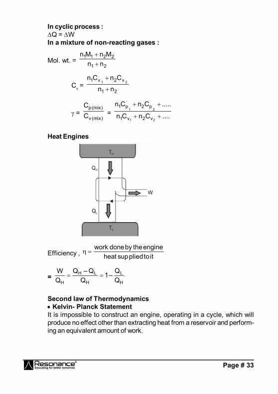
Heat Engines
Efficiency , ittopliedsupheatenginethebydonework
= H
L
H
LH
H QQ–1
QQ–Q
QW
Second law of Thermodynamics Kelvin- Planck StatementIt is impossible to construct an engine, operating in a cycle, which willproduce no effect other than extracting heat from a reservoir and perform-ing an equivalent amount of work.
Page # 34
Rudlope Classius StatementIt is impossible to make heat f low from a body at a lowertemperature to a body at a higher temperature without doing external workon the working substance
Entropy
change in entropy of the system is S = TQ
f
iif T
QS–S
In an adiabatic reversible process, entropy of the system remains con-stant.
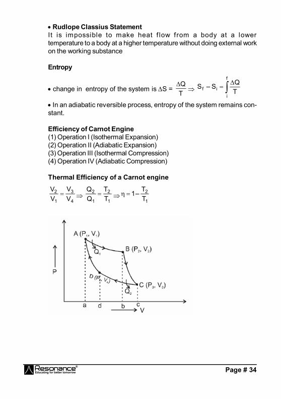
Efficiency of Carnot Engine(1) Operation I (Isothermal Expansion)(2) Operation II (Adiabatic Expansion)(3) Operation III (Isothermal Compression)(4) Operation IV (Adiabatic Compression)
Thermal Efficiency of a Carnot engine
4
3
1
2
VV
VV
1
2
1
2
TT
1
2
TT–1

Page # 35
Refrigerator (Heat Pump)
Refrigerator
Hot (T1) Hot (T2)Q1 Q2
W
Coefficient of performance, WQ2 =
1–TT
1
2
1 =
1–TT
1
2
1
Calorimetry and thermal expansionTypes of thermometers :
(a) Liquid Thermometer : T =
0100
0
× 100
(b) Gas Thermometer :
Constant volume : T =
0100
0
PPPP
× 100 ; P = P0 + g h
Constant Pressure : T =
VVV
T0
(c) Electrical Resistance Thermometer :
T =
0100
0t
RRRR
× 100
Thermal Expansion :(a) Linear :
= TLL
0
or L = L0 (1 + T)

Page # 36
(b) Area/superficial :
= TAA
0
or A = A0 (1 + T)
(c) volume/ cubical :
r = TVV
0
or V = V0 (1 + T)
32
Thermal stress of a material :
Y
AF
Energy stored per unit volume :
E = 21
K(L)2 or 2)L(L
AY21E
Variation of time period of pendulum clocks :
T = 21
T
T’ < T - clock-fast : time-gainT’ > T - clock slow : time-loss
CALORIMETRY :
Specific heat S = T.m
Q
Molar specific heat C = T.n
Q
Water equivalent = mWSW
HEAT TRANSFER
Thermal Conduction : dtdQ
= – KA dxdT
Thermal Resistance : R = KA
Page # 37
Series and parallel combination of rod :
(i) Series :eq
eq
K
= .......KK 2
2
1
1
(when A1 = A2 = A3 = .........)
(ii) Parallel : Keq Aeq = K1 A1 + K2 A2 + ...... (when 1 = 2 = 3 = .........)
for absorption, reflection and transmissionr + t + a = 1
Emissive power : E = tAU
Spectral emissive power : E = d
dE
Emissivity : e = temp. T atbody black a of Etemp. T atbody a of E
Kirchoff’s law : )body(a)body(E = E (black body)
Wein’s Displacement law : m . T = b.b = 0.282 cm-k
Stefan Boltzmann law :u = T4 s = 5.67 × 10⁻⁸ W/m2 k4
u = u – u0 = e A (T4 – T04)
Newton’s law of cooling : dtd
= k ( – 0) ; = 0 + (i – 0) e–k t
ELECTROSTATICSCoulomb force between two point charges
r|r|qq
41F 3
21
r0
=
r|r|
qq4
1221
r0
The electric field intensity at any point is the force experienced
by unit positive charge, given by 0q
FE
Electric force on a charge 'q' at the position of electric field
intensity E
produced by some source charges is EqF
Electric Potential
Page # 38
If (W P)ext is the work required in moving a point charge q from infinityto a point P, the electric potential of the point P is
0acc
extpp q
)W(V
Potential Difference between two points A and B isVA – VB
Formulae of E
and potential V
(i) Point charge E= r|r|
Kq2 = r
rKq
3
, V =
rKq
(ii) Infinitely long line charge rr2 0
=
rrK2
V = not defined, vB – vA = –2K ln (rB / rA)
(iii) Infinite nonconducting thin sheet n2 0
,
V = not defined, AB0
AB rr2
vv
(iv) Uniformly charged ring
Eaxis = 2/322 xR
KQx
, Ecentre = 0
Vaxis = 22 xR
KQ
, Vcentre =
RKQ
x is the distance from centre along axis.
(v) Infinitely large charged conducting sheet n0
V = not defined, AB0
AB rrvv
(vi) Uniformly charged hollow conducting/ nonconducting /solidconducting sphere
(a) for r|r|
kQE 2 , r R, V =
rKQ
(b) 0E for r < R, V =
RKQ
Page # 39
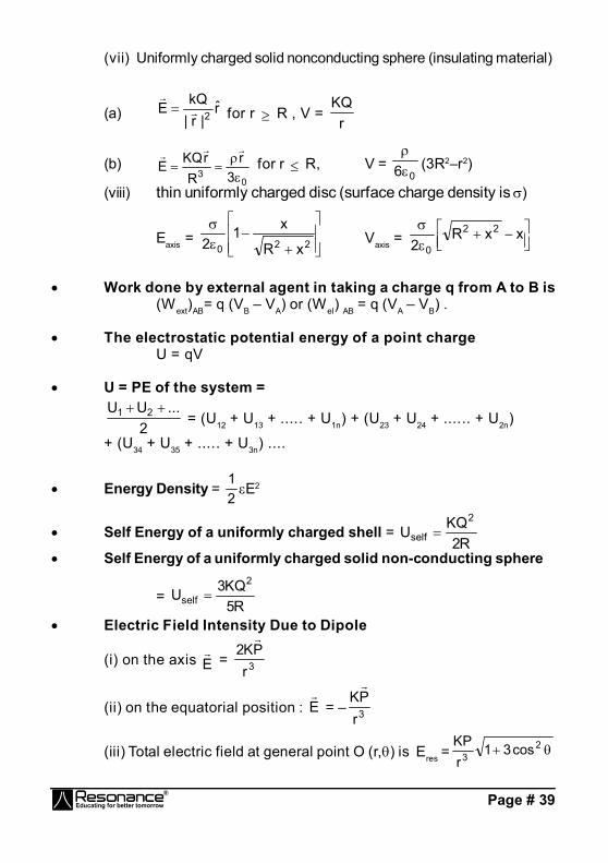
(vii) Uniformly charged solid nonconducting sphere (insulating material)
(a) r|r|
kQE 2 for r R , V =
rKQ
(b)0
3 3r
RrKQE
for r R, V = 06
(3R2–r2)
(viii) thin uniformly charged disc (surface charge density is )
Eaxis =
220 xR
x12 Vaxis =
xxR
222
0
Work done by external agent in taking a charge q from A to B is(Wext)AB= q (VB – VA) or (Wel) AB = q (VA – VB) .
The electrostatic potential energy of a point chargeU = qV
U = PE of the system =
2...UU 21
= (U12 + U13 + ..... + U1n) + (U23 + U24 + ...... + U2n)
+ (U34 + U35 + ..... + U3n) ....
Energy Density = 21E2
Self Energy of a uniformly charged shell = R2
KQU2
self
Self Energy of a uniformly charged solid non-conducting sphere
= R5
KQ3U2
self
Electric Field Intensity Due to Dipole
(i) on the axis E = 3r
PK2
(ii) on the equatorial position : E
= – 3rPK
(iii) Total electric field at general point O (r,) is Eres = 23 cos31
rKP

Page # 40
Potential Energy of an Electric Dipole in External Electric Field:
U = - p E.
Electric Dipole in Uniform Electric Field :
torque p x E ;
F = 0
Electric Dipole in Nonuniform Electric Field:
torque p x E ; U =
Ep , Net force |F| = r
Ep
Electric Potential Due to Dipole at General Point (r, ) :
V = P
r
p r
r
cos . 4 40
20
3
The electric flux over the whole area is given by
E = S dS.E
= S ndSE
Flux using Gauss's law, Flux through a closed surface
E = dSE
= 0
inq
.
Electric field intensity near the conducting surface
=0
n
Electric pressure : Electric pressure at the surface of a conductor isgiven by formula
P = 0
2
2
where is the local surface charge density..
Potential difference between points A and B
VB – VA = – B
A
rd.E
E
=
Vz
kVx
jVx
i = – Vz
kx
jx
i
= – V = –grad V
Page # 41
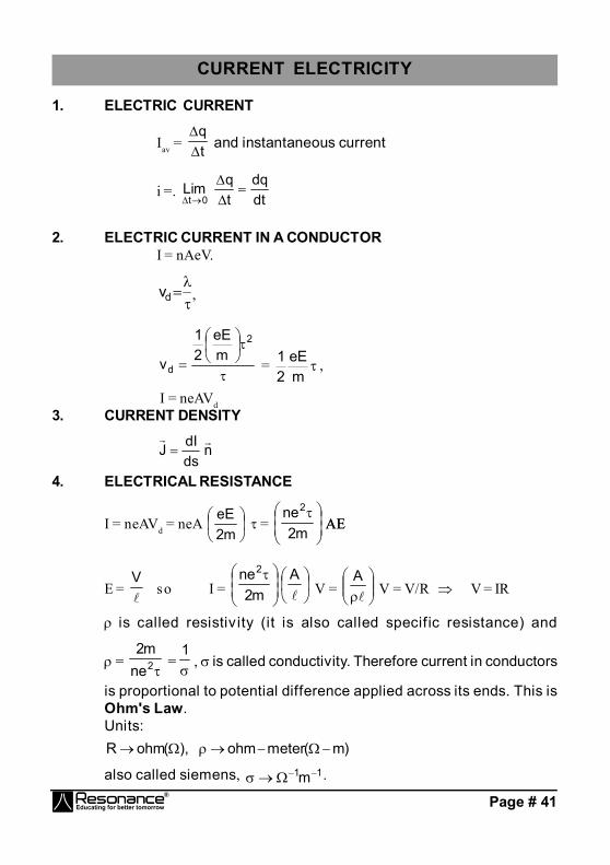
CURRENT ELECTRICITY
1. ELECTRIC CURRENT
Iav = tq
and instantaneous current
i =. dtdq
tqLim
0t
2. ELECTRIC CURRENT IN A CONDUCTORI = nAeV.
dv ,
2
dmeE
21
v = meE
21 ,
I = neAVd3. CURRENT DENSITY
ndsdIJ
4. ELECTRICAL RESISTANCE
I = neAVd = neA
m2eE
=
m2
ne2
AEAE
E =
Vso I =
Am2
ne2
V =
A
V = V/R V = IR
is called resistiv ity (it is also called specific resistance) and
= 2ne
m2 =1
, is called conductivity. Therefore current in conductors
is proportional to potential difference applied across its ends. This isOhm's Law.Units:
)m(meterohm),(ohmR
also called siemens, 11m .
Page # 42
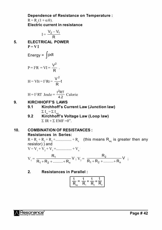
Dependence of Resistance on Temperature :R = Ro (1 + ).Electric current in resistance
I = R
VV 12
5. ELECTRICAL POWERP = V
Energy = pdt
P = I2R = V = RV2
.
H = Vt = 2 Rt = tRV 2
H = 2 RT Joule = 2.4
RT2 Calorie
9. KIRCHHOFF'S LAWS9.1 Kirchhoff’s Current Law (Junction law)
in = out9.2 Kirchhoff’s Voltage Law (Loop law)
IR + EMF =0”.
10. COMBINATION OF RESISTANCES :Resistances in Series:R = R1 + R2 + R3 +................ + Rn (this means Req is greater then anyresistor) ) andV = V1 + V2 + V3 +................ + Vn
.
V1 = VR.........RR
R
n21
1
; V2 = V
R.........RRR
n21
2
;
2. Resistances in Parallel :
Page # 43
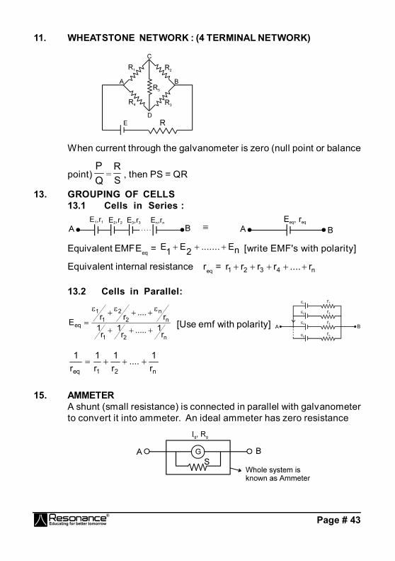
11. WHEATSTONE NETWORK : (4 TERMINAL NETWORK)
When current through the galvanometer is zero (null point or balance
point) QP
= SR
, then PS = QR
13. GROUPING OF CELLS13.1 Cells in Series :
Equivalent EMFEeq = E E ....... En1 2 [write EMF's with polarity]
Equivalent internal resistance req = n4321 r....rrrr
13.2 Cells in Parallel:
n21
nn
22
11
eq
r1.....r
1r
1r....rrE
[Use emf with polarity]
n21eq r1....
r1
r1
r1
15. AMMETERA shunt (small resistance) is connected in parallel with galvanometerto convert it into ammeter. An ideal ammeter has zero resistance

Page # 44
Ammeter is represented as follows -
If maximum value of current to be measured by ammeter is thenIG . RG = (I – IG)S
S = G
GG R.
S =
GG R
when >> G.
where = Maximum current that can be measured using the givenammeter.
16. VOLTMETERA high resistance is put in series with galvanometer. It is used tomeasure potential difference across a resistor in a circuit.
For maximum potential differenceV = G . RS + G RG
RS = G
V – RG If RG << RS RS
G
V
17. POTENTIOMETER
= Rr
VA – VB = rR
.R
Potential gradient (x) Potential difference per unit length of wire
x = L
VV BA =
rR
. LR

Page # 45
Application of potentiometer(a) To find emf of unknown cell and compare emf of two cells.
In case ,In figure (1) is joint to (2) then balance length = 11 = x1 ....(1)
in case ,In figure (3) is joint to (2) then balance length = 22 = x2 ....(2)
2
1
2
1
If any one of 1 or 2 is known the other can be found. If x is known thenboth 1 and 2 can be found
(b) To find current if resistance is knownVA – VC = x1IR1 = x1
= 1
1
Rx
Similarly, we can find the value of R2 also.Potentiometer is ideal voltmeter because it does not draw any currentfrom circuit, at the balance point.(c) To find the internal resistance of cell.
Ist arrangement 2nd arrangement

Page # 46
by first arrangement ’ = x1 ...(1)by second arrangement IR = x2
= R
x 2 , also = R'r'
R'r'
= R
x 2 R'r
x 1
= R
x 2
r’ = R 2
21
(d)Ammeter and voltmeter can be graduated by potentiometer.(e)Ammeter and voltmeter can be calibrated by potentiometer.
18. METRE BRIDGE (USE TO MEASURE UNKNOWN RESISTANCE)If AB = cm, then BC = (100 – ) cm.Resistance of the wire between A and B , R [ Specific resistance and cross-sectional area A are same for wholeof the wire ]
or R = ...(1)where is resistance per cm of wire.
If P is the resistance of wire between A and B thenP P = ()
Similarly, if Q is resistance of the wire between B and C, thenQ 100 –
Q = (100 – ) ....(2)
Dividing (1) by (2), QP
=
100
Page # 47
Applying the condition for balanced Wheatstone bridge, we get R Q = P X
x = R PQ
or X =
100 R
Since R and are known, therefore, the value of X can be calculated.
CAPACITANCE
1. (i) q V q = CVq : Charge on positive plate of the capacitorC : Capacitance of capacitor.V : Potential difference between positive and negative plates.
(ii) Representation of capacitor : , (
(iii) Energy stored in the capacitor : U =21
CV2 = C2
Q2
= 2QV
(iv) Energy density = 21
r E2 = 2
1
K E2
r = Relative permittivity of the medium.K= r : Dielectric Constant
For vacuum, energy density = 21E
2
(v) Types of Capacitors :(a) Parallel plate capacitor
C = dAr0
= K dA0
A : Area of platesd : distance between the plates( << size of plate )
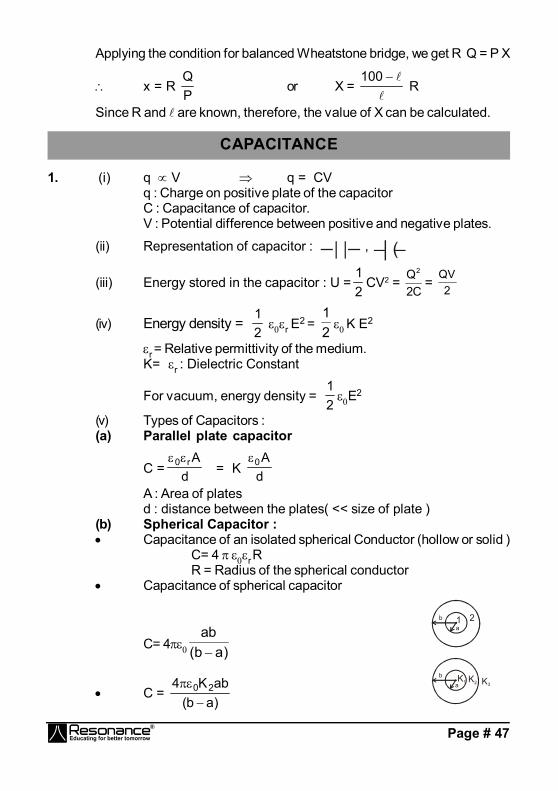
(b) Spherical Capacitor : Capacitance of an isolated spherical Conductor (hollow or solid )
C= 4 r RR = Radius of the spherical conductor
Capacitance of spherical capacitor
C= 4 )ab(ab
1 2ba
C = )ab(abK4 20
K1 K2 K3
ba
Page # 48
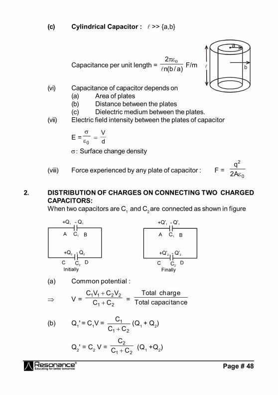
(c) Cylindrical Capacitor : >> {a,b}
Capacitance per unit length = )a/b(n2
F/m b
(vi) Capacitance of capacitor depends on(a) Area of plates(b) Distance between the plates(c) Dielectric medium between the plates.
(vii) Electric field intensity between the plates of capacitor
E =0
dV
Surface change density
(viii) Force experienced by any plate of capacitor : F = 0
2
A2q
2. DISTRIBUTION OF CHARGES ON CONNECTING TWO CHARGEDCAPACITORS:When two capacitors are C1 and C2 are connected as shown in figure
(a) Common potential :
V = 21
2211
CCVCVC
= cetancapaciTotaleargchTotal
(b) Q1' = C1V = 21
1
CCC
(Q1 + Q2)
Q2' = C2 V = 21
2
CCC (Q1 +Q2)
Page # 49
(c) Heat loss during redistribution :
H = Ui – Uf = 21
21
21
CCCC (V1 – V2)
2
The loss of energy is in the form of Joule heating in the wire.
3. Combination of capacitor :(i) Series Combination
321eq C1
C1
C1
C1
321
321 C1:
C1:
C1V:V:V
+Q
V1 V2V3
C2C1 C3
–Q +Q –Q +Q –Q
(ii) Parallel Combination :
Q+ –Q
C3
C2
C1
V
Q+ –Q
Q+ –Q
Ceq = C1 + C2 + C3 Q1: Q2 :Q3 = C1 : C2 : C3
4. Charging and Discharging of a capacitor :(i) Charging of Capacitor ( Capacitor initially uncharged ):
q = q0 ( 1 – e– t /)R
V C
q0 = Charge on the capacitor at steady stateq0 = CV
Page # 50
Time constant = CReq.
I = 0q
e – t / RV
e– t /
(ii) Discharging of Capacitor :q = q0 e – t /
q0 = Initial charge on the capacitor
I = 0q
e – t /
R
C
q0
0.37v0
t
q
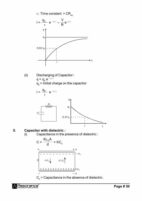
5. Capacitor with dielectric :(i) Capacitance in the presence of dielectric :
C = dAK 0 = KC0
+ + + + + + + + + + + + + +
0
+ +
– –
V
b+
– b– – – – – – – – – – –
0b
C0 = Capacitance in the absence of dielectric.
Page # 51
(ii) Ein = E – Eind = 0
– 0
b
= 0K
= d
V
E : 0
Electric field in the absence of dielectric
Eind : Induced (bound) charge density.
(iii) b = (1 – K1
).
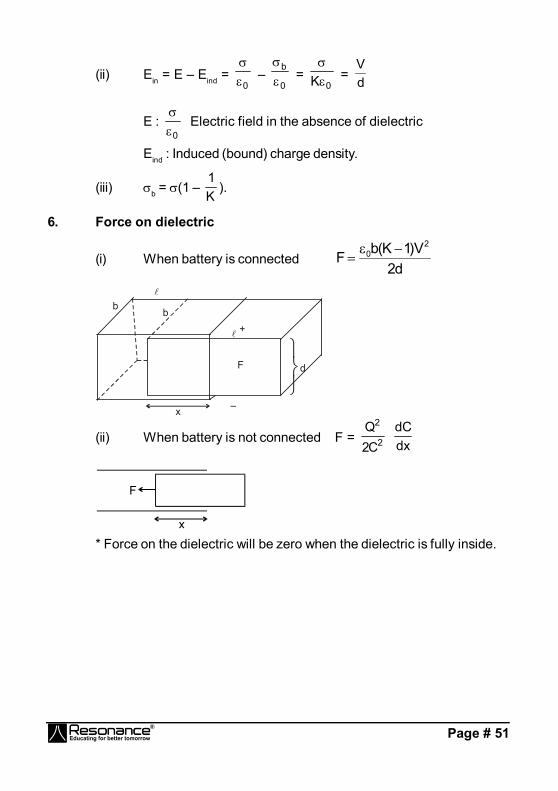
6. Force on dielectric
(i) When battery is connectedd2
V)1K(bF2
0
+
–
b b
d
F
x
(ii) When battery is not connected F = 2
2
C2Q
dxdC
* Force on the dielectric will be zero when the dielectric is fully inside.
Page # 52
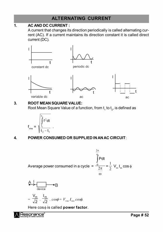
ALTERNATING CURRENT1. AC AND DC CURRENT :
A current that changes its direction periodically is called alternating cur-rent (AC). If a current maintains its direction constant it is called directcurrent (DC).
3. ROOT MEAN SQUARE VALUE:Root Mean Square Value of a function, from t1 to t2, is defined as
frms = 12
22
1
tt
dtft
t
.
4. POWER CONSUMED OR SUPPLIED IN AN AC CIRCUIT:
Average power consumed in a cycle =
2
2
o
Pdt
=21
Vm m cos
= 2Vm
. 2m
. cos = Vrms rms cos .
Here cos is called power factor.

Page # 53
5. SOME DEFINITIONS:The factor cos is called Power factor.m sin is called wattless current.
Impedance Z is defined as Z = m
mV
= rms
rmsV
L is called inductive reactance and is denoted by XL.
C1
is called capacitive reactance and is denoted by XC.
6. PURELY RESISTIVE CIRCUIT:
I =R
sv=
RtsinVm
= m sin t
m = RVm
rms = R
Vrms
<P> = Vrmsrmscos R
Vrms2
7. PURELY CAPACITIVE CIRCUIT:
I = =C
1Vm
cos t
= C
m
XV
cos t = m cos t.
XC = C1
and is called capacitive reactance.
V
t
v
T
t
Ii

Page # 54
IC leads by vC by /2 Diagrammatically(phasor diagram) it is represented as
m
Vm
.
Since º, <P> = Vrms rmscos
MAGNETIC EFFECT OF CURRENT & MAGNETIC FORCE ONCHARGE/CURRENT
1. Magnetic field due to a moving point charge
30
r)rv(q
4B
2. Biot-savart's Lawv r
30
rrd
4I
dB
3. Magnetic field due to a straight wire1
2
Pr
B =
4
0 rI
(sin 1 + sin 2)
4. Magnetic field due to infinite straight wirePr
B = 2
0 rI
5. Magnetic field due to circular loop
(i) At centre B = r2NI0
(ii) At Axis B =
2/322
20
)xR(RN
2
Page # 55
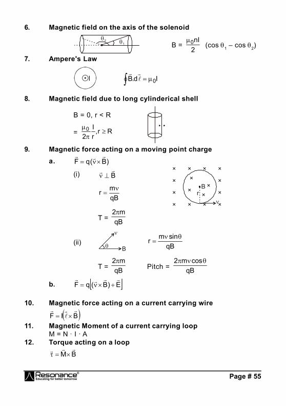
6. Magnetic field on the axis of the solenoid2 1 B =
2nI0 (cos 1 – cos 2)
7. Ampere's Law
Id.B 0
8. Magnetic field due to long cylinderical shell
B = 0, r < R
= Rr,rI
20
9. Magnetic force acting on a moving point chargea. )B(qF
(i) B
qBmr
× × × ×
×
×
×
×
×
×
×××
×
×
×
Br
T = qBm2
(ii)
B qBsinmr
T = qBm2
Pitch = qBcosm2
b. E)B(qF
10. Magnetic force acting on a current carrying wire
BIF
11. Magnetic Moment of a current carrying loopM = N · I · A
12. Torque acting on a loopBM
Page # 56
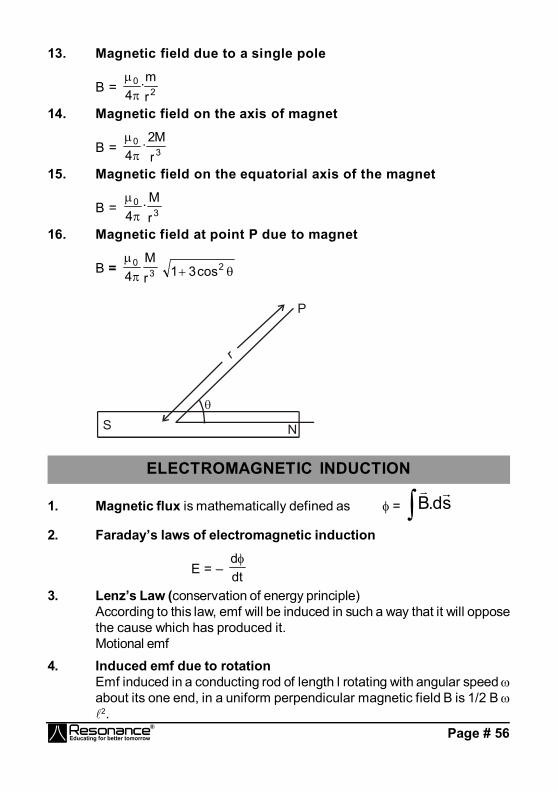
13. Magnetic field due to a single pole
B = 20
rm·
4
14. Magnetic field on the axis of magnet
B = 30
rM2·
4
15. Magnetic field on the equatorial axis of the magnet
B = 30
rM·
4
16. Magnetic field at point P due to magnet
B = 30
rM
4
2cos31
S
P
r
N
ELECTROMAGNETIC INDUCTION
1. Magnetic flux is mathematically defined as = sd.B
2. Faraday’s laws of electromagnetic induction
E = – dtd
3. Lenz’s Law (conservation of energy principle)According to this law, emf will be induced in such a way that it will opposethe cause which has produced it.Motional emf
4. Induced emf due to rotationEmf induced in a conducting rod of length l rotating with angular speed about its one end, in a uniform perpendicular magnetic field B is 1/2 B 2.
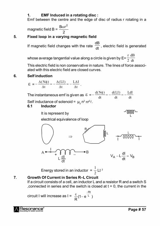
Page # 57
1. EMF Induced in a rotating disc :Emf between the centre and the edge of disc of radius r rotating in a
magnetic field B = 2rB 2
5. Fixed loop in a varying magnetic field
If magnetic field changes with the rate dtdB
, electric field is generated
whose average tangential value along a circle is given by E= dtdB
2r
This electric field is non conservative in nature. The lines of force associ-ated with this electric field are closed curves.
6. Self induction
= tIL
t)LI(
t)N(
.
The instantaneous emf is given as = dtLdI
dt)LI(d
dt)N(d
Self inductance of solenoid = µ0 n2 r2.
6.1 Inductor
It is represent byelectrical equivalence of loop
BA VdtdILV
Energy stored in an inductor = 21
L 2
7. Growth Of Current in Series R–L CircuitIf a circuit consists of a cell, an inductor L and a resistor R and a switch S,connected in series and the switch is closed at t = 0, the current in the
circuit I will increase as I = )e1(R
LRt
Page # 58
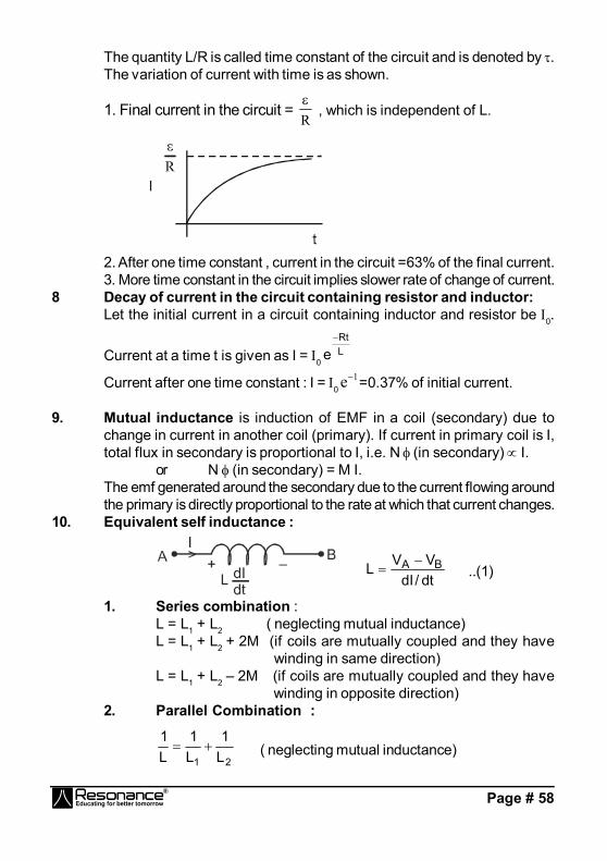
The quantity L/R is called time constant of the circuit and is denoted by .The variation of current with time is as shown.
1. Final current in the circuit = R
, which is independent of L.
2. After one time constant , current in the circuit =63% of the final current.3. More time constant in the circuit implies slower rate of change of current.
8 Decay of current in the circuit containing resistor and inductor:Let the initial current in a circuit containing inductor and resistor be 0.
Current at a time t is given as I = 0LRt
e
Current after one time constant : I = 01e =0.37% of initial current.
9. Mutual inductance is induction of EMF in a coil (secondary) due tochange in current in another coil (primary). If current in primary coil is I,total flux in secondary is proportional to I, i.e. N (in secondary) I.
or N (in secondary) = M I.The emf generated around the secondary due to the current flowing aroundthe primary is directly proportional to the rate at which that current changes.
10. Equivalent self inductance :
dt/dIVVL BA
..(1)
1. Series combination :L = L1 + L2 ( neglecting mutual inductance)L = L1 + L2 + 2M (if coils are mutually coupled and they have
winding in same direction)L = L1 + L2 – 2M (if coils are mutually coupled and they have
winding in opposite direction)2. Parallel Combination :
21 L1
L1
L1
( neglecting mutual inductance)

Page # 59
For two coils which are mutually coupled it has been found that M 21LL
or M =k 21LL where k is called coupling constant and its value is lessthan or equal to 1.
Primary coil
S
EPES
Secondary coil
Magnetic Core
s
p
p
s
p
s
NN
EE
, where denota-
tions have their usual mean-ings.
NS > NP ES > EP for step up transformer.
12. LC Oscillations
LC12
GEOMETRICAL OPTICS
1. Reflection of Light(b) i = r1.3 Characteristics of image due to Reflection by a PlaneMirror:(a) Distance of object from mirror = Distance of image from the mirror.(b) The line joining a point object and its image is normal to the reflectingsurface.(c) The size of the image is the same as that of the object.(d) For a real object the image is virtual and for a virtual object the imageis real
2. Relation between velocity of object and image :From mirror property : xim = - xom , yim = yom and zim = zomHere xim means ‘x’ coordinate of image with respect to mirror.Similarly others have meaning.

Page # 60
Differentiating w.r.t time , we getv(im)x = -v(om)x ; v(im)y = v(om)y ; v(im)z = v(om)z ,
3. Spherical Mirror
1v +
1u =
2R =
1f ..... Mirror formula
x co–ordinate of centre of Curvature and focus of Concavemirror are negative and those for Convex mirror are positive.In case of mirrors since light rays reflect back in - X direction,therefore -ve sign of v indicates real image and +vesign of v indicates virtual image
(b) Lateral magnification (or transverse magnification)
m= h
h2
1
m = v
u.
(d) On differentiating (a) we getdvdu =
v
u
2
2 .
(e) On dif ferentiating (a) with respect to time we get
dvdt
vu
dudt
2
2 ,where dvdt is the velocity of image along Principal
axis anddudt is the velocity of object along Principal axis. Negative
sign implies that the image , in case of mirror, always movesin the direction opposite to that of object.This discussion isfor velocity with respect to mirror and along the x axis.
(f) Newton's Formula: XY = f 2X and Y are the distances ( along the principal axis ) of the objectand image respectively from the principal focus. This formula canbe used when the distances are mentioned or asked from thefocus.
(g) Optical power of a mirror (in Diopters) = f1
f = focal length with sign and in meters.(h) If object lying along the principal axis is not of very small size, the
longitudinal magnification =12
12
uuvv
(it will always be inverted)

Page # 61
4. Refraction of Light
vacuum. speed of light in vacuumspeed of light in medium
cv
.
4.1 Laws of Refraction (at any Refracting Surface)
(b)rSin
iSin = Constant for any pair of media and for light of a given
wave length. This is known as Snell's Law. More precisely,
Sin i
Sin r =
n
n2
1
= v
v1
2
=
1
2
4.2 Deviation of a Ray Due to RefractionDeviation () of ray incident at i and refracted at r is given by = |i r|.
5. Principle of Reversibility of Light RaysA ray travelling along the path of the reflected ray is reflected along thepath of the incident ray. A refracted ray reversed to travel back along itspath will get refracted along the path of the incident ray. Thus the incidentand refracted rays are mutually reversible.
7. Apparent Depth and shift of Submerged ObjectAt near normal incidence (small angle of incidence i) apparent depth (d)is given by:
d=relativen
d nrelative = )refractionofmediumof.I.R(n)incidenceofmediumof.I.R(n
r
i
Apparent shift = d
reln11
Refraction through a Composite Slab (or Refraction through anumber of parallel media, as seen from a medium of R. I. n0)Apparent depth (distance of final image from final surface)
= t
n rel
1
1 +
t
n rel
2
2 +
t
n rel
3
3
+......... + reln
n
nt
Page # 62
Apparent shift = t1
rel1n11 + t2
rel2n11 +........+
relnnn1
8. Critical Angle and Total Internal Reflection ( T. I. R.)
C = sin 1 nn
r
d
(i) Conditions of T. I. R.(a) light is incident on the interface from denser medium.(b) Angle of incidence should be greater than the critical
angle (i > c).9. Refraction Through Prism
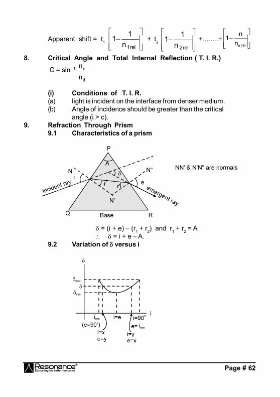
9.1 Characteristics of a prism
= (i + e) (r1 + r2) and r1 + r2 = A = i + e A.
9.2 Variation of versus i
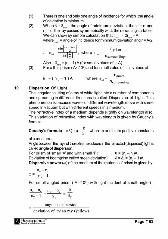
Page # 63
(1) There is one and only one angle of incidence for which the angleof deviation is minimum.
(2) When = min , the angle of minimum deviation, then i = e andr1 = r2, the ray passes symmetrically w.r.t. the refracting surfaces.We can show by simple calculation that min = 2imin – Awhere imin = angle of incidence for minimum deviation and r = A/2.
nrel = 2A2
A
sinsin m
, where nrel = n
nprism
surroundings
Alsomin = (n 1) A (for small values of A)(3) For a thin prism ( A 10o) and for small value of i, all values of
= ( nrel 1 ) A where nrel = gsurroundin
prism
nn
10. Dispersion Of LightThe angular splitting of a ray of white light into a number of componentsand spreading in different directions is called Dispersion of Light. Thisphenomenon is because waves of different wavelength move with samespeed in vacuum but with different speeds in a medium.The refractive index of a medium depends slightly on wavelength also.This variation of refractive index with wavelength is given by Cauchy’sformula.
Cauchy's formula n () =ab
2 where a and b are positive constants
of a medium.Angle between the rays of the extreme colours in the refracted (dispersed) light iscalled angle of dispersion.For prism of small ‘A’ and with small ‘i’ : = (nv – nr)ADeviation of beam(also called mean deviation) = y = (ny – 1)ADispersive power () of the medium of the material of prism is given by:
= 1nnn
y
rv
For small angled prism ( A 10o ) with light incident at small angle i :
1nnn
y
rv
=y
rv
= y
= angular dispersion
deviation of mean ray yellow( )

Page # 64
[ ny = 2
nn rv if ny is not given in the problem ]
= y
rv
= 1nnn
y
rv
[take ny = 2nn rv if value of ny is not given in
the problem]nv, nr and ny are R. I. of material for violet, red and yellow colours respectively.
11. Combination of Two PrismsTwo or more prisms can be combined in various ways to get differentcombination of angular dispersion and deviation.(a) Direct Vision Combination (dispersion without deviation)
The condition for direct vision combination is :
1
2nn rv
A
1
2nn rv A 1ny A = = 1ny AA
(b) Achromatic Combination (deviation without dispersion.)Condition for achromatic combination is: (nv
nr) A = (nv nr) A
12. Refraction at Spherical SurfacesFor paraxial rays incident on a spherical surface separating two media:
vn2
un1 =
Rnn 12
where light moves from the medium of refractive index n1 to the mediumof refractive index n2.
Transverse magnification (m) (of dimension perpendicular to principal axis)
due to refraction at spherical surface is given by m = RuRv
=
1
2
n/un/v
13. Refraction at Spherical Thin LensA thin lens is called convex if it is thicker at the middle and it iscalled concave if it is thicker at the ends.For a spherical, thin lens having the same medium on both sides:
1
v
1
u = (nrel 1)
1 1
1 2R R
where nrel =
n
nlens
medium

Page # 65
1f = (nrel 1)
1 1
1 2R R
1
v
1
u =
1f Lens Maker's Formula
m = v
u
Combination Of Lenses:1 1 1 1
1 2 3F f f f ...
OPTICAL INSTRUMENT
SIMPLE MICROSCOPE
Magnifying power : 0U
D
when image is formed at infinity fDM
When change is formed at near print D. fD1MD
COMPOUND MICROSCOPEMagnifying power Length of Microscope
e0
00
UUDV
M L = V0 + Ue
e0
0
fUDV
M L = V0 + fe
e0
0D f
D1UV
M LD =e
e0 fD
f.DV
Page # 66
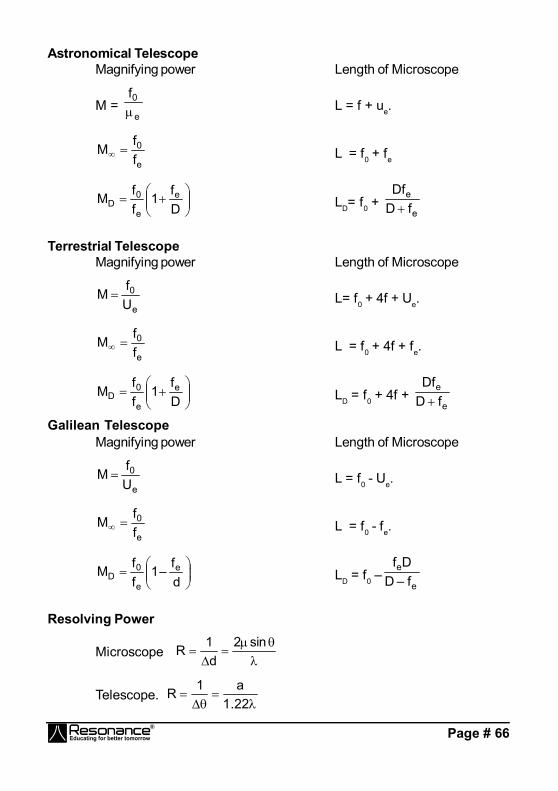
Astronomical TelescopeMagnifying power Length of Microscope
M = e
0f L = f + ue.
e
0
ff
M L = f0 + fe
Df1
ffM e
e
0D LD= f0 +
e
e
fDDf
Terrestrial TelescopeMagnifying power Length of Microscope
e
0
Uf
M L= f0 + 4f + Ue.
e
0
ff
M L = f0 + 4f + fe.
Df
1ff
M e
e
0D LD = f0 + 4f +
e
e
fDDf
Galilean TelescopeMagnifying power Length of Microscope
e
0
Uf
M L = f0 - Ue.
e
0
ff
M L = f0 - fe.
df–1
ffM e
e
0D LD = f0 – e
e
f–DDf
Resolving Power
Microscope
sin2d
1R
Telescope.
22.1a1R
Page # 67
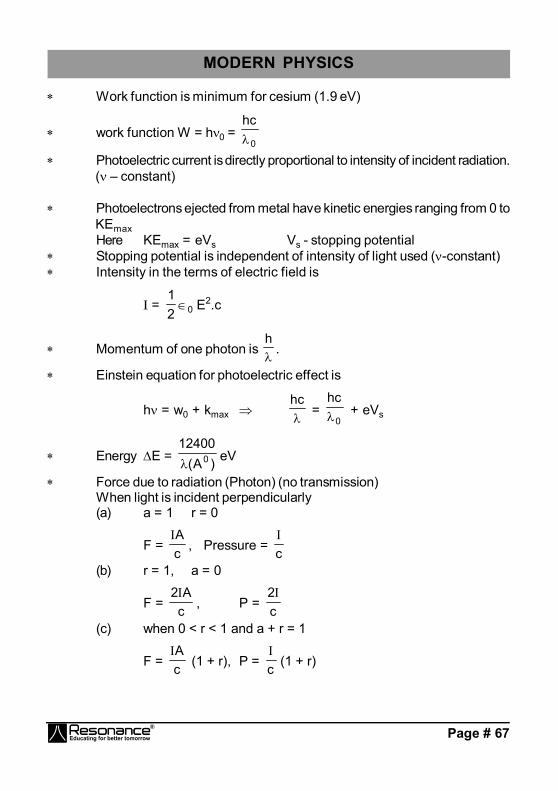
MODERN PHYSICS
Work function is minimum for cesium (1.9 eV)
work function W = h0 = 0
hc
Photoelectric current is directly proportional to intensity of incident radiation.( – constant)
Photoelectrons ejected from metal have kinetic energies ranging from 0 toKEmaxHere KEmax = eVs Vs - stopping potential
Stopping potential is independent of intensity of light used (-constant) Intensity in the terms of electric field is
I = 210 E
2.c
Momentum of one photon is h
.
Einstein equation for photoelectric effect is
h = w0 + kmax hc
= 0
hc + eVs
Energy E = )A(12400
0 eV
Force due to radiation (Photon) (no transmission)When light is incident perpendicularly(a) a = 1 r = 0
F = cA
, Pressure = c
(b) r = 1, a = 0
F = cA2
, P = c2
(c) when 0 < r < 1 and a + r = 1
F = cA
(1 + r), P = c
(1 + r)
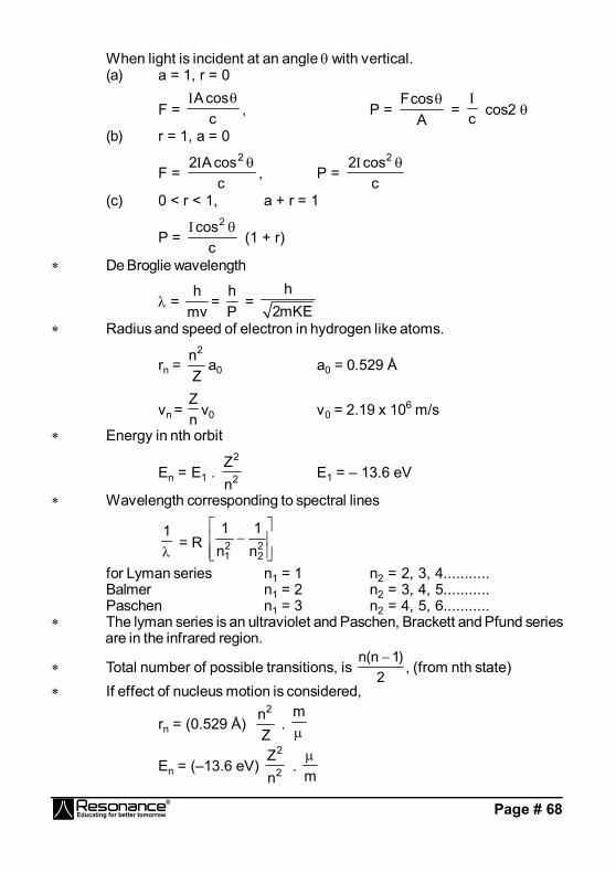
Page # 68
When light is incident at an angle with vertical.(a) a = 1, r = 0
F = ccosA
, P = A
cosF = c
cos2
(b) r = 1, a = 0
F = ccosA2 2
, P = c
cos2 2
(c) 0 < r < 1, a + r = 1
P = c
cos2 (1 + r)
De Broglie wavelength
= mvh
= Ph
= h
2mKE Radius and speed of electron in hydrogen like atoms.
rn = Zn2
a0 a0 = 0.529 Å
vn = nZ
v0 v0 = 2.19 x 10⁶ m/s
Energy in nth orbit
En = E1 . 2
2
nZ
E1 = – 13.6 eV
Wavelength corresponding to spectral lines
1
= R
2
221 n
1n1
for Lyman series n1 = 1 n2 = 2, 3, 4...........Balmer n1 = 2 n2 = 3, 4, 5...........Paschen n1 = 3 n2 = 4, 5, 6...........
The lyman series is an ultraviolet and Paschen, Brackett and Pfund seriesare in the infrared region.
Total number of possible transitions, is 2
)1n(n , (from nth state)
If effect of nucleus motion is considered,
rn = (0.529 Å) Zn2
. m
En = (–13.6 eV) 2
2
nZ
. m
Page # 69
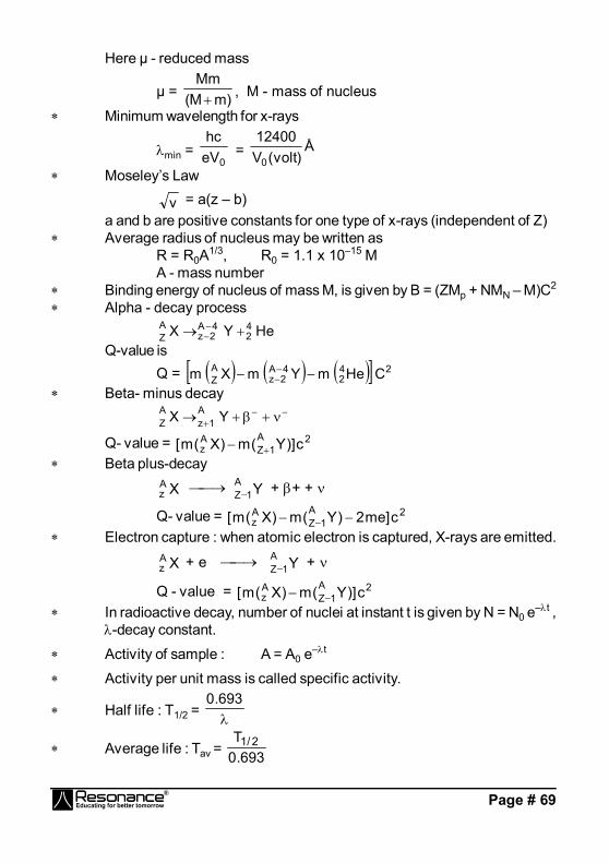
Here µ - reduced mass
µ = )mM(Mm , M - mass of nucleus
Minimum wavelength for x-rays
min = 0eV
hc = Å
)volt(V12400
0 Moseley’s Law
v = a(z – b)a and b are positive constants for one type of x-rays (independent of Z)
Average radius of nucleus may be written asR = R0A
1/3, R0 = 1.1 x 10⁻¹⁵ MA - mass number
Binding energy of nucleus of mass M, is given by B = (ZMp + NMN – M)C2
Alpha - decay processHeYX 4
24A2z
AZ
Q-value isQ = 24
24A2z
AZ CHemYmXm
Beta- minus decay
YX A1z
AZ
Q- value = 2A1Z
Az c)]Y(m)X(m[
Beta plus-decay
XAz YA
1Z + + +
Q- value = 2A1Z
Az c]me2)Y(m)X(m[
Electron capture : when atomic electron is captured, X-rays are emitted.
XAz + e YA
1Z +
Q - value = 2A1Z
Az c)]Y(m)X(m[
In radioactive decay, number of nuclei at instant t is given by N = N0 e–t ,
-decay constant.
Activity of sample : A = A0 e–t
Activity per unit mass is called specific activity.
Half life : T1/2 = 693.0
Average life : Tav = 693.0T 2/1
Page # 70
A radioactive nucleus can decay by two different processes having halflives t1 and t2 respectively. Effective half-life of nucleus is given by
21 t1
t1
t1
.
WAVE OPTICSInterference of waves of intensity 1 and 2 :resultant intensity, = 1 + 2 + 212 cos () where, = phasedifference.
For Constructive Interference : max = 221
For Destructive interference : min = 221 If sources are incoherent = 1 + 2 , at each point.YDSE :Path difference, p = S2P – S1P = d sin
if d < < D = Ddy
if y << Dfor maxima,p = n y = n n = 0, ±1, ±2 .......for minima
p = p =
3........- 2,- -1,n 2
)1n2(
....3......... 2, 1, n 2
)1n2(
y =
3.......- 2,- -1,n 2
)1n2(
....3......... 2, 1, n 2
)1n2(
where, fringe width = dD
Here, = wavelength in medium.
Highest order maxima : nmax =
d
total number of maxima = 2nmax + 1
Highest order minima : nmax =
2
1d
total number of minima = 2nmax.

Page # 71
Intensity on screen : = 1 + 2 + 212 cos () where, = p2
If 1 = 2, = 41 cos2
2YDSE with two wavelengths 1 & 2 :The nearest point to central maxima where the bright fringes coincide:
y = n11 = n22 = Lcm of 1 and 2
The nearest point to central maxima where the two dark fringescoincide,
y = (n1 – 21
) 1 = n2 – 21
) 2
Optical path differencepopt = p
= 2
p = vacuum
2
popt.
= ( – 1) t. dD
= ( – 1)t B
.
YDSE WITH OBLIQUE INCIDENCEIn YDSE, ray is incident on the slit at an inclination of 0 tothe axis of symmetry of the experimental set-up
1
P1
P2
B0O'
S2dsin0
S1
O02
We obtain central maxima at a point where, p = 0.or 2 = 0.
This corresponds to the point O’ in the diagram.Hence we have path difference.
p =
O'below points for)sind(sinO'&O between points for)sin(sind
O above points for)sin(sind
0
0
0
... (8.1)

Page # 72
THIN-FILM INTERFERENCEfor interference in reflected light 2d
=
ceinterferen veconstructifor)21n(
ceinterferen edestructivforn
for interference in transmitted light 2d
=
ceinterferen edestructivfor)21n(
ceinterferen veconstructiforn
Polarisation
= tan .(brewster's angle) + r = 90°(reflected and refracted rays are mutuallyperpendicular.)
Law of Malus.I = I0 cos2
I = KA2 cos2
Optical activity
CLCt
= rotation in length L at concentration C.
Diffraction a sin = (2m + 1) /2 for maxima. where m = 1, 2, 3 ......
sin = a
m, m = 1, 2, 3......... for minima.
Linear width of central maxima = ad2
Angular width of central maxima = a2
Page # 73
2
0 2/2/sin
where =
sina
Resolving power .
R =
12 –
where , 2
21 , = 2 - 1
GRAVITATIONGRAVITATION : Universal Law of Gravitation
F 221
rmm
or F = 221
rmmG
where G = 6.67 × 10⁻¹¹ Nm2 kg–2 is the universal gravitational constant.
Newton's Law of Gravitation in vector form :
12F
= 221
rmGm
12r & 12F
= 221
rmGm
Now 2112 rr , Thus 12221
21 rr
mmGF
.
Comparing above, we get 2112 FF
Gravitational Field E = mF
= 2rGM
Gravitational potential : gravitational potential,
V = – r
GM. E = –
drdV
.
1. Ring. V = 2/122 )ra(orxGM
& E = r
)ra(rGM
2/322
or E = – 2xcosGM

Page # 74
Gravitational field is maximum at a distance,
r = ± 2a and it is – 2a33GM22. Thin Circular Disc.
V =
rra
aGM2
21
222 & E = –
21
222
ar
r1aGM2
= – cos1aGM2
2
3. Non conducting solid sphere(a) Point P inside the sphere. r < a, then
V = )ra3(a2
GM 223 & E = – 3a
rGM, and at the centre V = –
a2GM3
and E = 0
(b) Point P outside the sphere .
r > a, then V = r
GM & E = – 2r
GM
4. Uniform Thin Spherical Shell / Conducting solid sphere(a) Point P Inside the shell.
r < a , then V = aGM
& E = 0
(b) Point P outside shell.
r > a, then V = rGM
& E = – 2rGM
VARIATION OF ACCELERATION DUE TO GRAVITY :1. Effect of Altitude
gh = 2e
e
hRGM = g
2
eRh1
~ g
eRh21 when h << R.
2. Effect of depth gd = g
eRd1
3. Effect of the surface of EarthThe equatorial radius is about 21 km longer than its polar radius.
We know, g = 2e
e
RGM
Hence gpole > gequator.
SATELLITE VELOCITY (OR ORBITAL VELOCITY)
v0 = 21
e
e
hRGM
= 21
e
2e
hRRg
Page # 75
When h << Re then v0 = eRg
v0 = 6104.68.9 = 7.92 × 10³ ms–1 = 7.92 km s1
Time period of Satellite
T =
21
e
2e
e
hRRg
hR2
=
21
3e
e ghR
R2
Energy of a Satellite
U = r
mGMe K.E. =
r2mGMe ; then total energy E = –
e
eR2
mGM
Kepler's LawsLaw of area :The line joining the sun and a planet sweeps out equal areas in equalintervals of time.
Areal velocity = time
sweptarea= dt
)rd(r21
=7
21
r2 dtd
= constant .
Hence 21
r2 = constant. Law of periods : 3
2
RT
= constant
FLUID MECHANICS & PROPERTIES OF MATTERFLUIDS, SURFACE TENSION, VISCOSITY & ELASTICITY :
1. Hydraulic press. p = faAFor
AF
af
.
Hydrostatic Paradox PA = PB = PC(i) Liquid placed in elevator : When elevator accelerates upward withacceleration a0 then pressure in the fluid, at depth ‘h’ may be given by,
p = h [g + a0]
and force of buoyancy, B = m (g + a0)
(ii) Free surface of liquid in horizontal acceleration :
tan = ga0
Page # 76
p1 – p2 = a0 where p1 and p2 are pressures at points 1 & 2.
Then h1 – h2 = ga0
(iii) Free surface of liquid in case of rotating cylinder.
h = g2v2
= g2r22
Equation of Continuity
a1v1 = a2v2
In general av = constant .
Bernoulli’s Theorem
i.e. P
+ 21
v2 + gh = constant.
(vi) Torricelli’s theorem – (speed of efflux) v=2
1
22
AA1
gh2
,A2 = area of hole
A1 = area of vessel.
ELASTICITY & VISCOSITY : stress = AF
bodytheofareaforcerestoring
Strain, = ionconfiguratoriginalionconfiguratinchange
(i) Longitudinal strain = LL
(ii) v = volume strain = VV
(iii) Shear Strain : tan or =
x
1. Young's modulus of elasticity Y = LA
FLL/L
A/F
Potential Energy per unit volume = 21
(stress × strain) = 21
(Y × strain2 )
Inter-Atomic Force-Constant k = Yr0.
Page # 77
Newton’s Law of viscosity, F A dxdv
or F = – A dxdv
Stoke’s Law F = 6 r v. Terminal velocity = 92
g)(r2
SURFACE TENSION
Surface tension(T) = )(linetheofLength)F(lineimaginarytheofeitheronforceTotal
;
T = S = AW
Thus, surface tension is numerically equal to surface energy or workdone per unit increase surface area.
Inside a bubble : (p – pa) = rT4
= pexcess ;
Inside the drop : (p – pa) = rT2
= pexcess
Inside air bubble in a liquid :(p – pa) = rT2
= pexcess
Capillary Rise h =gr
cosT2
SOUND WAVES(i) Longitudinal displacement of sound wave
= A sin (t – kx)(ii) Pressure excess during travelling sound wave
Pex = xB
(it is true for travelling
= (BAk) cos(t – kx)wave as well as standing waves)Amplitude of pressure excess = BAk
(iii) Speed of sound C = E
Where E = Ellastic modulus for the medium = density of medium
– for solid C = Y

Page # 78
where Y = young's modulus for the solid
– for liquid C = B
where B = Bulk modulus for the liquid
– for gases C = 0M
RTPB
where M0 is molecular wt. of the gas in (kg/mole)Intensity of sound wave :
<> = 22f2A2v = v2P2
m
< > Pm
2
(iv) Loudness of sound : L =
010log10 dB
where I0 = 10–12 W/m2 (This the minimum intensity human ears canlisten)
Intensity at a distance r from a point source = 2r4P
Interference of Sound Waveif P1 = pm1 sin (t – kx1 + 1)
P2 = pm2 sin (t – kx2 + 2)resultant excess pressure at point O is
p = P1 + P2
p = p0 sin (t – kx + )
p0 = cospp2pp2121 mm
2m
2m
where = [k (x2 – x1) + (1 – 2)]
and I = I1 + I2 + 212 (i) For constructive interference
= 2n and p0 = pm1 + pm2 (constructive interference)(ii) For destructive interfrence
= (2n+ 1) and p0 = | pm1 – pm2 | (destructive interference)
If is due to path difference only then = 2x.
Condition for constructive interference : x = n
Condition for destructive interference : x = (2n + 1)2
Page # 79
(a) If pm1 = pm2 and resultant p = 0 i.e. no sound
(b) If pm1 = pm2 and = 0 , 2, 4, ...p0 = 2pm & I0 = 4I1p0 = 2pm1
Close organ pipe :
f = 4
v)1n2(.,.........4v5,
4v3,
4v
n = overtone
Open organ pipe :
f = 2
nV.,.........2v3,
2v2,
2v
Beats : Beatsfrequency = |f1 – f2|.Doppler’s Effect
The observed frequency, f = f
s
0
vvvv
and Apparent wavelength =
vvv s
ELECTRO MAGNETIC WAVESMaxwell's equations
0/QdAE (Gauss's Law for electricity)
0dAB (Gauss's Law for magnetism)
dtd–
dE B (Faraday's Law)
dtd
idB E00c0
(Ampere-Maxwell Law)
Oscillating electric and magnetic fieldsE= Ex(t) = E0 sin (kz - t)
= E0 sin
vt–z2 = E0 sin
Tt–z2
E0/B0 = c
c = 00/1 c is speed of light in vaccum
/1v v is speed of light in medium

Page # 80
cUp energy transferred to a surface in time t is U, the magnitude of
the total momentum delivered to this surface (for completeabsorption) is pElectromagnetic spectrum
Type Wavelength range
Production Detection
Radio > 0.1m Rapid acceleration and decelerations of electrons in aerials
Receiver's aerials
Microwave 0.1m to 1mm Klystron value or magnetron value
Point contact diodes
Infra-red 1mm to 700nm Vibration of atoms and molecules
Thermopiles Bolometer, Infrared photographic film
Light 700nm to 400nm
Electrons in atoms emit light when they move from one energy level to a lower energy
The eye, photocells, Photographic film
Ultraviolet 400nm to 1nm Inner shell electrons in atoms moving from one energy level to a lower level
photocells photographic film
X-rays 1nm to 10–3 nm X-ray tubes or inner shell electrons
Photograpic film, Geiger tubes, lonisation chamber
Gamma rays
< 10–3nm Radioactive decay of the nucleus
do
ERROR AND MEASUREMENT
1. Least Count
mm.scale L.C =1mm
Vernier L.C=0.1mm
Screw gauge L.C=0.1mm
Stop Watch L.C=0.1Sec
Temp thermometerL.C=0.1°C
2. Significant Figures Non-zero digits are significant Zeros occurring between two non-zeros digits are significant. Change of units cannot change S.F. In the number less than one, all zeros after decimal point and tothe left of first non-zero digit are insignificant The terminal or trailing zeros in a number without a decimalpoint are not significant.
Page # 81
3. Permissible Error Max permissible error in a measured quantity = least count ofthe measuring instrument and if nothing is given about least countthen Max permissible error = place value of the last number f (x,y) = x + y then (f)max = max of ( X Y)
f (x,y,z) = (constant) xa yb zc thenmaxf
f
= max of
zzc
yyb
xxa
4. Errors in averaging Absolute Error an = |amean -an|
Mean Absolute Error amean = n|a|n
1ii
Relative error = mean
mean
aa
Percentage error = mean
mean
aa
×100
5. Experiments Reading of screw gauge
countLeast
readingscalecircular
readingscalemain
gaugescrewofadingReobjectofThicknes
least count of screw gauge = divisionscalecircularof.Nopitch
Vernier callipers
countLeast
readingscalevernier
readingscalemain
callipervernierofadingReobjectofThicknes
Least count of vernier calliper = 1 MSD –1 VSD
Page # 82
PRINCIPLE OF COMMUNICATION
Transmission from tower of height h
the distance to the horizon dT = T2Rh
dM = T R2Rh 2Rh
Amplitude Modulation The modulated signal cm (t) can be written as
cm(t) = Ac sin ct +cA
2
cos (C - m) t – cA2
cos (C + m)
Modulation index m
ac
kAChange in amplitude of carrier wavemAmplitude of original carrier wave A
where k = A factor which determines the maximum change in theamplitude for a given amplitude Em of the modulating. If k = 1 then
ma = max minm
c max min
A – AAA A – A
If a carrier wave is modulated by several sine waves the total modulated
index mt is given by mt = 2 2 21 2 3m m m .........
Side band frequencies(fc + fm) = Upper side band (USB) frequency
(fc - fm) = Lower side band (LBS) frequency
Band width = (fc + fm) - (fc - fm) = 2fm
Power in AM waves :2rmsV
PR
(i) carrier power
2c
2c
c
AA2P
R 2R

Page # 83
(ii) Total power of side bands Psb =
2a c a c
2 2a c
m A m Am A2 2 2 2
R 2R 4R
(iii) Total power of AM wave PTotal = Pc + Pab =2 2c aA m
12R 2
(iv) 2
t a
c
P m1
P 2
and 2
sb a2
t a
P m / 2P m
12
(v) Maximum power in the AM (without distortion) will occur whenma = 1 i.e., Pt = 1.5 P = 3Pab
(vi) If Ic = Unmodulated current and It = total or modulated current
2
t t2
c c
PP
2t a
c
m1
2
Frequency Modulation
Frequency deviation = = (fmax - fc) = fc - fmin = kf . mE
2 Carrier swing (CS) = CS = 2 × f Frequency modulation index (mf)
=. mf = max c c min f m
m m m m
f – f f – f k Ef f f f
Frequency spectrum = FM side band modulated signal consist of infi-nite number of side bands whose frequencies are (fc ± fm), (fc ± 2fm),(fc ± 3fm).........
Deviation ratio = max
m max
( f )(f )
Percent modulation , m = actual
max
( f )( f )

Page # 84
SEMICONDUCTOR
Conductivity and resistivity P (– m) (–1m–1)Metals 10–2 -10–6 102 – 108
semiconductors 10–5 -10–6 105 – 10–6
Insulators 1011 –1019 10–11 – 10–19
Charge concentration and current[ n = e] In case of intrinsic semiconductors P type n >> e i = ie + ih e n = 2
i Number of electrons reaching from valence bond to conduction bond.= kT2/Eg–2/3 eTA (A is positive constant) = e ( e me + n n)for hype n = Na >> e.for – type e = Na >> h
Dynamic Resistance of P-N junction in forward biasing = V
Transistor CB amplifier
(i) ac current gain c = )i(currentcollectorinchangeSamll)i(currentcollectorinchangeSamll
e
c
(ii) dc current gain dc = )i(currentEmitter)i(currentCollector
e
c value of dc lies
between 0.95 to 0.99
(iii) Voltage gain AV = )V(voltageinputinChange)V(voltageoutputinChange
f
0
AV = aac × Resistance gain
(iv) Power gain = )P(voltageinputinChange)P(poweroutputinChange
C
0
Power gain = a2ac × Resistance gain
(v) Phase difference (between output and input) : same phase(vi) Application : For High frequency

Page # 85
CE Amplifier
(i) ac current gain ac =
b
c
ii
VCE = constant
(ii) dc current gain dc = b
c
ii
(iii) Voltage gain : AV = i
0
VV
= ac × Resistance gain
(iv) Power gain = i
0
PP
= 2ac × Resistance
(v) Transconductance (gm) : The ratio of the change in collector incollector current to the change in emitter base voltage is called trans
conductance i.e. gm = EB
c
Vi
. Also gm = L
V
RA
RL = Load resistance.
Relation between and :
–1 or =
1
(v) Transconductance (gm) : The ratio of the change in collector in collec-tor current to the change in emitter base voltage is called trans conductancei.e. gm = . Also gm = RL = Load resistance.

Page # 86
ROUGH WORK


![Formula UCLan Booklet [Final]](https://img.dokumen.tips/doc/110x75/577d38931a28ab3a6b98187d/formula-uclan-booklet-final.jpg)