Embed Size (px)
Citation preview

© NYJC 2013 JC2/Prelim/H2/9646/02 [Turn over
NANYANG JUNIOR COLLEGE Science Department
JC 2 PRELIMINARY EXAMINATION
Higher 2
Candidate Name
Class Tutor Name
PHYSICS 9646/02
Paper 2 Structured Questions 24 September 2013
1 hour 45 minutes
Candidates answer on the Question Paper.
No Additional Materials are required.
READ THESE INSTRUCTIONS FIRST Write your name, class and tutor name on all the work you hand in. Write in dark blue or black pen on both sides of the paper. You may use a soft pencil for any diagrams, graphs or rough working. Do not use staples, paper clips, highlighters, glue or correction fluid. Answer all questions. At the end of the examination, fasten all your work securely together. The number of marks is given in brackets [ ] at the end of each question or part question.
For Examiner’s Use
1
2
3
4
5
6
7
8
Total
This document consists of 20 printed pages
Nanyang Junior College

2
© NYJC 2013 JC2/Prelim/H2/9646/02
Data
Formulae
uniformly accelerated motion, s = ut + ½at2
v2 = u2 + 2as
work done on/by a gas, W = pΔV
hydrostatic pressure, p = Ρgh
gravitational potential, = /Gm r
displacement of particle in s.h.m. x = xo sin ωt
velocity of particle in s.h.m. v = vo cos ωt
= 22xxo
mean kinetic energy of a molecule of an ideal gas E =
3
2kT
resistors in series, R = R1 + R2 + …
resistors in parallel, 1/R = 1/R1 + 1/R2 + …
electric potential, V = Q / 4πεor
alternating current/voltage, x = xo sin ωt
transmission coefficient, T α exp(-2kd)
where k =
2
2
8 m U E
h
radioactive decay, x = xo exp (-λt)
decay constant λ =
21
693.0
t
speed of light in free space, c = 3.00 x 10⁸ m s-1
permeability of free space, μo = 4π x 10-7 H m-1
permittivity of free space, εo = 8.85 x 10⁻¹² Fm-1 (1 / (36 π)) x 10-9 Fm-1
elementary charge, e = 1.60 x 10⁻¹⁹ C
the Planck constant, h = 6.63 x 10⁻³⁴ J s
unified atomic mass constant, u = 1.66 x 10⁻²⁷ kg
rest mass of electron, me = 9.11 x 10⁻³¹ kg
rest mass of proton, mp = 1.67 x 10⁻²⁷ kg
molar gas constant, R = 8.31 J K-1 mol-1
the Avogadro constant, NA = 6.02 x 10²³ mol-1
the Boltzmann constant, k = 1.38 x 10⁻²³ J K-1
gravitational constant, G = 6.67 x 10⁻¹¹ N m2 kg-2
acceleration of free fall, g = 9.81 m s-2
3
© NYJC 2013 JC2/Prelim/H2/9646/02 [Turn over
For Examiner’s
Use
1 (a) State the relation between force and momentum.
…………………………………………………………………………………………….. [1]
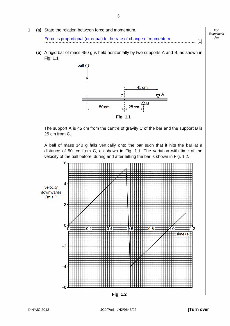
(b) A rigid bar of mass 450 g is held horizontally by two supports A and B, as shown in
Fig. 1.1.
Fig. 1.1
The support A is 45 cm from the centre of gravity C of the bar and the support B is
25 cm from C.
A ball of mass 140 g falls vertically onto the bar such that it hits the bar at a
distance of 50 cm from C, as shown in Fig. 1.1. The variation with time of the
velocity of the ball before, during and after hitting the bar is shown in Fig. 1.2.
Fig. 1.2
Force is proportional (or equal) to the rate of change of momentum.

4
© NYJC 2013 JC2/Prelim/H2/9646/02
For Examiner’s
Use
For the time that the ball is in contact with the bar, use Fig. 1.2 to determine
(i) the magnitude of the change in momentum of the ball,
change in momentum = ……………….. kg m s-1 [2]
(ii) the magnitude of the force exerted by the ball on the bar.
force by ball = ……………….. N [2]
(c) Hence, calculate the magnitude of the force exerted on the bar by support A for the
time that the ball is in contact with the bar.
force by support A = ……………….. N [2]
∆p = 140 x 10-3 [5.4 – (– 4.0)]
= 1.32 kg m s-1
∆
(
)( )
( )( ) N
Taking moments about B,
( ) ( )( ) ( )

5
© NYJC 2013 JC2/Prelim/H2/9646/02 [Turn over
For Examiner’s
Use
2 An unpowered artificial satellite of mass m has been placed in a stable orbit around the
Sun in the same direction as that of the Earth. It is at a distance of 0.99R from the Sun,
where R is the orbital radius of the Earth as shown in Fig. 2.1.
Fig. 2.1
(a) Ignore the very small force the satellite acts on the Earth. Show that the period of
the Earth round the Sun TE is given by
where MS is the mass of the Sun.
[2]
(b) Show that the resultant force on the satellite is given by 2
0.99 SGM m
R, given that the
mass of the Sun is 3.33 x 10⁵ times the mass of Earth.
5
2 2 2 2
2 2 2
( )3.33 101.02 10000
(0.99 ) (0.01 )
1.02 0.03 0.99
S
S SE
S S S
MG m
GM m GM mGM m xFR R R R
GM m GM m GM m
R R R
[2]
R
0.99R
Sun Earth
satellite
23/24
E
S
T RGM
2
2
2
2
23/2
2( )
2( )
4
S EE
E
S
E
E
S
GM MM R
TR
GMR
TR
T RGM

6
© NYJC 2013 JC2/Prelim/H2/9646/02
For Examiner’s
Use
(c) Hence determine the period of the satellite round the Sun in terms of the period of
the Earth TE.
Period of satellite = ………………………… [2]
(d) ‘Si c h i i g i g d h S i i , i i i q i i i m.’
Comment on the statement.
…………………………………………………………………………………………………
…………………………………………………………………………………………….. [1]
3 (a) State the principle of superposition.
…………………………………………………………………………………………………
…………………………………………………………………………………………………
……………………………………………………………………………………………... [1]
(b) Figure 3.1 shows a double slit S1 and S2 emitting waves of amplitude A and of
wavelength 590 nm. They are placed 0.800 mm apart and at a distance of 2.70 m
from a line XY. Point O is in the center of the fringe pattern. Two polarizers P1 and
P2 are placed in front of S1 and S2 respectively. The polarizers are rotated such that
a fringe pattern is observed along the line XY.
S1 0.800 mm
X Y O
2.70 m
S2
S
P1 P2
Fig. 3.1
The satellite is not in equilibrium because it has centripetal acceleration. Hence the
resultant force is not zero.
2
2
2
2
22
20.99 (0.99 )( )
2( )
4
S
S
E
S
GM mm R
TR
GMR
TR
T R TGM

7
© NYJC 2013 JC2/Prelim/H2/9646/02 [Turn over
For Examiner’s
Use
(i) Show that the fringe separation along the line XY is 2.00 mm. [1]
(ii) On Fig. 3.2, ignoring diffraction effects, sketch the variation of intensity along
the line XY. Label your values clearly on the axes. [2]
Fig. 3.2
(c) The polarizer P1 is rotated 90o along its plane.
(i) Calculate the resultant amplitude at point O on the line XY in terms of A.
amplitude = …………… [1]
X 4 3 2 1 0 1 2 3 4 Y
intensity
mm

8
© NYJC 2013 JC2/Prelim/H2/9646/02
For Examiner’s
Use
(ii) Calculate the resultant amplitude at a point 1.00 mm from point O along the line
XY in terms of A.
amplitude = …………… [1]
(iii) Describe the appearance of the fringe pattern.
……………………………………………………………………………………………
………………………………………………………………………………………... [1]
4 An ideal transformer has 5000 turns on its primary coil. It is used to convert a main
supply of root mean square value of 230 V to an alternating voltage having a peak value
of 12.0 V.
(a) (i) Explain what is meant by root mean square value of 230 V.
…………………………………………………………………………………………..
…………………………………………………………………………………………..
………………………………………………………………………………………... [2]
(ii) Calculate the number of turns on the secondary coil.
number of turns = ……………….. [2]

9
© NYJC 2013 JC2/Prelim/H2/9646/02 [Turn over
For Examiner’s
Use
(b) The secondary coil is connected in series with a resistor R. The variation with time t,
in seconds, of the potential difference at the secondary coil is given by the
expression
V = 12.0 sin(380t)
(i) Determine the frequency of the supply.
frequency = ……………….. Hz [1]
(ii) To prevent overheating, the mean power dissipated in R must not exceed
300W. Calculate the minimum resistance of R.
resistance = ……………….. Ω [2]
5 (a) A uniform magnetic field has constant flux density B. A straight wire of fixed length
carries a current I at an angle θ to the magnetic field as shown in Fig. 5.1.
Fig. 5.1
(i) Define the term magnetic flux density.
……………………………………………………………………………………………
………………………………………………………………………………………... [1]
It is the force per unit length experienced by a straight conductor carrying unit
current when the conductor is placed at right angles to the magnetic field.

10
© NYJC 2013 JC2/Prelim/H2/9646/02
For Examiner’s
Use
(ii) The current I in the wire is changed, keeping the angle θ constant.
On Fig. 5.2, sketch a graph to show the variation with the current I of the force
F on the wire. [1]
Fig. 5.2
(iii) The angle θ between the wire and the magnetic field is now varied. The current
I is kept constant.
On Fig. 5.3, sketch a graph to show the variation with angle θ of the force F on
the wire. [1]
Fig. 5.3

11
© NYJC 2013 JC2/Prelim/H2/9646/02 [Turn over
For Examiner’s
Use
(b) Negative ions are travelling through a vacuum in a narrow beam. The ions enter a
region of uniform magnetic field of flux density B and are deflected in a semi-circular
arc, as shown in Fig. 5.4.
Fig. 5.4
The ions, travelling with speed 1.40 × 10⁵ m s-1, are detected at a fixed detector
when the diameter of the arc in the magnetic field is 12.8 cm.
(i) By reference to Fig. 5.4, state the direction of the magnetic field.
………………………………………………………………………………………... [1]
(ii) The ions have mass 20u and charge – 1.6 × 10⁻¹⁹ C. Show that the magnetic
flux density is 0.454 T. Explain your working.
[2]
(iii) Ions of a larger mass with the same charge and speed as those in (b)(ii) are
also present in the beam. On Fig. 5.4, sketch the path of these ions in the
magnetic field of magnetic flux density 0.454 T. [1]
beam of
negative ions
detector uniform magnetic
field
Out of the plane of the paper.
( )( )
( ) (
)
Since the magnetic force on the ions provide for its centripetal force,

12
© NYJC 2013 JC2/Prelim/H2/9646/02
For Examiner’s
Use
6 Fig. 6.1 shows a simple circuit. The resistance of the lamp is 20 Ω and it requires a minimum of 60 V to light up.
Fig. 6.1
Fig. 6.2 shows how the current I through the light dependent resistor varies with the
potential difference V across it when different intensities of light fall onto it.
Fig. 6.2
-10
-8
-6
-4
-2
0
2
4
6
8
10
-200 -150 -100 -50 0 50 100 150 200
240 V
30 10
20
V / V
I / A 10000 W m-2
20 W m-2
100 W m-2
5000 W m-2
2500 W m-2

13
© NYJC 2013 JC2/Prelim/H2/9646/02 [Turn over
For Examiner’s
Use
(a) Calculate the current through the 30 Ω resistor when the potential difference across
the lamp is 40 V.
40
30 10
1.0 A
VI
R
current = ……………………… A [2]
(b) Explain how the above circuit can be used as a warning system for an environment
which requires low intensity light.
…………………………………………………………………………………………………
…………………………………………………………………………………………………
…………………………………………………………………………………………….. [2]
If the intensity of the light in the environment is high, the resistance of the light
dependent resistor will be low. This will cause the potential difference across the
lamp to be more than 50 V, causing the lamp to light up, indicating that the
intensity of the light in the environment is high.

14
© NYJC 2013 JC2/Prelim/H2/9646/02
For Examiner’s
Use
(c) Using Fig. 6.2, determine the intensity of light which will produce a potential
difference of 60 V across the lamp.
intensity = ……………………….. W m-2 [3]
Total resistance of parallel arrangement 11 1 1
( )40 20 20
8
Resistance of L.D.R: R
R
8240 60
8
24
intensity of 5000 W m-2.
OR
If the p.d across the lamp is 60 V, the p.d. across the L.D.R will be 240 – 60 = 180
V. If we have the current flowing through the L.D.R when its p.d. is 180 V, we can
look for the point on Fig. 6.2 and determine which graph and which ntensity.
Total resistance of parallel arrangement 11 1 1
( )40 20 20
8
Current flowing through the L.D.R: 60
7.5 A 8
I
From the graph, the graph which shows a current of 7.5 A at 180 V is the one with
an intensity of 5000 W m-2.

15
© NYJC 2013 JC2/Prelim/H2/9646/02 [Turn over
For Examiner’s
Use
7 Wind power can be used for the generation of electric power. Fig 7.1 and Fig 7.2 illustrate a particular type of wind turbine.
Table 7.3 shows some information provided by the manufacturer.
Table 7.3
Height of tower (ground to hub) 80 m
Blade length 45 m
Number of blades 3
Rated power 3 MW
Voltage 650 V
Frequency 50 Hz
gearbox
generator
generator
housing
drive
shaft
drive
shaft
hub
Fig 7.2
Fig 7.1

16
© NYJC 2013 JC2/Prelim/H2/9646/02
For Examiner’s
Use
Fig 7.4 shows the wind turbine power curve provided by the manufacturer.
Fig 7.4
(a) Using the information provided in Table 7.3, calculate
(i) the height of the lowest point of the rotor above the ground, height = ……………………. m [1]
(ii) the area swept by the rotor blades
area = ……………………. m2 [1]
(iii) the period of revolution of the rotor when the wind speed is 10 m s1, given that
the ratio of the speed of the blade tip to the wind speed is 7.
period = ……………………. s [2]
Height = 80 – 45 = 35 m
Sweep area = π × 452 = 6.36×10³ m2
Blade tip speed = 7 × 10 = 70 m s1
Period = × (2 × 45) / 70 = 4.0 s

17
© NYJC 2013 JC2/Prelim/H2/9646/02 [Turn over
For Examiner’s
Use
(b) (i) Discuss, with reasons, if the rated power of 3 MW is a fair value.
……………………………………………………………………………………………
……………………………………………………………………………………………
……………………………………………………………………………………………
……………………………………………………………………………………….. [2]
(ii) The average monthly electrical energy consumption per household in
Singapore is 470 kW h. Calculate the number of homes one wind turbine can
serve when operating at the rated power.
number of homes = ……………………. [2]
(c) (i) Using the information provided in Fig 7.4, obtain values for
1. the maximum power output,
maximum power = ……………………. MW [1]
2. the wind speed for this power.
wind speed = ……………………. m s1 [1]
(ii) The incident wind power E, which is the kinetic energy of the air incident on the
rotor to turn the blades per unit time, is given by
E = k L2 v3
where L is the blade length of the turbine,
v is the incident wind speed, and
k is a constant of value 1.96 kg m3
Calculate, for the turbine operating at maximum output power, the incident wind
power.
incident wind power = ……………………. W [1]
The turbine is able to produce more than the rated power for wind speeds
between 12 m s–1 and 25 m s–1.
For sites with wind speeds averaging above 12 m s–1, the rated power will be
a fair value.
Power consumption per household = 470 ÷ (30 × 24)
= 0.65 kW
No of homes = 3000 ÷ 0.65 = 4600
E = 1.96 × 452 × 153
= 1.34×10⁷ J s-1

18
© NYJC 2013 JC2/Prelim/H2/9646/02
For Examiner’s
Use
(iii) Acc di g z’ L w, which i d iv d f m h i ci f c v i f
mass and momentum, the maximum amount of the incident wind kinetic energy
that can be captured by a wind turbine is 59.3%.
Suggest one evidence that not all of the incident wind energy can be captured.
……………………………………………………………………………………………
………………………………………………………………………………………... [1]
(iv) Calculate the efficiency of the wind turbine in converting the accessible kinetic
energy to electrical energy when operating under the conditions stated in (i).
efficiency = ……………………. % [2]
(d) The wind turbine, like most others, has a cut-out speed. This means that at high
wind speeds, the gearbox disengages the generator from the rotor and the
generator is no longer turned by the rotor.
(i) Use Fig 7.4 to determine the cut-out speed.
cut-out speed = ……………………. m s1 [1]
(ii) Suggest one reason why it is necessary to have a cut-out speed.
……………………………………………………………………………………………
………………………………………………………………………………………... [1]
(e) Wind turbines are usually erected in wide open spaces. As such, they are
vulnerable to (i) strong winds which may cause the rotor to rotate too fast and be
damaged, and (ii) lightning which may strike the rotor, causing damage.
For each of the hazards mentioned, suggest how the risk of damage to the rotor
may be minimized.
(i) Strong winds
……………………………………………………………………………………………
………………………………………………………………………………………... [1]
(ii) Lightning
……………………………………………………………………………………………
………………………………………………………………………………………... [1]
The wind will still be moving, albeit at a lower speed, after passing through the
rotor. Thus it could not have lost all of its kinetic energy.
The generators are designed to take a certain maximum electrical load.
Having a cut-out speed will prevent the circuit from being overloaded and
damaged.
Install brakes to resist rotation.
Turn the blades to face away from the wind.
Use poor electrical conductor such as fiberglass for blades.
Install lightning rods taller than the turbine nearby.
Accessible wind power = 0.593 × 1.34×107
= 7.94×10⁶ W
Efficiency = 3.0×10⁶ / 7.94×106
= 38%

19
© NYJC 2013 JC2/Prelim/H2/9646/02 [Turn over
For Examiner’s
Use
8. Fig. 8.1 shows a coil (coil X).
A student winds another coil (coil Y) tightly around coil X. A changing e.m.f. in coil X induces an e.m.f. in coil Y. The student wishes to investigate how the e.m.f. V in coil Y depends on the frequency f of the current in coil X. It is suggested that V is directly proportional to f. Design a laboratory experiment to investigate the suggested relationship. You should
draw a diagram, in the space provided below, showing the arrangement of your
equipment. In your account you should pay particular attention to:
(a) the procedure to be followed,
(b) the measurements to be taken,
(c) the control of variables,
(d) the analysis of the data,
(e) the safety precautions to be taken.
Diagram
Fig. 8.1

20
© NYJC 2013 JC2/Prelim/H2/9646/02
For Examiner’s
Use
……………………………………………………………………………………………………………
……………………………………………………………………………………………………………
……………………………………………………………………………………………………………
……………………………………………………………………………………………………………
……………………………………………………………………………………………………………
……………………………………………………………………………………………………………
……………………………………………………………………………………………………………
……………………………………………………………………………………………………………
……………………………………………………………………………………………………………
……………………………………………………………………………………………………………
……………………………………………………………………………………………………………
……………………………………………………………………………………………………………
……………………………………………………………………………………………………………
……………………………………………………………………………………………………………
.…………………………………………………………………………………………………………..
…….……………………………………………………………………………………………………..
……………………………………………………………………………………………………………
……………………………………………………………………………………………………………
………..………………………………………………………………………………………………….
……………………………………………………………………………………………………………
……………………………………………………………………………………………………………
……….…………………………………………………………………………………………………..
……………………………………………………………………………………………………………
……………………………………………………………………………………………………………
………..………………………………………………………………………………………………….
……………………………………………………………………………………………………………
……………………………………………………………………………………………………………
………..………………………………………………………………………………………………….

21
© NYJC 2013 JC2/Prelim/H2/9646/02 [Turn over
For Examiner’s
Use
……………………………………………………………………………………………………………
……………………………………………………………………………………………………………
………..………………………………………………………………………………………………….
……………………………………………………………………………………………………………
……………………………………………………………………………………………………………
………..………………………………………………………………………………………………….
……………………………………………………………………………………………………………
……………………………………………………………………………………………………………
………..………………………………………………………………………………………………….
……………………………………………………………………………………………………………
……………………………………………………………………………………………………………
………..………………………………………………………………………………………………….
……………………………………………………………………………………………………………
……………………………………………………………………………………………………………
……………………………………………………………………………………………………………
……………………………………………………………………………………………………………
……………………………………………………………………………………………………………
……………………………………………………………………………………………………………
……………………………………………………………………………………………………………
……………………………………………………………………………………………………………
……………………………………………………………………………………………………………
……………………………………………………………………………………………………………
……………………………………………………………………………………………………………
……………………………………………………………………………………………………………
……………………………………………………………………………………………………………
……………………………………………………………………………………………………………
……………………………………………………………………………………………………………
……………………………………………………………………………………………………… [12]


![NAME: TOPIC: Maclaurin Series...Example 13 [NYJC Prelim/2014/P2/Q3] Given that =ln√1+ 1+ , where −1](https://img.dokumen.tips/doc/110x75/60e2151344e24674d40ea6f2/name-topic-maclaurin-series-example-13-nyjc-prelim2014p2q3-given-that.jpg)