Embed Size (px)
Citation preview

Research ArticlePhysical Analysis of the Initial Core and Running-In Phase forPebble-Bed Reactor HTR-PM
Jingyu Zhang,1 Fu Li,2 and Yuliang Sun2
1School of Nuclear Science and Engineering, North China Electric Power University, Beijing 102206, China2Institute of Nuclear and New Energy Technology, Tsinghua University, Beijing 100084, China
Correspondence should be addressed to Jingyu Zhang; [email protected]
Received 19 December 2016; Revised 9 March 2017; Accepted 23 March 2017; Published 16 April 2017
Academic Editor: Rafael Miro
Copyright © 2017 Jingyu Zhang et al. This is an open access article distributed under the Creative Commons Attribution License,which permits unrestricted use, distribution, and reproduction in any medium, provided the original work is properly cited.
The pebble-bed reactorHTR-PM is being built in China and is planned to be critical in one or two years. At present, one emphasis ofengineering design is to determine the fuel management scheme of the initial core and running-in phase. There are many possibleschemes, and many factors need to be considered in the process of scheme evaluation and analysis. Based on the experience fromthe constructed or designed pebble-bed reactors, the fuel enrichment and the ratio of fuel spheres to graphite spheres are important.In this paper, some relevant physical considerations of the initial core and running-in phase of HTR-PM are given. Then a typicalscheme of the initial core and running-in phase is proposed and simulated with VSOP code, and some key physical parameters,such as the maximum power per fuel sphere, the maximum fuel temperature, the refueling rate, and the discharge burnup, arecalculated. Results of the physical parameters all satisfy the relevant design requirements, whichmeans the proposed scheme is safeand reliable and can provide support for the fuel management of HTR-PM in the future.
1. Introduction
Modular high-temperature gas-cooled reactor (HTGR) is akind of safe and advanced nuclear energy system, whichcan efficiently provide electric power and high-temperatureprocess-heat. On February 15, 2008, Chinese State Councilapproved the implementation plan of HTGR demonstrationproject. The goal is to build a 200MWe demonstrationplant, named high-temperature gas-cooled reactor-pebble-bed module (HTR-PM), as the first one meeting the safetystandards of Generation-IV reactors in the world [1].
At present, the physical design of the equilibrium core ofHTR-PM has been finished by Institute of Nuclear and NewEnergy Technology (INET) of Tsinghua University, whichincludes that the fuel spheres with 8.5% enrichment areadopted, pass through the core for 15 times, and reach theaverage discharge burnup of 90000MWd/tU. The emphasisin work is transferred to determine the scheme of the initialcore and running-in phase.
From the initial core with fresh fuel, HTR-PM needsto take years of continuous refueling and burnup to reachthe stable equilibrium core. Spending this time safely is
the important research content of in-core fuel managementand is an actual technical problem in pressing need ofsolution. There are many possible schemes for the initialcore and running-in phase, and many factors need to beconsidered in the process of scheme evaluation and anal-ysis. Before HTR-PM, some design schemes of pebble-bedreactors have been proposed, including THTR-300 [2] fromHochtemperatur-Kernkraftwerk GmbH in Germany, HTR-10 [3] from Tsinghua University in China, HTR-Module [4]from Siemens AG in Germany, and PBMR [5] from PBMR(Pty) Ltd. in South Africa. Although the detailed designschemes of the initial core and running-in phase are differentfrom each other, the common experience of these pebble-bedreactors shows that the fuel enrichment and the ratio of fuelspheres to graphite spheres are important.
In this paper, the physical model and simulation tool ofHTR-PM are described in Section 2. The physical considera-tions of the initial core and running-in phase are, respectively,described in Sections 3 and 4. Then a typical scheme of theinitial core and running-in phase is proposed and analyzedin Section 5. In the last section, a comprehensive comment ispresented.
HindawiScience and Technology of Nuclear InstallationsVolume 2017, Article ID 8918424, 6 pageshttps://doi.org/10.1155/2017/8918424

2 Science and Technology of Nuclear Installations
Table 1: Main design parameters of HTR-PM.
Parameters Units ValuesReactor total thermal power MWth 2 × 250Active core diameter m 3Equivalent active core height m 11Primary helium pressure MPa 7Helium temperature at reactor inlet/outlet ∘C 250/750Uranium loading per fuel sphere g 7Enrichment of fresh fuel spheres % 8.5Diameter of fuel spheres cm 6Number of fuel spheres in one reactor core 420,000Average discharge burnup GWd/tU 90
2. Physical Model and Simulation Tool
2.1. Physical Model. The main technical parameters of HTR-PM are presented in Table 1.
HTR-PM uses helium as coolant and graphite as moder-ator as well as structural material. Its spherical fuel elementscontain thousands of very small “coated particles” which areembedded in the graphite matrix. The pebble-bed designallows fuel spheres to constantly pass the core by gravity froman up direction to a down direction, which ensures that theoperation mode of continuous fuel loading and dischargingis available without shutting down the reactor.
HTR-PM adopts the cylindrical single zone core. Theceramic structures surrounding the reactor core consist ofthe inner graphite reflector and outer carbon brick layers, asshown in Figure 1. The whole ceramic internals are installedinside a metallic core barrel, which itself is supported byreactor pressure vessel (RPV). The metallic core barrel andthe RPV are protected against high temperature from the coreby the cold helium borings of the side reflector, which act likea shielding temperature screen.
HTR-PM adopts multipass refueling strategy. The fuelspheres drop into the reactor core from the central fuelloading tube and are discharged through a fuel extractionpipe at the core bottom. Subsequently, the discharged fuelspheres pass the burnup measurement facility one by one.Depending on their burnup, either they will be dischargedand transported into the spent fuel storage tank when havingreached their designed burnup, or they will be reinserted intothe reactor to pass the core once again.
2.2. Simulation Tool. VSOP [6] code is developed by theInstitute for Safety Research and Reactor Technology, JuelichResearch Center, Germany. The code has been widely usedfor the design of the high-temperature reactor (HTR) withspherical fuel elements, such as THTR-300 andHTR-Modulein Germany, PBMR in South Africa, and HTR-10 in China.The application of the code includes the setup of the reactorand of the fuel element, processing of cross sections, neutronspectrum evaluation, neutron diffusion calculation in two orthree dimensions, fuel depletion, fuel shuffling, reactor con-trol, and thermal hydraulics of steady states and transients.The code can simulate the reactor operation from the initialcore towards the equilibrium core.
Top carbon brick
Top re�ector
Void
Pebble bed
Cone
Bottom re�ector
Side
re�e
ctor
Side
carb
on b
rick
Fuel
load
ing
tube
Fuel
extr
actio
n pi
pe
R
Z
Bottom carbon brick
Figure 1: Geometric structure of HTR-PM core.
In VSOP code, to simulate the multipass refueling strat-egy of pebble-bed reactor, the reactor core is divided intodifferent channels along the radial direction and differentlayers along the axial direction. Thus, lots of material regionsare produced, which are the basic unit of neutron spectrumcalculation. Then, each material region is divided into dif-ferent fuel batches, which are the basic unit of fuel burnupcalculation and fuel shuffling, and the number of fuel batchesin material region is chosen as the designed times of fuelcycles.When the reactor is running, at the bottomof the core,the fuel batches with highest burnup will be discharged, andother fuel batches will be sent back to the top of the core, andmeanwhile the bathes of fresh fuel will be loaded at the top ofthe core to keep the total quantity of fuel spheres stable. In themiddle of the core, the fuel batches of each material regionwill be shuffled down to its neighbouring material regionalong the channel. Through the above method, the multipassrefueling strategy of pebble-bed reactor can bewell simulated.More detailed information can be seen in [6, 7].
Through the long-term validation and verification in the10MWth high-temperature gas-cooled test reactor (HTR-10)as well as continuous updating by INET [8], VSOP code isthought to be capable of satisfying the requirements of HTR-PM physical design.
3. Physical Considerations of the Initial Core
3.1. Loading Patterns of the Initial Core. The initial core isdefined as the core that contains only the fresh fuel spheres,
Science and Technology of Nuclear Installations 3
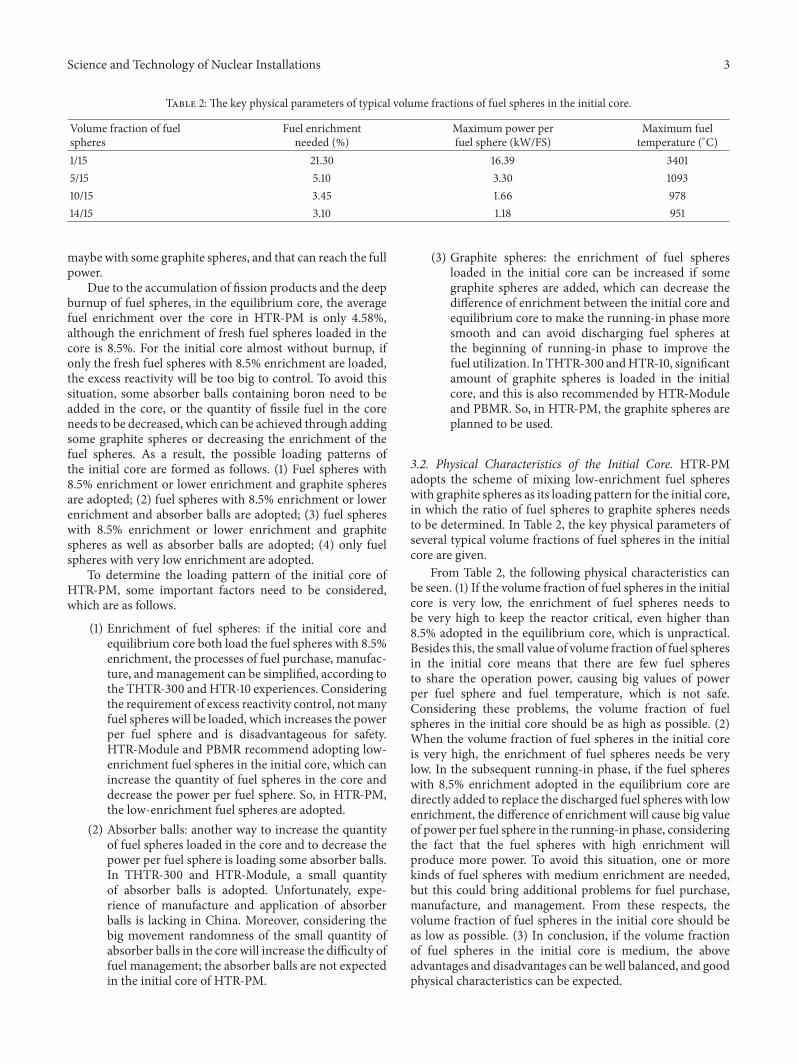
Table 2: The key physical parameters of typical volume fractions of fuel spheres in the initial core.
Volume fraction of fuelspheres
Fuel enrichmentneeded (%)
Maximum power perfuel sphere (kW/FS)
Maximum fueltemperature (∘C)
1/15 21.30 16.39 34015/15 5.10 3.30 109310/15 3.45 1.66 97814/15 3.10 1.18 951
maybe with some graphite spheres, and that can reach the fullpower.
Due to the accumulation of fission products and the deepburnup of fuel spheres, in the equilibrium core, the averagefuel enrichment over the core in HTR-PM is only 4.58%,although the enrichment of fresh fuel spheres loaded in thecore is 8.5%. For the initial core almost without burnup, ifonly the fresh fuel spheres with 8.5% enrichment are loaded,the excess reactivity will be too big to control. To avoid thissituation, some absorber balls containing boron need to beadded in the core, or the quantity of fissile fuel in the coreneeds to be decreased, which can be achieved through addingsome graphite spheres or decreasing the enrichment of thefuel spheres. As a result, the possible loading patterns ofthe initial core are formed as follows. (1) Fuel spheres with8.5% enrichment or lower enrichment and graphite spheresare adopted; (2) fuel spheres with 8.5% enrichment or lowerenrichment and absorber balls are adopted; (3) fuel sphereswith 8.5% enrichment or lower enrichment and graphitespheres as well as absorber balls are adopted; (4) only fuelspheres with very low enrichment are adopted.
To determine the loading pattern of the initial core ofHTR-PM, some important factors need to be considered,which are as follows.
(1) Enrichment of fuel spheres: if the initial core andequilibrium core both load the fuel spheres with 8.5%enrichment, the processes of fuel purchase, manufac-ture, andmanagement can be simplified, according tothe THTR-300 andHTR-10 experiences. Consideringthe requirement of excess reactivity control, notmanyfuel spheres will be loaded, which increases the powerper fuel sphere and is disadvantageous for safety.HTR-Module and PBMR recommend adopting low-enrichment fuel spheres in the initial core, which canincrease the quantity of fuel spheres in the core anddecrease the power per fuel sphere. So, in HTR-PM,the low-enrichment fuel spheres are adopted.
(2) Absorber balls: another way to increase the quantityof fuel spheres loaded in the core and to decrease thepower per fuel sphere is loading some absorber balls.In THTR-300 and HTR-Module, a small quantityof absorber balls is adopted. Unfortunately, expe-rience of manufacture and application of absorberballs is lacking in China. Moreover, considering thebig movement randomness of the small quantity ofabsorber balls in the core will increase the difficulty offuel management; the absorber balls are not expectedin the initial core of HTR-PM.
(3) Graphite spheres: the enrichment of fuel spheresloaded in the initial core can be increased if somegraphite spheres are added, which can decrease thedifference of enrichment between the initial core andequilibrium core to make the running-in phase moresmooth and can avoid discharging fuel spheres atthe beginning of running-in phase to improve thefuel utilization. In THTR-300 andHTR-10, significantamount of graphite spheres is loaded in the initialcore, and this is also recommended by HTR-Moduleand PBMR. So, in HTR-PM, the graphite spheres areplanned to be used.
3.2. Physical Characteristics of the Initial Core. HTR-PMadopts the scheme of mixing low-enrichment fuel sphereswith graphite spheres as its loading pattern for the initial core,in which the ratio of fuel spheres to graphite spheres needsto be determined. In Table 2, the key physical parameters ofseveral typical volume fractions of fuel spheres in the initialcore are given.
From Table 2, the following physical characteristics canbe seen. (1) If the volume fraction of fuel spheres in the initialcore is very low, the enrichment of fuel spheres needs tobe very high to keep the reactor critical, even higher than8.5% adopted in the equilibrium core, which is unpractical.Besides this, the small value of volume fraction of fuel spheresin the initial core means that there are few fuel spheresto share the operation power, causing big values of powerper fuel sphere and fuel temperature, which is not safe.Considering these problems, the volume fraction of fuelspheres in the initial core should be as high as possible. (2)When the volume fraction of fuel spheres in the initial coreis very high, the enrichment of fuel spheres needs be verylow. In the subsequent running-in phase, if the fuel sphereswith 8.5% enrichment adopted in the equilibrium core aredirectly added to replace the discharged fuel spheres with lowenrichment, the difference of enrichment will cause big valueof power per fuel sphere in the running-in phase, consideringthe fact that the fuel spheres with high enrichment willproduce more power. To avoid this situation, one or morekinds of fuel spheres with medium enrichment are needed,but this could bring additional problems for fuel purchase,manufacture, and management. From these respects, thevolume fraction of fuel spheres in the initial core should beas low as possible. (3) In conclusion, if the volume fractionof fuel spheres in the initial core is medium, the aboveadvantages and disadvantages can be well balanced, and goodphysical characteristics can be expected.

4 Science and Technology of Nuclear Installations
4. Physical Considerations ofthe Running-In Phase
There are some basic considerations for the refueling patternsof the running-in phase of HTR-PM.
(1) The process of replacing the graphite spheres and theprocess of replacing the low-enrichment fuel spheresloaded in the initial core should be separated, whichis beneficial for stabilizing the running-in phase andsimplifying the operation of the fuel handling andstorage system (FHSS). This is recommended byHTR-Module and PBMR.
(2) The process of replacing the graphite spheres withfuel spheres should be performed at the beginningof running-in phase, which can quickly increase thequantity of fuel spheres in the core and thus decreasethe power per fuel sphere and can avoid dischargingfuel spheres at the beginning of running-in phase toimprove fuel utilization. This is performed in THTR-300 and HTR-10 and is recommended by HTR-Module and PBMR.
(3) For simplifying the processes of fuel purchase, man-ufacture, and management, it is better to use asfew kinds of fuel spheres in enrichment as possiblein the running-in phase. In HTR-Module, threekinds of fuel spheres are recommended, includingthe low-enrichment fuel spheres loaded in the initialcore, the medium-enrichment fuel spheres used inthe running-in phase, and the high-enrichment fuelspheres adopted in the equilibrium core.
(4) In the running-in phase, the times of fuel cyclesshould be as many as possible, which can smooth thepower distribution and burnup distribution along theaxial direction of the core [9], but the refueling rateshould be controlled in the capability of FHSS.
5. Physical Analysis of a Typical Scheme ofthe Initial Core and Running-In Phase
5.1. Description of the Scheme. Based on the above physicalconsiderations of the initial core and running-in phase, atypical scheme for HTR-PM is proposed as follows.
(1) The initial core is made up of the fuel sphereswith 4.1% enrichment and the graphite spheres. Thevolume fraction of fuel spheres in the core is 7/15.
(2) The running-in phase is divided into three continuousprocesses. In the first process, 3/8 of the graphitespheres are replaced by the fuel spheres with 4.1%enrichment. When the first process is ended, thevolume fraction of fuel spheres in the core is improvedto 10/15. In the second process, the remaining graphitespheres are replaced by the fuel spheres with 4.1%enrichment. When the second process is ended, theyare full of fuel spheres with 4.1% enrichment in thecore. The last process includes 15 fuel cycles. In eachcycle, 1/15 of the fuel sphereswith 4.1% enrichment are
200 400 600 800 1000 12000Time (d)
1.2
1.4
1.6
1.8
2.0
2.2
2.4
2.6
Max
imum
pow
er p
er fu
el sp
here
(kW
/FS)
Figure 2: Maximum power per fuel sphere changing with time.
replaced by the fuel spheres with 8.5% enrichment.When this process is ended, they are full of fuelspheres with 8.5% enrichment in the core, and thestatus is close to the equilibrium core.
5.2. Physical Characteristics of the Scheme. The above schemeis simulated with VSOP code, and the key physical parame-ters, such as the maximum power per fuel sphere, the maxi-mum fuel temperature, the refueling rate, and the dischargeburnup, are calculated.
Results of the maximum power per fuel sphere in therunning-in phase are shown in Figure 2.
In the running-in phase, the maximum power per fuelsphere reaches 2.49 kW/FS, which is higher than that in theequilibrium core (1.81 kW/FS), but there is still some margincompared with the safety limit value (3.5 kW/FS).
There are two obvious peak values of themaximumpowerper fuel sphere in the running-in phase.The first one appearsat the beginning of running-in phase. That is mainly becausethe fuel spheres loaded in the core are very few at that time,and the peak value becomes smaller along with adding fuelspheres. The second peak value appears at the time of addingthe fuel sphereswith 8.5% enrichment.That ismainly becausethe enrichment of the new added fuel spheres is much higherthan the depleted fuel spheres, which means the new addedfuel spheres share a great part of operation power.
Results of themaximum fuel temperature in the running-in phase are shown in Figure 3.
In the running-in phase, the maximum fuel temperaturereaches 1022∘C, which is higher than that in the equilibriumcore (932∘C), but there is still some margin compared withthe safety limit value (1200∘C).
Results of the refueling rate in the running-in phase areshown in Figure 4.
In the running-in phase, the refueling rate is controlledin the capability of FHSS, that is, lower than 12000 FS/d. Itcan be seen that, at the beginning of running-in phase, therefueling rate is very high, which is because the fissile fuelloaded in the core is much less than that in the equilibrium

Science and Technology of Nuclear Installations 5M
axim
um fu
el te
mpe
ratu
re(∘
C)
920
940
960
980
1000
1020
1040
200 400 600 800 1000 12000Time (d)
Figure 3: Maximum fuel temperature changing with time.
200 400 600 800 1000 12000Time (d)
4000
5000
6000
7000
8000
9000
10000
11000
Refu
elin
g ra
te (F
S/d)
Figure 4: Refueling rate changing with time.
core. It makes the reactivity decrease with burnup fasterthan that in the equilibrium core, and thus higher refuelingrate is needed to maintain normal operation of the reactor.And at the beginning of running-in phase, the refueling ratefluctuates widely, which is because the power distributionand burnup distribution along the axial direction of the corehave not been flattened well during this period. But, withthe development of the running-in phase, the compositionand burnup in the core are getting more and more well-distributed, resulting in smaller fluctuation of the refuelingrate.
Results of the discharge burnup in the running-in phaseare shown in Figure 5.
In the running-in phase, the discharge burnup is lowerthan the safety limit value (100000MWd/tU). At 143.9 days,all the graphite spheres are discharged, and then the depletedlow-enrichment fuel spheres start to be discharged and theinitial discharge burnup is 16281MWd/tU.The discharge bur-nup climbs to 57342MWd/tU with operation of the reactor.At 1118.2 days, all of the depleted low-enrichment fuel spheresare discharged, and then the depleted high-enrichment fuel
0100002000030000400005000060000700008000090000
100000
Disc
harg
e bur
nup
(MW
d/tU
)
200 400 600 800 1000 12000Time (d)
Figure 5: Discharge burnup changing with time.
spheres start to be discharged and the discharge burnup isclose to that in the equilibrium core (90000MWd/tU).
The uncertainty quantification of the calculation resultsof VSOP code for HTR-PM design has been performed byINET, involving the uncertainties from nuclear data, pebbleflow [10], filling fraction of pebble bed [11], uranium loadingper fuel sphere, and some thermal-hydraulic parameters.Thecorresponding influence on the key physical parameters, suchas 𝑘eff , power density, power peak, axial offset of power (AO),fuel temperature, and fuel burnup, is detailedly evaluated.Theresults show that the maximum uncertainty for the situationof normal operation is less than 1.0% [12].
As to this paper, the calculation results of VSOP codefor the proposed scheme of the initial core and running-inphase are 10%∼20% lower than the safety limit values. So,after taking the corresponding uncertainties into account, thesafety margins are still enough.
6. Conclusions
In this paper, some physical considerations for the fuelmanagement of the initial core and running-in phase ofHTR-PM are given, including the advantages and disadvantagesof different loading patterns of the initial core and differentrefueling patterns of the running-in phase. Then a typicalscheme of the initial core and running-in phase ofHTR-PM isproposed, inwhich one kind of graphite sphere and two kindsof fuel spheres in enrichment are used. Firstly, the graphitespheres are replaced by low-enrichment fuel spheres throughtwo fuel cycles. When all the graphite spheres are discharged,the low-enrichment fuel spheres start to be replaced byhigh-enrichment fuel spheres through fifteen fuel cycles.When all the low-enrichment fuel spheres are discharged,the running-in phase is ended and the equilibrium core isestablished.The above scheme of the initial core and running-in phase is simulated with VSOP code, and some key physicalparameters, such as the maximum power per fuel sphere,the maximum fuel temperature, the refueling rate, and thedischarge burnup, are calculated. Results of the physicalparameters all satisfy the relevant design requirements, which

6 Science and Technology of Nuclear Installations
means the proposed scheme is safe and reliable. In thefuture, more detailed physical analysis of the scheme will beperformed, especially for the accident conditions.
Conflicts of Interest
The authors declare that there are no conflicts of interestregarding the publication of this paper.
Acknowledgments
The authors would like to express their gratitude for thesupport by National Natural Science Foundation of China(Project 11605058 and Project 11375099) and Chinese Na-tional S&T Major Project ZX06901.
References
[1] Z. Zhang, Z. Wu, D. Wang et al., “Current status and technicaldescription of Chinese 2 × 250 MWth HTR-PM demonstrationplant,” Nuclear Engineering and Design, vol. 239, no. 7, pp. 1212–1219, 2009.
[2] R. Baumer, I. Kalinowski, E. Rohler, J. Schoning, and W.Wachholz, “Construction and operating experience with the300-MW THTR nuclear power plant,” Nuclear Engineering andDesign, vol. 121, no. 2, pp. 155–166, 1990.
[3] Z. Wu, D. Lin, and D. Zhong, “The design features of the HTR-10,”Nuclear Engineering and Design, vol. 218, no. 1–3, pp. 25–32,2002.
[4] G. H. Lohnert, “Technical design features and essential safety-related properties of theHTR-module,”Nuclear Engineering andDesign, vol. 121, no. 2, pp. 259–275, 1990.
[5] J. F. M. Slabber and E. J. Mulder, “Loading of the PBMR initialcore and the transition into the equilibrium core,” inProceedingsof the International Congress on Advances in Nuclear PowerPlants (ICAPP ’05), Seoul, Republic of Korea, May 2005.
[6] H. J. Rutten, K. A.Haas,H. Brockmann, andW. Scherer,V.S.O.P.(99/05) Computer Code System for Reactor Physics and FuelCycle Simulation, Forschungszentrum Julich GmbH, 2005.
[7] Z. Wu and X. Jing, “Fuel management of HTR-10,” Journal ofTsinghua University (Science and Technology), vol. 41, no. 4-5,pp. 120–123, 2001 (Chinese).
[8] International Atomic Energy Agency, “Evaluation of high tem-perature gas cooled reactor performance: benchmark analysisrelated to the PBMR-400, PBMM, GT-MHR, HTR-10 and theASTRA critical facility,” Tech. Rep. IAEA-TECDOC-1694, 2013.
[9] B. Ling and Y. Yang, Theory of Nuclear Reactor Engineering,Atomic Press, Beijing, China, 1982 (Chinese).
[10] H. Chen, L. Fu, G. Jiong, S. Ximing, andW. Lidong, “Quantita-tive analysis of uncertainty from pebble flow in HTR,” NuclearEngineering and Design, vol. 295, pp. 338–345, 2015.
[11] H. Chen, L. Fu, G. Jiong, and W. Lidong, “Uncertainty andsensitivity analysis of filling fraction of pebble bed in pebblebed HTR,” Nuclear Engineering and Design, vol. 292, pp. 123–132, 2015.
[12] C. Hao, Uncertainty analysis in modeling of pebble bed HTR[ph.D. dissertation], Tsinghua University, Beijing, China, 2014(Chinese).

TribologyAdvances in
Hindawi Publishing Corporationhttp://www.hindawi.com Volume 2014
FuelsJournal of
Hindawi Publishing Corporationhttp://www.hindawi.com Volume 2014
Journal ofPetroleum Engineering
Hindawi Publishing Corporationhttp://www.hindawi.com Volume 2014
Industrial EngineeringJournal of
Hindawi Publishing Corporationhttp://www.hindawi.com Volume 2014
Power ElectronicsHindawi Publishing Corporationhttp://www.hindawi.com Volume 2014
Advances in
CombustionJournal of
Hindawi Publishing Corporationhttp://www.hindawi.com Volume 2014
Journal of
Hindawi Publishing Corporationhttp://www.hindawi.com Volume 2014
Renewable Energy
Submit your manuscripts athttps://www.hindawi.com
Hindawi Publishing Corporationhttp://www.hindawi.com Volume 2014
StructuresJournal of
International Journal of
RotatingMachinery
Hindawi Publishing Corporationhttp://www.hindawi.com Volume 2014
EnergyJournal of
Hindawi Publishing Corporationhttp://www.hindawi.com Volume 2014
Hindawi Publishing Corporation http://www.hindawi.com
Journal of
Volume 201Hindawi Publishing Corporation http://www.hindawi.com Volume 201
International Journal ofInternational Journal of
Hindawi Publishing Corporationhttp://www.hindawi.com Volume 2014
Nuclear InstallationsScience and Technology of
Hindawi Publishing Corporationhttp://www.hindawi.com Volume 2014
Solar EnergyJournal of
Hindawi Publishing Corporationhttp://www.hindawi.com Volume 2014
Wind EnergyJournal of
Hindawi Publishing Corporationhttp://www.hindawi.com Volume 2014
Nuclear EnergyInternational Journal of
Hindawi Publishing Corporationhttp://www.hindawi.com Volume 2014
High Energy PhysicsAdvances in
The Scientific World JournalHindawi Publishing Corporation http://www.hindawi.com Volume 2014