Embed Size (px)
DESCRIPTION
moment of inertia
Citation preview

1 | Page
E203: MOMENT OF INERTIA
FRISNEDI, Nadine T.
OBJECTIVE
Moment of Inertia is the measure of the resistance
that is being exerted by the rigid body during a
rotational motion.
The performed experiment aims to achieve two
objectives in which the one is to determine the
mass moment of inertia of a disk and ring.
Through the experiment, the students will be able
to gain more knowledge and appreciation about
the concepts about the moment of inertia and how
different is the moment of inertia of the disk and
the ring. Secondly, it about being able to compare
the difference of moment of inertia of solid disk
rotated at two different axes which is at the center
and along its diameter. Students will appreciate
the concept of moment of inertia and how it is
important in studying Physics. Students will also
learn how to compute the moment of inertia given
the data they have obtained.
MATERIALS AND METHODS
Figure 1. The materials and equipment used in the experiment.
Before conducting the experiment, it is necessary
to set up the equipment to be used. The rotating
platform was placed near the edge of the table.
Since the super pulley was already connected to
the mounting rod and also the photogate head
upon receiving the equipment it is easy to extend
the rod outward leaving only little part of it
connected to the platform. Although the rod was
pulled outward it should be secured in place. The
second step is to change where on cylindrical part
of the vertical shaft the thread should be looped
around, which the uppermost cylinder slot is. After
changing the thread’s position, the mass hanger
which is connected to it should pass over the super
pulley. The rod should be adjusted so that it is
aligned to the thread after it is placed over the
pulley. The diameter of the cylindrical part of the
shaft where the thread is looped around is
measured using the Vernier caliper. This is needed
in order to get the experimental moment of
inertia. The radius of the disk was also measured
using the Vernier caliper. The disk was placed onto
the vertical shaft.
Figure 2. Setting up the rotating platform at the edge of the
table with the rod extended outward.
2 | P a g e
Figure 3. Measuring the radius of the disk using the Vernier
caliper.
In order to make sure that the rotating platform
with disk is leveled, an angle meter is used to
check it. Using the data cable, the smart tier is
connected to the head of the photogate.
Figure 4. Leveling the rotating platform using the angle meter.
The first part of the experiment is to know the
moment of inertia of disk and ring that is rotated
about the center. The ring is then placed on the
slot that is on top of the disk. Since the disk with
the ring on top of it is not moving due to kinetic
friction, a force it needed to overcome it. To let the
mass hanger drop on a constant speed, a small
amount of mass be added to it in which it is called
the friction mass. To get the friction mass, small
amounts should be placed onto the mass hanger
until it is seen to move at a constant speed.
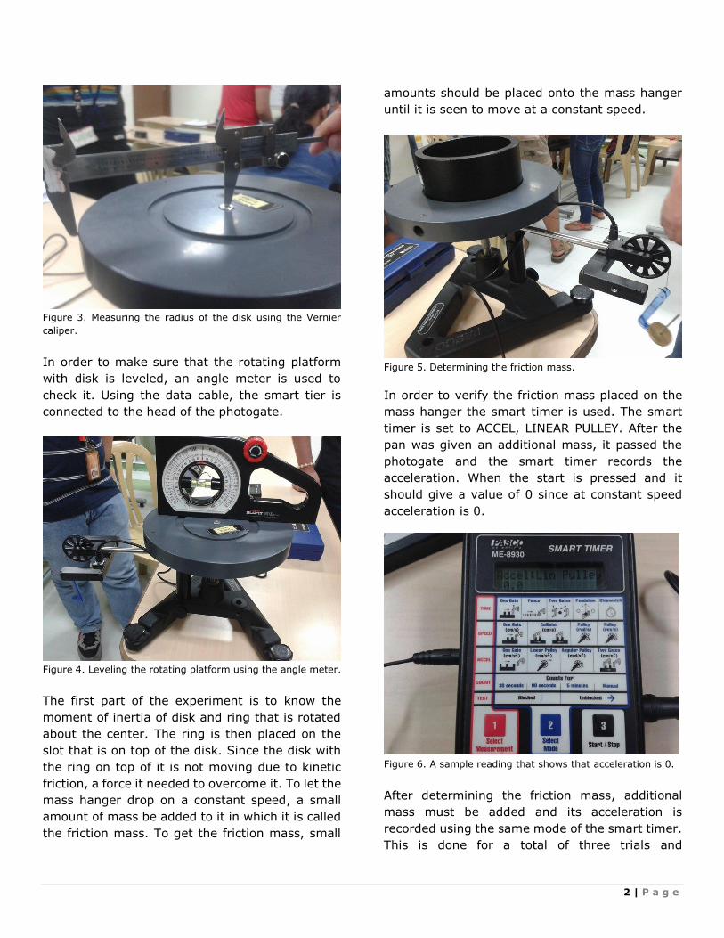
Figure 5. Determining the friction mass.
In order to verify the friction mass placed on the
mass hanger the smart timer is used. The smart
timer is set to ACCEL, LINEAR PULLEY. After the
pan was given an additional mass, it passed the
photogate and the smart timer records the
acceleration. When the start is pressed and it
should give a value of 0 since at constant speed
acceleration is 0.
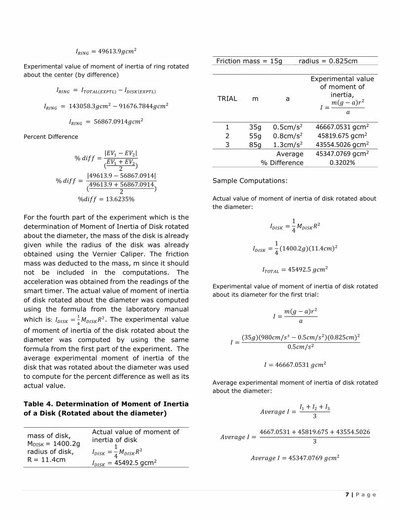
Figure 6. A sample reading that shows that acceleration is 0.
After determining the friction mass, additional
mass must be added and its acceleration is
recorded using the same mode of the smart timer.
This is done for a total of three trials and

3 | P a g e
increasing the mass on the pan every trial in order
to get the experimental value for the moment of
inertia of the disk and ring. It is necessary not to
include the amount of the friction mass when
doing calculations. The actual value using the
mass and radius of the disk and the ring as the
first variable while the average experimental
moment of inertia of disk and ring as the second
variable which is used in getting the percent
difference.
Figure 7. Determining the experimental moment of inertia of
the disk and ring.
Figure 8. A sample reading of the acceleration.
Moving on the next part of the experiment, in
which the procedure is the same from the first part
however, this time the ring was removed from the
disk. The friction mass must be obtained again for
this part since, it is only the disk that is used and
its moment of inertia being solved.
Additional mass is also added increasingly every
trial while its acceleration being recorded using the
smart timer in order to compute for its
experimental moment of inertia. The actual value
using the mass and radius of the disk as the first
variable while the average experimental moment
of inertia of disk as the second variable which is
used in getting the percent difference.
Figure 9. Determining the friction mass.
Figure 10. Determining the experimental the moment of inertia
of the disk.

4 | P a g e
Figure 11. A sample reading of the acceleration.
For the third part of the experiment which is about
getting the moment of inertia of the ring is to
subtract the average experimental value of the
moment of inertia of the disk from the moment of
inertia of the disk and ring combined. Since the
measurement of the inner and outer radius of the
ring is needed, the given diameter shown from the
list of materials is divided by 2. Percent Difference
was also computed. The actual moment of inertia
of the ring using its mass and radius as the first
variable while the computed experimental
moment of inertia from the difference between the
total Inertia and the Inertia of the disk alone as
the second variable.
For the last part of the experiment, the disk was
still used however, it used using a different
orientation. It was removed from being connected
to the vertical shaft and its D-shaped hole on its
side was inserted to the shaft instead. The
procedures for this part are also the same with the
second part of the experiment. The process is
repeated which is finding the friction mass of the
new set-up. Then additional mass was added to
the mass hanger and the smart timer was still
used in getting the acceleration. And as the mass
hanger drops, acceleration is recorded. The
experimental value of moment of inertia was
solved using the data gathered from the three
trials performed. The actual value using the mass
and radius of the disk as the first variable while
the average experimental moment of inertia of
disk as the second variable which is used in getting
the percent difference.
Figure 12. Determining the experimental moment of inertia of
the disk that is rotated about its diameter.
OBSERVATIONS AND RESULTS
For us to obtain the Moment of Inertia of Disk and
Ring that is rotated about the center, the mass of
the ring and disk were already given. The radius r
was measured using Vernier caliper. The radius of
the disk was measured using the Vernier Caliper
too. The inner and outer radius of the ring on the
other hand was obtained by dividing by two the
given inner and outer diameters of the ring. The
friction mass was deducted to the mass, m since
it should not be included in the computations. The
acceleration was obtained from the readings of the
smart timer.
By getting the sum of the moment of inertia of the
disk and the ring, we can get the actual value of
their moment of inertia. By using the formula that
is given from the laboratory manual which is: 𝐼 =𝑚(𝑔−𝑎)𝑟2
𝑎, we can solve for the experimental
moment of inertia. Then using the values that we
have obtained, we can calculate the percent
difference. This is one way to know or confirm if
the procedures were done properly to arrive with
closely related results.

5 | P a g e
Table 1. Determination of Moment of Inertia
of Disk and Ring (Rotated about the center)
mass of disk,
MDISK = 1400.2g
mass of ring,
MRING = 1428.2g
radius of disk,
R = 11.4cm
inner radius of ring,
R1 = 5.35cm
Outer radius,
R2 = 6.375cm
Actual value of
moment of inertia of
disk and ring
ITOTAL = IDISK + IRING
𝐼𝑇𝑂𝑇𝐴𝐿 =1
2𝑀𝐷𝐼𝑆𝐾𝑅2
+1
2𝑀𝑅𝐼𝑁𝐺(𝑅1
2 + 𝑅22)
𝐼𝑇𝑂𝑇𝐴𝐿 = 140598.9 gcm2
Friction mass = 25g radius = 0.825cm
TRIAL m a
Experimental value
of moment of
inertia,
𝐼 =𝑚(𝑔 − 𝑎)𝑟2
𝑎
1 55g 0.2cm/s2 183391.0031 gcm2
2 105g 0.6cm/s2 116655.7219 gcm2
3 155g 0.8cm/s2 129128.175 gcm2
Average 143058.3 gcm2
% Difference 1.7341%
Sample Computations:
Actual value of moment of inertia of the disk and ring
that is rotated about the center:
ITOTAL = IDISK + IRING
𝐼𝑇𝑂𝑇𝐴𝐿 =1
2𝑀𝐷𝐼𝑆𝐾𝑅2 +
1
2𝑀𝑅𝐼𝑁𝐺(𝑅1
2 + 𝑅22)
𝐼𝑇𝑂𝑇𝐴𝐿 =1
2(1400.2𝑔)(11.4𝑐𝑚)2 +
1
2(1428.2𝑔)((5.35𝑐𝑚)2
+ (6.375𝑐𝑚)2)
𝐼𝑇𝑂𝑇𝐴𝐿 = 140598.9 𝑔𝑐𝑚2
Experimental value of moment of inertia of the disk and
ring that is rotated about the center for the first trial:
𝐼 =𝑚(𝑔 − 𝑎)𝑟2
𝑎
𝐼 =(55𝑔)(980𝑐𝑚/𝑠𝑠 − 0.2𝑐𝑚/𝑠2)(0.825𝑐𝑚)2
0.2𝑐𝑚/𝑠2
𝐼 = 183391.0031 𝑔𝑐𝑚2
Average experimental value of moment of inertia of disk
and the ring that is rotated about the center:
𝐴𝑣𝑒𝑟𝑎𝑔𝑒 𝐼 = 𝐼1 + 𝐼2 + 𝐼3
3
𝐴𝑣𝑒𝑟𝑎𝑔𝑒 𝐼 = 183391.0031 + 116655.219 + 129128.175
3
𝐴𝑣𝑒𝑟𝑎𝑔𝑒 𝐼 = 143058.3 𝑔𝑐𝑚2
Percent Difference
% 𝑑𝑖𝑓𝑓 =|𝐸𝑉1 − 𝐸𝑉2|
(𝐸𝑉1 + 𝐸𝑉2
2)
% 𝑑𝑖𝑓𝑓 = |140598.9 − 143058.3|
(140598.9 + 143058.3
2)
%𝑑𝑖𝑓𝑓 = 1.7341%
For the second part of the experiment which is the
determination of Moment of Inertia of Disk rotated
about the center. The radius and mass are already
obtained and given. The friction mass was
deducted to the mass, m since it should not be
included in the computations. The acceleration
was obtained from the readings of the smart
timer. For the calculations part, it was the actual
value of moment of inertia of disk was solved first
using the given formula from the laboratory
manual which is: 𝐼𝐷𝐼𝑆𝐾 =1
2𝑀𝐷𝐼𝑆𝐾𝑅2. The same
formula from the first part was used to solve for
the experimental moment of inertia. The percent
difference was computed using the values that
were obtained from the previous process.
Table 2. Determination of Moment of Inertia
of Disk (Rotated about the center)
mass of disk,
MDISK =
1400.2g
radius of disk,
R = 11.4cm
Actual value of moment of
inertia of disk
𝐼𝐷𝐼𝑆𝐾 =1
2𝑀𝐷𝐼𝑆𝐾𝑅2
𝐼𝐷𝐼𝑆𝐾 = 90985 gcm2
Friction mass = 15g radius = 0.825cm

6 | P a g e
TRIAL m a
Experimental value
of moment of
inertia,
𝐼 =𝑚(𝑔 − 𝑎)𝑟2
𝑎
1 55g 0.4cm/s2 91676.7844 gcm2 2 105g 0.8cm/s2 87473.925 gcm2
3 155g 1.3cm/s2 79422.9166 gcm2
Average 86191.2087 gcm2
% Difference 5.4113%
Sample Computations:
Actual value of moment of inertia of disk rotated about
the center:
𝐼𝐷𝐼𝑆𝐾 =1
2𝑀𝐷𝐼𝑆𝐾𝑅2
𝐼𝐷𝐼𝑆𝐾 =1
2(1400.2𝑔)(11.4𝑐𝑚)2
𝐼𝑇𝑂𝑇𝐴𝐿 = 90985 𝑔𝑐𝑚2
Experimental value of moment of inertia of disk rotated
about the center for the first trial:
𝐼 =𝑚(𝑔 − 𝑎)𝑟2
𝑎
𝐼 =(55𝑔)(980𝑐𝑚/𝑠𝑠 − 0.4𝑐𝑚/𝑠2)(0.825𝑐𝑚)2
0.4𝑐𝑚/𝑠2
𝐼 = 91676.7844 𝑔𝑐𝑚2
Average experimental value moment of inertia of disk
rotated about the center:
𝐴𝑣𝑒𝑟𝑎𝑔𝑒 𝐼 = 𝐼1 + 𝐼2 + 𝐼3
3
𝐴𝑣𝑒𝑟𝑎𝑔𝑒 𝐼 = 91676.7844 + 87473.925 + 79422.9166
3
𝐴𝑣𝑒𝑟𝑎𝑔𝑒 𝐼 = 86191.2087 𝑔𝑐𝑚2
Percent Difference
% 𝑑𝑖𝑓𝑓 =|𝐸𝑉1 − 𝐸𝑉2|
(𝐸𝑉1 + 𝐸𝑉2
2)
% 𝑑𝑖𝑓𝑓 = |90985 − 86191.2087|
(90985 + 86191.2087
2)
%𝑑𝑖𝑓𝑓 = 5.4113%
To know what is the value of the Moment of Inertia
of Ring that is rotated about the center, the mass
and radius is needed. The mass of the ring is
already given while the inner and outer radius of
the ring was obtained by dividing by two the given
inner and outer diameters of the ring. The actual
value of moment of inertia of ring was computed
using the given formula from the laboratory
manual which is: 𝐼𝑅𝐼𝑁𝐺 =1
2𝑀𝑅𝐼𝑁𝐺(𝑅1
2 + 𝑅22). To get
the experimental moment of inertia of ring is to
subtract the average experimental value of the
moment of inertia of the disk from the moment of
inertia of the disk and ring combined. This moment
inertia of the ring was used in computing for the
percent difference as well as its actual value of the
moment of inertia.
Table 3. Determination of Moment of Inertia
of Ring (Rotated about the center)
MRING = 1428.2g
inner radius of ring,
R1 = 5.35cm
Outer radius,
R2 = 6.375cm
Actual value of moment
of inertia of ring
𝐼𝑅𝐼𝑁𝐺 =1
2𝑀𝑅𝐼𝑁𝐺(𝑅1
2 + 𝑅22)
𝐼𝑅𝐼𝑁𝐺 = 49613.9 gcm2
Experimental value of moment of inertia (by
difference), 𝐼𝑅𝐼𝑁𝐺 = 𝐼𝑇𝑂𝑇𝐴𝐿(𝐸𝑋𝑃𝑇𝐿) − 𝐼𝐷𝐼𝑆𝐾(𝐸𝑋𝑃𝑇𝐿)
𝐼𝑅𝐼𝑁𝐺 = 56867.0914 gcm2
% Difference 13.6235%
Sample Computations:
Actual value of moment of inertia of ring rotated about
the center:
𝐼𝑅𝐼𝑁𝐺 =1
2𝑀𝑅𝐼𝑁𝐺(𝑅1
2 + 𝑅22)
𝐼𝑅𝐼𝑁𝐺 =1
2(1428.2𝑔)((5.35𝑐𝑚)2 + (6.375𝑐𝑚)2)
7 | P a g e
𝐼𝑅𝐼𝑁𝐺 = 49613.9𝑔𝑐𝑚2
Experimental value of moment of inertia of ring rotated
about the center (by difference)
𝐼𝑅𝐼𝑁𝐺 = 𝐼𝑇𝑂𝑇𝐴𝐿(𝐸𝑋𝑃𝑇𝐿) − 𝐼𝐷𝐼𝑆𝐾(𝐸𝑋𝑃𝑇𝐿)
𝐼𝑅𝐼𝑁𝐺 = 143058.3𝑔𝑐𝑚2 − 91676.7844𝑔𝑐𝑚2
𝐼𝑅𝐼𝑁𝐺 = 56867.0914𝑔𝑐𝑚2
Percent Difference
% 𝑑𝑖𝑓𝑓 =|𝐸𝑉1 − 𝐸𝑉2|
(𝐸𝑉1 + 𝐸𝑉2
2)
% 𝑑𝑖𝑓𝑓 = |49613.9 − 56867.0914|
(49613.9 + 56867.0914
2)
%𝑑𝑖𝑓𝑓 = 13.6235%
For the fourth part of the experiment which is the
determination of Moment of Inertia of Disk rotated
about the diameter, the mass of the disk is already
given while the radius of the disk was already
obtained using the Vernier Caliper. The friction
mass was deducted to the mass, m since it should
not be included in the computations. The
acceleration was obtained from the readings of the
smart timer. The actual value of moment of inertia
of disk rotated about the diameter was computed
using the formula from the laboratory manual
which is: 𝐼𝐷𝐼𝑆𝐾 =1
4𝑀𝐷𝐼𝑆𝐾𝑅2. The experimental value
of moment of inertia of the disk rotated about the
diameter was computed by using the same
formula from the first part of the experiment. The
average experimental moment of inertia of the
disk that was rotated about the diameter was used
to compute for the percent difference as well as its
actual value.
Table 4. Determination of Moment of Inertia
of a Disk (Rotated about the diameter)
mass of disk,
MDISK = 1400.2g
radius of disk,
R = 11.4cm
Actual value of moment of
inertia of disk
𝐼𝐷𝐼𝑆𝐾 =1
4𝑀𝐷𝐼𝑆𝐾𝑅2
𝐼𝐷𝐼𝑆𝐾 = 45492.5 gcm2
Friction mass = 15g radius = 0.825cm
TRIAL m a
Experimental value
of moment of
inertia,
𝐼 =𝑚(𝑔 − 𝑎)𝑟2
𝑎
1 35g 0.5cm/s2 46667.0531 gcm2 2 55g 0.8cm/s2 45819.675 gcm2 3 85g 1.3cm/s2 43554.5026 gcm2
Average 45347.0769 gcm2
% Difference 0.3202%
Sample Computations:
Actual value of moment of inertia of disk rotated about
the diameter:
𝐼𝐷𝐼𝑆𝐾 =1
4𝑀𝐷𝐼𝑆𝐾𝑅2
𝐼𝐷𝐼𝑆𝐾 =1
4(1400.2𝑔)(11.4𝑐𝑚)2
𝐼𝑇𝑂𝑇𝐴𝐿 = 45492.5 𝑔𝑐𝑚2
Experimental value of moment of inertia of disk rotated
about its diameter for the first trial:
𝐼 =𝑚(𝑔 − 𝑎)𝑟2
𝑎
𝐼 =(35𝑔)(980𝑐𝑚/𝑠𝑠 − 0.5𝑐𝑚/𝑠2)(0.825𝑐𝑚)2
0.5𝑐𝑚/𝑠2
𝐼 = 46667.0531 𝑔𝑐𝑚2
Average experimental moment of inertia of disk rotated
about the diameter:
𝐴𝑣𝑒𝑟𝑎𝑔𝑒 𝐼 = 𝐼1 + 𝐼2 + 𝐼3
3
𝐴𝑣𝑒𝑟𝑎𝑔𝑒 𝐼 = 4667.0531 + 45819.675 + 43554.5026
3
𝐴𝑣𝑒𝑟𝑎𝑔𝑒 𝐼 = 45347.0769 𝑔𝑐𝑚2

8 | P a g e
Percent Difference
% 𝑑𝑖𝑓𝑓 =|𝐸𝑉1 − 𝐸𝑉2|
(𝐸𝑉1 + 𝐸𝑉2
2)
% 𝑑𝑖𝑓𝑓 = |45492.5 − 45347.0769|
(45492.5 + 45347.0769
2)
%𝑑𝑖𝑓𝑓 = 0.3202%
DISCUSSION & CONCLUSION
For this experiment, I can say that our group have
performed well. We have followed all of the
procedures in the laboratory manual carefully and
properly. We made sure that all of the data we
have acquired are based only on the results we
have obtained. We have computed the accepted
and experimental moment of inertia in which it is
necessary not to include the friction mass in the
computation of experimental moment of inertia
because we need to get the acceleration without
the friction. We also have computed the Percent
Difference in every part of the experiment.
For the first part of the experiment, a percent
difference of 1.7341% was obtained which is very
close to the actual value. For the second part of
the experiment, we have 5.41% difference which
is still quite low and relatively close to the actual
value. For the third part of the experiment, we got
a high percent difference which is 13.62%. This I
think may not be acceptable in some cases but still
Our group decided to let it be since we already did
the second part of the experiment twice to verify
if the data we have acquired are true so we were
contented that the percent difference is really
quite high. I think this is due to the inaccuracy
brought by the measurement of the radius and
also the inaccuracy of the smart timer. For the last
part of the experiment, the percent difference we
got is 0.32% and this is really small.
In tables 1, 2 and 3, our data shows that we have
determined the mass moment of inertia of the disk
and the ring using its mass and radius only. I could
say that the moment of inertia of the ring is much
lesser than the disk. The reason for this is that the
ring has more space in the middle. In comparison
between the moment of inertia of the disk when
rotated about its diameter which is in table 4 and
about its center, our data shows that the moment
of inertia of disk is lesser when it is rotated about
the diameter than when it is rotated about the
center. When the disk is rotated in the center, the
mass distribution is higher because it is
concentrated to the axis of rotation. Since we were
able to achieve both of the objectives of the
experiment, I therefore conclude that it is a
success.
In this experiment, the highest and lowest percent
difference are 13.62% and 0.32% respectively.
The possible sources of errors are the
inconsistency of the smart timer and inaccurate
measurements of the radius of the disk and the
ring. Getting the acceleration in the experiments
based on the results in the smart timer may be a
source of error because sometimes it gives of
readings that are a bit different or far from what it
should really be. The measurements of the radius
is done manually so there is a tendency to
approximate the measurement. Since the
computations are done by the computer, errors in
computations are already avoided. Perhaps wrong
friction mass it may be over or less can be a
possible source of error because if it is less, then
it is not totally frictionless and if it is over it will
move so fast giving us a higher reading of
acceleration in the smart timer.
In recommendation to future students who would
do the same experiment, I suggest that it is
necessary to measure the radius accurately to
avoid errors. Also, making more sub-trials per
added weight is recommended to verify the
reading on the smart timer so that the data to be
used will be of the least error.

9 | P a g e
ACKNOWLEDGMENT & REFERENCE
I would like to thank my groupmates for being so
cooperative upon doing the experiment. I am
thankful being with their company during
especially during this experiment because it wasn’t
stressful at all. I appreciate all of their efforts since
without their initiative in doing the tasks, our
experiment will have a great chance of failure. I
also thank our professor, Prof. Ricardo F. De Leon,
Jr. for guiding all throughout the experiment. I
personally thank him for answering some of my
questions regarding the computations to be done
in the experiment. I would also like to thank him
for giving us additional points for our performance
in this experiment. I would like to thank my friends
in giving me ideas on how I should properly layout
my report and how my ideas should flow. I also
would like to acknowledge the lab assistants for
reminding us how to handle the materials and
equipment so that it would be easy for us to set it
up properly. Lastly, I would like to thank my family
for supporting me in my studies as I pursue my
degree in Mapúa.
Reference:
Calderon, Jose C., (2000) College Physics
Laboratory Manual, Mapúa Institute of
Technology, Manila: Department of Physics.

10 | P a g e