Embed Size (px)
Citation preview
Photovoltaic Solar Inverter Series ES
ES2200 / ES3300 / ES4200 / ES5000
Operating Manual V. 2.1 UK
Artikelnummer SLWRABSI2K0WD000
SLWRABSI3K0WD000
SLWRABSI4K0WD000
SLWRABSI5K0WD000
Photovoltaic Solar Inverter Series ES Legal Notice
ES series 2
Legal Notice
Copyright © 2009
All rights reserved.
The manual is protected by copyright law.
EFFEKTA Regeltechnik GmbH possesses the copyright.
All used trademarks are the property of their respective owners.
EFFEKTA® is a registered trademark of EFFEKTA Regeltechnik GmbH.
EFFEKTA Regeltechnik GmbH
Rheinwaldstraße 34
78628 Rottweil, Germany
July 2010
We reserve the right to make technical and optical changes as well as printing errors.
Photovoltaic Solar Inverter Series ES Safety and the Environment
ES series 3
Safety and the Environment
Avoid personal injury / property damage
o Please read this operating manual carefully to familiarise yourself with the
device.
o In particular, heed the information regarding the installation and commis-
sioning of the device.
o Only operate the product in an appropriate and proper way and within the
parameters stated in the Technical data.
o Only perform maintenance and service work that is described in the
documentation. Observe the required steps. Only use original replace-
ment parts from EFFEKTA.
Protecting the environment
o Send the product back to EFFEKTA after the end of its useful life. We will
ensure environmentally friendly disposal.
About this document
o The abbreviation PV in this manual stands for photovoltaic.
o Read this documentation carefully and make yourself familiar with the
product before using it. Store this documentation in an easily accessible
place to refer to it if necessary. Please pass this documentation on to later
users of the product.
o In this document, the following conventions are observed:
Symbol / Image
Explanation / Example
With the signal word Attention!:
Warning of dangerous electrical voltage.
Photovoltaic Solar Inverter Series ES Safety and the Environment
ES series 4
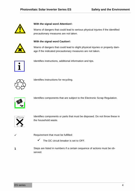
With the signal word Attention!:
Warns of dangers that could lead to serious physical injuries if the identified
precautionary measures are not taken.
With the signal word Caution!:
Warns of dangers that could lead to slight physical injuries or property dam-
age if the indicated precautionary measures are not taken.
Identifies instructions, additional information and tips.
Identifies instructions for recycling.
Identifies components that are subject to the Electronic Scrap Regulation.
Identifies components or parts that must be disposed. Do not throw these in
the household waste.
Requirement that must be fulfilled:
The DC circuit breaker is set to OFF.
1 Steps are listed in numbers if a certain sequence of actions must be ob-
served.

Photovoltaic Solar Inverter Series ES Safety and the Environment
ES series 5
A step is not numbered if the action only involves one step or if the step is
optional.
" ... " Sample entries are in quotes:
The value "0" causes the following...
Bold text Elements on the programme surface or device display:
The device description appears in File list of devices/parameters.
…>… Functions/paths within a menu:
Start > All programmes > EFFEKTA > XYZ Software.
[ ] Keys that cause an action to start:
Confirm the entry with [OK].
ESC Keys on the device or keypad:
Press ESC.

Photovoltaik Wechselrichter Serie ES Table of Contents
ES series 6
Table of Contents
1. INTRODUCTION ........................................................................................... 8
2. SAFETY ..................................................................................................... 9
2.1 General safety instructions ...................................................................... 9
2.2 Information about housing ..................................................................... 10
2.3 Information about PV module ................................................................ 10
2.4 Information about mains connection ...................................................... 11
3. OVERVIEW OF PRODUCT ........................................................................... 12
3.1 Dimensions ............................................................................................ 12
3.2 Display and connections ........................................................................ 13
4. INSTALLATION .......................................................................................... 14
4.1 Checking the device and scope of delivery ........................................... 14
4.2 Ambient conditions for installation ......................................................... 16
4.3 Installation of the PV solar inverter ........................................................ 18
5. ELECTRICAL INSTALLATION ...................................................................... 20
5.1 Connecting AC power cable .................................................................. 20
5.2 Connecting PV module .......................................................................... 24 5.2.1 Requirements of PV module ..................................................... 24 5.2.2 Attaching cables for PV module ................................................ 24 5.2.3 Overview of cables for the PV module ...................................... 27
6. CONTROL PANEL ...................................................................................... 28
7. COMMISSIONING....................................................................................... 30
7.1 Starting device for the first time ............................................................. 30
7.2 Country settings, operating mode settings and ID settings ................... 31
7.3 Commissioning the PV solar inverter ..................................................... 33
7.4 Checking measurement readings and numbers .................................... 34
7.5 Operating status of the PV solar inverter ............................................... 37
8. COMMUNICATION INTERFACES .................................................................. 39
8.1 Standard communication interface ........................................................ 39 8.1.1 Settings for the RS-232 interface .............................................. 39 8.1.2 Pin assignment for the RS-232 interface .................................. 39
8.2 Solar-LogTM .......................................................................................... 39
8.3 Optional data cards ................................................................................ 40

Photovoltaik Wechselrichter Serie ES Table of Contents
ES series 7
8.3.1 Installing communication card ................................................... 40 8.3.2 RS-485 card .............................................................................. 42 8.3.3 Connecting the RS 485 ............................................................. 43 8.3.4 USB card ................................................................................... 45 8.3.5 Relay contact of card (DCE-B card) .......................................... 46 8.3.6 SNMP card ................................................................................ 47
9. STATUS DIAGNOSIS AND TROUBLESHOOTING ............................................ 48
9.1 Error codes and explanations ................................................................ 48
9.2 Mains error alarm codes and explanations ............................................ 51
10. SERVICE .................................................................................................. 54
11. TECHNICAL DATA ..................................................................................... 55
11.1 Device specifications ............................................................................. 55
11.2 Block diagram of ES2200 / ES3300 ...................................................... 58
11.3 ES4200 / ES5000 Block diagram .......................................................... 59
11.4 Scope of delivery / (optional) accessories ............................................. 60
12. DECLARATION OF CONFORMITY ................................................................ 63
13. WARRANTY AND LIABILITY ........................................................................ 64
13.1 Warranty conditions ............................................................................... 64
13.2 Limitation of liability ................................................................................ 65
Photovoltaic Solar Inverter Series ES Introduction
ES series 8
1. Introduction
Thank you for deciding to purchase a photovoltaic solar inverter from the ES
series.
Many years of experience in the production of power supply devices have gone
into the construction of this device. We hope that this device supports your so-
lar system for many years without a glitch.
The PV solar inverter is a complex electronic system that must deal with many
regional supply conditions. If you have questions about this, or if faulty opera-
tion occurs, please do not hesitate to contact your authorised dealer. He will try
to help you as quickly and easily as possible.
Photovoltaic Solar Inverter Series ES Safety
ES series 9
2. Safety
2.1 General safety instructions
This operating manual contains important instructions that you must follow dur-
ing the installation and operation.
For this reason, please read and heed the operating manual and the safety in-
structions provided in this chapter before you take any additional steps.
Work on the device is to be performed solely by authorised professional staff.
Attention!
Faulty operation and incorrectly performed work can cause serious injuries
and property damage.
The installation of your PV solar inverter in accordance with the respective
requirements may only be handled by authorised professional staff.
Attention! Danger of electric shock
Do not perform any work on the PV solar inverter if this work is not described
in this operating manual.
The PV solar inverter contains capacitors. These require at least 12 minutes
to be discharged to a safe level if the supply of power is interrupted.
Attention! Danger of burns
Some components of this device can reach high temperatures.
Do not touch these components!

Photovoltaic Solar Inverter Series ES Safety
ES series 10
2.2 Information about housing
Attention!: Danger of electric shock
Only open the covers of the connections on the PV solar inverter when the
device has been separated from the supply of electricity and has no voltage.
The covers and the housing may only be opened by authorised professional
staff.
2.3 Information about PV module
Before you connect the PV module, check whether the voltage parameters in
the manufacturer's Technical data correspond to the actual parameters.
When reading the voltage, be sure that the PV module achieves a higher open
circuit voltage at lower temperatures and unchanged solar radiation.
At -20 °C, the open circuit voltage of the PV module may not be above 500 V.
To determine the theoretical open circuit voltage at -20 °C, use the tempera-
ture factors in the data sheet of the PV module.
If the open circuit voltage of the PV module is over 500 V, the PV module
may not be connected since the warranty is forfeited in such cases.
The PV solar inverter contains a monitoring unit for fault currents in accor-
dance with VDE 0126-1-1. This unit measures the ground current of the PV
module and prevents a feeding into the mains in the event of a ground fault.

Photovoltaic Solar Inverter Series ES Safety
ES series 11
2.4 Information about mains connection
The PV solar inverter may only be connected to the mains by appropriately li-
censed specialists.
Please contact your regional energy supplier with regard to special require-
ments.
Permission from the energy provider/supplier must be obtained for the connec-
tion of the PV solar inverter.
Photovoltaic Solar Inverter Series ES Overview of product
ES series 12
3. Overview of product
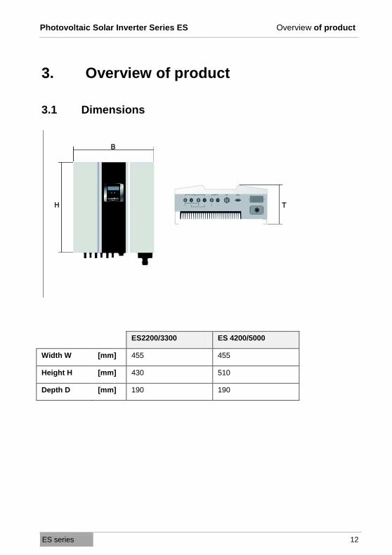
3.1 Dimensions
ES2200/3300 ES 4200/5000
Width W [mm] 455 455
Height H [mm] 430 510
Depth D [mm] 190 190
Photovoltaic Solar Inverter Series ES Overview of product
ES series 13
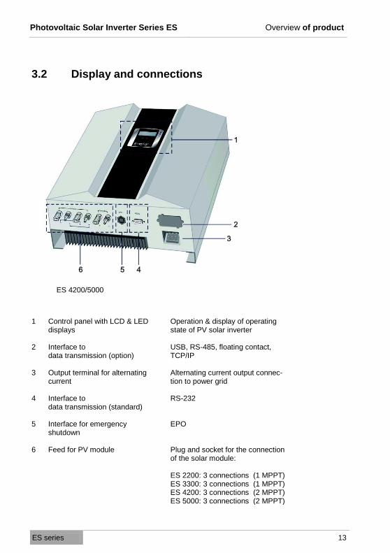
3.2 Display and connections
ES 4200/5000
1 Control panel with LCD & LED displays
Operation & display of operating state of PV solar inverter
2 Interface to data transmission (option)
USB, RS-485, floating contact, TCP/IP
3 Output terminal for alternating current
Alternating current output connec-tion to power grid
4 Interface to data transmission (standard)
RS-232
5 Interface for emergency shutdown
EPO
6 Feed for PV module Plug and socket for the connection of the solar module: ES 2200: 3 connections (1 MPPT) ES 3300: 3 connections (1 MPPT) ES 4200: 3 connections (2 MPPT) ES 5000: 3 connections (2 MPPT)

Photovoltaic Solar Inverter Series ES Installation
ES series 14
4. Installation
Please read the chapter "Safety" on page 9 before connecting the PV solar
inverter.
4.1 Checking the device and scope of delivery
Check the completeness of the package and the device for any damage after
receiving the PV solar inverter. Although the manufacturer ensures a safe
packaging of the product, damage can nonetheless occur during transport. In-
form the transport company and your dealer about damage that has occurred.
The packaging of the PV solar inverter can be recycled.
Save the packaging for future use or dispose of it accordingly.
The standard delivery for a PV solar inverter consists of:
o 1 PV solar inverter
o 1 operating manual
o 1 set of PV connectors
o 1 set of sealing caps for the PV connection
o 1 wall mounting
Photovoltaic Solar Inverter Series ES Installation
ES series 15
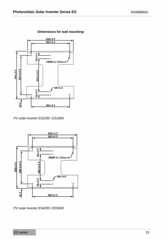
Dimensions for wall mounting:
PV solar inverter ES2200 / ES3300
PV solar inverter ES4200 / ES5000
Photovoltaic Solar Inverter Series ES Installation
ES series 16
4.2 Ambient conditions for installation
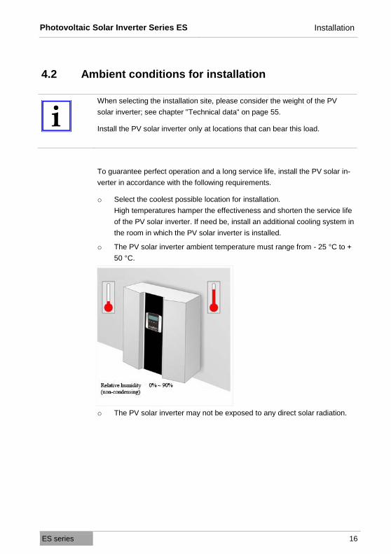
When selecting the installation site, please consider the weight of the PV
solar inverter; see chapter "Technical data“ on page 55.
Install the PV solar inverter only at locations that can bear this load.
To guarantee perfect operation and a long service life, install the PV solar in-
verter in accordance with the following requirements.
o Select the coolest possible location for installation.
High temperatures hamper the effectiveness and shorten the service life
of the PV solar inverter. If need be, install an additional cooling system in
the room in which the PV solar inverter is installed.
o The PV solar inverter ambient temperature must range from - 25 °C to +
50 °C.
o The PV solar inverter may not be exposed to any direct solar radiation.
Photovoltaic Solar Inverter Series ES Installation
ES series 17
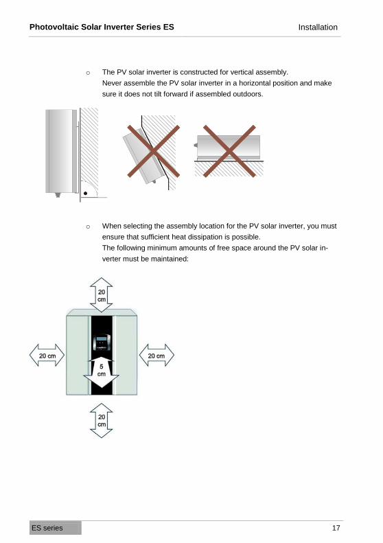
o The PV solar inverter is constructed for vertical assembly.
Never assemble the PV solar inverter in a horizontal position and make
sure it does not tilt forward if assembled outdoors.
o When selecting the assembly location for the PV solar inverter, you must
ensure that sufficient heat dissipation is possible.
The following minimum amounts of free space around the PV solar in-
verter must be maintained:

Photovoltaic Solar Inverter Series ES Installation
ES series 18
4.3 Installation of the PV solar inverter
Use the supplied wall mounting for the installation of the PV solar inverter.
For vertical installation, heed the weight of the PV solar inverter when select-
ing the material to which it will be attached; see chapter "Technical data” on
page 55.
You can use the wall mounting to mark the holes for drilling. If you do not
want to use the wall mounting as a template for the drill holes, please note the
dimensions of the wall mounting in chapter "Checking the device and scope
of delivery“ on page 14.
To mount the PV solar inverter, proceed as follows:
1 Mark the positions for the drill holes on the wall.
2 Drill the holes in accordance with the screws you have selected.
3 Screw on the wall mounting.

Photovoltaic Solar Inverter Series ES Installation
ES series 19
4 Hang the PV solar inverter on the wall mounting.
Use the upper carrier plate so that the PV solar inverter cannot slip.
5 Check whether the PV solar inverter is safely attached to the mounting.

Photovoltaic Solar Inverter Series ES Electrical installation
ES series 20
5. Electrical installation
Attention! Danger of electric shock
The system contains components with high voltage and high current. For this
reason, improper handling can lead to accidents with deadly consequences or
property damage.
Wiring of PV solar inverter Example (ES4200/5000
5.1 Connecting AC power cable
Connection conditions
o Heed the connection conditions of your mains operator.
o Pay attention to the locally required country settings on the PV solar
inverter; see chapter "Country settings, operating mode settings and ID
settings on page 31.

Photovoltaic Solar Inverter Series ES Electrical installation
ES series 21
Ground fault circuit breaker
The PV solar inverter is equipped with an integrated fault current monitoring
unit.
If an external RCD or FI circuit breaker is required, please use a type B circuit
breaker which triggers above a 100 mA fault current.
Cable line layout
o The mains line resistance should not exceed 0.1 Ω.
o Your electricity supplier must calculate the maximum line lengths after
taking the cross section of the line into consideration.
The following cable sizes are recommended for the AC power cables:
Model Line cross section
ES2200 / ES3300 4 mm2
ES4200 / ES5000 6 mm2
Overview of the cable lines
Photovoltaic Solar Inverter Series ES Electrical installation
ES series 22
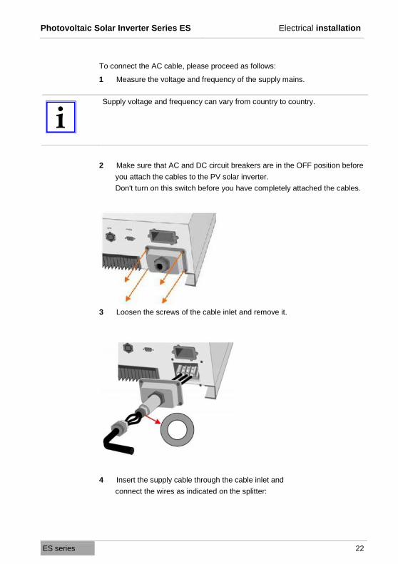
To connect the AC cable, please proceed as follows:
1 Measure the voltage and frequency of the supply mains.
Supply voltage and frequency can vary from country to country.
2 Make sure that AC and DC circuit breakers are in the OFF position before
you attach the cables to the PV solar inverter.
Don't turn on this switch before you have completely attached the cables.
3 Loosen the screws of the cable inlet and remove it.
4 Insert the supply cable through the cable inlet and
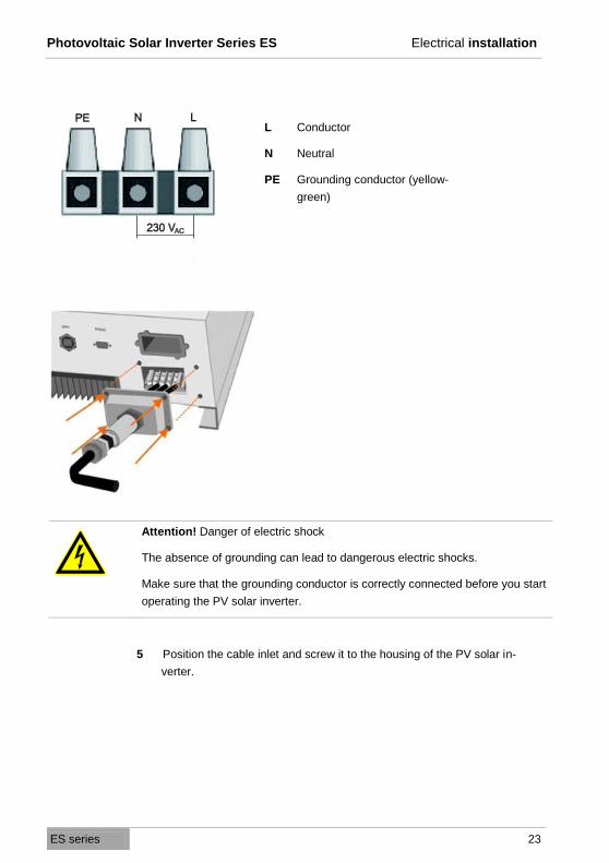
connect the wires as indicated on the splitter:
Photovoltaic Solar Inverter Series ES Electrical installation
ES series 23
L
N
PE
Conductor
Neutral
Grounding conductor (yellow-
green)
Attention! Danger of electric shock
The absence of grounding can lead to dangerous electric shocks.
Make sure that the grounding conductor is correctly connected before you start
operating the PV solar inverter.
5 Position the cable inlet and screw it to the housing of the PV solar in-
verter.
Photovoltaic Solar Inverter Series ES Electrical installation
ES series 24
5.2 Connecting PV module
5.2.1 Requirements of PV module
The PV solar inverters ES4200 and ES5000 use 2 MPP trackers. Tracker A
can be connected to up to 2 strings and Tracker B can be conected to one
string.
The PV solar inversters ES2200 and ES3300 have only one Tracker, that can
be connected to up to 3 strings. The maximum DV input voltage of 500V and
the maximum input current must not be exceeded.
The connection cable of the PV module must be designed for these connec-
tions.
A set of connectors for connecting the line ends of a string is included in the
scope of delivery. The type descriptions for other PV connectors are:
o Connection plug: PV-KST4/6II-UR
o Coupling connector: PV-KBT4/6II-UR
You will find more information online at www.multi-contact.com.
5.2.2 Attaching cables for PV module
The PV solar inverter is equipped with PV quick connecting terminals. These
permit the connection of up to two strings for ES2200 and ES3300 and up to
three strings for ES4200 and ES5000.
The connection of additional strings is possible. These must be externally
connected.

Photovoltaic Solar Inverter Series ES Electrical installation
ES series 25
Attention! Danger of electric shock
Make sure that the DC circuit breaker is located in the position OFF before
you connect the PV module.
Attention! Danger of property damage
In determining the required panels in the PV string, please consider the follow-
ing points:
o To avoid damage to the PV solar inverter, make sure that the output on
the PV module is never above 500 VDC.
Make sure that the maximum open circuit voltage UOC of each PV string
is less than 500 VDC. Voltage of over 500 VDC may damage the PV solar
inverter.
o Make sure that the short circuit current of the module is not greater than
the measurement on the PV solar inverter.
o To achieve the maximum energy output from your PV module, make sure
that the voltage does not fall below 150 VDC at maximum Mpp perform-
ance or exceed 450 VDC.
o The following applies for the PV solar inverters ES4200 and ES500: To
achieve the greatest effectiveness, both trackers should be laid out
roughly symmetrically for the purpose of performance.
o Within one tracker, only modules of the same type with the same power
can be used.
Important: For ES4200 and ES5000 the best efficiency will be obtained
when both trackers have symmetric power confguration.
PV quick connections

Photovoltaic Solar Inverter Series ES Electrical installation
ES series 26
To connect the PV module to the PV solar inverter, proceed as follows:
1 Test whether the generator terminals have the correct polarity and do not
exceed the maximum voltage for each string.
2 Connect the positive (+) wire of the PV string 1 to the positive quick con-
nection terminal on the PV solar inverter.
3 Connect the negative (-) wire of the PV string 1 to the negative quick con-
nection terminal on the PV solar inverter.
o Repeat steps 2 and 3 for other PV strings.
4 Check whether all wires and contacts have been connected correctly.
5 Cover the unused sockets of the DC input with the supplied protective
caps.
Photovoltaic Solar Inverter Series ES Electrical installation
ES series 27
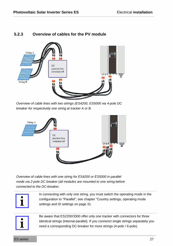
5.2.3 Overview of cables for the PV module
Overview of cable lines with two strings (ES4200, ES5000 via 4-pole DC
breaker for respectively one string at tracker A or B.
Overview of cable lines with one string for ES4200 or ES5000 in parallel
mode via 2-pole DC breaker (all modules are mounted to one string before
connected to the DC-breaker.
In connecting with only one string, you must switch the operating mode in the
configuration to "Parallel"; see chapter "Country settings, operating mode
settings and ID settings on page 31.
Be aware that ES2200/3300 offer only one tracker with connectors for three
identical strings (internal parallel). If you connenct single strings separately you
need a corresponding DC-breaker for more strings (4-pole / 6-pole).
Photovoltaic Solar Inverter Series ES Control panel
ES series 28
6. Control panel
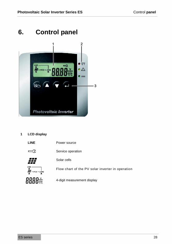
1 LCD display
LINE Power source
Service operation
Solar cells
Flow chart of the PV solar inverter in operation
4-digit measurement display

Photovoltaic Solar Inverter Series ES Control panel
ES series 29
2 LED display
Red LED lights up constantly - indicates a ground fault or
an isolation fault at the DC input.
Yellow LED lights up constantly - indicates that the supply
(voltage, frequency, etc.) does not correspond to the en-
tered standard of the PV solar inverter.
o Green LED lights up constantly - indicates that the
performance of the solar cells is greater than 5 % of
the nominal performance of the solar inverter.
o Green LED blinks - indicates that the performance of
the solar cells is less than 5 % of the nominal per-
formance of the PV solar inverter.
3 Operating keys
Confirm a change to the settings of the PV solar inverter.
Continue to next page or change the settings of the PV
solar inverter.
Return to the previous page or change the settings of the
PV solar inverter.
Special function Log in / Log out.
Photovoltaic Solar Inverter Series ES Commissioning
ES series 30
7. Commissioning
Attention! Danger of electric shock
Check the following points before you start up the PV solar inverter:
o The housing is safely screwed in place.
o The DC cables (PV strings) are correctly connected and that unused DC
connection terminals on the bottom of the housing are covered with safety
caps.
o The AC cable is connected correctly.
o The AC switch is OFF.
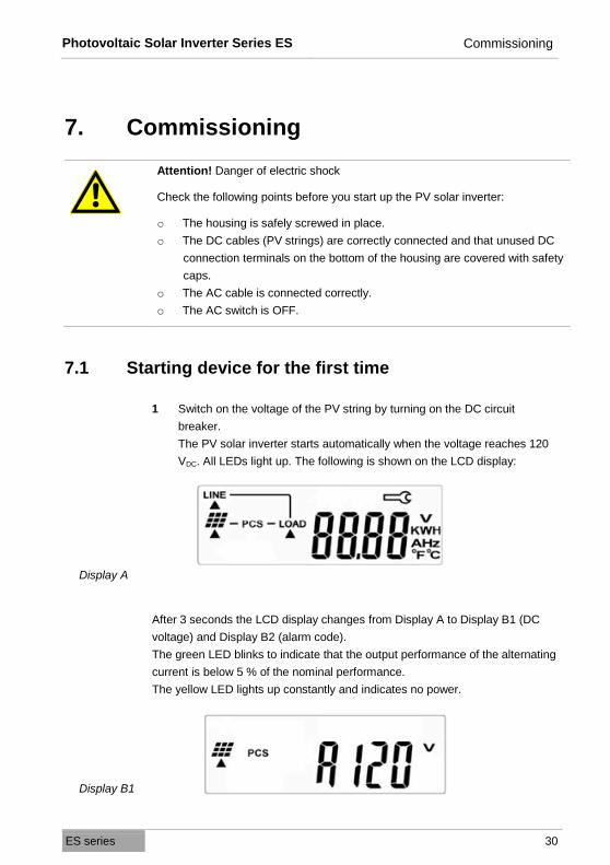
7.1 Starting device for the first time
1 Switch on the voltage of the PV string by turning on the DC circuit
breaker.
The PV solar inverter starts automatically when the voltage reaches 120
VDC. All LEDs light up. The following is shown on the LCD display:
Display A
After 3 seconds the LCD display changes from Display A to Display B1 (DC
voltage) and Display B2 (alarm code).
The green LED blinks to indicate that the output performance of the alternating
current is below 5 % of the nominal performance.
The yellow LED lights up constantly and indicates no power.
Display B1

Photovoltaic Solar Inverter Series ES Commissioning
ES series 31
Display B2
7.2 Country settings, operating mode settings and ID
settings
IMPORTANT!
SETTINGS ALREADY CONFIGURED IN FACTORY.
CHANGES ONLY TO BE MADE USING LAPTOP AND SETTING TOOL.
Caution! Danger of property damage
False country settings can compromise your mains electricity, cause the solar
inverter to malfunction and lead to the termination of your authorisation to
operate the device.
IMPORTANT!
Before changing the settings assure that the AC switch is OFF.
Photovoltaic Solar Inverter Series ES Commissioning
ES series 32
This page is intentionally left blank.

Photovoltaic Solar Inverter Series ES Commissioning
ES series 33
7.3 Commissioning the PV solar inverter
1 Check whether the DC circuit breaker is switched on and set it to ON if
need be.
2 Set the AC circuit breaker to ON.
3 Wait 30 seconds (legally required waiting period).
The LCD display changes between the Displays C1 (DC voltage) and Dis-
play C2 (alarm code). The yellow LED lights up and the green LED blinks.
Display C1
Display C2
After 30 seconds, the yellow LED goes off and the green LED blinks
again. The LCD display shows Display D.
Display D
After 5 seconds, the LCD display shows Display E. The green LED lights
up constantly.
Display E

Photovoltaic Solar Inverter Series ES Commissioning
ES series 34
If the PV solar inverter is defective (short circuit), an error code or the error
status will appear on the display.
Display F
Information!
A list with the explanations of possible error codes can be found under "Error
codes and explanations“ on page 48.
If the PV solar inverter was started completely and successfully, the LCD
display shows Display E.
7.4 Checking measurement readings and numbers
Via the LCD display, you can check the measurement readings and numbers
set by the PV solar inverter.
o Use the key and the key to switch the displays.
The measurement readings and numbers appear in the following order as
you scroll down:
Display G: Voltage of String A
Display H: Voltage of String B
Display I: Current of String A
Photovoltaic Solar Inverter Series ES Commissioning
ES series 35
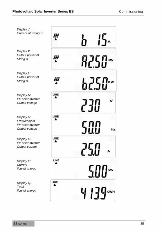
Display J: Current of String B
Display K: Output power of String A
Display L: Output power of String B
Display M: PV solar inverter Output voltage
Display N: Frequency of PV solar inverter Output voltage
Display O: PV solar inverter Output current
Display P: Current flow of energy
Display Q: Total flow of energy

Photovoltaic Solar Inverter Series ES Commissioning
ES series 36
Display R: PV solar inverter Internal temperature
°F
Display S: PV solar inverter Internal temperature
°C
Display T: Temperature of cooling element °F
Display U: Temperature of cooling element °C
Photovoltaic Solar Inverter Series ES Commissioning
ES series 37
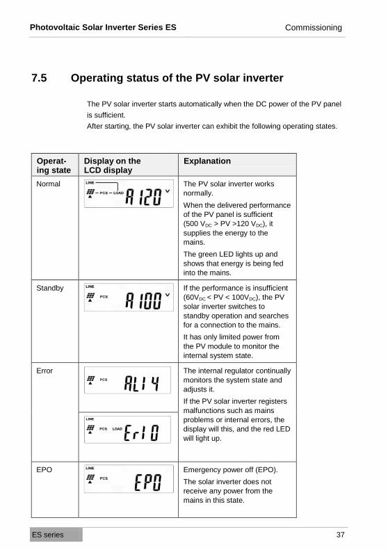
7.5 Operating status of the PV solar inverter
The PV solar inverter starts automatically when the DC power of the PV panel
is sufficient.
After starting, the PV solar inverter can exhibit the following operating states.
Operat-ing state
Display on the LCD display
Explanation
Normal The PV solar inverter works
normally.
When the delivered performance
of the PV panel is sufficient
(500 VDC > PV >120 VDC), it
supplies the energy to the
mains.
The green LED lights up and
shows that energy is being fed
into the mains.
Standby If the performance is insufficient
(60VDC < PV < 100VDC), the PV
solar inverter switches to
standby operation and searches
for a connection to the mains.
It has only limited power from
the PV module to monitor the
internal system state.
Error The internal regulator continually
monitors the system state and
adjusts it.
If the PV solar inverter registers
malfunctions such as mains
problems or internal errors, the
display will this, and the red LED
will light up.
EPO Emergency power off (EPO).
The solar inverter does not
receive any power from the
mains in this state.
Photovoltaic Solar Inverter Series ES Commissioning
ES series 38
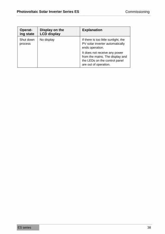
Operat-ing state
Display on the LCD display
Explanation
Shut down
process
No display If there is too little sunlight, the
PV solar inverter automatically
ends operation.
It does not receive any power
from the mains. The display and
the LEDs on the control panel
are out of operation.
Photovoltaic Solar Inverter Series ES Communication interfaces
ES series 39
8. Communication interfaces
You can connect external devices to the PV solar inverter and call up data. The
various communication interfaces are designed for this.
8.1 Standard communication interface
The standard communication interface for the PV solar inverter consists of a
RS-232 serial interface (otherwise described as EIA-232).
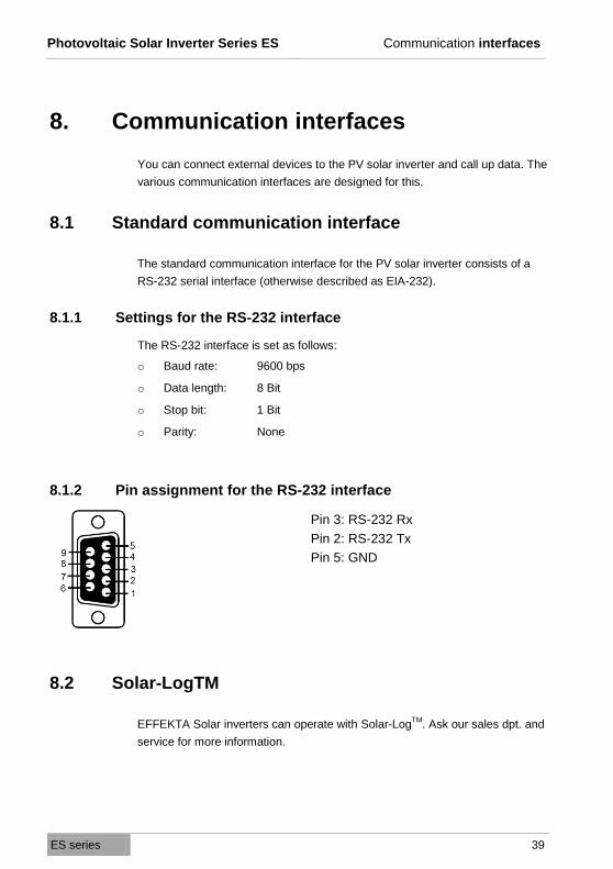
8.1.1 Settings for the RS-232 interface
The RS-232 interface is set as follows:
o Baud rate: 9600 bps
o Data length: 8 Bit
o Stop bit: 1 Bit
o Parity: None
8.1.2 Pin assignment for the RS-232 interface
Pin 3: RS-232 Rx
Pin 2: RS-232 Tx
Pin 5: GND
8.2 Solar-LogTM
EFFEKTA Solar inverters can operate with Solar-LogTM
. Ask our sales dpt. and
service for more information.

Photovoltaic Solar Inverter Series ES Communication interfaces
ES series 40
8.3 Optional data cards
If you need other interfaces than the standard communication interface, you
can install an optional communication card.
ATTENTION!
The data cards can only be mounted, while the inverter is swiched off! Mount-
ing the data cards during operating mode can destroy the inverter.
8.3.1 Installing communication card
1 Loosen the screws and open the cover of the housing.
2 Insert the data cable through the cable inlet of the cover.

Photovoltaic Solar Inverter Series ES Communication interfaces
ES series 41
3 Connect the data cable to the communication card.
4 Insert the communication card in the receiver.
5 Place the cover back on top and tighten the four screws evenly.
Photovoltaic Solar Inverter Series ES Communication interfaces
ES series 42
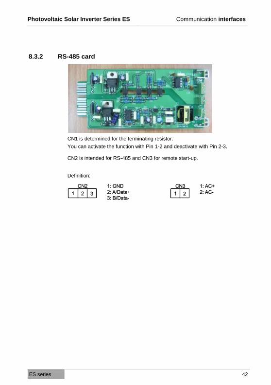
8.3.2 RS-485 card
CN1 is determined for the terminating resistor.
You can activate the function with Pin 1-2 and deactivate with Pin 2-3.
CN2 is intended for RS-485 and CN3 for remote start-up.
Definition:
Photovoltaic Solar Inverter Series ES Communication interfaces
ES series 43
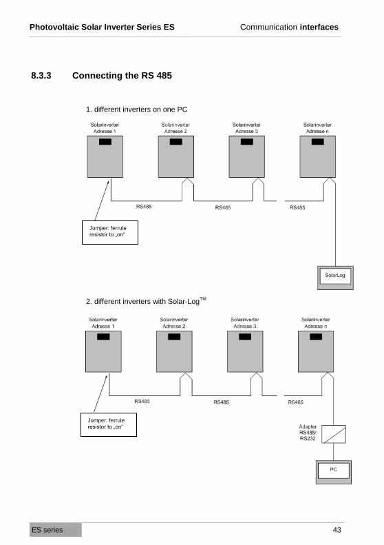
8.3.3 Connecting the RS 485
1. different inverters on one PC
2. different inverters with Solar-LogTM
Jumper: ferrule
resistor to „on“
Jumper: ferrule
resistor to „on“
Photovoltaic Solar Inverter Series ES Communication interfaces
ES series 44
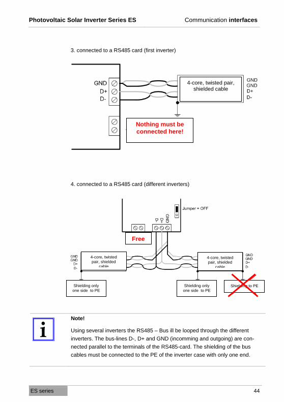
3. connected to a RS485 card (first inverter)
4. connected to a RS485 card (different inverters)
Note!
Using several inverters the RS485 – Bus ill be looped through the different
inverters. The bus-lines D-, D+ and GND (incomming and outgoing) are con-
nected parallel to the terminals of the RS485-card. The shielding of the bus
cables must be connected to the PE of the inverter case with only one end.
4-core, twisted pair, shielded cable
Nothing must be
connected here!
Shielding only
one side to PE Shielding to PE Shielding only
one side to PE
4-core, twisted pair, shielded
cable
4-core, twisted pair, shielded
cable
Free

Photovoltaic Solar Inverter Series ES Communication interfaces
ES series 45
8.3.4 USB card
Definition:
o Compatible USB version 1.0, 1.5Mbit/s
o Compatible HID Version 1.0
Pin assignment for USB card:
1: VCC (+5V)
2: D –
3: D +
4: GND

Photovoltaic Solar Inverter Series ES Communication interfaces
ES series 46
8.3.5 Relay contact of card (DCE-B card)
The pin assignment for the 10 pin terminal:
Pin 1: DC input voltage inside and DC input voltage below
the range
Pin 2: at lest one DC input beyond the min. limit
Pin 3: all DC input voltages below min. limit
Pin 4: Frequency of AC output (network) out of tolerance
Pin 5: island solution switched off
Pin 6: Output current of the inverter above the tolerance
Pin 7: The heat sink temperature of the inverter is too high
Pin 8: Common
Each relay contact can bear a load of max 40 VDC / 25 mA.
You can switch over the output signal from N.C. (normal close)
to N.O. (normal open) by bridging Pin 1 and 2 or Pin 2 and 3
from JP1-5 with the jumpers.
Photovoltaic Solar Inverter Series ES Communication interfaces
ES series 47
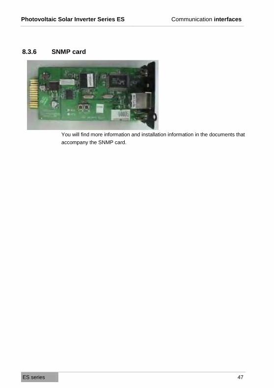
8.3.6 SNMP card
You will find more information and installation information in the documents that
accompany the SNMP card.

Photovoltaic Solar Inverter Series ES Status diagnosis and troubleshooting
ES series 48
9. Status diagnosis and troubleshooting
The PV solar inverter is equipped with a self-diagnosis system that identifies a
large number of possible operating conditions independently and shows them
on the LCD display. This makes it possible to quickly eliminate technical prob-
lems.
Furthermore, a distinction is possible between
o service codes concerning installation and
o service codes that relate internally to the PV solar inverter.
Whenever the self-diagnosis system identifies a particular problem, the corre-
sponding service code is showed on the LCD display.
Information!
The following work may only be performed by trained technical staff.
9.1 Error codes and explanations
LCD display
Description Explanation Troubleshooting
Er00 DC _BUS
pre-charge defect
The device is in the soft
start mode, but after 2
seconds you do not see
any stable charging volt-
age on the DC bus.
1 Disconnect all PV(+) -
or PV(-) connections.
2 Wait a few seconds.
3 After the LCD display
goes out, reinsert all
the connections and
check it again.
4 If the error still occurs,
please contact your
dealer.
Er03 Inverter voltage
abnormal
The output voltage is not
correct.
Er07 DC_BUS
over-voltage
The internal voltage of the
DC bus is outside the
tolerance. Er08 DC_BUS
under-voltage
Er19 DC_BUS
discharge defect
The capacitors of the DC
bus cannot be discharged
correctly.
1. Disconnect all PV(+) -
or PV(-) connections.
2. Wait a few seconds.
3. After the LCD display Er22 Output relay
defect
Malfunction on the output
relay of the solar inverter.

Photovoltaic Solar Inverter Series ES Status diagnosis and troubleshooting
ES series 49
LCD display
Description Explanation Troubleshooting
Er24 Output current
sense defect
Error in the output current
reading.
switches off, reinsert
all the connections
and check it again.
4. If the error still occurs,
please contact your
dealer.
Er25 BOOSTER_A
over-current
The current in the DC
mains is higher than ex-
pected. Er26 BOOSTER_B
over-current
Er29 PV inverter
output DC current
over spec.
DC current at output of
solar inverter is too high.
Er06 EPO The PV solar inverter is in
the emergency power off
mode.
1. Detach the connec-
tion at the EPO con-
nection.
2. If the error still occurs,
please contact your
dealer.
Er09 PV inverter
over-current
Over-current on the AC
side. The current in the AC
mains is higher than ex-
pected.
1. Turn off the AC cur-
rent switch; check the
peripheral AC current
system configurations
and the mains condi-
tions.
2. If the error still occurs,
please contact your
dealer.
Er11 PV inverter
over-load
Over-load on the AC side.
The mains load in the AC
mains is higher than ex-
pected.
Er13 PV inverter
short-circuit
Short circuit on the
AC side.
Er14 PV inverter
PLL defect
The PV solar inverter is
not in phase with the
mains electricity.
Er10 PV inverter
over temperature
The internal temperature
is too high.
1. Try to reduce the
surrounding tempera-
ture.
2. Install the solar in-
verter in a cooler
place.
3. If the error still occurs,
please contact your
dealer.
Er18 Heatsink
over temperature
The temperature on the
cooling element is too
high.
Photovoltaic Solar Inverter Series ES Status diagnosis and troubleshooting
ES series 50
LCD display
Description Explanation Troubleshooting
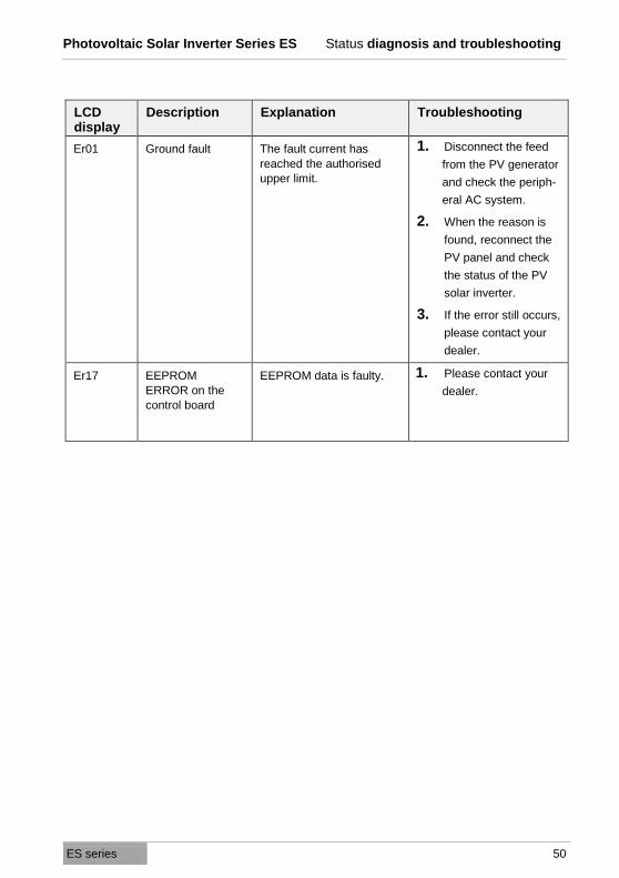
Er01 Ground fault The fault current has
reached the authorised
upper limit.
1. Disconnect the feed
from the PV generator
and check the periph-
eral AC system.
2. When the reason is
found, reconnect the
PV panel and check
the status of the PV
solar inverter.
3. If the error still occurs,
please contact your
dealer.
Er17 EEPROM
ERROR on the
control board
EEPROM data is faulty. 1. Please contact your
dealer.

Photovoltaic Solar Inverter Series ES Status diagnosis and troubleshooting
ES series 51
9.2 Mains error alarm codes and explanations
LCD display
Description Explanation Troubleshooting
AL00 Utility voltage
over-voltage
The mains voltage is
higher or lower
than the authorised
amount.
1. Wait 5 minutes. When
the mains supply be-
comes normal again,
the solar inverter
starts up automati-
cally.
2. Check the mains con-
nection (cable and
terminals).
3. Make sure the mains
voltage and frequency
meet the requirements.
4. If the error still occurs,
please contact your
dealer.
AL01 Utility voltage
under-voltage
AL02 Utility voltage over
frequency
The mains frequency is
higher or lower than the
authorised amount. AL03 Utility voltage
under frequency
AL04 BOOSTER_A
Input
over-voltage
Under or over-voltage of
the DC input.
1. Disconnect all PV(+) -
or PV(-) connections.
2. Check whether the PV
voltage is higher or at
500 VDC.
3. If the voltage is below
500 VDC and the prob-
lem persists, please
contact your dealer.
AL05 BOOSTER_A
Input
under-voltage
AL06 BOOSTER_B
Input
over-voltage
AL07 BOOSTER_B
Input
under-voltage
Photovoltaic Solar Inverter Series ES Status diagnosis and troubleshooting
ES series 52
LCD display
Description Explanation Troubleshooting
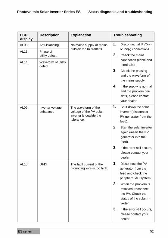
AL08 Anti-islanding No mains supply or mains
outside the tolerances.
1. Disconnect all PV(+) -
or PV(-) connections.
2. Check the mains
connection (cable and
terminals).
3. Check the phasing
and the waveform of
the mains supply.
4. If the supply is normal
and the problem per-
sists, please contact
your dealer.
AL13 Phase of
utility defect
AL14 Waveform of utility
defect
AL09 Inverter voltage
unbalance
The waveform of the
voltage of the PV solar
inverter is outside the
tolerance.
1. Shut down the solar
inverter (disconnect
PV generator from the
feed).
2. Start the solar inverter
again (insert the PV
generator into the
feed).
3. If the error still occurs,
please contact your
dealer.
AL10 GFDI The fault current of the
grounding wire is too high.
1. Disconnect the PV
generator from the
feed and check the
peripheral AC system.
2. When the problem is
resolved, reconnect
the PV. Check the
status of the solar in-
verter.
3. If the error still occurs,
please contact your
dealer.
Photovoltaic Solar Inverter Series ES Status diagnosis and troubleshooting
ES series 53
LCD display
Description Explanation Troubleshooting
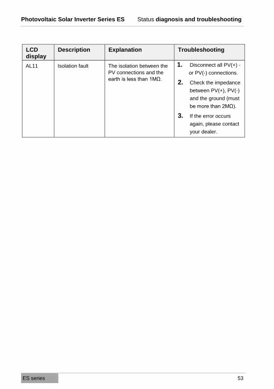
AL11 Isolation fault The isolation between the
PV connections and the
earth is less than 1MΩ.
1. Disconnect all PV(+) -
or PV(-) connections.
2. Check the impedance
between PV(+), PV(-)
and the ground (must
be more than 2MΩ).
3. If the error occurs
again, please contact
your dealer.

Photovoltaic Solar Inverter Series ES Service
ES series 54
10. Service
There are no parts on the PV solar inverter that have to be maintained by the
customer.
Clean the device at regular intervals with a dry, soft towel to avoid an accumu-
lation of dust.
In particular, clean the cooling fins on the back of the device.
Service hotline and contact addresses
If unexpected problems occur with the PV solar inverter or you need safety in-
formation, please contact our service hotline:
o Phone number: +49 (0) 741 17451-0
o Fax number: +49 (0) 741 17451-29
If you cannot reach us by phone or fax, we have set up an e-mail contact for
you:
You will also find additional contact addresses online at:
http://www.effekta.com/html/kontakt.html.
You will find the entire spectrum of our services at:
http://www.effekta.com/html/service/html.
A form for the exchange of inverters can be found at
http://www.effekta.com/pdf/Austausch_Solarwechselrichter_EN.zip
Photovoltaic Solar Inverter Series ES Technical data
ES series 55
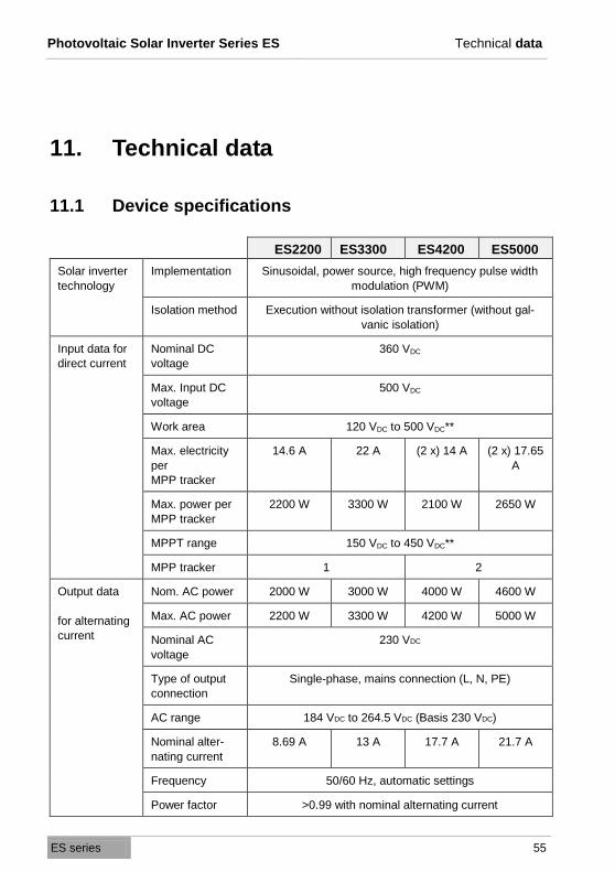
11. Technical data
11.1 Device specifications
ES2200 ES3300 ES4200 ES5000
Solar inverter
technology
Implementation Sinusoidal, power source, high frequency pulse width
modulation (PWM)
Isolation method Execution without isolation transformer (without gal-
vanic isolation)
Input data for
direct current
Nominal DC
voltage
360 VDC
Max. Input DC
voltage
500 VDC
Work area 120 VDC to 500 VDC**
Max. electricity
per
MPP tracker
14.6 A 22 A (2 x) 14 A (2 x) 17.65
A
Max. power per
MPP tracker
2200 W 3300 W 2100 W 2650 W
MPPT range 150 VDC to 450 VDC**
MPP tracker 1 2
Output data
for alternating
current
Nom. AC power 2000 W 3000 W 4000 W 4600 W
Max. AC power 2200 W 3300 W 4200 W 5000 W
Nominal AC
voltage
230 VDC
Type of output
connection
Single-phase, mains connection (L, N, PE)
AC range 184 VDC to 264.5 VDC (Basis 230 VDC)
Nominal alter-
nating current
8.69 A 13 A 17.7 A 21.7 A
Frequency 50/60 Hz, automatic settings
Power factor >0.99 with nominal alternating current

Photovoltaic Solar Inverter Series ES Technical data
ES series 56
ES2200 ES3300 ES4200 ES5000
Distortion factor
of current (sinus
deviation)
Percentage of total harmonious vibration: Below 5%
percent of harmonious individual vibration: Below 3%
Efficiency data Max. implemen-
tation perform-
ance
> 96%
Euro power > 94%
CEC power > 94%
Standby con-
sumption
< 7 W
Night-time con-
sumption
< 0.15 W
Environment Operating tem-
perature
-25 °C to +50 °C (-13 °F to 122 °F)
Humidity 0 to 90% (without condensation)
Technology Dimensions (H x
W x D in mm)
430 x 455 x 170 510 x 455 x 170
Weight (net) 27 kg 29 kg
Weight (gross) 30.5 kg 32.5 kg
Protection class IP65 (outdoor area)
Cooling Convection
Alternating
current connec-
tion
Screw connection
DC connection MC4 plug
Communica-
tion
Standard RS-232
Optional USB, RS-485, relay contact, SNMP
Control panel LCD display Input DC voltage / input direct current / input DC power
/ output AC voltage / output alternating current / output
frequency / output AC power /
Energy output / internal temperature / cooling element
temperature / status message / error message
LED display Red: Grounding fault or DC
input isolation fault

Photovoltaic Solar Inverter Series ES Technical data
ES series 57
ES2200 ES3300 ES4200 ES5000
Yellow: Supply conditions do
not correspond to the
input standard of the
PV solar inverter
Green: Performance of solar
cells is above or below
5 % of the nominal
performance of the
PV solar inverter
Operating keys Navigation keys / function key / enter key
Safety Mains Over-/ under-voltage, over-/ under-frequency, ground-
ing fault, DC isolation error, isolated operation
Short circuit DC input: Reverse pole protection / electronic switching
AC output: Output relay / electronic switching
EPO (emer-
gency power off)
The PV solar inverter switches off immediately
Over-
temperature
≤ 50 °C (122 °F) at full capacity
≥ 50 °C(122 °F) at reduced capacity
Certification Safety Europe VDE0126-1-1, EN50178, IEC62103
EMI/EMC EN 61000-6-1, EN 61000-6-2,
EN 61000-6-3, EN 61000-6-4
** The nominal area should be between 150 VDC and 500 VDC to achieve nominal power.
Photovoltaic Solar Inverter Series ES Technical data
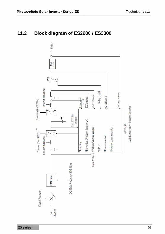
ES series 58
11.2 Block diagram of ES2200 / ES3300
Photovoltaic Solar Inverter Series ES Technical data
ES series 59
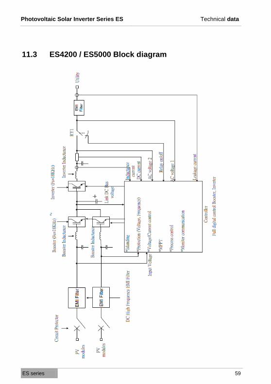
11.3 ES4200 / ES5000 Block diagram
Photovoltaic Solar Inverter Series ES Technical data
ES series 60
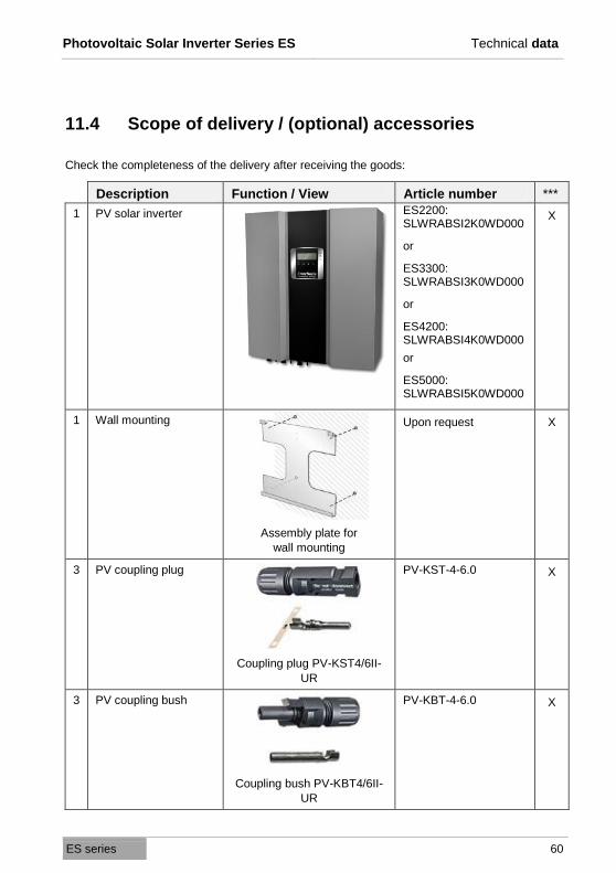
11.4 Scope of delivery / (optional) accessories
Check the completeness of the delivery after receiving the goods:
Description Function / View Article number ***
1 PV solar inverter ES2200: SLWRABSI2K0WD000
or
ES3300: SLWRABSI3K0WD000
or
ES4200: SLWRABSI4K0WD000
or
ES5000: SLWRABSI5K0WD000
X
1 Wall mounting
Assembly plate for
wall mounting
Upon request X
3 PV coupling plug
Coupling plug PV-KST4/6II-
UR
PV-KST-4-6.0 X
3 PV coupling bush
Coupling bush PV-KBT4/6II-
UR
PV-KBT-4-6.0 X
Photovoltaic Solar Inverter Series ES Technical data
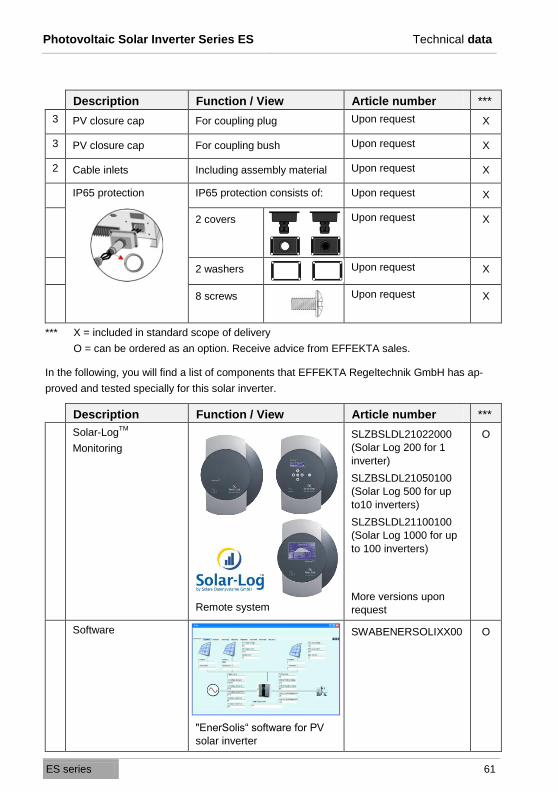
ES series 61
Description Function / View Article number ***
3 PV closure cap For coupling plug Upon request X
3 PV closure cap For coupling bush Upon request X
2 Cable inlets Including assembly material Upon request X
IP65 protection
IP65 protection consists of: Upon request X
2 covers Upon request X
2 washers Upon request X
8 screws Upon request X
*** X = included in standard scope of delivery
O = can be ordered as an option. Receive advice from EFFEKTA sales.
In the following, you will find a list of components that EFFEKTA Regeltechnik GmbH has ap-
proved and tested specially for this solar inverter.
Description Function / View Article number ***
Solar-LogTM
Monitoring
Remote system
SLZBSLDL21022000
(Solar Log 200 for 1
inverter)
SLZBSLDL21050100
(Solar Log 500 for up
to10 inverters)
SLZBSLDL21100100
(Solar Log 1000 for up
to 100 inverters)
More versions upon
request
O
Software
"EnerSolis“ software for PV
solar inverter
SWABENERSOLIXX00 O
Photovoltaic Solar Inverter Series ES Technical data
ES series 62
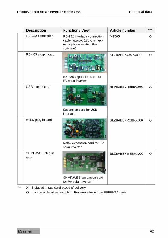
Description Function / View Article number ***
RS-232 connection RS-232 interface connection
cable, approx. 170 cm (nec-
essary for operating the
software)
M2505 O
RS-485 plug-in card
RS-485 expansion card for
PV solar inverter
SLZBABEK485PX000 O
USB plug-in card
Expansion card for USB -
interface
SLZBABEKUSBPX000 O
Relay plug-in card
Relay expansion card for PV
solar inverter
SLZBABEKRCBPX000 O
SNMP/WEB plug-in
card
SNMP/WEB expansion card
for PV solar inverter
SLZBABEKWEBPX000 O
*** X = included in standard scope of delivery
O = can be ordered as an option. Receive advice from EFFEKTA sales.
Photovoltaic Solar Inverter Series ES Declaration of conformity
ES series 63
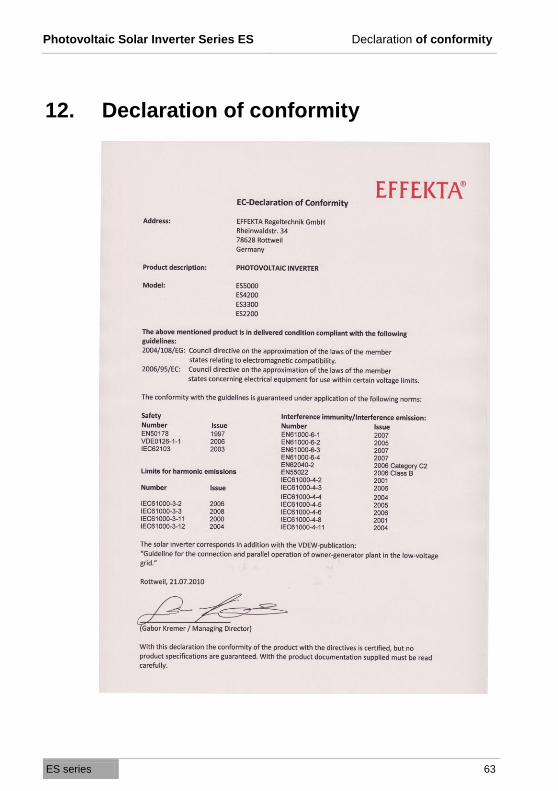
12. Declaration of conformity
Photovoltaic Solar Inverter Series ES Warranty and liability
ES series 64
13. Warranty and liability
13.1 Warranty conditions
The delivery receipt is considered as record of the initial purchase and should
be stored in a safe place. It will be needed to make use of the warranty. If the
product is passed on to another user, he has the right to the rest of the war-
ranty period. The purchase receipt as well as the declaration should also be
given to the new owner if the device is passed on.
We guarantee that this device is in a functional condition and technically con-
forms to the description in the appended documentation.
The warranty period for this device is 5 years from the date of purchase.
The warranty ceases to apply in the following cases:
o In the event of defects from freight damage, accident, natural catastro-
phies, misuse, vandalism, improper use, defective maintenance or incor-
rect repair by third parties.
o In the event of changes, unauthorised intervention, incorrect operation,
use of another device or accessories, false installation or other modifica-
tions not approved by the manufacturer.
o In the event of failure to follow the instructions and safety information in
this documentation.
o In the event of incompatibility of the product due to possible technical in-
novations or regulations that occur after the purchase.
o In the event of incompatibility or malfunctioning that was caused by prod-
uct components that we did not install.
o In the event of developments that are related to the normal aging process
of the product (wear parts).
o In the event of defects that were caused by external fixtures.
o In the event of a violation of the warranty seal.
The warranty period for parts that were replaced and/or repaired on account of
the warranty expires together with the original warranty for the product.

Photovoltaic Solar Inverter Series ES Warranty and liability
ES series 65
Devices that are sent in without accessories are replaced without accessories.
The return of the device is only accepted if this is done in the original packag-
ing.
Incurred transport costs are generally not included in the warranty.
13.2 Limitation of liability
Claims to damage compensation are excluded unless they involve intent or
crude negligence by EFFEKTA Regeltechnik GmbH or its employees. This
does not affect liability according to the Product Liability Act. Under no circum-
stances are we liable for:
o claims that third parties make against you due to losses or damage.
o loss or damage to your drawings or data or the costs of recovering this
data.
o economic subsequent damage (including lost profits or savings) or con-
comitant damage, including where we were informed of the possibility of
such damage.
Under no circumstances is EFFEKTA Regeltechnik GmbH responsible for any
accidental, indirect, specific, subsequent or other damage of any kind (includ-
ing, without any limitation, damage related to a loss of profits, interruption of
business, loss of business information, or any other losses) that result from use
of the device or that are connected with the device whether they are based on
the contract, damage compensation, negligence, strict liability or other claims,
even if EFFEKTA Regeltechnik GmbH was informed about the possibility of
such damage in advance. This exemption also includes any liability that can
result from the claims of third parties against the initial purchaser.
In some countries, the exemption or the limitation of concomitant or subse-
quent damage is not permitted by law so that the aforementioned declaration
does not enter into force.
Photovoltaic Solar Inverter Series ES Warranty and liability
ES series 66
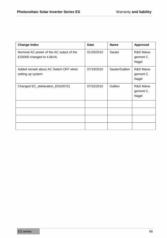
Change Index Date Name Approved
Nominal AC power of the AC output of the
ES5000 changed to 4.6kVA.
01/25/2010 Sauter R&D Mana-
gement C.
Nagel
Added remark about AC Switch OFF when
setting up system
07/19/2010 Sauter/Gallien R&D Mana-
gement C.
Nagel
Changed EC_deklaration_EN100721 07/22/2010 Gallien R&D Mana-
gement C.
Nagel
Photovoltaic Solar Inverter Series ES Warranty and liability
ES series 67

Photovoltaic Solar Inverter Series ES Warranty and liability
ES series 68